


Dayton 3VH34, 3E460, 5VD66, 5VD57, 3E462 User Manual
...Installation, Operation, Maintenance and Parts Manual |
3E132 thru 3E134, 3E460 thru 3E462, |
|
5VD57 thru 5VD66, 3VH34 thru 3VH37 |
||
|
||
|
|
Please read and save these instructions. This heater must be installed and serviced by trained gas installation and service personnel only! Read carefully before attempting to assemble, install, operate or maintain the product described. Protect yourself and others by observing all safety information. Failure to comply with instructions could result in personal injury and/or property damage! Retain these instructions for future reference.
Dayton® High-Intensity Heaters
Description
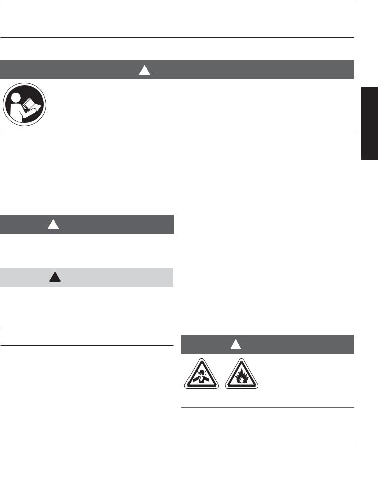
Dayton high-intensity heaters become highly efficient generators of infrared radiation by heating a ceramic refractory material to incandescence. The principal operation is to pass a gas-air mixture
through a perforated ceramic refractory, and ignite it on the refractory surface. This causes the ceramic material to be heated to approximately 1780°F and generate large amounts of infrared radiation that may be directed anywhere heat is desired. Infrared radiation heats people and objects it strikes and not the intervening air. Included is a direct spark ignition system, manifold pressure tap, porous ceramic grids, a polished aluminum reflector and a chain set for hanging the heater. Typical applications are loading docks, warehouses, service garages, factories, aircraft hangars, etc.
! WARNING |
|
! WARNING |
|
|
|
Improper installation, adjustment,
alteration, service or maintenance can cause property damage, injury or death. Read and understand the installation,
operating and maintenance instructions thoroughly before installing or servicing this equipment.
This heater must be installed and serviced by trained gas installation and service personnel only. Failure to comply could result in personal injury, asphyxiation, death, fire and/or property damage.
! WARNING
Not for residential use!
This heater is not approved in any
residential application. This includes (but is not limited to) the home, living
quarters, attached garages, etc. Installation in residential indoor spaces may result in property damage, serious injury or death.
In locations used for the storage of combustible materials, signs must be posted to specify the maximum permissible stacking height to maintain
the required clearances from the heater to the combustibles. Signs must either be posted adjacent to the heater thermostats or in the absence of such thermostats, in a conspicuous location.
For Your Safety
If you smell gas:
•Do not try to light any appliance.
•Do not touch any electrical switch.
•Do not use any phone in your building.
•Immediately call your gas supplier from a neighbor’s phone.
•Follow the gas supplier’s instructions.
•If you cannot reach your gas supplier, call the fire department.
Keep these instructions for future reference.
Form 5S4078 |
Printed in U.S.A. |
® |
|
03460 |
|
|
1006/281/VCPVP |
|
E N G L I S H

|
3E132 thru 3E134, 3E460 thru 3E462, |
Dayton Installation, Operation, Maintenance and Parts Manual |
5VD57 thru 5VD66, 3VH34 thru 3VH37 |
|
|
Dayton® High Intensity Heaters
|
1.0 Safety . . . . . . . . . . . . . . . . . . . . . . . . . . . . . . . . . |
. |
3 |
|
|
Safety Symbols . . . . . . . . . . . . . . . . . . . . . . . . . . . . |
|
3 |
|
|
Applications |
|
3 |
|
E |
. |
|||
Clearance to Combustibles |
|
4 |
||
N |
. |
|||
G |
. . . . . . . . . . . . . . . . . . . . . . . . .Standards, Certifications and Government Regulations |
. |
6 |
|
L |
Heater Dimensions . . . . . . . . . . . . . . . . . . . . . . . . . . . . . . . . . . . . . . . . . . . . . . . . . . . . |
. |
7 |
|
I |
Safety Signs and Labels . . . . . . . . . . . . . . . . . . . . . . . . |
. |
8 |
|
S |
||||
|
|
|
||
H |
|
|
|
|
|
2.0 Installation |
|
9 |
|
|
. |
|||
|
Design . . . . . . . . . . . . . . . . . . . . . . . . . . . . . . |
. |
9 |
|
|
Heater Placement . . . . . . . . . . . . . . . . . . . . . . . . . . . . . . . . . . . . . . . . . . . . . . . . . . . . . |
. |
10 |
|
|
Heater Mounting . . . . . . . . . . . . . . . . . . . . . . . . . . . . . . . . . . . . . . . . . . . . . . . . . . . . . |
. |
12 |
|
|
Ventilation . . . . . . . . . . . . . . . . . . . . . . . . . . . . . . . . . . . . . . . . . . . . . . . . . . . . . . . . . . |
. |
14 |
|
|
Gas Supply . . . . . . . . . . . . . . . . . . . . . . . . . . . . . . . . . . . . . . . . . . . . . . . . . . . . . . . . . . |
. |
15 |
|
|
Electrical . . . . . . . . . . . . . . . . . . . . . . . . . . . . . . |
|
17 |
|
|
3.0 Operation . . . . . . . . . . . . . . . . . . . . . . . . . . . . . . . . |
|
19 |
|
|
4.0 Maintenance . . . . . . . . . . . . . . . . . . . . . . . . . . . . . . . 20 |
|||
|
Troubleshooting Guide . . . . . . . . . . . . . . . . . . . . . . . . . . . . . . . . . . . . . . . . . . . . . . . . . |
. |
21 |
|
|
Heater Assembly Components . . . . . . . . . . . . . . . . . . . . . . |
|
22 |
|
|
Parts Listing . . . . . . . . . . . . . . . . . . . . . . . . . . . . . |
|
23 |
|
|
5.0 Limited Warranty . . . . . . . . . . . . . . . . . . . . . . . . . . . . |
. 24 |
||
2
Dayton Installation, Operation, Maintenance and Parts Manual
Models 3E132 thru 3E134, 3E460 thru 3E462, 5VD57 thru 5VD66, 3VH34 thru 3VH37
1.0 Safety
! WARNING
Improper installation, adjustment, alteration, service or maintenance can cause property damage, serious injury or death. Read and understand, the installation, operating and maintenance instructions thoroughly before installing or servicing this equipment. Only trained, qualified gas installation and service personnel may install or service this equipment.
Safety Symbols
Safety is the most important consideration during installation, operation and maintenance of the infra-red heater. You will see the following symbols and signal words when there is a hazard related to safety or property damage.
! WARNING
Warning indicates a potentially hazardous situation which, if not avoided, could result in death or injury.
! CAUTION
Caution indicates a potentially hazardous situation which, if not avoided, could result in minor or moderate injury.
Applications
This is not an explosion proof heater. Consult your local fire marshall, insurance carrier and other authorities for approval of the proposed installation.
Commercial / Industrial
Infra-red heaters are designed and certified for use in industrial and commercial buildings such as warehouses, manufacturing plants, aircraft hangars and vehicle maintenance shops. For maximum safety, the building must be evaluated for potential hazards before installing the heater system. A critical safety factor to consider before installation is the clearance to combustibles.
Residential
This heater is NOT approved for use in any residential application. This includes, but not limited to, attached garages, living quarters, solariums, etc. Consult the local fire marshal and/or insurance provider if unsure of your application.
NOTICE
Notice indicates a potentially hazardous situation which, if not avoided, could result in property damage.
! WARNING
Not For Residential Use.
Installation of an infra-red
heater system in residential indoor spaces may result in
property damage, serious injury or death.
®
E N G L I S H
3
|
3E132 thru 3E134, 3E460 thru 3E462, |
Dayton Installation, Operation, Maintenance and Parts Manual |
5VD57 thru 5VD66, 3VH34 thru 3VH37 |
|
|
Dayton® High Intensity Heaters
|
Clearance to Combustibles |
|
! WARNING |
|
Improperly connected gas lines may result |
E |
in serious injury and death, explosion, |
N |
poisonous fumes, toxic gases, |
G |
asphyxiation. Connect gas lines in |
L |
accordance to national, state, provincial |
I |
and local codes. |
S |
Placement of explosive objects, flammable |
H |
|
|
objects, liquids and vapors close to the |
|
heater may result in explosion, fire, |
|
property damage, serious injury or death. |
|
Do not store, or use, explosive objects, |
|
liquids and vapor in the vicinity of the |
|
heater. |
|
Failure to comply with the published |
|
clearances to combustibles could result in |
|
personal injury, death and/or property |
|
damage. |
Hazards Include:
For maximum safety the building must be evaluated for hazards before installing the heater system. Examples include, but are not limited to:
• Gas and electrical lines
• Combustible and explosive materials
• Chemical storage areas
• Areas of high chemical fume concentrations
• Provisions for accessibility to the heater
• Adequate clearances around air openings
• Combustion and ventilating air supply
• Vehicle parking areas
• Vehicles with lifts or cranes
• Storage areas with stacked materials
• Lights
• Sprinkler heads
• Overhead doors and tracks
• Dirty, contaminated environment
! CAUTION
Signs shall be posted specifying the maximum permissible stacking height in order to maintain clearances to combustibles.
A critical safety factor to consider before installation is the clearances to combustibles. Clearance to combustibles is defined as the minimum distance you must have between the infra-red surface, or reflector, and the combustible item. Considerations must also be made for moving objects around the infra-red heater. The following is a partial list of items to maintain clearances from:
Combustible Items Include:
•Wood
•Paper
•Fabric
•Chemicals
•Wall or roof insulation
Moving Objects Include:
•Overhead doors
•Vehicles on lifts
•Cranes
•Hoists
•Car wash equipment
When installing the infra-red heater system, the minimum clearances to combustibles must be maintained. These distances are shown in Chart 1.1 and on the heater. If you are unsure of the potential hazards, consult your local fire marshall, fire insurance carrier or other qualified authorities on the installation of gas fired infra-red heaters for approval of the proposed installation.
4
Dayton Installation, Operation, Maintenance and Parts Manual
Models 3E132 thru 3E134, 3E460 thru 3E462, 5VD57 thru 5VD66, 3VH34 thru 3VH37
Chart 1.1 - Clearance to Combustibles in Inches (see Figure 1.1)
Model No. |
|
BTU/H |
Gas Type |
Voltage |
Sides |
Back |
Top |
Below/Front |
3E132 |
|
30,000 |
Natural |
120V |
30 |
18 |
28 |
72 |
|
|
|
|
|
|
|
|
|
3E460 |
|
30,000 |
Propane |
120V |
30 |
18 |
28 |
72 |
|
|
|
|
|
|
|
|
|
5VD61 |
|
30,000 |
Natural |
24V |
30 |
18 |
28 |
72 |
|
|
|
|
|
|
|
|
|
5VD62 |
|
30,000 |
Propane |
24V |
30 |
18 |
28 |
72 |
|
|
|
|
|
|
|
|
|
3E133 |
|
60,000 |
Natural |
120V |
32 |
18 |
40 |
72 |
|
|
|
|
|
|
|
|
|
3E461 |
|
60,000 |
Propane |
120V |
32 |
18 |
40 |
72 |
|
|
|
|
|
|
|
|
|
5VD63 |
|
60,000 |
Natural |
24V |
32 |
18 |
40 |
72 |
|
|
|
|
|
|
|
|
|
5VD64 |
|
60,000 |
Propane |
24V |
32 |
18 |
40 |
72 |
|
|
|
|
|
|
|
|
|
3E134 |
|
90,000 |
Natural |
120V |
48 |
30 |
42 |
98 |
|
|
|
|
|
|
|
|
|
3E462 |
|
90,000 |
Propane |
120V |
48 |
30 |
42 |
98 |
|
|
|
|
|
|
|
|
|
5VD65 |
|
90,000 |
Natural |
24V |
48 |
30 |
42 |
98 |
|
|
|
|
|
|
|
|
|
5VD66 |
|
90,000 |
Propane |
24V |
48 |
30 |
42 |
98 |
|
|
|
|
|
|
|
|
|
130,000 |
|
N or LP |
24 or 120V |
48 |
30 |
52 |
120 |
|
|
|
|
|
|
|
|
|
|
160,000 |
|
N or LP |
24 or 120V |
50 |
32 |
60 |
132 |
|
|
|
|
|
|
|
|
|
|
NOTE: If the heater is mounted beneath a non-combustible surface, a 24 in. minimum top clearance must be maintained from the top of the heater to prevent overheating the controls.
Figure 1.1 - Clearance to Combustibles Diagram
Back
Manifold or
Control End
Top
Side |
Side |
Front |
|
20°-35°
Mount Heater Level
Below
FRONT VIEW |
SIDE VIEW |
®
E N G L I S H
5

|
3E132 thru 3E134, 3E460 thru 3E462, |
Dayton Installation, Operation, Maintenance and Parts Manual |
5VD57 thru 5VD66, 3VH34 thru 3VH37 |
|
|
Dayton® High Intensity Heaters
|
Standards, Certifications and Governmental Regulations |
|
|
The installation of this heater must comply with all applicable local, state and national specifications, regulations and |
|
|
building codes (contact the local building inspector and/or fire marshall for guidance) before installing the heater system. |
|
|
In the absence of local codes, the installation must conform to the latest edition of the National Fuel Code ANSI Z223.1 |
|
|
||
E |
(NFPA 54). |
|
N |
Refer to the following Standards and codes for application specific guidelines: |
|
G |
||
L |
Public Garages: |
Electrical: |
I |
||
S |
The installation of this heater in public garages must |
The heater, when installed, must be electrically |
H |
conform with the Standard for Parking Structures, |
grounded in accordance with the National Electrical |
|
ANSI/NFPA 88A (latest edition), or the Standard for |
Code ANSI/NFPA 70 (latest edition). Under no |
|
||
|
Repair Garages, ANSI/NFPA 88B (latest edition) and |
circumstances is either the electrical supply line or gas |
|
must be at least 8 ft. above the floor. |
supply line to provide any assistance in the suspension |
|
Aircraft Hangars: |
of the heater. |
|
|
|
|
The installation of this heater in aircraft hangars must |
Ventilation: |
|
conform with the Standard for Aircraft Hangars, ANSI/ |
This heater must be installed in accordance with the |
|
NFPA 409 (latest edition). The heater must be installed |
requirements set forth in this manual and with the |
|
at least 10 ft. above the upper wing surfaces and |
NFPA 54/ANSI Z223.1 National Fuel Gas Code (latest |
|
engine enclosures of the highest aircraft which might |
edition). See ventilation requirements on page 14. |
|
be stored in the hangar. In areas adjoining the aircraft |
|
|
storage area, the heaters must be installed at least 8 ft. |
Dayton® units comply or are certified by one or |
|
above the floor. The heaters must be located in areas |
more of the following organizations or |
|
where they will not be subject to damage by aircraft, |
standards: |
|
cranes, moveable scaffolding or other objects. |
• CSA International (CSA). |
|
High Altitude: |
• American National Standards (ANSI Z83.19a). |
|
• Occupational Safety and Health Act (OSHA). |
|
|
The installation of this heater is approved, without |
• Underwriters Laboratory (UL). |
|
modifications, for elevations up to 6,000 ft. MSL (sea |
|
level). Contact Dayton for installations above these elevations.
6

Dayton Installation, Operation, Maintenance and Parts Manual
Models 3E132 thru 3E134, 3E460 thru 3E462, 5VD57 thru 5VD66, 3VH34 thru 3VH37
Figure 1.2 - Heater Dimensions
DIM. “C”
|
|
|
|
|
22 - 1/2˝ |
|
|
|
|
|
|
|
|
|
|
|
|
|
|
|
|
|
|
|
|
|
|
|
|
|
|
|
22 1/2˝ |
||
|
18˝ |
||||
ytonDa
19 -9/32˝
E N G L I S H
DIM. “A” |
|
|
|
|
|
|
|
|
|
|
|
DIM. “B” |
|
|
|
|
|
|
|
|
|
|
|
|
|
|
|
|
|
|
|
|
|
||
|
|
|
|
|
|
|
|
|
|
|
|
|
|
|
|
||
|
|
|
|
|
|
|
|
|
|
|
|
|
|
|
|
||
|
|
|
|
|
|
|
|
|
|
|
|
|
|
|
|
||
|
|
|
|
|
|
|
|
|
|
|
|
|
|
|
|
||
|
|
|
|
|
|
|
|
|
|
|
|
|
|
|
|
||
|
|
|
|
|
|
|
|
|
|
|
|
|
|
|
|
||
|
|
|
|
|
|
|
|
|
|
|
|
|
|
|
|
||
FRONT/REAR |
|
|
|
|
|
|
|
SIDE VIEW |
|
|
|
|
|||||
|
|
|
|
|
|
|
|
|
|
|
|||||||
Chart 1.2 - Heater Dimensions
|
HEATER WIDTH |
HEATER DEPTH |
RAYHEAD(S) WIDTH |
HANGING |
MODEL BTU/H |
DIM “A” |
DIM “B” |
DIM “C” |
WEIGHT |
30,000 |
12 3/4” |
14 1/4” |
5” |
18 lbs. |
60,000 |
19 1/8” |
15 1/4” |
11 1/2” |
27 lbs. |
90,000 |
26 5/8” |
15 1/4” |
18” |
36 lbs. |
®
7
|
3E132 thru 3E134, 3E460 thru 3E462, |
Dayton Installation, Operation, Maintenance and Parts Manual |
5VD57 thru 5VD66, 3VH34 thru 3VH37 |
|
|
Dayton® High Intensity Heaters
|
Safety Signs and Labels |
||||||||||||||||||
|
It is important to provide warnings to alert individuals to |
||||||||||||||||||
|
potential hazards and safety actions. ANSI Z83.19a and the |
||||||||||||||||||
|
National Fuel Gas Code require you to post a sign “specifying |
||||||||||||||||||
|
the maximum permissible stacking height to maintain the |
||||||||||||||||||
|
|||||||||||||||||||
E |
required clearances from the heater to the combustibles” |
||||||||||||||||||
N |
near the heaters thermostat or in absence of such |
||||||||||||||||||
G |
thermostats in a conspicuous location. Signs should state the |
||||||||||||||||||
L |
hazards for the particular application and be legible to the |
||||||||||||||||||
I |
building occupants. Consult the factory or a factory |
||||||||||||||||||
S |
representative for additional information on signage |
||||||||||||||||||
H |
compliance. |
||||||||||||||||||
|
Back Panel |
||||||||||||||||||
|
|||||||||||||||||||
|
|
|
|
|
|
|
|
|
|
|
|
|
|
|
|
|
|
|
|
|
|
|
|
|
|
|
|
|
|
|
|
|
|
|
|
|
|
|
|
|
|
|
|
|
|
|
|
|
|
|
|
|
|
|
|
|
|
|
|
|
|
|
|
|
|
|
|
|
|
|
|
|
|
|
|
|
|
|
|
|
|
|
|
|
|
|
|
|
|
|
|
|
|
|
|
|
|
|
|
|
|
|
|
|
|
|
|
|
|
|
|
|
|
|
|
|
|
|
|
|
|
|
|
|
|
|
|
|
|
|
|
|
|
|
|
|
|
|
|
|
|
|
|
|
|
|
|
|
|
|
|
|
|
|
|
|
|
|
|
|
|
|
|
|
|
|
|
|
|
|
|
|
|
|
|
|
|
|
|
|
|
|
|
|
|
|
|
|
|
|
|
|
|
|
|
|
|
|
|
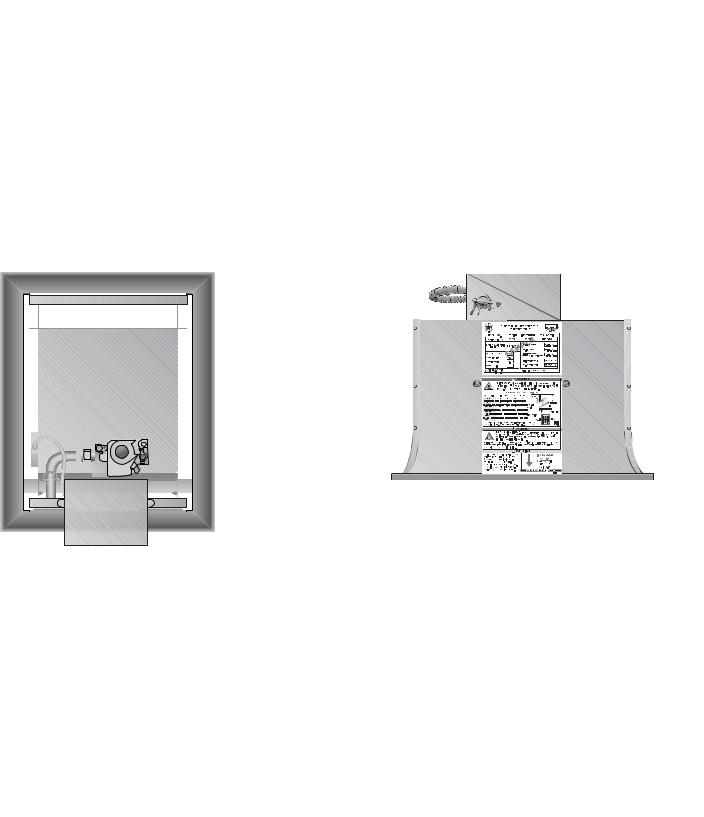
Safety warning labels must be maintained on the infra-red heater. Illustrations of the safety labels, and their locations, are pictured below.
|
|
DAYTON INFRA-RED RADIANT HEATER |
|
|
|
|
|
FOR INDOOR INSTALLATION ONLY |
|
|
|
MODEL NO. |
|
INPUT BTU/H |
FOR USE WITH |
||
3E133E |
|
60,000 |
NAT GAS |
|
|
DESIGN COMPLIES WITH: |
|
Manifold Pressure |
6.0in. |
W.C.P. |
|
ANS Z83.19-2001-GAS FIRED HIGH INTENSITY INFRA-RED HTR. |
|
|
|||
|
|
|
ax. Inlet Pressure |
14.0in. |
W.C.P. |
VOLTS AC |
60Hz |
120V |
in. Inlet Pressure for |
|
W.C.P. |
|
|
0.1 |
Purpose of Input Adjustment 7.0in. |
||
AMPS - Starting |
|
|
|
||
AMPS - Running |
SAMPLEMin. Mounting Angle |
20 DEGREES |
|||
0.1 |
|
|
|
||
Heater Type: |
C1 |
Max. Mounting Angle |
35 DEGREES |
||
MANUFACTURED FOR: |
|
Serial No. 0603DETR 21400 0001 |
|
||
DAYTON ELECTRIC MFG. CO. |
|
|
|||
NILES, IL 60714 |
U.S.A. |
|
|
||
Bottom Panel |
|
Rating Plate |
|||
|
|
|
|
||
F/N: LLDR002 |
! WARNING
AVOID SERIOUS INJURY, DEATH OR PROPERTY DAMAGE.
Maintain Clearances to Combustibles to Prevent the Risk of Fire.
Clearances to combustibles must be maintained in order to prevent the ignition of combustible materials. In locations used for the storage of combustible materials, signs must be posted to specify the maximum permissible stacking height to maintain the required clearances from the heater to the combustibles. Signs must either be posted adjacent to the heater thermostats or in the absence of such thermostats in a conspicuous location. Clearances are provided on the heater’s safety labels and in the heater’s Installation & Operation Manual. Refer to applicable ANSI orNFPA-54 Standards or local codes for further information. Post this tag adjacent to the heater’s thermostat or controls before operating the heater.
INSTALLER. READ AND POST THIS NOTICE.
F/N: LL01 - Clearance Safety Tag (Affix adjacent to heater’s thermostat)
F/N: LLDCL002
8
 Loading...