


Operating Instructions & Parts Manual |
3UG73E and 3UG74E |
|
|
Please read and save these instructions. Read carefully before attempting to assemble, install, operate or maintain the product described. Protect yourself and others by observing all safety information. Failure to comply with instructions could result in personal injury and/or property damage! Retain instructions for future reference.
Dayton® Electric Utility
Heaters
Description
Dayton electric utility heaters are designed to meet a variety of heating requirements by switching a few wires located in the base of the unit. Heat output ranges from 6,396 to 17,065 BTU per hour. Features horizontal and vertical flow (horizontal air throw approximately 18 ft.), built-in thermostat, and high-limit thermal cutout.
Specifications |
|
|
|
|
|
|
|
|
|||
|
|
|
|
|
Amps @ |
|
Temp. |
BTU/Hr. @ |
|
||
Model |
Watts |
Volts |
Phase |
Hz |
240V |
208V |
CFM |
Rise |
240V |
208V |
|
3UG73E* |
5000** |
240/208 |
1 |
60 |
20.9 |
18.0 |
270 |
60˚F |
17,065 |
12,799 |
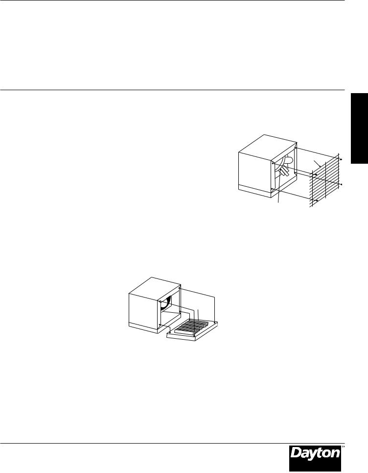
Figure 1 |
|
4165 |
240/208 |
1 |
60 |
17.4 |
15.0 |
270 |
60˚F |
14,215 |
10,659 |
Unpacking |
|
3332 |
240/208 |
1 |
60 |
13.9 |
12.0 |
270 |
60˚F |
11,365 |
8,533 |
|
|
2500 |
240/208 |
1 |
60 |
10.4 |
9.0 |
270 |
60˚F |
8,533 |
6,393 |
Remove the heater from box and |
3UG74E |
5000** |
208 |
1 |
60 |
– |
24.0 |
270 |
60˚F |
– |
17,065 |
inspect for any damage. If it appears |
|
4165 |
208 |
1 |
60 |
– |
20.0 |
270 |
60˚F |
– |
14,215 |
to be damaged, immediately return. |
|
3332 |
208 |
1 |
60 |
– |
16.0 |
270 |
60˚F |
– |
11,365 |
Check the contents of the box to make |
|
2500 |
208 |
1 |
60 |
– |
12.0 |
270 |
60˚F |
– |
8,533 |
|
|
sure it contains one heating unit and |
||||||||||
|
|
|
|
|
|
|
|
|
|
|
|
(*) Can be operated at 208V (see Table 1 for ratings). |
|
|
|
|
one mounting bracket. |
||||||
(**) Heater is shipped from factory wired for these wattages. Heater can be field adjusted to the other wattages (refer to “Adjusting the Heat Output” on page 4).
14”
121/2”
NOTE: Min. Clearance To Ceiling
When Not Using Mounting
Brackets Is 15/8”
Front View
Figure 2 – Dimensions
Minimum
Distance to Wall
13” |
|
||
|
111/4” |
|
|
|
51/2” |
|
|
|
|
24” |
|
|
Mounting |
Minimum Distance |
|
13/4” |
from Discharge |
||
Location |
|||
to Any Object |
|||
|
|
||
|
1/2”, 3/4” |
6’ Minimum |
|
|
Distance to Floor |
||
|
|
||
Maximum Mounting Height for:
Vertical Air Delivery Unit = 11’
Horizontal Air Delivery Unit = 8’
Side View
General Safety
Information
When using electric
appliances, basic
precautions should always be followed to reduce the risk of fire, electric shock and injury to persons, including the following:
1.Read all instructions before installing or using this heater.
2.This heater is hot when in use. To avoid burns, do not let bare skin touch hot surfaces. Keep combustible materials, such as furniture, pillows, bedding, papers, clothes, etc. and curtains at least 3 feet (0.9 m) from the front of the heater.
3.Extreme caution is necessary when any heater is used by or near children or invalids, and whenever the heater is left operating and unattended.
Form 5S5433 |
Printed in U.S.A. |
06/13 |
|
09663 |
5200-11198-000 |
|
Version 1 |
|
|
ISS 1.0 |
|
|
06/2013 |
|
|
|
ECR 39427 |
E N G L I S H
E S P A
Ñ
O
L
F
R A N
Ç
A
I
S

Dayton Operating Instructions and Parts Manual |
3UG73E and 3UG74E |
|
|
|
|
Dayton® Electric Utility Heaters
E |
General Safety |
N |
Information |
GL |
(Continued) |
I |
4. Do not operate any heater after |
|
it malfunctions. Disconnect power |
||
S |
||
at main service panel and have |
||
H |
||
heater inspected by a reputable |
||
|
||
|
electrician before using. |
|
|
5. Do not use outdoors. |
|
|
6. To disconnect heater, turn controls |
|
|
to off, and turn off power to heater |
|
|
circuit at main service panel. |
|
|
7. Do not insert or allow foreign objects |
|
|
to enter any ventilation or exhaust |
|
|
opening as this may cause an electric |
|
|
shock, fire, or damage to the heater. |
|
|
8. To prevent a possible fire, do not |
|
|
block air intake or exhaust in |
|
|
any manner. |
|
|
9. A heater has hot and arcing or |
|
|
sparking parts inside. Do not use it |
|
|
in areas where gasoline, paint, or |
|
|
flammable liquids are used or stored. |
|
|
10. Use this heater only as described |
|
|
in this manual. Any other use not |
|
|
recommended by the manufacturer |
|
|
may cause fire, electric shock, or |
|
|
injury to persons. |
|
|
11.This heater is provided with a red |
|
|
alarm light that will illuminate only |
|
|
if the heater has turned off as a |
|
|
result of overheating. If you see the |
|
|
light on, immediately turn the heater |
|
|
off and inspect for any objects on |
|
|
or adjacent to the heater that |
|
|
may have blocked the airflow or |
|
|
otherwise caused high temperatures |
|
|
to have occurred. DO NOT OPERATE |
|
|
THE HEATER WITH THE ALARM |
|
|
LIGHT ILLUMINATING. |
12.This heater is intended for comfort heating applications and not intended for use in special environments. Do not use in damp or wet locations such as marine or greenhouse or in areas where corrosive or chemical agents are present.
13.When installing, see INSTALLATION INSTRUCTIONS for additional warnings and precautions.
14.For safe and efficient operation, and to extend the life of your heater, keep your heater clean. See MAINTENANCE INSTRUCTIONS.
SAVE THESE
INSTRUCTIONS
Installation
Instructions
To prevent a possible fire,
injury to persons or damage to the heater, adhere to the following:
1.Disconnect all power coming to heater at main service panel before wiring or servicing.
2.All wiring procedures and connections must be in accordance with the National and Local Codes having jurisdiction and the heater must be grounded.
3.Verify the power supply voltage coming to heater matches the ratings as shown on the heater nameplate.
Energizing heater at a voltage greater
than the voltage printed on the nameplate will damage the heater and void the warranty and could cause a fire.
High temperature, risk of fire; keep
electrical cords, drapery, furnishings, and other combustibles at least 3 feet (0.9 m) from front of heater. Do not install heater behind doors, below towel racks, or in an area where it is subject to being blocked by furniture, curtains or storage materials. Hot air from the heater may damage certain fabrics and plastics.
4.To reduce the risk of fire, do not store or use gasoline or other flammable vapors and liquids in the vicinity
of the heater.
5.When heater is to be wall or ceiling mounted, the anchoring provisions must be of sufficient strength to support the total weight of the heater plus the weight of the mounting provisions. Failure to properly secure the supporting members of the building structure could allow the heater to fall.
6.The following minimum clearances must be maintained:
For vertical airflow, bottom of heater to floor: 6’ (1829 mm) minimum,
11’ (3353 mm) maximum.
Horizontal aiflow, bottom of heater to floor: 6’ (1829 mm) minimum,
8’ (2438 mm) maximum.
Sides of heater to adjacent wall: Airflow from horizontal to 45° downward: 13” (330 mm) - Airflow from 45° downward to straight down 48” (1219 mm).
Discharge to any object: 36” (915 mm) minimum.
7.Do not use this heater for dry out as the paint, plaster, sawdust and drywall sanding dust will permanently damage the heater
and must be kept out of the heater.
2

Dayton Operating Instructions and Parts Manual
Models 3UG73E and 3UG74E
Installation Instructions (Continued)
LOCATING HEATER
Install heater out of traffic areas, maintaining clearances stated in Figure 2. The direction of airflow should not be restricted (ie: by columns or machinery) and the airflow should wipe exposed walls, rather than blowing directly at them. When more than one heater is used in an area, the heaters should be arranged so that the air discharge of each heater supports the airflow of
the others to provide best circulation of warm air, as indicated in Figure 3.
Figure 3
MOUNTING THE BRACKET
Refer to Figures 4a and 4b.
1.Locate a stud in the ceiling joist.
2.Remove the mounting bracket from the heating unit by loosening bracket screws with a wrench and slipping the handle off over the screw heads.
3.Place a washer on screws before inserting through the holes in the mounting bracket, and screw them securely into a ceiling joist.
NOTE: If you want to swivel the heater either to the right or left, adding a washer to both sides of the bracket is recommended. A longer lag bolt may be required to properly secure the unit (see Figure 4a).
Ceiling Joist
Washer 

Bracket
3/8” Diameter Lag Bolt
Figure 4a – Single-Screw Mounting
Ceiling Joist
Washer |
Bracket |
|
3/8” Diagonal Lag Bolt
Figure 4b – Double-Screw Mounting
4.Tighten screws enough to securely hold heating unit with airflow pointed in proper direction.
HANGING THE HEATER
1.Attach the heating unit to the mounting bracket.
2.Lift the heater up and into the mounting bracket.
3.Align the bracket screws with the keyhole slots in the mounting bracket.
4.If the heater is to be tilted, it must be positioned in the keyhole slots (see Figure 5).
Use bottom keyhole |
Remove screw |
|
slots if heater is to |
||
to open door |
||
be tilted down |
||
|
||
Figure 5 |
|
5.Tighten the bracket screws with a wrench so the unit is securely suspended at desired horizontal or vertical level.
CONNECTING THE POWER
1.Remove the screw from the front of the unit to connect the power to the heater.
2.Attach the cable connector to the unit (see Figure 6) and slide the 10 gauge wire through the cable connector.
|
|
|
Conduit |
|
|
|
|
|
|||||||||||||||
|
|
|
Connector |
|
|
|
|
|
|||||||||||||||
Conduit |
|
|
|
||||||||||||||||||||
|
|
|
|
|
|
|
|
|
|
|
3’ |
|
|
|
|
|
|
|
|||||
|
|
|
|
|
|
|
|
|
|
|
|
|
|
|
|
|
|||||||
|
|
|
|
|
|
|
|
|
|
|
|
|
|
|
|
|
|
|
|
||||
|
|
|
|
|
|
|
|
|
|
|
|
|
|
|
|
|
|
|
|
|
|
|
|
Flexible Conduit |
|
|
|
|
|
|
|
|
|
|
|
|
|||||||||||
|
|
Flexible Conduit |
|
||||||||||||||||||||
|
|
|
|
|
|
|
|
|
|
|
|
Connector |
2 |
|
|
||||||||
|
|
|
|
|
|
|
|
|
|
|
|
|
|
|
|
|
|
|
|
|
|
|
|
|
|
|
|
|
|
|
|
|
|
|
|
|
|
|
|
|
|
|
|
|
|
||
|
|
|
|
|
|
|
|
|
|
|
|
|
|
1 |
|
|
|
|
|
|
|||
|
|
|
|
|
|
|
|
|
|
|
|
|
|
|
|
|
|
|
|
|
|
||
|
|
|
|
|
|
|
|
|
|
|
|
|
|
|
|
|
|
|
|
|
|
|
|
Flexible |
|
|
|
|
|
|
|
|
|
|
|
|
|
|
|
|
|
|
|
|
|||
|
|
|
|
|
|
|
|
|
Flexible NM |
|
|
|
|||||||||||
|
NM Cable |
|
|
|
|
|
|
|
|
|
Cable Connector |
|
|||||||||||
|
|
|
|
|
|
|
|
|
|
|
|
|
|
|
|
|
|
|
|
|
|
|
|
|
|
|
|
|
|
|
|
|
|
|
|
|
|
|
|
|
|
|
|||||
|
|
|
|
|
|
|
|
|
2 |
|
|
|
|
|
|
|
|||||||
|
|
1 |
|
|
|
|
|
||||||||||||||||
|
|
|
|
|
|
|
|
|
|
|
|
|
|
|
|
|
|
|
|
|
|
|
|
|
|
|
|
|
|
|
|
|
|
|
|
|
|
|
|
|
|
|
|
|
|
||
|
|
3 |
|
|
|
|
|
|
|
|
|
|
|
|
|
|
|
|
|
||||
|
|
|
|
|
|
|
|
|
|
|
|
|
|
|
4 |
|
|
|
|
||||
|
|
|
|
|
|
|
|
|
|
|
|
|
|
|
|
|
|||||||
Figure 6 – Connectors, cable, and hardware used to wire the heater
E N G L I S H
3

Dayton Operating Instructions and Parts Manual |
3UG73E and 3UG74E |
|
|
|
|
Dayton® Electric Utility Heaters
E |
Installation |
|
N |
Instructions |
|
GL |
(Continued) |
|
I |
NOTE: For certain applications, conduit |
|
may be required (see Figure 6). Check |
||
S |
||
local electrical codes. If you run the |
||
H |
||
wiring in conduit and wish to be able |
||
|
||
|
to turn the heater be sure to purchase |
|
|
enough flexible conduit to allow the |
|
|
heater to be turned. |
|
|
3. Connect the wire to the power block |
|
|
located in the base of the heater |
|
|
(see Figure 7). |
|
|
Bottom |
|
|
View |
|
|
Power |
|
|
Terminal Block |
|
|
2 |
|
|
L |
|
|
Black |
|
|
1 |
|
|
L |
White |
Green (or |
|
|
Figure 7 |
Bare Copper) |
|
NOTE: Unit is 240/208 volts. When wiring a two conductor cable with ground, the white wire must be marked black by adding a piece of black electrical tape to the wire near
the point of connection.
NOTE: To decrease the heat output of the heating unit, see Table 1 and Figure 9.
4.Turn on the power at the main service panel.
WIRING
|
|
1 |
HI |
7 |
RD |
|
2 |
LIMIT |
8 |
YL |
|
3 |
|
9 |
|
4 |
ELEMENT |
10 |
|
BLU |
|
5 |
11 |
|
|
6 |
FAN |
12 |
|
|
BLK |
CONT. |
||
|
|
|
|
|
|
|
|
WATTAGE CHANGE |
|
|
|
|
TERMINAL BOARD |
|
C D |
A |
B |
|
|
THERMOSTAT |
|
|
|
|
GROUND |
|
|
|
FAN |
|
|
ALARM LIGHT |
MOTOR |
|
|
|
|
|
|
POWER
TERMINAL
BLOCK
L1 L2
FIELD
WIRING
208/240V - 3UG73E 208V - 3UG74E
Figure 9 – Wiring Diagram
Table 1 – Heat Output Adjustments
NOTE:
1.Do not move blue wire at L1. (Table 1 refers to blue wire at terminal T.)
2.It is recommended that #10 AWG wire be used in
all installations to provide for possible future reconnection at the higher wattage. Refer to NEC (National Electrical Code) for maximum run length to minimize voltage drop to 3% max. Circuit runs exceeding 100 ft. may require larger conductor size).
3.Wires #2, #3, & #4 should be routed through indicated element jumper wire eliminating use of wire tie.
|
|
|
|
Max |
Heater |
Move Jumpers |
Model |
BTU/Hr. |
Volts |
Watts |
Fuse Size |
Amps |
from C-D to A-B |
3UG73E |
17065 |
240 |
5000 |
30 |
20.9 |
None |
|
14215 |
240 |
4165 |
25 |
17.4 |
Blue |
|
11365 |
240 |
3332 |
20 |
13.9 |
Blue & Yellow |
|
8533 |
240 |
2500 |
15 |
10.4 |
Blue, Yellow & Red |
|
12799 |
208 |
3750 |
25 |
18.0 |
None |
|
10659 |
208 |
3123 |
20 |
15.0 |
Blue |
|
8533 |
208 |
2500 |
15 |
12.0 |
Blue & Yellow |
|
6393 |
208 |
1874 |
15 |
9.0 |
Blue, Yellow & Red |
3UG74E |
17065 |
208 |
5000 |
30 |
24.0 |
None |
|
14215 |
208 |
4165 |
25 |
20.0 |
Blue |
|
11365 |
208 |
3332 |
20 |
16.0 |
Blue & Yellow |
|
8533 |
208 |
2500 |
15 |
12.0 |
Blue, Yellow & Red |
Figure 8 – Adjustable Louvers
4
Dayton Operating Instructions and Parts Manual
Models 3UG73E and 3UG74E
Operation
Instructions
1.Heater must be properly installed before operation.
2.After heater is completely assembled, rotate thermostat knob counterclockwise until control stops. This
is the minimum heat setting.
3.Turn power supply to heater “ON” at main service panel.
4.Heater should not operate. If it operates disconnect power and recheck wiring.
5.Rotate thermostat clockwise until it stops (maximum heat setting).
6.Heater should turn on after a brief delay (see “Automatic Fan Delay”). If heater and fan do not come on, disconnect power and check wiring.
NOTE: The first time you operate the unit, it may smoke slightly. This is due to the residual cleaning agents used to clean the element when the heater is manufactured. This is normal and does not indicate a problem with the unit. This condition will stop after the heater has been in operation for a few minutes.
7.Allow heater to continue to operate until room temperature reaches desired comfort level. Then rotate thermostat knob counterclockwise slowly until thermostat clicks off. (Note that the fan delay will keep the fan running until the elements cool.) Heater will cycle on and off to maintain room temperature.
8.It may be necessary to readjust thermostat until exact comfort level is attained. Rotation in the clockwise direction will increase the amount of time the heater will produce heat. Rotation in the counterclockwise direction will reduce the amount
of time the heater is on.
AUTOMATIC FAN DELAY
The heaters have an automatic fan delay. When the thermostat calls for heat, fan action is delayed momentarily until the heating element warms. This prevents the circulation of cold air. When the heater raises the temperature of the room to the thermostat set point, the heating element is turned off but the fan will continue to run until the heating element cools down. This prevents exposing the unit to residual heat, provides a higher comfort level and prolonged element life.
Heating
Element
Figure 10
THERMAL SAFETY LIMIT
The heaters are equipped with a thermal cutout which will automatically shut off the heater in the event of overheating.
The heater will turn on when the abnormal temperature returns to normal. Should the unit overheat and cause the thermal limit to cycle, a red alarm light will illuminate to alert
the user that the heater is off and the cause of the overheating should be determined and corrective action should be taken before further operation.
Protective
Grill
Fan and Motor
Figure 11
NOTE: If the unit is installed in an area where the temperature is below 50°F, the fan may cycle on and off until the temperature in the room rises above 50°F, this is normal and does not indicate a problem with the unit. As soon as the heater warms the air in the room above 50°F, the unit will operate normally.
ADJUSTING AIRFLOW DIRECTION
1.Turning the Unit – If the unit has been installed with a single lag bolt, as shown in Figure 4a, simply turn the entire unit as needed to adjust airflow.
2.Tilting the unit – Loosen the bracket screws, tilt the heater to the desired position, and retighten the bracket screws (see Figure 5).
NOTE: To tilt the heater it must be mounted in bottom keyhole slots of mounting brackets to maintain adequate clearance and prevent possible overheating.
E N G L I S H
5
Dayton Operating Instructions and Parts Manual |
3UG73E and 3UG74E |
|
|
|
|
Dayton® Electric Utility Heaters
E |
Operation |
|
N |
Instructions |
|
GL |
(Continued) |
|
I |
3. Adjusting the louvers to the desired |
|
position (see Figure 8). |
||
S |
||
|
HNOTE: The louvers are designed so they cannot be completely closed.
Do not attempt to defeat this feature, damage to the unit can result.
ADJUSTING HEAT OUTPUT
Increase or decrease heat output by switching wires at the wattage change terminal board. The heaters are factory wired to deliver a heat output of 17,065 BTU per hour. Should your particular application require less heat output, refer to Table 1 and change the wires at the wattage change terminal board as shown in Wiring Diagram (see Figure 9).
To prevent possible electric shock,
disconnect power to the heater at the main service panel before attempting to adjust the heat output of this unit.
It is important to keep this heater clean. Your heater will give you years of service and comfort with only minimum care. To assure efficient operation follow the simple instructions below.
All servicing beyond simple cleaning
that requires disassembly should be performed by qualified service personnel.
To reduce the risk of fire and electric
shock or injury, disconnect all power coming to heater at main service panel and check that the element is cool before servicing or performing maintenance.
USER CLEANING INSTRUCTIONS
1.After the heater has cooled, a vacuum cleaner with brush attachment may be used to remove dust and lint from exterior surfaces of the heater including the grille openings.
2.With a damp cloth, wipe dust and lint from grille and exterior surfaces.
3.Return power to heater and check to make sure it is operating properly.
MAINTENANCE CLEANING
INSTRUCTIONS
(To be performed only by Qualified Service Personnel)
At least annually, the heater should be cleaned and serviced by a qualified service person to assure safe and efficient operation. After completing the cleaning and servicing, the heater should be fully reassembled and checked for proper operation.
Maintenance
Instructions
It is important to keep this heater clean. Your heater will give you years of service and comfort with only minimum care. To assure efficient operation follow the simple instructions below.
All servicing beyond simple cleaning
that requires disassembly should be performed by qualified service personnel.
To reduce the risk of fire and electric
shock or injury, disconnect all power coming to heater at main service panel and check that the element is cool before servicing or performing maintenance.
USER CLEANING INSTRUCTIONS
1.After the heater has cooled, a vacuum cleaner with brush attachment may be used to remove dust and lint from exterior surfaces of the heater including the grille openings.
2.With a damp cloth, wipe dust and lint from grille and exterior surfaces.
3.Return power to heater and check to make sure it is operating properly.
MAINTENANCE CLEANING
INSTRUCTIONS
(To be performed only by Qualified Service Personnel)
At least annually, the heater should be cleaned and serviced by a qualified service person to assure safe and efficient operation. After completing the cleaning and servicing, the heater should be fully reassembled and checked for proper operation.
6

Dayton Operating Instructions and Parts Manual
For Repair Parts, call 1-800-Grainger
24 hours a day – 365 days a year
Please provide following information:
-Model number -Serial number (if any)
-Part description and number as shown in parts list
 10
10
2 |
9 |
|
8
15
7 
14
16

 6
6
17
5
13
Figure 12 – Repair Parts Illustration for Electric Utility Heaters
3UG73E and 3UG74E
|
|
E |
|
|
N |
|
|
G |
|
|
L |
|
|
I |
3 4 |
|
S |
1 |
H |
|
|
12 |
|
|
|
11
Repair Parts List for Electric Utility Heaters
Reference |
|
Part Number for Models: |
|
Number |
Description |
3UG73E and 3UG74E |
Quantity |
1 |
Element for 3UG73E |
302006807 |
1 |
|
Element for 3UG74E |
302006847 |
1 |
2 |
Motor |
3900-2008-000 |
1 |
3 |
Fan Delay Control |
410148000 |
1 |
4 |
High Temperature Limit Control |
410027000 |
1 |
5 |
Thermostat |
5813-2050-000 |
1 |
6 |
Thermostat Knob |
3301-2014-006 |
1 |
7 |
Motor Mount |
310914001 |
1 |
8 |
Fan Blade |
1210-2017-000 |
1 |
9 |
Ceiling Bracket |
310876002 |
1 |
10 |
Wire Guard |
312056802 |
1 |
11 |
Louver |
3503-2004-009 |
4 |
12 |
Bezel Assembly |
1219-0414-000 |
1 |
13 |
Cover (Access Door) |
310104902 |
1 |
14 |
Bracket Screw |
402029008 |
2 |
15 |
Cover Wrap Assembly |
200193902 |
1 |
16 |
Control Box Assembly |
200161902 |
1 |
17 |
Power Terminal Block |
5823-0004-005 |
1 |
|
|
|
|
7

Dayton Operating Instructions and Parts Manual |
3UG73E and 3UG74E |
|
|
|
|
Dayton® Electric Utility Heaters
E |
LIMITED WARRANTY |
|
N
GDAYTON ONE-YEAR LIMITED WARRANTY. DAYTON® ELECTRIC UTILITY HEATERS, MODELS COVERED IN THIS MANUAL, ARE WARRANTED BY DAYTON ELECTRIC MFG. CO. (DAYTON) TO THE ORIGINAL USER AGAINST DEFECTS IN WORKMANSHIP
L |
OR MATERIALS UNDER NORMAL USE FOR ONE YEAR AFTER DATE OF PURCHASE. ANY PART WHICH IS DETERMINED TO |
|
I |
||
BE DEFECTIVE IN MATERIAL OR WORKMANSHIP AND RETURNED TO AN AUTHORIZED SERVICE LOCATION, AS DAYTON |
||
S |
||
DESIGNATES, SHIPPING COSTS PREPAID, WILL BE, AS THE EXCLUSIVE REMEDY, REPAIRED OR REPLACED AT DAYTON’S |
||
|
HOPTION. FOR LIMITED WARRANTY CLAIM PROCEDURES, SEE “PROMPT DISPOSITION” BELOW. THIS LIMITED WARRANTY GIVES PURCHASERS SPECIFIC LEGAL RIGHTS WHICH VARY FROM JURISDICTION TO JURISDICTION.
LIMITATION OF LIABILITY. TO THE EXTENT ALLOWABLE UNDER APPLICABLE LAW, DAYTON’S LIABILITY FOR CONSEQUENTIAL AND INCIDENTAL DAMAGES IS EXPRESSLY DISCLAIMED. DAYTON’S LIABILITY IN ALL EVENTS IS LIMITED TO AND SHALL NOT EXCEED THE PURCHASE PRICE PAID.
WARRANTY DISCLAIMER. A DILIGENT EFFORT HAS BEEN MADE TO PROVIDE PRODUCT INFORMATION AND ILLUSTRATE THE PRODUCTS IN THIS LITERATURE ACCURATELY; HOWEVER, SUCH INFORMATION AND ILLUSTRATIONS ARE FOR THE SOLE PURPOSE OF IDENTIFICATION, AND DO NOT EXPRESS OR IMPLY A WARRANTY THAT THE PRODUCTS ARE MERCHANTABLE, OR FIT FOR A PARTICULAR PURPOSE, OR THAT THE PRODUCTS WILL NECESSARILY CONFORM TO THE ILLUSTRATIONS OR DESCRIPTIONS. EXCEPT AS PROVIDED BELOW, NO WARRANTY OR AFFIRMATION OF FACT, EXPRESSED OR IMPLIED, OTHER THAN AS STATED IN THE “LIMITED WARRANTY” ABOVE IS MADE OR AUTHORIZED BY DAYTON.
Technical Advice and Recommendations, Disclaimer. Notwithstanding any past practice or dealings or trade custom, sales shall not include the furnishing of technical advice or assistance or system design. Dayton assumes no obligations or liability on account of any unauthorized recommendations, opinions or advice as to the choice, installation or use of products.
Product Suitability. Many jurisdictions have codes and regulations governing sales, construction, installation, and/or use of products for certain purposes, which may vary from those in neighboring areas. While attempts are made to assure that Dayton products comply with such codes, Dayton cannot guarantee compliance, and cannot be responsible for how the product is installed or used. Before purchase and use of a product, review the product applications, and all applicable national and local codes and regulations, and be sure that the product, installation, and use will comply with them.
Certain aspects of disclaimers are not applicable to consumer products; e.g., (a) some jurisdictions do not allow the exclusion or limitation of incidental or consequential damages, so the above limitation or exclusion may not apply to you; (b) also, some jurisdictions do not allow a limitation on how long an implied warranty lasts, consequently the above limitation
may not apply to you; and (c) by law, during the period of this Limited Warranty, any implied warranties of implied merchantability or fitness for a particular purpose applicable to consumer products purchased by consumers, may not be excluded or otherwise disclaimed.
Prompt Disposition. A good faith effort will be made for prompt correction or other adjustment with respect to any product which proves to be defective within limited warranty. For any product believed to be defective within limited warranty, first write or call dealer from whom the product was purchased. Dealer will give additional directions. If unable to resolve satisfactorily, write to Dayton at address below, giving dealer’s name, address, date, and number of dealer’s invoice, and describing the nature of the defect. Title and risk of loss pass to buyer on delivery to common carrier. If product was damaged in transit to you, file claim with carrier.
Manufactured for Dayton Electric Mfg. Co., 100 Grainger Parkway, Lake Forest, Illinois 60045-5201 U.S.A.
Manufactured for Dayton Electric Mfg. Co. Lake Forest, Illinois 60045 U.S.A.
 Loading...