


Dayton 1XJX7, 1XJX8, 1XJX9, 1XJY1, 1XJY2 User Manual
...Operating Instructions & Parts Manual |
1XJX7 thru 1XJX9, and 1XJY1 thru 1XJY4 |
|
|
Please read and save these instructions. Read carefully before attempting to assemble, install, operate or maintain the product described. Protect yourself and others by observing all safety information. Failure to comply with instructions could result in personal injury and/or property damage! Retain instructions for future reference.
Dayton® Direct-Drive
Blowers
Description
Dayton direct-drive blowers are specifically engineered for air-conditioning, heating and ventilating systems where the blower is mounted within a cabinet or plenum chamber. To minimize vibration, 4-point reinforced mounting brackets have been equipped with rubber isolators. Blowers can be mounted in four variable discharge positions. All motors are permanent split capacitor type (with appropriate capacitor attached) with automatic reset thermal protection.
Unpacking
1.Inspect unit for any damage that may have occurred during transit.
2.Shipping damage claim must be filed with carrier.
3.Insure that blower wheel spins freely before installation.
|
Motor Component Recognition |
Dimensions |
E47479 |
|
|
|
|
Wheel Diameter |
|
|
|
|
|
|
|
|
|
|
|
|
|
|
|
|
|
|||||
|
Model |
x Width |
A |
|
B |
|
C |
D |
E |
|||||||||||||||||
|
1XJX7 |
97/16 x 73/16 |
129/16 |
61/8 |
3/4 |
12¾ |
713/16 |
|||||||||||||||||||
|
1XJX8 |
97/16 x 97/16 |
15 |
|
|
|
|
77/32 |
19/16 |
159/32 |
10¼ |
|||||||||||||||
|
1XJX9 |
97/16 x 97/16 |
15 |
|
|
|
|
77/32 |
19/16 |
159/32 |
10¼ |
|||||||||||||||
|
1XJY1 |
11 x 713/16 |
169/16 |
77/8 |
19/32 |
175/16 |
113/8 |
|||||||||||||||||||
|
1XJY2 |
11 x 109/16 |
169/16 |
77/8 |
19/32 |
175/16 |
113/8 |
|||||||||||||||||||
|
1XJY3 |
13 x 9½ |
199/32 |
87/8 |
15/8 |
205/16 |
133/8 |
|||||||||||||||||||
|
1XJY4 |
13 x 9½ |
199/32 |
91/16 |
15/8 |
205/16 |
133/8 |
|||||||||||||||||||
|
|
|
|
|
|
|
|
|
|
|
|
|
|
|
|
|
|
|
|
|
|
|
|
|
|
|
|
|
|
|
|
|
A |
|
|
|
|
|
|
|
|
|
|
|
|
|
|
|
|
|
|||
|
|
|
|
|
|
|
|
|
|
|
|
|
|
|
|
|
|
|
|
|
G |
|
|
|
||
|
|
|
|
|
|
|
|
|
|
|
|
|
|
|
|
|
|
|
|
|
|
|
|
|||
|
|
|
|
|
|
|
|
|
|
|
|
|
|
|
|
|
|
|
|
|
|
|||||
|
|
|
|
|
|
|
|
|
|
|
|
|
|
|
|
|
|
|
|
|
|
|
|
|
|
|
|
|
|
|
|
|
|
|
B |
|
|
|
|
|
|
|
|
|
|
|
|
|
|
|
|
|
|
|
|
|
|
|
|
|
|
|
|
|
|
|
|
|
|
|
|
|
|
|
|
|
|
|
|
|
|
|
|
|
|
|
|
|
|
|
|
|
|
|
|
|
|
|
|
|
|
|
|
||||
|
|
|
|
|
|
|
|
|
|
|
C |
|
|
|
|
|
|
|
|
|
|
|||||
|
|
|
|
|
|
|
|
|
|
|
|
|
|
|
|
|
|
|
|
|
|
|
|
|
|
|
|
|
D |
|
|
|
|
|
|
|
|
|
|
|
|
|
|
|
|
|
|
|
|
|
|
|
|
|
|
|
|
|
|
|
|
|
|
|
|
|
|
|
|
|
|
|
|
|
|
|
|
|
|
|
|
|
|
|
|
|
|
|
|
|
|
|
|
|
|
|
|
E |
|
|
|
|
|
|
|
|
|
|
|
|
|
|
|
|
|
|
|
|
|
|
|
|
|
|
|
F |
|
|
|
|
|
|
|
|
|
|
|
|
|
|
|
|
|
|
|
|
|
|
|
|
|
|
|
|
|
|
|
|
|
|
|
|
|
|
|
|
|
|
|
|
|
|
|
I |
|
|
|
|
|
|
|
|
|
|
|
|
||
|
|
|
|
|
|
|
|
|
|
|
|
|
|
|
|
|
|
|
|
|
|
|
|
|
|
|
|
|
|
|
|
|
|
|
|
|
|
|
|
|
|
|
|
|
|
|
|
|
|
|
|
|
|
Figure 1 – Dimensions |
|
|
|
|
|
|
|
|
|
|
|
|
||||||||||||||
|
|
|
|
|
|
|
|
|
|
|
|
|
H |
|
||||||||||||
General Safety Information |
|
|
|
|
|
|
|
|
|
|
||||||||||||||||
|
|
|
1. Blower should be installed |
and |
|
|||||||||||||||||||||
|
|
|
|
|
Disconnect power |
|
serviced by a qualified technician |
|||||||||||||||||||
|
|
|
|
|
||||||||||||||||||||||
|
|
|
|
|
source before |
|
|
|
|
|
|
|
|
only. |
|
|
|
|
|
|
|
|
||||
|
|
|
|
|
|
|
|
|
|
|
|
|
|
|
|
|
|
|
|
|||||||
installing or servicing. Failure to |
|
|
|
|
|
|
|
2. Follow all local electrical and safety |
||||||||||||||||||
disconnect power source can result |
|
|
|
|
|
|
|
|||||||||||||||||||
|
|
|
|
|
|
|
|
codes, as well as the National |
|
|||||||||||||||||
in fire, shock or serious injury. |
|
|
|
|
|
|
|
|
|
|||||||||||||||||
Electrical Code (NEC) and the
Occupational Safety and Health Act
(OSHA) in the United States.
F |
G |
H |
I |
71/8 |
9¾ |
91/8 |
619/32 |
89/16 |
125/16 |
1113/16 |
6½ |
89/16 |
125/16 |
1113/16 |
6½ |
95/8 |
11½ |
10½ |
6 |
95/8 |
141/16 |
131/16 |
6 |
119/16 |
135/16 |
123/16 |
811/16 |
119/16 |
135/16 |
123/16 |
85/16 |
3.Motor must be securely and adequately grounded. This can be accomplished by wiring with a grounded, metal-clad raceway system by using a separate ground wire connected to the bare metal of the motor frame, or other suitable means.
4.Always disconnect power source before working on or near a motor or its connected load. Lock it in the open position and tag to prevent unexpected application of power.
5.In accordance with OSHA requirements, guarding is required if blower is mounted less than 7 feet above floor or where workers have access.
6.Be careful when touching the exterior of an operating motor; it may be hot enough to cause injury. With modern motors, this condition is normal as they are built to operate at higher temperatures.
Form 5S5843 |
Printed in China |
|
09670 |
|
1007/240/VCPVP |
E N G L I S H
E S P A
Ñ
O
L
F
R A N
Ç
A
I
S
Dayton Operating Instructions and Parts Manual |
1XJX7 thru 1XJX9, and 1XJY1 thru 1XJY4 |
|
|
|
|
Dayton® Direct-Drive Blowers
E |
General Safety Information |
||
(Continued) |
|||
N |
|
|
Do not touch motor. |
|
|
||
G |
|
|
It may be hot |
|
|
||
L |
enough to cause injury. |
||
I |
7. Protect power cable from coming into |
||
S |
contact with sharp objects. |
||
H8. Do not kink power cable and never allow cable to come in contact with oil, grease, hot surfaces or chemicals.
9.Make certain that the power source conforms to the requirements of your equipment.
Do not use in a flammable or
explosive atmosphere.
Installation
1.Attach the housing supports (ordered separately) to the housing in the desired discharge position.
For safety, a lockable disconnect
switch should be located near blower so power can be positively disconnected while installing or servicing the fan.
Blower frame and motor must be
electrically grounded to a suitable electrical ground such as a grounded metallic raceway or ground wire system. Be sure the motor to housing ground wire is secure.
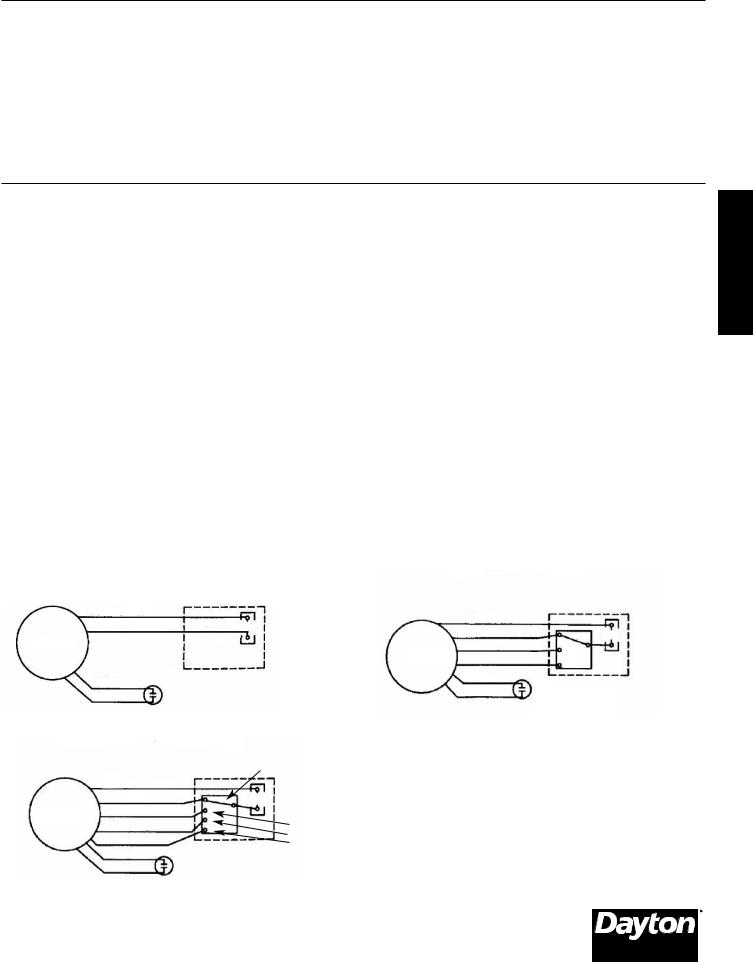
2.Wiring connections:
a.For Models 1XJX7 and 1XJX8 connect the two leads to the appropriate power source.
b.For Models 1XJX9, 1XJY1, 1XJY2, 1XJY3 and 1XJY4, refer to Figure 2, page 3 for wiring.
NOTE: The purple lead in the wiring diagrams must always be used as one of the electrical connections. All leads not used must be “dead ended” (taped off).
3. Unit is ready for operation.
Specifications and Performance
Operation
After the blower is installed and all duct work is re-attached, measure the current input to the motor and compare with the nameplate rating of the motor (See “Specifications and Performance”) to determine if the motor is operating under safe load conditions.
Make certain that the blower is
operating within the static pressure limits shown in the “Specification and Performance” chart; if not, motor overload will result.
Maintenance
Do not depend on any switch as the
sole means of disconnecting power when installing or servicing the fan. If the power disconnect is out-of-sight, lock it in the open position and tag to prevent application of power. Failure to do so may result in fatal electrical shock.
LUBRICATION
The motor bearings are permanently lubricated ball-bearings.
|
|
|
|
CFM Air Delivery @ RPM Shown |
|
|
|
|
|
|
||||
|
Wheel |
Wheel |
.300” |
.400” .500” .600” .700” .800” |
.900” |
No. of |
Motor |
|
Volts |
Full Load |
||||
Model |
Dia. |
Width |
SP |
SP |
SP |
SP |
SP |
SP |
SP |
Speeds |
RPM |
HP |
60 Hz |
Amps |
|
|
|
|
|
|
|
|
|
|
|
|
|
|
|
1XJX7 97/16“ |
73/16” |
1009 |
1005 |
1001 |
929 |
838 |
692 |
– |
1 |
1070 |
1/6 |
115 |
3.7 |
|
1XJX8 |
97/16 |
97/16 |
1457 |
1340 |
1319 |
1301 |
1230 |
1117 |
715 |
1 |
986 |
1/4 |
115 |
4.9 |
|
97/16 |
97/16 |
1638 |
1610 |
1545 |
1457 |
1358 |
1225 |
1050 |
4 |
1085 |
1/3 |
115 |
6.9 |
1XJX9 |
97/16 |
97/16 |
1516 |
1496 |
1437 |
1373 |
1320 |
1139 |
926 |
4 |
1040 |
1/3 |
115 |
6.9 |
97/16 |
97/16 |
1368 |
1310 |
1280 |
1256 |
1185 |
1052 |
826 |
4 |
937 |
1/3 |
115 |
6.9 |
|
|
97/16 |
97/16 |
1132 |
1101 |
1083 |
1046 |
1012 |
896 |
813 |
4 |
858 |
1/3 |
115 |
6.9 |
2
Dayton Operating Instructions and Parts Manual
Models 1XJX7 thru 1XJX9, and 1XJY1 thru 1XJY4
Specifications and Performance (Continued)
|
|
|
|
|
|
|
|
CFM Air Delivery @ RPM Shown |
|
|
|
|
|
|
||||||||||
|
|
|
Wheel |
Wheel |
.800” |
.900” |
1.000” 1.100” |
1.200” |
1.250” 1.300” |
No. of |
Motor |
|
Volts |
Full Load |
||||||||||
Model |
Dia. |
Width |
SP |
SP |
SP |
SP |
SP |
SP |
SP |
Speeds |
RPM |
HP |
60 Hz |
Amps |
||||||||||
|
|
|
|
|
|
|
|
|
|
|
|
|
|
|
|
|
|
|
|
|
|
|
|
|
|
|
|
11“ |
713/16” |
1857 |
|
1751 |
1654 |
1521 |
|
1188 |
938 |
– |
4 |
1060 |
1/2 |
115 |
9.0 |
||||||
1XJY1 |
11 |
|
713/16 |
1706 |
|
1632 |
1546 |
1381 |
|
1033 |
863 |
– |
4 |
1035 |
1/2 |
115 |
9.0 |
|||||||
11 |
|
713/16 |
1524 |
|
1458 |
1393 |
1208 |
|
925 |
841 |
– |
4 |
989 |
1/2 |
115 |
9.0 |
||||||||
|
|
|
11 |
|
713/16 |
1327 |
|
1279 |
1162 |
1049 |
|
846 |
622 |
– |
4 |
946 |
1/2 |
115 |
9.0 |
|||||
|
|
|
11 |
|
109/16 |
– |
2016 |
1864 |
1704 |
|
1399 |
1217 |
1171 |
4 |
1100 |
3/4 |
115 |
9.0 |
||||||
1XJY2 |
11 |
|
109/16 |
– |
1925 |
1776 |
1589 |
|
1255 |
1184 |
1122 |
4 |
1080 |
3/4 |
115 |
9.0 |
||||||||
|
|
|
11 |
|
109/16 |
– |
1745 |
1636 |
1430 |
|
1209 |
1128 |
1074 |
4 |
1050 |
3/4 |
115 |
9.0 |
||||||
|
|
|
11 |
|
109/16 |
– |
1587 |
1474 |
1345 |
|
1152 |
1110 |
880 |
4 |
1027 |
3/4 |
115 |
9.0 |
||||||
|
|
|
|
|
|
|
|
|
|
|
|
|
|
|
|
|
|
|
|
|
||||
|
|
|
|
|
|
|
|
CFM Air Delivery @ RPM Shown |
|
|
|
|
|
|
||||||||||
|
|
|
Wheel |
Wheel |
1.200” |
1.300” |
1.400” 1.500” |
1.600” |
1.700” 1.800” |
No. of |
Motor |
|
Volts |
Full Load |
||||||||||
Model |
Dia. |
Width |
SP |
SP |
SP |
SP |
SP |
SP |
SP |
Speeds |
RPM |
HP |
60 Hz |
Amps |
||||||||||
|
|
|
|
|
|
|
|
|
|
|
|
|
|
|
|
|
|
|
|
|
|
|
|
|
|
|
|
13” |
9½” |
2701 |
|
2522 |
2373 |
2231 |
|
2057 |
1851 |
1655 |
3 |
1097 |
1 |
115 |
15.3 |
||||||
1XJY3 |
13 |
|
9½ |
2480 |
|
2373 |
2218 |
2084 |
|
1910 |
1696 |
1384 |
3 |
1070 |
1 |
115 |
15.3 |
|||||||
|
|
|
13 |
|
9½ |
2248 |
|
2143 |
2032 |
1890 |
|
1685 |
1498 |
– |
3 |
1038 |
1 |
115 |
15.3 |
|||||
|
|
|
13 |
|
9½ |
2553 |
|
2465 |
2316 |
2149 |
|
1957 |
1671 |
1416 |
3 |
1086 |
1 |
230/208 |
7.2/6.9 |
|||||
1XJY4 |
13 |
|
9½ |
2472 |
|
2401 |
2282 |
2116 |
|
1925 |
1680 |
1334 |
3 |
1062 |
1 |
230/208 |
7.2/6.9 |
|||||||
|
|
|
13 |
|
9½ |
2255 |
|
2204 |
2078 |
1959 |
|
1707 |
1333 |
– |
3 |
1039 |
1 |
230/208 |
7.2/6.9 |
|||||
|
|
|
|
|
|
|
|
|
|
|
|
|
|
|
|
|
||||||||
|
|
|
|
|
|
|
|
|
|
|
|
|
|
|
|
|
|
|
|
|
||||
|
|
Single-Speed motor connection Diagram |
|
|
|
|
|
|
|
|
|
|||||||||||||
|
|
|
|
|
|
|
|
|
|
|
3-Speed motor connection diagram |
|
|
|||||||||||
|
|
for models 1XJX7 and 1XJX8 |
|
|
|
|
|
|
|
|
|
|
for models 1XJY3 and 1XJY4 |
|
|
|
||||||||
|
|
|
|
|
|
|
|
|
|
|
|
|
|
|
|
|
|
|
|
|
|
|
||
|
|
|
|
|
|
|
|
|
|
|
|
|
|
|
|
|
|
|
|
|
|
|
||
|
|
|
|
Purple - Common |
|
|
|
|
|
|
|
|
|
|
|
|
Purple - Common |
|
|
|
||||
|
|
|
|
|
Black |
|
|
|
Line |
|
|
|
|
|
|
|
|
|
|
|
|
|
||
|
|
|
|
|
|
|
|
|
|
|
|
|
|
|
|
|
|
Black |
|
High |
Line |
|
||
|
|
Motor |
|
|
|
|
|
|
|
|
|
|
|
|
|
|
|
|
|
|||||
|
|
|
|
|
|
|
|
|
|
|
|
|
|
|
|
|
Blue |
|
|
|||||
|
|
|
|
|
|
|
|
|
|
|
|
|
|
|
|
Motor |
|
Med. |
|
|
||||
|
|
|
|
|
|
|
|
|
|
|
|
|
|
|
|
|
|
|
Red |
|
|
|
||
|
|
|
|
|
|
|
|
|
|
|
|
|
|
|
|
|
|
|
|
Low |
|
|
||
|
|
|
|
|
|
|
|
|
|
|
|
|
|
|
|
|
|
|
|
|
|
|
|
|
|
|
|
|
|
Brown |
|
|
|
|
|
|
|
|
|
|
|
|
|
|
Brown |
|
|
|
|
|
|
|
|
|
Brown |
|
|
|
|
|
|
|
|
|
|
|
|
|
|
Brown |
|
|
|
|
|
|
|
|
|
|
|
|
|
|
|
|
|
|
|
|
|
|
|
|
|
|
|
|
|
|
|
|
|
|
|
|
|
|
|
|
|
|
|
|
|
|
|
|
|
|
||||
|
|
|
|
|
|
|
|
|
|
|
|
|
|
|
|
|
|
|
|
|
|
|
|
|
|
|
|
|
|
|
|
|
|
|
|
|
|
|
|
|
|
|
|
|
|
|
|
|
|
|
4-Speed motor connection diagram |
|
|
|
|
|
|
|
|
|
|
|
|
|
|
|
|
|
||||||
|
for models 1XJX9, 1XJY1 and 1XJY2 |
|
|
|
|
|
|
|
|
|
|
|
|
|
|
|
|
|||||||
|
|
|
|
|
|
|
|
|
|
|
|
|
|
|
|
|
|
|
|
|
|
|
|
|
|
|
|
|
|
|
|
|
|
High |
|
|
|
|
|
|
|
|
|
|
|
|
|
|
|
|
|
|
|
|
Purple - Common |
|
|
|
|
|
|
|
|
|
|
|
|
|
|
|
|
|
||
|
|
|
|
|
Black-1 |
|
Line |
|
|
|
|
|
|
|
|
|
|
|
|
|
|
|
||
|
|
|
Motor |
Yellow-2 |
|
|
Med. High |
|
|
|
|
|
|
|
|
|
|
|||||||
|
|
|
|
|
Orange-3 |
|
|
|
|
|
|
|
|
|
|
|
|
|||||||
|
|
|
|
|
Red-4 |
|
|
|
|
Med. Low |
|
|
|
|
|
|
|
|
|
|
||||
|
|
|
|
|
|
|
|
|
Low |
|
|
|
|
|
|
|
|
|
|
|
|
|||
|
|
|
|
|
Brown |
|
|
|
|
|
|
|
|
|
|
|
|
|
|
|
|
|
|
|
|
|
|
|
|
Brown |
|
|
|
|
|
|
|
|
|
|
|
|
|
|
|
|
|
|
|
|
|
|
|
|
|
|
|
|
|
|
|
|
|
|
|
|
|
|
|
|
|
|||
|
|
|
|
|
|
|
|
|
|
|
|
|
|
|
|
|
|
|
|
|
|
|
|
|
Figure 2 – Wiring Diagrams |
|
|
|
|
|
|
|
|
|
|
|
|
|
|
|
|
|
|||||||
|
|
|
|
|
|
|
|
|
|
|
|
|
|
|
|
|
|
|
|
|
|
|
|
|
E N G L I S H
3

Dayton Operating Instructions and Parts Manual |
1XJX7 thru 1XJX9, and 1XJY1 thru 1XJY4 |
|
|
|
|
For Repair Parts, call 1-800-323-0620
24 hours a day – 365 days a year
Please provide following information:
-Model number -Serial number (if any)
-Part description and number as shown in parts list
E
N
G
L
I
S
H
1
Figure 3 – Repair Parts Illustration for Direct-Drive Blowers
Repair Parts List for Direct-Drive Blowers
Ref. |
|
Part Number for Models: |
|
|
|
|
|
||
No. |
Description |
1XJX7 |
1XJX8 |
1XJX9 |
1XJY1 |
1XJY2 |
1XJY3 |
1XJY4 |
Quantity |
1 |
Motor with capacitor |
2JFF9 |
2JFF3 |
2JFF5 |
2JFF6 |
2JFF4 |
2JFF8 |
2JFF7 |
1 |
4

Dayton Operating Instructions and Parts Manual
Models 1XJX7 thru 1XJX9, and 1XJY1 thru 1XJY4
Troubleshooting Chart
Symptom |
Possible Cause(s) |
Corrective Action |
||
|
|
|
|
|
Excessive noise |
1. Blower wheel striking housing |
1. |
Realign |
|
|
2. |
Foreign material inside housing |
2. |
Clean |
|
3. |
Loose or leaking duct work |
3. |
Repair and/or secure properly |
Insufficient air flow |
1. Motor speed inadequate |
1. |
Make speed adjustment |
|
|
2. |
Leaks in duct work |
2. |
Repair |
|
3. |
Shutters and/or registers closed |
3. |
Open |
|
4. |
Obstruction in system |
4. |
Remove |
|
|
|
|
|
Too much air flow |
1. Motor speed too fast (multi-speed units only) |
1. |
Lower speed |
|
|
2. |
Registers or grilles not installed |
2. |
Install to match system requirements |
|
3. |
Insufficient static pressure |
3. |
Check your static pressure calculations |
|
|
|
|
and correct system accordingly |
|
|
|
|
|
Unit fails to operate |
1. Blown fuse or open circuit breaker |
1. |
Replace fuse or reset circuit breaker |
|
|
2. |
Defective motor/motor capacitor |
2. |
Replace |
E N G L I S H
5

Dayton Operating Instructions and Parts Manual |
1XJX7 thru 1XJX9, and 1XJY1 thru 1XJY4 |
|
|
|
|
Dayton® Direct-Drive Blowers
E |
LIMITED WARRANTY |
|
N
GDAYTON ONE-YEAR LIMITED WARRANTY. DAYTON® DIRECT-DRIVE BLOWERS, MODELS COVERED IN THIS MANUAL, ARE WARRANTED BY DAYTON ELECTRIC MFG. CO. (DAYTON) TO THE ORIGINAL USER AGAINST DEFECTS IN WORKMANSHIP OR
L |
MATERIALS UNDER NORMAL USE FOR ONE YEAR AFTER DATE OF PURCHASE. ANY PART WHICH IS DETERMINED TO BE |
|
I |
||
DEFECTIVE IN MATERIAL OR WORKMANSHIP AND RETURNED TO AN AUTHORIZED SERVICE LOCATION, AS DAYTON |
||
S |
||
DESIGNATES, SHIPPING COSTS PREPAID, WILL BE, AS THE EXCLUSIVE REMEDY, REPAIRED OR REPLACED AT DAYTON’S |
||
|
HOPTION. FOR LIMITED WARRANTY CLAIM PROCEDURES, SEE “PROMPT DISPOSITION” BELOW. THIS LIMITED WARRANTY GIVES PURCHASERS SPECIFIC LEGAL RIGHTS WHICH VARY FROM JURISDICTION TO JURISDICTION.
LIMITATION OF LIABILITY. TO THE EXTENT ALLOWABLE UNDER APPLICABLE LAW, DAYTON’S LIABILITY FOR CONSEQUENTIAL AND INCIDENTAL DAMAGES IS EXPRESSLY DISCLAIMED. DAYTON’S LIABILITY IN ALL EVENTS IS LIMITED TO AND SHALL NOT EXCEED THE PURCHASE PRICE PAID.
WARRANTY DISCLAIMER. A DILIGENT EFFORT HAS BEEN MADE TO PROVIDE PRODUCT INFORMATION AND ILLUSTRATE THE PRODUCTS IN THIS LITERATURE ACCURATELY; HOWEVER, SUCH INFORMATION AND ILLUSTRATIONS ARE FOR THE SOLE PURPOSE OF IDENTIFICATION, AND DO NOT EXPRESS OR IMPLY A WARRANTY THAT THE PRODUCTS ARE MERCHANTABLE, OR FIT FOR A PARTICULAR PURPOSE, OR THAT THE PRODUCTS WILL NECESSARILY CONFORM TO THE ILLUSTRATIONS OR DESCRIPTIONS. EXCEPT AS PROVIDED BELOW, NO WARRANTY OR AFFIRMATION OF FACT, EXPRESSED OR IMPLIED, OTHER THAN AS STATED IN THE “LIMITED WARRANTY” ABOVE IS MADE OR AUTHORIZED BY DAYTON.
Technical Advice and Recommendations, Disclaimer. Notwithstanding any past practice or dealings or trade custom, sales shall not include the furnishing of technical advice or assistance or system design. Dayton assumes no obligations or liability on account of any unauthorized recommendations, opinions or advice as to the choice, installation or use of products.
Product Suitability. Many jurisdictions have codes and regulations governing sales, construction, installation, and/or use of products for certain purposes, which may vary from those in neighboring areas. While attempts are made to assure that Dayton products comply with such codes, Dayton cannot guarantee compliance, and cannot be responsible for how the product is installed or used. Before purchase and use of a product, review the product applications, and all applicable national and local codes and regulations, and be sure that the product, installation, and use will comply with them.
Certain aspects of disclaimers are not applicable to consumer products; e.g., (a) some jurisdictions do not allow the exclusion or limitation of incidental or consequential damages, so the above limitation or exclusion may not apply to you; (b) also, some jurisdictions do not allow a limitation on how long an implied warranty lasts, consequently the above limitation may not apply to you; and (c) by law, during the period of this Limited Warranty, any implied warranties of implied merchantability or fitness for a particular purpose applicable to consumer products purchased by consumers, may not be excluded or otherwise disclaimed.
Prompt Disposition. A good faith effort will be made for prompt correction or other adjustment with respect to any product which proves to be defective within limited warranty. For any product believed to be defective within limited warranty, first write or call dealer from whom the product was purchased. Dealer will give additional directions. If unable to resolve satisfactorily, write to Dayton at address below, giving dealer’s name, address, date, and number of dealer’s invoice, and describing the nature of the defect. Title and risk of loss pass to buyer on delivery to common carrier. If product was damaged in transit to you, file claim with carrier.
Manufactured for Dayton Electric Mfg. Co., 5959 W. Howard St., Niles, Illinois 60714-4014 U.S.A.
Manufactured for Dayton Electric Mfg. Co. Niles, Illinois 60714 U.S.A.
 Loading...