

Page 1

Aestiva/5
7900 Anesthesia Ventilator
Technical Reference Manual
Page 2

Aestiva 7900 Anesthesia Ventilator
Datex-Ohmeda products have unit serial numbers with coded logic which indicates a product
group code, the year of manufacture and a sequential unit number for identification.
AAA A 12345
This alpha character indicates the year of product manufacture
and when the serial number was assigned;
“D” = 2000, “E” = 2001, “F” = 2002, etc.
“I” and “O” are not used.
Aestiva
and
SmartVent
are registered trademarks of Datex-Ohmeda Inc.
Other brand names or product names used in this manual are trademarks or registered
trademarks of their respective holders.
05/04 1006-0453-000
Page 3

Technical Reference Manual
Aestiva 7900 Anesthesia Ventilator
Software Revisions 1.X, 3.X, and 4.X
This document is not to be reproduced in any manner, nor are the contents to be disclosed to
anyone, without the express authorization of the product service department, Datex-Ohmeda,
Ohmeda Drive, PO Box 7550, Madison, Wisconsin, 53707.
©
2004 Datex-Ohmeda Inc.
1006-0453-000 05/04
i
Page 4

Aestiva 7900 Anesthesia Ventilator
Important
The information contained in this service manual pertains only to those models of products
which are marketed by Datex-Ohmeda as of the effective date of this manual or the latest
revision thereof. This service manual was prepared for exclusive use by Datex-Ohmeda service
personnel in light of their training and experience as well as the availability to them of parts,
proper tools and test equipment. Consequently, Datex-Ohmeda provides this service manual to
its customers purely as a business convenience and for the customer's general information only
without warranty of the results with respect to any application of such information. Furthermore,
because of the wide variety of circumstances under which maintenance and repair activities
may be performed and the unique nature of each individual's own experience, capacity, and
qualifications, the fact that customer has received such information from Datex-Ohmeda does
not imply in anyway that Datex-Ohmeda deems said individual to be qualified to perform any
such maintenance or repair service. Moreover, it should not be assumed that every acceptable
test and safety procedure or method, precaution, tool, equipment or device is referred to within,
or that abnormal or unusual circumstances, may not warrant or suggest different or additional
procedures or requirements.
This manual is subject to periodic review, update and revision. Customers are cautioned to
obtain and consult the latest revision before undertaking any service of the equipment.
Comments and suggestions on this manual are invited from our customers. Send your
comments and suggestions to the Manager of Technical Communications, Datex-Ohmeda,
Ohmeda Drive, PO Box 7550, Madison, Wisconsin 53707.
wwww CAUTION
Servicing of this product in accordance with this service manual should never be
undertaken in the absence of proper tools, test equipment and the most recent revision
to this service manual which is clearly and thoroughly understood.
Technical Competence
The procedures described in this service manual should be performed by trained and authorized
personnel only. Maintenance should only be undertaken by competent individuals who have a
general knowledge of and experience with devices of this nature. No repairs should ever be
undertaken or attempted by anyone not having such qualifications.
Datex-Ohmeda strongly recommends using only genuine replacement parts, manufactured or
sold by Datex-Ohmeda for all repair parts replacements.
Read completely through each step in every procedure before starting the procedure; any
exceptions may result in a failure to properly and safely complete the attempted procedure.
ii
05/04 1006-0453-000
Page 5

Table of Contents
Important . . . . . . . . . . . . . . . . . . . . . . . . . . . . . . . . . . . . . . . . . . . . . . . . . . . . . . . . . . . . . . . . . . . . . .ii
Technical Competence . . . . . . . . . . . . . . . . . . . . . . . . . . . . . . . . . . . . . . . . . . . . . . . . . . . . . . . . . . .ii
1 Introduction
1.1 What this manual includes . . . . . . . . . . . . . . . . . . . . . . . . . . . . . . . . . . . . . . . . . . . . . . . . . .1-2
1.1.1 Software versions . . . . . . . . . . . . . . . . . . . . . . . . . . . . . . . . . . . . . . . . . . . . . . . . . . . .1-2
1.2 Standard service procedures . . . . . . . . . . . . . . . . . . . . . . . . . . . . . . . . . . . . . . . . . . . . . . . . .1-3
1.2.1 Operation manuals . . . . . . . . . . . . . . . . . . . . . . . . . . . . . . . . . . . . . . . . . . . . . . . . . . .1-3
1.2.2 Service manuals . . . . . . . . . . . . . . . . . . . . . . . . . . . . . . . . . . . . . . . . . . . . . . . . . . . . .1-3
1.2.3 Ventilator tests . . . . . . . . . . . . . . . . . . . . . . . . . . . . . . . . . . . . . . . . . . . . . . . . . . . . . .1-3
1.3 Symbols used in the manual or on the equipment . . . . . . . . . . . . . . . . . . . . . . . . . . . . . . .1-4
1009-0357-000 11/03 iii
Page 6

Table of Contents
2 Theory of Operation
2.1 General description . . . . . . . . . . . . . . . . . . . . . . . . . . . . . . . . . . . . . . . . . . . . . . . . . . . . . . . .2-2
2.2 Aestiva 7900 Ventilator features . . . . . . . . . . . . . . . . . . . . . . . . . . . . . . . . . . . . . . . . . . . . .2-2
2.2.1 Safety features . . . . . . . . . . . . . . . . . . . . . . . . . . . . . . . . . . . . . . . . . . . . . . . . . . . . . .2-3
2.3 Aestiva 7900 Ventilator components . . . . . . . . . . . . . . . . . . . . . . . . . . . . . . . . . . . . . . . . . .2-3
2.3.1 Ventilator control electronics . . . . . . . . . . . . . . . . . . . . . . . . . . . . . . . . . . . . . . . . . .2-4
2.3.2 Control panel and display . . . . . . . . . . . . . . . . . . . . . . . . . . . . . . . . . . . . . . . . . . . . .2-6
2.3.3 Sensor Interface Board (SIB) . . . . . . . . . . . . . . . . . . . . . . . . . . . . . . . . . . . . . . . . . .2-7
2.3.4 Pneumatic Engine . . . . . . . . . . . . . . . . . . . . . . . . . . . . . . . . . . . . . . . . . . . . . . . . . . . .2-7
2.4 Electrical . . . . . . . . . . . . . . . . . . . . . . . . . . . . . . . . . . . . . . . . . . . . . . . . . . . . . . . . . . . . . . . . .2-8
2.4.1 Electrical (original) . . . . . . . . . . . . . . . . . . . . . . . . . . . . . . . . . . . . . . . . . . . . . . . . . . .2-8
2.4.2 Electrical (integrated) . . . . . . . . . . . . . . . . . . . . . . . . . . . . . . . . . . . . . . . . . . . . . . . .2-9
2.4.3 Power supply (original) . . . . . . . . . . . . . . . . . . . . . . . . . . . . . . . . . . . . . . . . . . . . . . 2-10
2.4.4 Power supply (integrated CPU) . . . . . . . . . . . . . . . . . . . . . . . . . . . . . . . . . . . . . . . 2-11
2.4.5 Sealed lead acid battery . . . . . . . . . . . . . . . . . . . . . . . . . . . . . . . . . . . . . . . . . . . . 2-12
2.4.6 CPU assembly . . . . . . . . . . . . . . . . . . . . . . . . . . . . . . . . . . . . . . . . . . . . . . . . . . . . . 2-13
2.4.7 Sensor Interface Board (SIB) . . . . . . . . . . . . . . . . . . . . . . . . . . . . . . . . . . . . . . . . . 2-20
2.5 Mechanical subsystems . . . . . . . . . . . . . . . . . . . . . . . . . . . . . . . . . . . . . . . . . . . . . . . . . . . 2-23
3 Post-Service Checkout
2.5.1 Supply gas . . . . . . . . . . . . . . . . . . . . . . . . . . . . . . . . . . . . . . . . . . . . . . . . . . . . . . . 2-23
2.5.2 Gas Inlet Valve (GIV) . . . . . . . . . . . . . . . . . . . . . . . . . . . . . . . . . . . . . . . . . . . . . . . 2-24
2.5.3 Flow control valve . . . . . . . . . . . . . . . . . . . . . . . . . . . . . . . . . . . . . . . . . . . . . . . . . 2-24
2.5.4 Drive Gas Check Valve (DGCV) . . . . . . . . . . . . . . . . . . . . . . . . . . . . . . . . . . . . . . . 2-25
2.5.5 Bellows Pressure Relief Valve . . . . . . . . . . . . . . . . . . . . . . . . . . . . . . . . . . . . . . . . 2-25
2.5.6 Exhalation valve . . . . . . . . . . . . . . . . . . . . . . . . . . . . . . . . . . . . . . . . . . . . . . . . . . . 2-26
2.5.7 Mechanical Overpressure Valve . . . . . . . . . . . . . . . . . . . . . . . . . . . . . . . . . . . . . . 2-26
2.5.8 Bleed resistor . . . . . . . . . . . . . . . . . . . . . . . . . . . . . . . . . . . . . . . . . . . . . . . . . . . . . 2-26
2.5.9 Free breathing valve . . . . . . . . . . . . . . . . . . . . . . . . . . . . . . . . . . . . . . . . . . . . . . . 2-27
2.5.10 Breathing circuit flow sensors . . . . . . . . . . . . . . . . . . . . . . . . . . . . . . . . . . . . . . 2-27
3.1 Post-service checkout . . . . . . . . . . . . . . . . . . . . . . . . . . . . . . . . . . . . . . . . . . . . . . . . . . . . . . .3-2
3.1.1 Test the Aestiva 7900 Ventilator . . . . . . . . . . . . . . . . . . . . . . . . . . . . . . . . . . . . . . . .3-2
3.1.2 Test the Aestiva Anesthesia Machine . . . . . . . . . . . . . . . . . . . . . . . . . . . . . . . . . . . .3-2
iv 11/03 1009-0357-000
Page 7

Table of Contents
4a Tests and Calibration — Software Revision 4.X
4a.1 Self tests . . . . . . . . . . . . . . . . . . . . . . . . . . . . . . . . . . . . . . . . . . . . . . . . . . . . . . . . . . . . . . .4a-3
4a.2 Service Mode Confirmation menu . . . . . . . . . . . . . . . . . . . . . . . . . . . . . . . . . . . . . . . . . . .4a-4
4a.3 Main Menu - Service Mode . . . . . . . . . . . . . . . . . . . . . . . . . . . . . . . . . . . . . . . . . . . . . . . . .4a-5
4a.3.1 Alarm Log . . . . . . . . . . . . . . . . . . . . . . . . . . . . . . . . . . . . . . . . . . . . . . . . . . . . . . . .4a-6
4a.3.2 Error Log . . . . . . . . . . . . . . . . . . . . . . . . . . . . . . . . . . . . . . . . . . . . . . . . . . . . . . . . .4a-7
4a.3.3 System Configuration . . . . . . . . . . . . . . . . . . . . . . . . . . . . . . . . . . . . . . . . . . . . . . .4a-8
4a.3.4 User Select Defaults . . . . . . . . . . . . . . . . . . . . . . . . . . . . . . . . . . . . . . . . . . . . . . 4a-12
4a.3.5 Test CPU and Memory . . . . . . . . . . . . . . . . . . . . . . . . . . . . . . . . . . . . . . . . . . . . 4a-14
4a.3.6 Test EEPROM . . . . . . . . . . . . . . . . . . . . . . . . . . . . . . . . . . . . . . . . . . . . . . . . . . . 4a-15
4a.3.7 Test GIV . . . . . . . . . . . . . . . . . . . . . . . . . . . . . . . . . . . . . . . . . . . . . . . . . . . . . . . . 4a-16
4a.3.8 Test Flow Valve . . . . . . . . . . . . . . . . . . . . . . . . . . . . . . . . . . . . . . . . . . . . . . . . . . 4a-17
4a.3.9 Test Drive Pressure Limit Switch . . . . . . . . . . . . . . . . . . . . . . . . . . . . . . . . . . . . 4a-18
4a.3.10 Test 5V Fail Alarm . . . . . . . . . . . . . . . . . . . . . . . . . . . . . . . . . . . . . . . . . . . . . . . 4a-19
4a.3.11 Test Serial Ports . . . . . . . . . . . . . . . . . . . . . . . . . . . . . . . . . . . . . . . . . . . . . . . . 4a-20
4a.3.12 Breathing System Leak Test . . . . . . . . . . . . . . . . . . . . . . . . . . . . . . . . . . . . . . 4a-21
4a.3.13 Display A/D Channels . . . . . . . . . . . . . . . . . . . . . . . . . . . . . . . . . . . . . . . . . . . 4a-22
4a.3.14 Display Discrete I/O Signals . . . . . . . . . . . . . . . . . . . . . . . . . . . . . . . . . . . . . . 4a-24
4a.3.15 Display Battery Status . . . . . . . . . . . . . . . . . . . . . . . . . . . . . . . . . . . . . . . . . . . 4a-25
4a.3.16 Test Panel Switches . . . . . . . . . . . . . . . . . . . . . . . . . . . . . . . . . . . . . . . . . . . . . 4a-26
4a.3.17 Flow Valve Test Tool . . . . . . . . . . . . . . . . . . . . . . . . . . . . . . . . . . . . . . . . . . . . . 4a-27
4a.3.18 Adjust Drive Gas Regulator . . . . . . . . . . . . . . . . . . . . . . . . . . . . . . . . . . . . . . . 4a-28
4a.3.19 O2 Calibrations . . . . . . . . . . . . . . . . . . . . . . . . . . . . . . . . . . . . . . . . . . . . . . . . 4a-29
4a.3.20 Calibrate Flow Sensors . . . . . . . . . . . . . . . . . . . . . . . . . . . . . . . . . . . . . . . . . . 4a-30
4a.3.21 Pressure Sensitivity . . . . . . . . . . . . . . . . . . . . . . . . . . . . . . . . . . . . . . . . . . . . . 4a-31
4a.3.22 Calibrate Flow Valve . . . . . . . . . . . . . . . . . . . . . . . . . . . . . . . . . . . . . . . . . . . . . 4a-32
4a.3.23 Bleed Resistor Calibration . . . . . . . . . . . . . . . . . . . . . . . . . . . . . . . . . . . . . . . . 4a-33
4a.3.24 Service Calibrations Required . . . . . . . . . . . . . . . . . . . . . . . . . . . . . . . . . . . . . 4a-34
4b Tests and Calibration — Software Revisions 1.X and 3.X
4b.1 Self tests . . . . . . . . . . . . . . . . . . . . . . . . . . . . . . . . . . . . . . . . . . . . . . . . . . . . . . . . . . . . . . 4b-3
4b.2 Service Mode Confirmation menu . . . . . . . . . . . . . . . . . . . . . . . . . . . . . . . . . . . . . . . . . . 4b-4
4b.2.1 Set the altitude . . . . . . . . . . . . . . . . . . . . . . . . . . . . . . . . . . . . . . . . . . . . . . . . . . . 4b-5
4b.2.2 Set the language . . . . . . . . . . . . . . . . . . . . . . . . . . . . . . . . . . . . . . . . . . . . . . . . . 4b-5
4b.2.3 Set the serial connection . . . . . . . . . . . . . . . . . . . . . . . . . . . . . . . . . . . . . . . . . . . 4b-5
4b.3 Main Menu - Service Calibration Mode . . . . . . . . . . . . . . . . . . . . . . . . . . . . . . . . . . . . . . 4b-6
1009-0357-000 11/03 v
Page 8

Table of Contents
4b.4 Diagnostic Tests . . . . . . . . . . . . . . . . . . . . . . . . . . . . . . . . . . . . . . . . . . . . . . . . . . . . . . . . 4b-7
4b.4.1 Test CPU . . . . . . . . . . . . . . . . . . . . . . . . . . . . . . . . . . . . . . . . . . . . . . . . . . . . . . . . 4b-7
4b.4.2 Test External RAM . . . . . . . . . . . . . . . . . . . . . . . . . . . . . . . . . . . . . . . . . . . . . . . . . 4b-7
4b.4.3 Test Display RAM . . . . . . . . . . . . . . . . . . . . . . . . . . . . . . . . . . . . . . . . . . . . . . . . . 4b-8
4b.4.4 Test Flash ROM . . . . . . . . . . . . . . . . . . . . . . . . . . . . . . . . . . . . . . . . . . . . . . . . . . . 4b-8
4b.4.5 Test EEPROM . . . . . . . . . . . . . . . . . . . . . . . . . . . . . . . . . . . . . . . . . . . . . . . . . . . . 4b-9
4b.4.6 Test Panel Switches . . . . . . . . . . . . . . . . . . . . . . . . . . . . . . . . . . . . . . . . . . . . . . . 4b-9
4b.4.7 Test Serial Ports . . . . . . . . . . . . . . . . . . . . . . . . . . . . . . . . . . . . . . . . . . . . . . . . . 4b-10
4b.4.8 Test Flow Valve . . . . . . . . . . . . . . . . . . . . . . . . . . . . . . . . . . . . . . . . . . . . . . . . . . 4b-11
4b.4.9 Test GIV (Gas Inlet Valve) . . . . . . . . . . . . . . . . . . . . . . . . . . . . . . . . . . . . . . . . . . 4b-12
4b.4.10 Test DPL (Drive Pressure Limit) switch . . . . . . . . . . . . . . . . . . . . . . . . . . . . . . 4b-13
4b.4.11 Test 5V Fail Alarm . . . . . . . . . . . . . . . . . . . . . . . . . . . . . . . . . . . . . . . . . . . . . . . 4b-14
4b.5 Diagnostic Tools . . . . . . . . . . . . . . . . . . . . . . . . . . . . . . . . . . . . . . . . . . . . . . . . . . . . . . . 4b-15
4b.5.1 Display A/D channels . . . . . . . . . . . . . . . . . . . . . . . . . . . . . . . . . . . . . . . . . . . . 4b-15
4b.5.2 Display I/O signals . . . . . . . . . . . . . . . . . . . . . . . . . . . . . . . . . . . . . . . . . . . . . . . 4b-17
4b.5.3 Battery Charge Status . . . . . . . . . . . . . . . . . . . . . . . . . . . . . . . . . . . . . . . . . . . . 4b-18
4b.5.4 System Error Log . . . . . . . . . . . . . . . . . . . . . . . . . . . . . . . . . . . . . . . . . . . . . . . . . 4b-19
4b.5.5 Alarm log . . . . . . . . . . . . . . . . . . . . . . . . . . . . . . . . . . . . . . . . . . . . . . . . . . . . . . . 4b-19
4b.6 Flow Valve Test Tool . . . . . . . . . . . . . . . . . . . . . . . . . . . . . . . . . . . . . . . . . . . . . . . . . . . . 4b-20
4b.7 Test Breathing System For Leak . . . . . . . . . . . . . . . . . . . . . . . . . . . . . . . . . . . . . . . . . . . 4b-21
4b.8 Adjust Drive Gas Regulator . . . . . . . . . . . . . . . . . . . . . . . . . . . . . . . . . . . . . . . . . . . . . . . 4b-22
4b.9 Calibrations . . . . . . . . . . . . . . . . . . . . . . . . . . . . . . . . . . . . . . . . . . . . . . . . . . . . . . . . . . . 4b-23
4b.9.1 Calibrate O2 Sensor . . . . . . . . . . . . . . . . . . . . . . . . . . . . . . . . . . . . . . . . . . . . . . 4b-23
4b.9.2 Calibrate Flow Sensors . . . . . . . . . . . . . . . . . . . . . . . . . . . . . . . . . . . . . . . . . . . 4b-24
4b.9.3 Pressure Sensitivity Calibration . . . . . . . . . . . . . . . . . . . . . . . . . . . . . . . . . . . . . 4b-25
4b.9.4 Calibrate Flow Valve . . . . . . . . . . . . . . . . . . . . . . . . . . . . . . . . . . . . . . . . . . . . . . 4b-26
4b.9.5 Calibrate Bleed Resistor . . . . . . . . . . . . . . . . . . . . . . . . . . . . . . . . . . . . . . . . . . 4b-27
4b.10 Schedule Service Calibration — Software 3.X . . . . . . . . . . . . . . . . . . . . . . . . . . . . . . . 4b-28
4b.11 Sensor(s) cal due — Software 1.X . . . . . . . . . . . . . . . . . . . . . . . . . . . . . . . . . . . . . . . . 4b-29
4b.12 User Settings . . . . . . . . . . . . . . . . . . . . . . . . . . . . . . . . . . . . . . . . . . . . . . . . . . . . . . . . . 4b-30
4b.12.1 Select Altitude . . . . . . . . . . . . . . . . . . . . . . . . . . . . . . . . . . . . . . . . . . . . . . . . . 4b-30
4b.12.2 Select Drive Gas . . . . . . . . . . . . . . . . . . . . . . . . . . . . . . . . . . . . . . . . . . . . . . . . 4b-30
4b.12.3 Adjust Brightness . . . . . . . . . . . . . . . . . . . . . . . . . . . . . . . . . . . . . . . . . . . . . . . 4b-31
4b.12.4 Select Heliox Mode . . . . . . . . . . . . . . . . . . . . . . . . . . . . . . . . . . . . . . . . . . . . . 4b-31
4b.12.5 VE Alarm Limits . . . . . . . . . . . . . . . . . . . . . . . . . . . . . . . . . . . . . . . . . . . . . . . . 4b-32
4b.12.6 User Select Defaults . . . . . . . . . . . . . . . . . . . . . . . . . . . . . . . . . . . . . . . . . . . . 4b-32
vi 11/03 1009-0357-000
Page 9

Table of Contents
5 Troubleshooting
5.1 Troubleshooting instructions . . . . . . . . . . . . . . . . . . . . . . . . . . . . . . . . . . . . . . . . . . . . . . . . .5-2
5.2 System Error Log . . . . . . . . . . . . . . . . . . . . . . . . . . . . . . . . . . . . . . . . . . . . . . . . . . . . . . . . . . .5-3
5.2.1 Error messages for Software Revision 4.X . . . . . . . . . . . . . . . . . . . . . . . . . . . . . . . . 5-3
5.2.2 Error codes for Software Revisions 1.X and 3.X . . . . . . . . . . . . . . . . . . . . . . . . . . . 5-3
5.3 Alarm messages . . . . . . . . . . . . . . . . . . . . . . . . . . . . . . . . . . . . . . . . . . . . . . . . . . . . . . . . . . .5-7
5.4 Mechanical/electrical troubleshooting guide . . . . . . . . . . . . . . . . . . . . . . . . . . . . . . . . . . 5-24
5.5 Troubleshooting Flowcharts . . . . . . . . . . . . . . . . . . . . . . . . . . . . . . . . . . . . . . . . . . . . . . . . 5-26
5.5.1 Ventilator assessment process . . . . . . . . . . . . . . . . . . . . . . . . . . . . . . . . . . . . . . . 5-26
5.5.2 No display troubleshooting. . . . . . . . . . . . . . . . . . . . . . . . . . . . . . . . . . . . . . . . . . . 5-27
5.5.3 Inaccurate volume ventilation troubleshooting. . . . . . . . . . . . . . . . . . . . . . . . . . . 5-28
5.5.4 No ventilation troubleshooting. . . . . . . . . . . . . . . . . . . . . . . . . . . . . . . . . . . . . . . . 5-29
5.5.5 High intrinsic PEEP troubleshooting. . . . . . . . . . . . . . . . . . . . . . . . . . . . . . . . . . . . 5-30
5.6 Power supply test points . . . . . . . . . . . . . . . . . . . . . . . . . . . . . . . . . . . . . . . . . . . . . . . . . . . 5-31
6 Maintenance
7 Repair Procedures
5.6.1 Power supply board (original CPU). . . . . . . . . . . . . . . . . . . . . . . . . . . . . . . . . . . . . 5-31
5.6.2 Original CPU. . . . . . . . . . . . . . . . . . . . . . . . . . . . . . . . . . . . . . . . . . . . . . . . . . . . . . . 5-32
5.6.3 Power supply (Integrated CPU). . . . . . . . . . . . . . . . . . . . . . . . . . . . . . . . . . . . . . . . 5-33
6.1 Supply gas inlet filter . . . . . . . . . . . . . . . . . . . . . . . . . . . . . . . . . . . . . . . . . . . . . . . . . . . . . . . .6-3
6.2 Free breathing valve maintenance . . . . . . . . . . . . . . . . . . . . . . . . . . . . . . . . . . . . . . . . . . . . .6-4
6.3 MOPV differential relief valve test . . . . . . . . . . . . . . . . . . . . . . . . . . . . . . . . . . . . . . . . . . . . .6-5
6.4 MOPV pressure relief valve test . . . . . . . . . . . . . . . . . . . . . . . . . . . . . . . . . . . . . . . . . . . . . . .6-6
7.1 Control panel assembly . . . . . . . . . . . . . . . . . . . . . . . . . . . . . . . . . . . . . . . . . . . . . . . . . . . . .7-2
7.2 Keyboard and EL display . . . . . . . . . . . . . . . . . . . . . . . . . . . . . . . . . . . . . . . . . . . . . . . . . . . .7-3
7.3 Encoder switch . . . . . . . . . . . . . . . . . . . . . . . . . . . . . . . . . . . . . . . . . . . . . . . . . . . . . . . . . . . .7-4
7.4 Alarm speaker . . . . . . . . . . . . . . . . . . . . . . . . . . . . . . . . . . . . . . . . . . . . . . . . . . . . . . . . . . . . .7-5
7.5 Access to electrical enclosure components . . . . . . . . . . . . . . . . . . . . . . . . . . . . . . . . . . . . .7-6
7.5.1 CPU Board . . . . . . . . . . . . . . . . . . . . . . . . . . . . . . . . . . . . . . . . . . . . . . . . . . . . . . . . . .7-8
7.5.2 Firmware replacement procedure . . . . . . . . . . . . . . . . . . . . . . . . . . . . . . . . . . . . . . 7-9
7.5.3 Power supply board (for original CPU) . . . . . . . . . . . . . . . . . . . . . . . . . . . . . . . . . . 7-10
7.5.4 Power supply (for Integrated CPU) . . . . . . . . . . . . . . . . . . . . . . . . . . . . . . . . . . . . . 7-11
7.5.5 Toroid (original CPU only) . . . . . . . . . . . . . . . . . . . . . . . . . . . . . . . . . . . . . . . . . . . . 7-12
7.5.6 Battery . . . . . . . . . . . . . . . . . . . . . . . . . . . . . . . . . . . . . . . . . . . . . . . . . . . . . . . . . . . 7-13
7.6 Vent Engine . . . . . . . . . . . . . . . . . . . . . . . . . . . . . . . . . . . . . . . . . . . . . . . . . . . . . . . . . . . . . 7-14
7.7 Non-relieving regulator . . . . . . . . . . . . . . . . . . . . . . . . . . . . . . . . . . . . . . . . . . . . . . . . . . . . 7-16
1009-0357-000 11/03 vii
Page 10

Table of Contents
8 Illustrated Parts
7.8 Flow control valve 7-17
7.9 Gas inlet valve 7-18
7.10 Mechanical Overpressure Valve (MOPV assembly) 7-20
7.10.1 To service the original MOPV assembly: 7-20
7.10.2 To service the MOPV assembly with the molded housing: 7-22
7.11 Drive gas check valve assembly 7-23
8.1 Special instructions 8-2
8.2 Service tools 8-2
8.3 Ventilator Harnesses 8-3
8.4 Electrical enclosure parts (original CPU) 8-4
8.5 Electrical enclosure parts (integrated CPU) 8-6
8.6 Display Module 8-8
8.6.1 Rear housing parts 8-8
8.6.2 Front housing parts 8-9
8.7 Aestiva 7900 Vent Engine 8-10
8.7.1 Gas Inlet Valve 8-11
8.7.2 Mechanical Over Pressure Valve (MOPV) 8-12
8.7.3 Inlet filter 8-13
8.7.4 Free Breathing Valve 8-14
8.7.5 Manifold 8-15
8.7.6 Tube Assembly 8-16
8.7.7 Twin Tube Lifter 8-17
8.8 Vent Engine mounting bracket 8-18
8.9 Sensor Interface Board (SIB) 8-19
viii 11/03 1009-0357-000
Page 11

1 Introduction
In this section
1006-0453-000 05/04 1-1
1.1 What this manual includes . . . . . . . . . . . . . . . . . . . . . . . . . . . . . . . . . . . . . . . . . . . . . . . . . .1-2
1.1.1 Software versions . . . . . . . . . . . . . . . . . . . . . . . . . . . . . . . . . . . . . . . . . . . . . . . . . . . .1-2
1.2 Standard service procedures . . . . . . . . . . . . . . . . . . . . . . . . . . . . . . . . . . . . . . . . . . . . . . . . .1-3
1.2.1 Operation manuals . . . . . . . . . . . . . . . . . . . . . . . . . . . . . . . . . . . . . . . . . . . . . . . . . . .1-3
1.2.2 Service manuals . . . . . . . . . . . . . . . . . . . . . . . . . . . . . . . . . . . . . . . . . . . . . . . . . . . . .1-3
1.2.3 Ventilator tests . . . . . . . . . . . . . . . . . . . . . . . . . . . . . . . . . . . . . . . . . . . . . . . . . . . . . .1-3
1.3 Symbols used in the manual or on the equipment . . . . . . . . . . . . . . . . . . . . . . . . . . . . . . .1-4
Page 12

1 Introduction
1.1 What this manual includes
This manual covers the service information for the Aestiva 7900 SmartVent
Anesthesia Ventilator which is an integral component in the Aestiva Anesthesia
Machine.
The Aestiva Anesthesia Machine has its own service manual
(Stock Number 1006-0452-000).
Special notice
1.1.1 Software versions
Some information in this manual can possibly point the reader to electronic
troubleshooting and component/repair replacement level of service. This
information, when supplied, is only supplied to add clarity to service or
troubleshooting statements. Datex-Ohmeda Service Personnel are mandated
by Company Policy to service electronic equipment to a board replacement
level only.
• Read completely through each step in every procedure before starting
the procedure; any exceptions can result in a failure to properly and
safely complete the attempted procedure.
• Unless otherwise specified, values in this manual are nominal.
• Sections in this manual begin on odd numbered or right-hand pages.
If there is no text on the preceding, backup even numbered page, it is
labeled “Notes” for your use if you wish.
• Figures that require more than one page have the title and main text
on the left (even numbered) page. Additional figure information is on
the facing (odd numbered) page.
The revision level is displayed on the ventilator start-up menu. This manual
includes test and calibration procedures for Revision 1.X, 3.X, and 4.X
software.
1-2 05/04 1006-0453-000
Page 13

1.2 Standard service procedures
1 Introduction
1.2.1 Operation
manuals
1.2.2 Service
manuals
1.2.3 Ventilator
tests
wwwwWARNING
You must have, and be familiar with, the Operation manuals for this product.
Study the Aestiva Operation manuals if you need further information about the
operation of the system.
You must determine where a problem is located before you can determine
which service manual to use:
• Use this manual for 7900 Ventilator related problems.
• Use the Anesthesia Machine service manual (1006-0452-000)
for all other components of the Aestiva Anesthesia Machine.
Service calibration functions let Datex-Ohmeda trained users and DatexOhmeda service personnel perform ventilator setup functions, tests,
calibration and measurements from the front panel display.
Normal operational tests, calibration, and troubleshooting can be performed
on your Aestiva 7900 Ventilator without removing components from the
system. Repair may require removing the ventilator components from the
anesthesia machine.
Section 4,
whenever you access any internal component of the Ventilator to verify
that all critical parts of the Ventilator are still operational and within
specification.
“Service Mode Tests and Calibration”
must be performed
wwwwWARNING
wwwwWARNING
After the Ventilator has been serviced, you must perform
Checkout”
before the system can be returned to clinical use.
Do not perform testing or maintenance on this instrument while it is
being used to ventilate a patient, possible injury may result.
to verify the entire Anesthesia System is properly functioning
“Post -Service
1006-0453-000 05/04 1-3
Page 14

1 Introduction
1.3 Symbols used in the manual or on the equipment
w
Warnings and
w
can occur if you do not follow all instructions in this manual.
Warnings tell about a condition that can cause injury to the operator or the
patient.
Cautions tell about a condition that can cause damage to the equipment.
Read and follow all warnings and cautions.
Other symbols replace words on the equipment or in Datex-Ohmeda manuals.
No one device or manual uses all of the symbols. These symbols include:
Cautions tell you about dangerous conditions that
m
L
l
n
M
N
†
p
On (power)
Off (power)
Standby
Standby or preparatory state for part of
the equipment
“ON” only for part of the equipment
“OFF” only for part of the equipment
Direct current
Alternating current
A
j
J
D
w
wW
O
Alarm silence button
Alarm silence touch key
(Tec 6).
Type B equipment
Type BF equipment
Type CF equipment
Caution, ISO 7000-0434
Attention, refer to product
instructions, IEC 601-1
Dangerous Voltage
x
Protective earth ground
Earth ground
y
Frame or chassis ground
P
Equipotential
Y
Plus, positive polarity
+
Minus, negative polarity
-
1-4 05/04 1006-0453-000
h
G
k
E
REF
SN
Input
Output
Movement in one direction
Movement in two directions
Stock Number
Serial Number
Page 15

1 Introduction
t
T
g
o
z
Z
U
Variability Read top of float.
Variability in steps Vacuum inlet
This way up Suction bottle outlet
Lamp, lighting, illumination
Cylinder
Lock
Isolation transformer
Unlock
Close drain
Linkage system
Risk of Explosion.
u
134°C
Í
q
t
Open drain (remove liquid)
Autoclavable
Low pressure leak test
Mechanical ventilation
r
Not autoclavable
Bag position/ manual ventilation
R
Inspiratory flow
Q
O2+
O2 sensor connection.
Alarm silence touch key. Volume alarms On/Off touch key.
Expiratory flow
O2 Flush button
End case touch key Menu touch key.
1006-0453-000 05/04 1-5
Page 16

1 Introduction
< 345 kPa
< 414 kPa
Absorber on.
The primary regulator is set to
pressure less than 345 kPa
(50 psi).
Absorber off (CO
Bypass active). The primary regulator is set to
2
European Union Representative.
pressure less than 414 kPa
(60 psi).
Systems with this mark agree with
the European Council Directive
(93/42/EEC) for Medical Devices
when they are used as specified in
their Operation and Maintenance
Manuals. The xxxx is the
certification number of the
Notified Body used by DatexOhmeda’s Quality Systems.
1-6 05/04 1006-0453-000
Page 17

2 Theory of Operation
In this section This section provides functional descriptions and theory of operation for the major
components of the Aestiva 7900 Ventilator.
2.1 General description . . . . . . . . . . . . . . . . . . . . . . . . . . . . . . . . . . . . . . . . . . . . . . . . . . . . . . . .2-2
2.2 Aestiva 7900 Ventilator features . . . . . . . . . . . . . . . . . . . . . . . . . . . . . . . . . . . . . . . . . . . . .2-2
2.2.1 Safety features . . . . . . . . . . . . . . . . . . . . . . . . . . . . . . . . . . . . . . . . . . . . . . . . . . . . . .2-3
2.3 Aestiva 7900 Ventilator components . . . . . . . . . . . . . . . . . . . . . . . . . . . . . . . . . . . . . . . . . .2-3
2.3.1 Ventilator control electronics . . . . . . . . . . . . . . . . . . . . . . . . . . . . . . . . . . . . . . . . . .2-4
2.3.2 Control panel and display . . . . . . . . . . . . . . . . . . . . . . . . . . . . . . . . . . . . . . . . . . . . .2-6
2.3.3 Sensor Interface Board (SIB) . . . . . . . . . . . . . . . . . . . . . . . . . . . . . . . . . . . . . . . . . .2-7
2.3.4 Pneumatic Engine . . . . . . . . . . . . . . . . . . . . . . . . . . . . . . . . . . . . . . . . . . . . . . . . . . . .2-7
2.4 Electrical . . . . . . . . . . . . . . . . . . . . . . . . . . . . . . . . . . . . . . . . . . . . . . . . . . . . . . . . . . . . . . . . .2-8
2.4.1 Electrical (original) . . . . . . . . . . . . . . . . . . . . . . . . . . . . . . . . . . . . . . . . . . . . . . . . . . .2-8
2.4.2 Electrical (integrated) . . . . . . . . . . . . . . . . . . . . . . . . . . . . . . . . . . . . . . . . . . . . . . . .2-9
2.4.3 Power supply (original) . . . . . . . . . . . . . . . . . . . . . . . . . . . . . . . . . . . . . . . . . . . . . . 2-10
2.4.4 Power supply (integrated CPU) . . . . . . . . . . . . . . . . . . . . . . . . . . . . . . . . . . . . . . . 2-11
2.4.5 Sealed lead acid battery . . . . . . . . . . . . . . . . . . . . . . . . . . . . . . . . . . . . . . . . . . . . 2-12
2.4.6 CPU assembly . . . . . . . . . . . . . . . . . . . . . . . . . . . . . . . . . . . . . . . . . . . . . . . . . . . . . 2-13
2.4.7 Sensor Interface Board (SIB) . . . . . . . . . . . . . . . . . . . . . . . . . . . . . . . . . . . . . . . . . 2-20
2.5 Mechanical subsystems . . . . . . . . . . . . . . . . . . . . . . . . . . . . . . . . . . . . . . . . . . . . . . . . . . . 2-23
2.5.1 Supply gas . . . . . . . . . . . . . . . . . . . . . . . . . . . . . . . . . . . . . . . . . . . . . . . . . . . . . . . 2-23
2.5.2 Gas Inlet Valve (GIV) . . . . . . . . . . . . . . . . . . . . . . . . . . . . . . . . . . . . . . . . . . . . . . . 2-24
2.5.3 Flow control valve . . . . . . . . . . . . . . . . . . . . . . . . . . . . . . . . . . . . . . . . . . . . . . . . . 2-24
2.5.4 Drive Gas Check Valve (DGCV) . . . . . . . . . . . . . . . . . . . . . . . . . . . . . . . . . . . . . . . 2-25
2.5.5 Bellows Pressure Relief Valve . . . . . . . . . . . . . . . . . . . . . . . . . . . . . . . . . . . . . . . . 2-25
2.5.6 Exhalation valve . . . . . . . . . . . . . . . . . . . . . . . . . . . . . . . . . . . . . . . . . . . . . . . . . . . 2-26
2.5.7 Mechanical Overpressure Valve . . . . . . . . . . . . . . . . . . . . . . . . . . . . . . . . . . . . . . 2-26
2.5.8 Bleed resistor . . . . . . . . . . . . . . . . . . . . . . . . . . . . . . . . . . . . . . . . . . . . . . . . . . . . . 2-26
2.5.9 Free breathing valve . . . . . . . . . . . . . . . . . . . . . . . . . . . . . . . . . . . . . . . . . . . . . . . 2-27
2.5.10 Breathing circuit flow sensors . . . . . . . . . . . . . . . . . . . . . . . . . . . . . . . . . . . . . . 2-27
1006-0453-000 05/04 2-1
Page 18

2 Theory of Operation
2.1 General description
The Aestiva 7900 Ventilator is a microprocessor based, electronicallycontrolled, pneumatically-driven ventilator with built in monitoring systems
for inspired oxygen, airway pressure and exhaled volume. The ventilator is
designed to be used as a medical device assisting in the delivery of
anesthesia and is part of the Aestiva Anesthesia Machine.
2.2 Aestiva 7900 Ventilator features
• Sensors in the breathing circuit are used to control and monitor patient
ventilation and measure inspired oxygen concentration. This lets the
ventilator compensate for compression losses, fresh gas contribution, valve
and regulator drift and small leakages in the breathing absorber, bellows
and system.
• Positive End Expiratory Pressure (PEEP) is regulated electronically. During
mechanical ventilation the software maintains the set airway pressure. PEEP
is not active when mechanical ventilation is off.
• User settings and microprocessor calculations control breathing patterns.
User interface settings are kept in non-volatile memory.
•Mechanical ventilation is started with the Bag/Vent switch on the breathing
system.
• The Aestiva 7900 Ventilator reads the status of the Bag/Vent switch and the
breathing circuit type (Circle, Bain-Mapleson D). The operator does not have
to set the breathing circuit type from a menu.
• The Aestiva 7900 Ventilator has an operator-selectable Heliox mode to
permit gas composition compensation when Heliox gas is used.
• All Aestiva 7900 Ventilators have minimum monitoring and alarms
managed on the ventilator panel (there is no other panel for safety
relevant alarm management, etc.).
• Ventilator hardware is regularly monitored by software tests.
• An RS-232 serial digital communications port connects to and
communicates with external devices.
• An exhalation valve modulates flow in the pressure mode.
• Pressure and volume modes are selectable by the operator.
• All pneumatic components are located on one manifold.
• Exhausted drive gas and bellows pressure relief valve gases are mixed and
go through the ventilator exhalation valve.
• Exhalation valve block is autoclavable.
• Excess fresh gas released from the bellows and ventilator drive gas is
transferred from the exhalation valve to the Anesthesia Gas Scavenging
System (AGSS).
• Optimized for service with a low number of components.
2-2 05/04 1006-0453-000
Page 19

2.2.1 Safety features • Dual redundant airway overpressure protection, linked to Pmax
setting.
• Volume over-delivery limits and protection.
• Proprietary hose connections and fixed manifolds.
• 10 VA electrical power limiting to potential oxygen enriched environment.
• 150 psi burst overpressure protection.
2.3 Aestiva 7900 Ventilator components
Components of the ventilator are found in different locations on the Aestiva
Anesthesia Machine. The ventilator package consists of:
1. Ventilator control electronics
2. Control panel and display (two mounting options shown)
3. Sensor interface board (SIB)
4. Pneumatic engine
2 Theory of Operation
Note For the Aestiva/5 MRI machine, the display is centrally mounted above the
flowhead.
1
2
3
4
1
2
3
4
Figure 2-1 • Aestiva Anesthesia Machine with hinged and outboard arm options
1006-0453-000 05/04 2-3
Page 20

2 Theory of Operation
2.3.1 Ventilator control
electronics
100-120 VAC
220-240 VAC
50/60 Hz
AC Inlet Module
-Fuses
-Voltage Selector
-Filter
The ventilator control electronics is found in the electrical enclosure of the
Aestiva machine behind the AC Inlet module.
In the original Aestiva machines, the power supply and the CPU are on
separate boards, as shown in Figure 2-2.
The ventilator control electronics includes the power supply and the CPU. The
power supply receives AC power from the machine’s AC Inlet module. All the
power necessary to operate the ventilator and light package comes from the
power supply. The CPU controls operation of the ventilator.
Tec6 Outlet
Toroid
AB.29.087
Battery
Connector Board
Front Panel
Assembly
Power Supply
Board
CPU Board
Connector Board
Pneumatic
Engine
Task Light
Proprietary RS232C
Primary RS232C On/StandBy
Vent On/StandBy Switch
O2 Supply Switch and O2 Flush Switch
BCID
Sensor
Interface Board
Patient Interface Harness
ACGO
Oxygen Sensor
Figure 2-2 • Aestiva 7900 Ventilator functional block diagram (Original CPU)
2-4 05/04 1006-0453-000
Page 21

100-120 VAC
220-240 VAC
50/60 Hz
2 Theory of Operation
In current Aestiva machines, the regulated power supplies and the CPU are
included on a single board (Integrated CPU Board), as shown in Figure 2-3.
A universal power supply is used to convert AC to DC that feeds into the power
supply circuits of the integrated CPU board. The universal power supply
eliminates the need for the toroidal transformer.
Tec6 Outlet
AC Inlet Module
-Fuses
-Voltage Selector
-Filter
Battery
Power Circuits
Integrated
CPU Board
Digital Circuits
Universal
Power Supply
Task Light
Proprietary RS232C
Primary RS232C On/StandBy
Vent On/StandBy Switch
O2 Supply Switch and O2 Flush Switch
Connector Board Connector Board
Front Panel
Assembly
AB.29.082
Pneumatic
Engine
Sensor
Interface Board
BCID
Patient Interface Harness
ACGO
Oxygen Sensor
Figure 2-3 • Aestiva 7900 Ventilator functional block diagram (Integrated CPU)
1006-0453-000 05/04 2-5
Page 22

2 Theory of Operation
2.3.2 Control panel and
display
The control panel on the Aestiva 7900 Ventilator is either outboard (on an
arm) or on a hinge to fold flat against the machine (depending on the option
ordered) and is made to permit you to grip the panel and push the buttons
with your thumbs. The ventilator control panel position is easily adjusted.
For the Aestiva/5 MRI machine, the display is centrally mounted above the
flowhead.
The front panel assembly has four submodules:
• The electroluminescent (EL) display
• The keyboard front panel
•A rotary encoder
•A speaker
Figure 2-4 • Ventilator control panel with software version 4.X
The keyboard and rotary encoder are used to control the operations of the
ventilator. The front panel uses a three step — selection, change, and approve
— setting scheme to prevent unwanted selections. The speaker supplies audio
input to the operator.
Logical layout of primary controls is left to right in the sequence: tidal volume
or inspiratory pressure level, respiratory frequency, I:E ratio, maximum
inspiratory pressure, and PEEP (positive end expiratory pressure).
Primary Ventilator interfaces include:
• Display
• Soft keys
• Rotary encoder (control wheel)
• Knob button (control wheel)
• LED
• Audio
2-6 05/04 1006-0453-000
Page 23

2 Theory of Operation
2.3.3 Sensor Interface
Board (SIB)
Figure 2-5 • Sensor Interface Board (SIB)
A Sensor Interface Board (SIB) serves as the interface between the ventilator
CPU board and the breathing circuit sensors.
The SIB processes signals from the:
• Inspiratory and expiratory flow transducers
sensor
•O
2
• Auxiliary Common Gas Outlet (ACGO) switch (optional)
•Module ID board
• Canister release switch
• Absorber CO
Bypass switch
2
• Bag/Vent switch
• Control panel switch
• Drive Pressure Limit (DPL) switch
•Manifold pressure transducer
• Patient airway pressure transducer
The SIB for the Aestiva 7900 Ventilator is located in the cable duct under the
rear subfloor of the breathing circuit chassis. The SIB uses a 50-conductor
cable that supplies the link between the Aestiva 7900 Ventilator CPU and the
breathing system signals.
2.3.4 Pneumatic Engine The pneumatic engine enclosure is located in the back chamber of the
breathing system and is shielded to contain EMI emissions. The enclosure
includes the Pneumatic Engine and a Pneumatic Engine Connector Board.
The Pneumatic Engine comprises the hardware that drives the ventilator
bellows. It includes:
•a 5-micron inlet filter
•a gas inlet valve (GIV)
•a pressure regulator
•a flow control valve
•a drive gas check valve
•a mechanical over-pressure relief valve
•a differential pressure relief valve
•a free-breathing check valve
Figure 2-6 • Pneumatic Engine
1006-0453-000 05/04 2-7
Page 24

2 Theory of Operation
2.4 Electrical
Power
Cord
2.4.1 Electrical
(original)
AC Inlet
Line Filter
Fuse
Voltage Selector
The original (non-integrated) Aestiva 7900 Ventilator electronic/electrical
subassemblies or modules include:
• Power entry toroid
• Power supply board
• CPU board
• Display and front panel assembly
• Sensor interface board
• Sealed lead acid battery
Inside Machine
Power Supply Board
EL voltage = +10--14.5V 10.5W max
2
Toroid
+12V light output @ 15W max
+15V @ 170mA max
-15V @ 100mA max
+5V @ 1.8A max
+5.5 @ 1.4A max
50
12 Volt Battery
2
& Harness
CMS
RS232
CPU Board
68340 Microcontroller
Memory and I/O Decoding
Flash, SRAM & EEPROM
SCR Circuitry
D/A Converter
Watchdog System
Inlet Valve Control & Drive
(10 VA limited)
Flow Valve Control & Drive
(10 VA limited)
A/D Converter
15 VDC Supply (10VA limited)
DC Supply Monitoring
2
2
O2 supply
O2 Flush
4
Machine/Ventilator
On/Standby switch
Shielded Cable
50
Shielded Cable
50
Shielded Cable
7
Pneumatic Engine
Connector board
Flow valve
Inlet valve
Breathing System
EL Display &
Membrane Switch
Key Components
EL Display
Membrane Switch
Connector Board
50 Pin Connector Series 3
50 Pin Ribbon Cable Header
Optical Encoder
50 Pin Ribbon Cable
20 Pin Ribbon Cable
Speaker
Inspiratory & Expiratory flow transducers
Drive Pressure Limit Switch
Manifold Pressure Transducer
Patient Airway Pressure Transducer
O2 Sensor
ACGO Switch
SIB
Flow Sensors
Bag/Vent Switch
Control Panel Switch
Canister Release Switch
Absorber Bypass Switch
Breathing Circuit ID
Figure 2-7 • Electronic functional block diagram (Original CPU)
2-8 05/04 1006-0453-000
Page 25

2 Theory of Operation
Pow er
Cord
CMS
RS232
2.4.2 Electrical
(integrated)
AC Inlet
Line Filter
Fuse
Voltage Selector
EL voltage = +10 –14.5V 10.5W max
+12V light output @ 15W max
+15V @ 170mA max
-15V @ 100mA max
+5V @ 1.8A max
+5.5 @ 1.4A max
Integrated
CPU Board
68340 Microcontroller
Memory and I/O Decoding
Flash, SRAM & EEPROM
SCR Circuitry
D/A Converter
Watchdog System
Inlet Valve Control & Drive
(10 VA limited)
Flow Valve Control & Drive
(10 VA limited)
A/D Converter
15 VDC Supply (10VA limited)
DC Supply Monitoring
The integrated Aestiva 7900 Ventilator electronic/electrical subassemblies or
modules include:
• Universal power supply (AC to DC converter)
• CPU board (with power supply and digital circuits)
• Display and front panel assembly
• Sensor interface board
• Sealed lead acid battery
Inside Machine
AC to DC Power Supply
2
5
2
12 Volt Battery
& Harness
7
VCHGR = 16.0 V Typical
VMAIN = 12.5 V Typical
50
Shielded Cable
Shielded Cable
50
Shielded Cable
Pneumatic Engine
Connector board
Flow valve
Inlet valve
EL Display &
Membrane Switch
Key Components
EL Display
Membrane Switch
Connector Board
50 Pin Connector Series 3
50 Pin Ribbon Cable Header
Optical Encoder
50 Pin Ribbon Cable
20 Pin Ribbon Cable
Speaker
Inspiratory & Expiratory flow transducers
Drive Pressure Limit Switch
Manifold Pressure Transducer
Patient Airway Pressure Transducer
SIB
O2 supply
2
O2 Flush
2
4
Machine/Ventilator
On/Standby switch
Breathing System
O2 Sensor
ACGO Switch
Flow Sensors
Bag/Vent Switch
Control Panel Switch
Canister Release Switch
Absorber Bypass Switch
Breathing Circuit ID
Figure 2-8 • Electronic functional block diagram (Integrated CPU)
1006-0453-000 05/04 2-9
AB.29.083
Page 26

2 Theory of Operation
2.4.3 Power supply
Power
30-60 VDC
VBOOT
Linear
Regulator
+16.6V
Primary
DC to DC
Converter
VBUS
(original)
Cord
0.25A
The power supply performs seven functions:
• AC to DC converter
• DC to DC step-down converter
• Battery charger
•Multiple output DC regulator
• Battery charge/discharge current monitor
• Battery voltage monitor
• Task light power supply 12V
Entry Module
- EMI Filter
- Fuse
- Voltage Selector
VSW
Linear
Regulator
VB
Toroid
Isolation
Transformer
Secondary
DC to DC
Converter #1
Secondary DC to DC
Converter #2
Linear
Regulator
24-45
VAC
Rectifier
& Filter
Bridge Rectifier
& Filter Caps
ON/Standby
Regulator
Switch
Linear
AC_LED
VSW
(+5V VDD Fail Buzzer
Rem_On
+12V (Task Lights)
+10-14.5V
VH_EL
-15V Analog
AB.29.097
Battery Charge
Controller
Thermal
Breaker
12 V Battery
Battery Voltage &
Current Sense
Transformer
Step-Down
Controller
+5.8V
Rectifier
& Filter
OVP &
Current Limit
Linear
Regulator
Linear
Regulator
+15V Analog
+5.5V Valves Supply
+5V VDD Digital
IBatt,VBatt
Charger
Disconnect
Figure 2-9 • Ventilator power supply (Original CPU)
2-10 05/04 1006-0453-000
Page 27

2 Theory of Operation
2.4.4 Power supply
(integrated CPU)
11
11
88
88
00
00
..
..
99
99
22
22
..
..
BB
BB
AA
AA
AB.29.081
CHARGER and TRICKLE
DISABLE
BATTERY CHARGER
BULK CHARGE = 400mA
12V BATTERY
THERMAL AUTO
RESETABLE FUSE
Aestiva machines with an integrated CPU board use a universal power supply
for AC to DC conversion. The remainder of the power supply functions are
derived in the power supply circuits on the integrated CPU:
• DC to DC step-down converter
• Battery charger
•Multiple output DC regulator
• Battery charge/discharge current monitor
• Battery voltage monitor
• Task light power supply 12V
VOLTAGE and CURRENT
MONITOR
VBatt, IBatt
TASK LIGHTS LDO
TYPICALLY 11.718V
VHEL DISPLAY LDO
TYPICALLY 11.718V
AC TO DC POWER SUPPLY
85 -- 264 VAC
VCHGR = 16.0 TYPICAL
VMAIN = 12.5V TYPICAL
AC INLET
POWER CORD
DIODE OR
VMAIN
VCHGR
VBAT
MOSFET
SWITCHES
SELECT VMAIN OR VBAT
AS OUTPUT TO VBUS
VBUZZER
OUTPUT TO VDD FAIL
BUZZER
VSWITCH
ON / STANDBY SWITCH CIRCUIT
VBUS
SIMPLE SWITCHER
DUAL OUTPUT
SWITCHER
POSITIVE OUTPUT
NEGATIVE OUTPUT
VALVES SUPPLY
5.8V OUTPUT and 10VA
VDD DIGITAL
OUTPUT LDO
5V +/- 2.5%
SIB_12V OUTPUT
and 10VA LDO
+15V ANALOG
SUPPLY LDO
-15V ANALOG
SUPPLY LDO
Rem_On
AC_LED
Figure 2-10 • Ventilator power supply (Integrated CPU)
1006-0453-000 05/04 2-11
Page 28

2 Theory of Operation
2.4.5 Sealed lead acid
battery
A sealed lead acid battery supplies battery backup for the Aestiva 7900
Ventilator. The Aestiva 7900 Ventilator is not a portable unit. Batteries for the
ventilator are used as back up power in case of a power failure. Thus the
battery is in a float charge state most of the time. Batteries meet the
following:
• Capacity to operate unit for 30 minutes.
• Long float charge life.
• Battery pack is internally fused - in line replaceable.
• Battery terminals and connecting wires are protected against short circuits.
tt
IIIInnnnppppuuuutt
Nominally 13.7 VDC at 25
tt
OOOOuuuuttttppppuuuutt
+10V to +14.8VDC during discharge
o
C during float charge.
2-12 05/04 1006-0453-000
Page 29

2 Theory of Operation
2.4.6 CPU assembly The CPU assembly contains all of the major circuit functions necessary to
control ventilator operation. In the original Aestiva 7900 machines, these
functions are on a separate CPU board. For current machines, they are part of
the digital circuits section of the integrated CPU board.
Production Connector
DRIVER
RS232C
Proprietary RS232C
Primary RS232C
Connector
Connector
FLASH MEM
( 512K X 16 )
STATIC RAM
( 128K X 16 )
EEPROM
( 2K X 8 )
VIDEO SRAM
( 32K X 8 )
VA0-VA11
VD8-VD15
SED1351F
VIDEO
CONTROLLER
FERRITE
BEADS
Front Panel Assembly
AUDIO AMP
+5VVH_EL
9
Connector
A0-A18,
D0-D15
3
A0-A18,
D0-D15
3
A0-A10,
D8-D15
3
A0-A11,
D8-D15
4
LM4860M
MICROCONTROLLER
SYSTEM DATA BUS & ADDRESS BUS
EPLD-EPM7064
WATCHDOG
LOGIC
ADDRESS
DECODING
YM2413
D0-D15
AUDIO
CHIP
1
2
O2 Supply
Connector
MC68340
A0-A20
D0-D15
A20, A0, A1
A14-A17,
D8-D10
FREQUENCY
DIVIDER
Connector
14
14
ADC
SEQUENCER
VENTILATION
CONTROL
1
O2 Flush
DS1232
WATCHDOG
& RESET
1
INTERFACE
D8-D15
2
2
SERIAL
EEPROM
12-BIT A/D
D0-D15
CONVERTER
6
D0-D15
1
12-BIT D/A
CONVERTER
4
D0-D15
1
12
7
SIB_+12V
10VA LIMIT
5
SIB Connector
DIGITAL
INPUT 0
DIGITAL
INPUT 1
11
+15V
+15V
1
-15V
P12V_LIGHT
INLET VALVE
DRIVE
FLOW VALVE
DRIVE
+5V LOSS
ALARM
VOLTAGE TEST
POINTS
+5V +5.8V +15V
Pneumatic Engine
Connector
2
4
Buzzer
-15V
24-CHANNEL
MUTIPLEXER
6
2
5
+5.8V
VSW
1.225V
VH_EL
SIB_12V
1
1
2
V
ANALOG
SIGNALS
1
10
DD
MONITOR
VH_EL
Power Supply Connector
Figure 2-11 • Ventilator CPU block diagram
Motorola 68340 processor core The CPU core consists of the following internal functions:
• Bus access control signals for all memory and peripheral devices
• Interrupt handling
• Clocks and timers for the system
• Background software development mode
• Two RS232C serial I/O ports
• Baud rate generator for serial ports
• Hard (power-up) and soft (watchdog error) reset generation
• Data bus buffers
•Memory and I/O decoding
• Program memory
• Safety Relevant Computing (SRC)
•Watchdog system
• Data acquisition
• Flow valve control
• Inlet valve drive
• Front panel interface
• Audio alarm
• Regulator output/manifold pressures
1006-0453-000 05/04 2-13
Page 30

2 Theory of Operation
System clock
An external 32.768 kHz crystal is used with the internal clock synthesizer to
generate a 24.12 MHz system clock.
Periodic interrupt timer
The periodic interrupt timer is the time base for the Real Time Operating
System.
Software watchdog timer
The software controlled internal watchdog timer guards against program
execution going astray.
External bus interface
The external bus interface handles the transfer of information between the
CPU32, external memory and peripherals.
Serial communications module Timing reference
An external 3.6864 MHz clock oscillator is used as the timing reference for the
Baud Rate Generator.
Configuration
Both of the serial communication channels are configured as full-duplex
asynchronous RS232C ports. The internal Baud Rate Generator establishes
the communication baud rate, with a higher limit of 19.2k Baud.
Special operating modes
The serial channels are capable of operating in various looping modes for self
testing as well as for remote testing of serial communications. These tests
include automatic echo, local loop-back, and remote loop-back.
Memory and I/O decoding Microprocessor Chip Selects
The four programmable chip selects from Motorola 68340 access external
memory and peripheral circuits, providing handshaking and timing signals as
well as a wait state generation, watchdog logic and ventilation control signals.
I/O lines
Spare I/O lines are used for digital control and/or sense lines.
Timer modules Counter/timer #1
The first counter/timer module is used to monitor the MC68340 system clock
frequency. The external 3.6864 MHz baud rate clock is the time base for this
measurement.
Counter/timer #2
The second counter/timer module can be used as desired by the application
software. The time base for this timer is the internal 24.12 MHz system clock.
2-14 05/04 1006-0453-000
Page 31

Program memory Flash memory
Two 512K x 8 Flash memory devices are used. This memory contains the real
time operating system (RTOS) and software code. The Flash memory devices
are socketed.
System RAM
This memory consists of two 128 K x 16 CMOS static RAMs with on-board
expansion capability to 512K x 16 SRAMs.
Non-volatile memory
This memory consists of a single 2K x 8 EEPROM and stores information which
needs to be retained when the system is powered down. This includes user
selectable operating parameters and a system error log.
2 Theory of Operation
Safety Relevant Computing
(SRC)
Watchdog systems MC68340 software watchdog timer
This section addresses the Safety Relevant Computing (SRC) requirements of
DIN V VDE 801. The electronic hardware design provides the necessary
capability for meeting these requirements. This includes:
• Digital monitoring of selected control signals.
• Analog monitoring of supply voltages, internal control voltages, feedback
signals from the flow and inlet valves, and battery voltage.
• Automatic switch-over to battery operation in the event of an interruption in
ac power.
• Use of the software watchdog timer in the 68340 processor for temporal
monitoring, with direct de-energizing of the flow and inlet valves in the event
of a non-recoverable error.
• Use of an operating mode watchdog for logic and timing monitoring, with
direct de-energizing of the flow and inlet valves in the event of a nonrecoverable error.
•Monitoring of the system clock to detect an operating frequency out of an
acceptable range.
• Use of a redundant high pressure limit safety switch in the bellows drive
circuit which directly de-energizes the flow valve.
Each mode of ventilator operation has a unique watchdog toggle channel that
is initialized at the legal program entry for that mode. The watchdog is then
toggled by writing that channel number to the watchdog check address during
any program paths that occur only in the selected mode of operation. An error
is detected if program flow is disrupted and an illegal sequence tries to toggle
the watchdog with its own different channel number. Each mode includes
multiple accesses to its watchdog channel number to improve detection of
incorrect program flow.
Watchdog operation
The channel number must be the same for both watchdog initialization and
toggle channel number. A difference is detected as errant program execution
and causes an immediate level 7 interrupt (IRQ7).
A legal watchdog toggle must occur at least once every 35 msec to prevent a
time-out and subsequent level 7 interrupts.
1006-0453-000 05/04 2-15
Page 32

2 Theory of Operation
DATA acquisition The data acquisition system for the Aestiva 7900 Ventilator consists of two
A system reset will occur between 62.5 msec and 250 msec if no legal toggle
addresses occur by that time. Multiple level 7 interrupts will occur prior to a
reset. The output of this watchdog is connected to IRQ7 on the 68340
processor.
Error response sequence
Errors detected by either watchdog are handled in the following sequence:
• At the first detection of any error, a watchdog responds by issuing an IRQ7
interrupt.
• If the exception handler software for IRQ7 cannot correct the error, then the
next detection of an error causes a soft system reset.
• If the error still cannot be corrected, then an audio alarm sounds
(independent of processor interaction) and a cyclic soft reset continues until
the error is corrected or the system is powered down.
major building blocks. The first is an analog to digital converter (ADC) system
and the second is a digital to analog converter (DAC) system.
This portion of the Aestiva 7900 Ventilator allows the microprocessor to
interface with valves and pressure transducers. The data acquisition system is
also used for internal monitoring of safety relevant signals.
The ADC system is designed to meet the following specifications:
Resolution 12 Bits
Input Voltage Range 0 - 4.095 Volts (1mV/LSB)
Number of Channels 24
Tot al Conversion Time 8 to 8.63 µsec max
Integral Nonlinearity ± 1 LSB max
Differential Nonlinearity ± 1 LSB max (guaranteed monotonic)
Full-Scale Error ± 6 LSB max
Unipolar Offset Error ± 3 LSB max
The DAC system is designed to meet the following specifications:
Resolution 12 Bits
Number of Channels 1
Settling time to 0.01% 30 µsec max
Output Voltage Range 0 - 4.095 Volts (1mV/LSB)
Integral Nonlinearity ± 1 LSB max
Differential Nonlinearity ± 1 LSB max (guaranteed monotonic)
Full-Scale Error ± 9 LSB max
Zero-Scale Error + 4 LSB max
2-16 05/04 1006-0453-000
Page 33

2 Theory of Operation
Analog to digital converter
System
A 24 channel multiplexer and buffer amplifier precedes the A/D converter.
The manifold pressure, patient pressure, inspiratory flow and expiratory flow
signal inputs to the multiplexer are filtered with an antialiasing filter. Other
inputs are filtered by low pass filters.
Signals that are monitored by the ADC system include:
• Patient Pressure
•Manifold Pressure
• Inspiratory Flow Sensor
• Expiratory Flow Sensor
• Flow Current sense
• Flow DAC output
• Inlet Valve Current sense
•O
Concentration
2
• Power Supplies
• Battery Backup system
The ADC system is based around a 12 bit A/D converter. It operates from ±
15V power supplies except for the A/D converter. The 12-bit converter is
powered by a filtered +5V supply and protected from over-voltage.
Multiplexer and buffer amplifier
The multiplexer settles quickly, within 8 µ sec to 0.01%, to be stable for the
ADC 12-Bit conversion and to maintain the overall 20 µ sec conversion time.
The system bandwidth requirement is from dc to 20Hz. The multiplexer is an 8
channel fault protected device and the amplifier used as a buffer to drive the
A/D converter (AD822AR).
A/D converter
The MAX191BCWG is a 12-Bit converter that operates from a single 5 Volt
power supply. The clock frequency to run the A/D converter is 1.507MHz. It is
derived from the microprocessor system clock.
With a 1.507MHz clock, the conversion time of the A/D converter is 13 clock
periods or 8.63 µ sec.
The MAX191BCWG has the following unadjusted dc accuracy specifications:
Integral Nonlinearity ± 1 LSB max
Differential Nonlinearity ± 1 LSB max (guaranteed monotonic)
Full-Scale Error ± 3 LSB max
Unipolar Offset Error ± 2 LSB max
Voltage reference
The MAX191BCWG has an internal 4.096 Volt ±1 mV voltage reference that
can be adjusted with a potentiometer. This reference voltage is buffered and
used for the digital to analog converter reference.
1006-0453-000 05/04 2-17
Page 34

2 Theory of Operation
Flow valve control The flow valve control circuit consists of a D/A converter and a voltage to
current conversion circuit.
D/A conversion
The D/A conversion for the flow valve drive circuit is based around the
MAX530 12-Bit DAC. The output of the DAC is fed to an input of the
A/D converter multiplexer allowing the microprocessor to monitor the DAC
output.
The MAX530 operates from the same 5V power supply as the A/D converter.
The output voltage range of the converter is 0 to 4.095V (1mV per LSB).
The MAX530BCWG has the following dc accuracy specifications:
Integral Nonlinearity ± 1 LSB max
Differential Nonlinearity ± 1 LSB max (guaranteed monotonic)
Full-Scale Error ± 1 LSB max
Zero-Scale Error + 4 LSB max
Flow valve drive circuit
The flow valve drive circuit does a voltage to current conversion of the DAC
output voltage signal FLW_DAC. With a 0 to 4.000 Volts input, the drive circuit
outputs 0 to 1.0 Amps typical into a 3 ohm load. This current is passed to the
flow valve and is used to proportionally control the flow valve during
mechanical ventilation. This circuit does not require adjustment and is
accurate within ± 2% of full scale.
This circuit also limits the flow valve output to less than 10VA under normal
operation and under a single fault condition. This is a requirement of the
international regulation IEC 601-2-13.
A signal proportional to the actual drive current is input to the A/D converter
to permit the processor to monitor the current and detect fault conditions.
Gas inlet valve drive circuit This circuit consists of a low-dropout regulator providing a regulated 5 Volts to
the inlet valve when enabled by the microprocessor. The SHUTDOWN pin of
the regulator provides on/off control.
This regulator has an output current of 250mA. It has an internal current limit
of 530mA max. This keeps the output under 10VA in a single fault condition.
A current sensing circuit is included to let the processor monitor the inlet valve
current via the A/D converter system and detect fault conditions.
2-18 05/04 1006-0453-000
Page 35

2 Theory of Operation
Front panel display interface All signals to and from the Front Panel are protected from ESD through the use
of transient suppression devices and appropriate filtering. All of these signals
are routed through a single connector from the microcontroller board to the
front panel assembly.
EL display controller
The S-MOS SED1351F flat panel display controller drives 480 horizontal
pixels by 240 vertical pixels of the EL display. Ferrite beads filter the signals
from the display controller to the display.
Video display memory
This memory consists of one high speed 32K x 8 CMOS static RAM directly
connected to the display controller. The video memory is mapped into
memory space, but access is controlled by the display controller to ensure
that the EL display is not disturbed during an access by the processor.
Membrane switch inputs
These signals are electronically debounced by an RC filter and sampled by the
68340 processor.
Audio alarm The circuit consists of a programmable sound generator and a LM4860M
External interface The external interface of the ventilator is an important design task from the
Communication interface
(RS232C)
LED driver outputs
The AC ON LED is turned on directly from the AC power applied.
Rotary encoder input
This quadrature signal is debounced and routed to a quadrature clock
converter which interrupts the 68340 processor at each detent position.
audio amplifier. The sound generator interfaces directly to the CPU and the
audio amplifier drives an 8 ohm speaker. It is normally powered from the low
dropout regulator using the 5.8 V supply. In the event of a loss of the 5.8 V
supply, the sound generator will be powered by the VDD supply to prevent
loading of the processor data bus.
standpoint of Electromagnetic compatibility (EMC). It is important to protect
the ventilator from conducted and radiated Electromagnetic Interference
(EMI) and from Electrostatic Discharge (ESD). In addition, EMI design
precautions are taken to control the emission of EMI via cabling and access
ports.
There are two RS232C interfaces. Each channel is configured for full-duplex
asynchronous operation at communication rates up to 19.2k baud. The
isolated interfaces help eliminate the possibility of ground loops. The RS-232
inputs and outputs completely conform to all EIA RS-232C and CCITT V28
specifications.
1006-0453-000 05/04 2-19
Page 36

2 Theory of Operation
2.4.7 Sensor Interface
Board (SIB)
ACGO
The breathing circuit Sensor Interface Board, (SIB), is the connection between
the flow transducers, patient airway pressure transducer, manifold pressure
transducer, oxygen sensor, and ventilator control module. It also passes
different switch functions through to the ventilator control module. These
switches are used to show the position of covers, breathing circuit modules
and pneumatic controls in the breathing circuit.
Respiratory gas flow, to and from the patient, is monitored by measuring the
differential pressure across a variable orifice in each flow sensor. The
pressure transducers for measuring the differential pressure are on the
Sensor Interface Board, (SIB). The patient airway pressure and the pressure in
the ventilator manifold are measured by pressure transducers on the SIB.
Conditioning circuitry is supplied for these transducers and for the Oxygen
sensor used in the breathing circuit.
The SIB for the Aestiva 7900 Ventilator is located in the cable duct in the
bottom of the breathing circuit chassis. Input gas hoses and signal cables are
routed from the sensors and switches in the breathing circuit to the SIB. A 50conductor cable is used to transfer power and signals to and from the Aestiva
7900 Ventilator CPU board.
O2 Sensor
Inspiratory Flow
Sensor
Tubing
Expiratory Flow
Sensor
4 Wires to Inspiratory and 4
Wires to Expiratory
4 Switches:
Control Panel
Bag/Vent
Canister Release
Absorber CO2 Bypass
8 Wires
Low
Inspiratory Flow
Transducer
High
± 3.5 cmH2O
Tubing
Low
Expiratory Flow
Transducer
High
± 3.5 cmH2O
26 pin HD Dsub
Breathing circuit
Module ID BD
Patient
Airway
Transducer
6 Wires
O2 Amplifier
-20 to 120
cmH2O
Manifold
Pressure
Transducer
Tubing
DPL
Switch
SIB BOARD in
Shielded Enclosure
50 Pin Series 3
-20 to 120
cmH2O
AB.29.089
Pneumatic Engine
Interface Cuff
CPU
Figure 2-12 • Breathing Circuit Sensor Interface Board (SIB)
2-20 05/04 1006-0453-000
Page 37

Functional description Power supply regulators
The SIB power supply is a 10VA limited +12V to +15V supply from the Aestiva
7900 Ventilator CPU board. The supply is filtered at the SIB.
There are two regulators on the SIB that are supplied by the 12V to 15V
supply. A digital +5V is supplied by a low dropout regulator. This supply is
used to power the flow sensor EEPROMs. The +5V to the EEPROMs can be
shut down by pulling the /SHUTDOWN control on the regulator low.
A +6.7V is supplied by another low dropout regulator. This voltage is used to
power all of the operational amplifiers and pressure transducers on the SIB.
The +6.7V is necessary for the AD707 bipolar OPAMP to allow for enough
overhead voltage. This supply is also used to power a switched mode
capacitor based inverter.
The voltage inverter supplies -6.7V for analog circuits. This supplies the
AD707 OPAMP and permits it to operate to ground. The ADM660 switches at
25 kHz.
Patient airway pressure measurement
Patient airway pressure is measured at the high side (patient side) of the
inspiratory pressure transducer. A pressure range of -20 to + 120 cm H2O
supplies a proportional DC output voltage in the range of 0.3 volts to 3.8V,
with zero pressure supplying 0.8V. The transducer is filtered by an RC filter
with a pole frequency of 1 kHz and buffered by an OPAMP. The output of the
OPAMP is driving a 0.001 mF capacitor. The capacitor is used to keep a low
output impedance at RF frequencies to improve EMI immunity.
2 Theory of Operation
Manifold pressure measurement
The manifold pressure is measured from a port on the ventilator pneumatic
engine. A pressure range of -20 to + 120 cm H2O produces a proportional DC
output voltage in the range of 0.3V to 3.8V, with zero pressure supplying 0.8V.
This pressure transducer is also filtered and buffered in the same manner as
the patient airway pressure transducer.
Oxygen concentration measurement
The oxygen sensor is connected to the SIB by a 6-pin, 4-conductor modular
jack. The oxygen sensor supplies a linear output voltage in proportion to the
O2 concentration being measured. The oxygen sensor supplies an output of 3
to 15 mV DC in air (21% O2). It supplies an output of 14 to 72 mV DC in 100%
oxygen concentration.
The oxygen sensor output is filtered for EMI, protected against ESD and
amplified by a factor of 35 by an OPAMP. The amplified signal is then sent to
the Aestiva 7900 Ventilator CPU board after being buffered by an OPAMP.
The O2 OPAMP is bias current compensated. The filter at its positive input is a
combination of a T-type EMI filter and RC filter. The RC filter has a pole
frequency of 2 kHz. The RC filter in the AD707 feedback has a pole frequency
of 47 Hz.
A “DISCONNECT” signal, in the form of a grounded wire, is sent through the
O2 cell and to the Aestiva 7900 Ventilator CPU board. This signal is used to
sense if a cell is connected to the cable. The CPU board has a resistor pull up
to the +5V (VDD) supply and monitors this signal on an I/O port.
1006-0453-000 05/04 2-21
Page 38

2 Theory of Operation
Drive pressure limit switch
The drive pressure limit switch, found on the SIB, is used to monitor the drive
gas pressure from the ventilator pneumatic engine. This normally closed
switch signal is sent to the Aestiva 7900 Ventilator CPU board. The switch will
open if the drive gas pressure is more than 104 +5/-4 cm H2O. The activation
of the switch will stop mechanical ventilation, stop the flow valve drive circuit,
and close the gas inlet valve.
Chassis ground connection
The shell of the 50-pin connector is a continuation of the machine chassis. It
supplies the connection to the SIB shielding box. A mounting hole on the SIB
is attached to the shell of the 50-pin connector and to the SIB shielding box. A
27.4K ohm resistor in parallel with a 0.01 mF capacitor supplies a DC and AC
path to chassis ground for the SIB signal ground.
Inspiratory and expiratory flow measurement
Differential pressure levels in the range of -3.5 cm H2O to +3.5 cm H2O are
applied to the differential pressure transducers by the flow of gasses past the
variable orifice in the flow sensor. This gives DC output voltages in the range of
0.3V to 3.8V, with zero pressure producing 2.05V. The output of the pressure
transducers are buffered with an OPAMP in the same manner as the patient
airway pressure transducer.
The block diagram shows the pneumatic and electrical connections to the
variable orifice flow sensors. Calibration data for the flow sensor is stored in
an EEPROM in each of the sensors. When directed by system software, a logic
1 enable signal turns on 5 VDC power to the EEPROM. A differential clock
signal is sent to the SIB where it is transformed into a single ended clock by
the MAX488 for the EEPROMs. The EEPROM data lines are open drain signals,
one for each EEPROM. When the data has been read by the Aestiva 7900
Ventilator CPU board, the power and signals are turned off. This helps to
protect the EEPROM data when the flow sensors are plugged and unplugged
from the system while it is in operation. The signals and power supply to the
flow sensor EEPROMs are filtered for EMI immunity and protected against
ESD.
Other connections
The SIB is used as a connection point for the different switches that show the
state of moveable elements within the breathing circuit. The connections are
made using the 26-pin high density connector, which is also used to connect
to the flow sensors. The switches include:
• Canister release
• Absorber bypass
• Bag to vent
• Control panel cover micro switches
• Four optical switch signals from the circuit module identification board
There is a 3-pin connector for the connection of the optional ACGO switch. All
of the switch signals are filtered for EMI immunity and protected against ESD.
2-22 05/04 1006-0453-000
Page 39

2.5 Mechanical subsystems
Refer to the system connection block diagram in Section 9 of the Aestiva
Anesthesia Machine Service Manual for the complete pneumatic/mechanical
subsystem.
The mechanical subsystem includes:
Pneumatic Engine
• Drive gas inlet filter
• Gas inlet valve
• Supply gas pressure regulator
• Flow control valve
• Drive gas check valve
•Mechanical Overpressure Valve (MOPV)
• Bleed resistor
• Free breathing valve
2 Theory of Operation
Drive gas pressure limit switch
Exhalation valve
Breathing circuit flow sensors
Bellows assembly
2.5.1 Supply gas Supply gas (can be selected from O
machine at a pressure of 241 to 690 kPa (35 to 100 psi). This supply gas is
filtered through the 5 micron filter to remove any minute particles of
contaminate. The filter does not significantly lower the output pressure on the
downstream side of the filter.
5 MICRON
INLINE INLET
FILTER
SUPPLY GAS
35-100 psi
GAS INLET
VALVE
or Air) is supplied from the anesthesia
2
Figure 2-13 • Inlet filter and Gas Inlet Valve (GIV)
1006-0453-000 05/04 2-23
Page 40

2 Theory of Operation
2.5.2 Gas Inlet Valve
Pressure regulator The pressure regulator is a non-relieving pressure regulator that regulates high
Figure 2-14 • Pressure regulator
(GIV)
During normal operation the Gas Inlet Valve (GIV) is open to let supply gas flow
to the ventilator manifold. This valve provides a shutoff of the supply gas to the
ventilator when the ventilator is not in use. This valve also shuts off supply gas
to the ventilator under failure conditions detected by the CPU or over-pressure
switch. The output from the GIV stays at the filtered supply gas pressure 241 to
690 kPa (35 to 100 psi).
pressure filtered supply gas, oxygen or medical air, down to 172 kPa (25 psi).
TEST
POINT
SUPPLY GAS
35-100 psi
5 MICRON
INLINE INLET
FILTER
GAS INLET
VALVE
REGULATOR
25 psi
2.5.3 Flow control valve The flow control valve is controlled by the CPU. Signals are sent to the flow
control valve of the necessary flow determined by ventilator settings and
sensor signals. The flow control valve modulates the incoming 172 kPa (25
psi) drive gases to an output from 0 to 120 liters per minute at pressures
Figure 2-15 • Flow control valve
ranging from 0 to 100 cm H
5 MICRON
INLINE INLET
FILTER
SUPPLY GAS
35-100 psi
O.
2
GAS INLET
VALVE
REGULATOR
25 psi
TEST
POINT
FLOW
VALVE
0-120 L/min.
2-24 05/04 1006-0453-000
Page 41

BELLOWS
2 Theory of Operation
5 MICRON
INLINE INLET
FILTER
SUPPLY GAS
35-100 psi
GAS INLET
VALVE
ROOM AMBIENT
ATMOSPHERE
Figure 2-16 • Exhalation manifold
VENT TO
REGULATOR
25 psi
ATMOSPHERE
TEST
POINT
BLEED RESIST0R
TO MANIFOLD
PRESSURE
TRANSDUCER
TO DRIVE PRESSURE
LIMIT SWITCH
100 cm H2O
FREE BREATHING
CHECK VALVE
MECHANICAL
OVERPRESSURE
RELIEF
110 cm H2O
CONTROL
FLOW
VALVE
DRIVE GAS
CHECK VALVE
DIFFERENTIAL
PRESSURE
RELIEF
30 cm H2O
PRESSURE
RELIEF
FLOW
BREATHING CIRCUIT
EXHALATION
VALVE
EXHAUST TO
SCAVENGING
SYSTEM
AB.29.088
2.5.4 Drive Gas Check
Valve (DGCV)
2.5.5 Bellows Pressure
Relief Valve
The Drive Gas Check Valve (DGCV) is used downstream of the flow control
valve to create the pilot pressure for closing the exhalation valve during
inspiratory phases, The DGCV valve is biased shut by an integral weight that
supplies approximately 3.5 cm H
O of bias pressure before permitting flow
2
downstream to the breathing circuit. When the ventilator is exhausting flow
from the breathing circuit, the DGCV permits the exhalation valve pilot
pressure to be de-coupled from the circuit pressure. This permits the
exhalation valve to open and lets gas flow to the exhaust and the gas
scavenging system.
The Bellows assembly is the interface between drive gas and patient gas in the
breathing system. The exhalation valve and pressure relief valve (or pop-off
valve) in the bellows assembly control the pressure in the two gas circuits and
exhaust drive gas and excess fresh gas.
The Bellows Pressure Relief Valve (PRV) is normally closed, maintaining
approximately 1.5 cm H
O in the breathing circuit in a no flow condition,
2
enough to keep the bellows inflated. It is piloted closed during inspiration and
remains closed until the bellows is refilled during exhalation. It will exhaust
≤ 4 L/min excess fresh gas flow at ≤ 4 cm H
O.
2
1006-0453-000 05/04 2-25
Page 42

2 Theory of Operation
2.5.6 Exhalation valve The autoclavable exhalation valve manifold contains an elastomeric
diaphragm that is used along with the flow valve to control the pressures in
the breathing circuit. The manifold contains two male ports on the bottom for:
• Bellows drive gas
• Exhalation valve pilot
The manifold contains two female ports on top for:
• Drive gas (pass through)
• Drive gas return
• Bellows exhaust tube.
The female AGSS port comes out horizontally.
Pilot control of the exhalation valve is done with pneumatic connections
internal to the Aestiva 7900 Ventilator main pneumatic manifold. The valve is
normally open. Approximately 2 cm H
close the valve. When the exhalation port is open, gas flows from the bellows
housing to the scavenging port.
O of pilot pressure is necessary to
2
2.5.7 Mechanical
Overpressure Valve
The Mechanical Overpressure Valve (MOPV) is a mechanical valve that
operates regardless of electrical power on or off. This valve has two functions.
First, it functions as a third level of redundancy to the ventilator's pressure
limit control functions, supplying pressure relief at approximately
110 cm H
O.
2
Second, the MOPV valve functions as a backup in the event of a complete
blockage of the exhalation valve system, relieving circuit pressure at
approximately 30 cm H
O under such failure conditions.
2
2.5.8 Bleed resistor The bleed resistor is a “controlled leak” from 0 to 10 L/min in response to
circuit pressures from 0 to 100 cm H
exhausting through the bleed resistor permits control of the exhalation valve's
pilot pressure by modulation of the valve output. The bleed resistor exhausts
only clean drive gas and must not be connected to a waste gas scavenging
circuit. The output is routed away from the electrical components to make
sure that systems using oxygen drive gas meet the 10VA limitation
requirement for oxygen enrichment.
O. The small quantity of pneumatic flow
2
2-26 05/04 1006-0453-000
Page 43

2 Theory of Operation
2.5.9 Free breathing
valve
2.5.10 Breathing circuit
flow sensors
The free breathing valve helps assure the patient can spontaneously breathe.
The ventilator is programmed to supply a specified number of breaths per
minute to the patient. If, in between one of these programmed cycles, the
patient needs a breath (spontaneous), the free breathing valve permits the
patient to inhale. The free breathing valve is closed on mechanical inspiration.
Two flow sensors are used to monitor inspiratory and expiratory gas flow. The
inspiratory flow sensor is downstream of the gas system inspiratory check
valve. Feedback from the inspiratory transducer is used to supply tidal
volumes that make allowances for the effects of fresh gas flow and circuit
compressibility. The expiratory flow sensor is located at the input to the gas
system expiratory check valve. Feedback from the expiratory flow sensor is
used to supply signals for expiratory tidal volume monitoring and the breath
rate.
1006-0453-000 05/04 2-27
Page 44

Notes
2-28 05/04 1006-0453-000
Page 45

3 Post-Service Checkout
In this section 3.1 Post-service checkout . . . . . . . . . . . . . . . . . . . . . . . . . . . . . . . . . . . . . . . . . . . . . . . . . . . . . . .3-2
3.1.1 Test the Aestiva 7900 Ventilator . . . . . . . . . . . . . . . . . . . . . . . . . . . . . . . . . . . . . . . .3-2
3.1.2 Test the Aestiva Anesthesia Machine . . . . . . . . . . . . . . . . . . . . . . . . . . . . . . . . . . . .3-2
1006-0453-000 05/04 3-1
Page 46

3 Post-Service Checkout
3.1 Post-service checkout
After servicing the Aestiva 7900 Ventilator, run the service menu tests that
are pertinent to the components replaced. Perform calibration on flow
sensors, pressure sensitivity, flow valve and bleed resistor.
Then you must complete the checkout procedure for the entire machine:
w WARNING You must perform all post-service checks after maintenance or service of
the ventilator. Failure to do so may result in patient injury.
w WARNING All components and accessories must be connect correctly. All hoses
and cables must be properly connected before returning the anesthesia
machine to clinical use. Failure to do so may result in patient injury.
• the Aestiva 7900 Ventilator,
• the Aestiva Anesthesia Machine,
• and all the accessories and options.
3.1.1 Test the Aestiva
7900 Ventilator
3.1.2 Test the Aestiva
Anesthesia Machine
Perform the Preoperative Checkout Procedure in Part 1 of the Aestiva
Operation Manual.
The Aestiva 7900 Ventilator is an integral part of the complete Aestiva
Anesthesia Machine. To be certain the ventilator is functioning correctly, test
the entire system. Refer to the Aestiva Anesthesia Machine Service Manual
for the proper checkout procedures.
3-2 05/04 1006-0453-000
Page 47

4a Tests and Calibration — Software Revision
4.X
w WARNING Post-Service Checkout is required after you complete this section. You must
perform
Section 3.1 Post-service checkout
service or repair. Failure to do so may result in patient injury.
after performing any maintenance,
w CAUTION Section 4a should only be used with version 4.X software. Tests and Calibrations
for versions 1.X and 3.X software are located in section 4b.
In this section
To ensure proper operation, the Aestiva 7900 Ventilator includes several tests that run
automatically (self tests) and a series of menu pages that a qualified service person can
use to test, calibrate, or troubleshoot ventilator related components in the Aestiva
machine (Service Mode).
4a.1 Self tests . . . . . . . . . . . . . . . . . . . . . . . . . . . . . . . . . . . . . . . . . . . . . . . . . . . . . . . . . . . . . . .4a-3
4a.2 Service Mode Confirmation menu . . . . . . . . . . . . . . . . . . . . . . . . . . . . . . . . . . . . . . . . . . .4a-4
4a.3 Main Menu - Service Mode . . . . . . . . . . . . . . . . . . . . . . . . . . . . . . . . . . . . . . . . . . . . . . . . .4a-5
4a.3.1 Alarm Log . . . . . . . . . . . . . . . . . . . . . . . . . . . . . . . . . . . . . . . . . . . . . . . . . . . . . . . .4a-6
4a.3.2 Error Log . . . . . . . . . . . . . . . . . . . . . . . . . . . . . . . . . . . . . . . . . . . . . . . . . . . . . . . . .4a-7
4a.3.3 System Configuration . . . . . . . . . . . . . . . . . . . . . . . . . . . . . . . . . . . . . . . . . . . . . . .4a-8
4a.3.4 User Select Defaults . . . . . . . . . . . . . . . . . . . . . . . . . . . . . . . . . . . . . . . . . . . . . . 4a-12
4a.3.5 Test CPU and Memory . . . . . . . . . . . . . . . . . . . . . . . . . . . . . . . . . . . . . . . . . . . . 4a-14
4a.3.6 Test EEPROM . . . . . . . . . . . . . . . . . . . . . . . . . . . . . . . . . . . . . . . . . . . . . . . . . . . 4a-15
4a.3.7 Test GIV . . . . . . . . . . . . . . . . . . . . . . . . . . . . . . . . . . . . . . . . . . . . . . . . . . . . . . . . 4a-16
4a.3.8 Test Flow Valve . . . . . . . . . . . . . . . . . . . . . . . . . . . . . . . . . . . . . . . . . . . . . . . . . . 4a-17
4a.3.9 Test Drive Pressure Limit Switch . . . . . . . . . . . . . . . . . . . . . . . . . . . . . . . . . . . . 4a-18
4a.3.10 Test 5V Fail Alarm . . . . . . . . . . . . . . . . . . . . . . . . . . . . . . . . . . . . . . . . . . . . . . . 4a-19
1006-0453-000 05/04 4a-1
Page 48

4a.3.11 Test Serial Ports . . . . . . . . . . . . . . . . . . . . . . . . . . . . . . . . . . . . . . . . . . . . . . . . 4a-20
4a.3.12 Breathing System Leak Test . . . . . . . . . . . . . . . . . . . . . . . . . . . . . . . . . . . . . . 4a-21
4a.3.13 Display A/D Channels . . . . . . . . . . . . . . . . . . . . . . . . . . . . . . . . . . . . . . . . . . . 4a-22
4a.3.14 Display Discrete I/O Signals . . . . . . . . . . . . . . . . . . . . . . . . . . . . . . . . . . . . . . 4a-24
4a.3.15 Display Battery Status . . . . . . . . . . . . . . . . . . . . . . . . . . . . . . . . . . . . . . . . . . . 4a-25
4a.3.16 Test Panel Switches . . . . . . . . . . . . . . . . . . . . . . . . . . . . . . . . . . . . . . . . . . . . . 4a-26
4a.3.17 Flow Valve Test Tool . . . . . . . . . . . . . . . . . . . . . . . . . . . . . . . . . . . . . . . . . . . . . 4a-27
4a.3.18 Adjust Drive Gas Regulator . . . . . . . . . . . . . . . . . . . . . . . . . . . . . . . . . . . . . . . 4a-28
4a.3.19 O2 Calibrations . . . . . . . . . . . . . . . . . . . . . . . . . . . . . . . . . . . . . . . . . . . . . . . . 4a-29
4a.3.20 Calibrate Flow Sensors . . . . . . . . . . . . . . . . . . . . . . . . . . . . . . . . . . . . . . . . . . 4a-30
4a.3.21 Pressure Sensitivity . . . . . . . . . . . . . . . . . . . . . . . . . . . . . . . . . . . . . . . . . . . . . 4a-31
4a.3.22 Calibrate Flow Valve . . . . . . . . . . . . . . . . . . . . . . . . . . . . . . . . . . . . . . . . . . . . . 4a-32
4a.3.23 Bleed Resistor Calibration . . . . . . . . . . . . . . . . . . . . . . . . . . . . . . . . . . . . . . . . 4a-33
4a.3.24 Service Calibrations Required . . . . . . . . . . . . . . . . . . . . . . . . . . . . . . . . . . . . . 4a-34
4a-2 05/04 1006-0453-000
Page 49

4a Tests and Calibration 4.X Software
4a.1 Self tests The Aestiva 7900 Ventilator software includes self tests that determine
whether or not the operating software is functioning properly and whether or
not the electronic circuits on the circuit boards are functional.
The self tests include:
• Powerup tests
• Continuous tests
• Periodic tests
Powerup tests The following is a list of the tests run at powerup:
• Sequential watchdog
• Logical watchdog
• Data RAM walking pattern test
• FLASH ROM CRC verification
• Gas inlet valve test (electrical and pneumatic)
• Calibration of the manifold sensor
If one or more of these tests fail, the display provides a readout of the
problem.
The On and Off states of the Gas Inlet Valve (GIV) are tested at power up. The
manifold pressure will be tested to determine pass/failure. If the GIV causes
the self test to fail on power up, an alarm sound and the message “Gas Inlet
Valve Failure” is displayed.
If the calibration of the manifold sensor fails on power up, an alarm sounds
and the message “Manifold Pressure Sensor Failure” is shown.
Continuous tests These tests are run continuously during normal operation and alarms are
associated with each test. A failure causes an alarm to display on the screen
in the alarm display area.
• Flow valve electrical feedback
• Supply voltage checks
• Battery voltage checks
The flow valve feedback signal is tested in non-mechanical and mechanical
ventilation states. The flow valve is closed in non-mechanical ventilation.
Periodic tests These tests are run every 30 seconds during normal operation. Alarms are
associated with each test. A failure causes an alarm to display on the screen
in the alarm display area.
• CPU Test
• Display RAM walking pattern test
• Data RAM walking pattern test
• FLASH ROM CRC verification
1006-0453-000 05/04 4a-3
Page 50

4a Tests and Calibration 4.X Software
4a.2 Service Mode Confirmation menu
The service calibration mode tests and/or calibrates hardware necessary to
prepare a ventilator manufactured for shipment and to service a ventilator in
the field.
There are two ways to enter the service mode:
• If the machine is turned off, push and hold in the adjustment knob while
setting the system switch to On. Hold the adjustment knob pushed in
until the “Service Mode Confirmation” menu appears. Use the
adjustment knob to highlight “Service Mode”, then push the adjustment
knob to confirm the selection.
• If the machine is already in normal operation, set the Bag/Vent switch to
Bag. Press End Case key, press the V
switches at the same time to reset the software (powerup). Push and
hold the adjustment knob until the “Service Mode Confirmation” menu
appears.
/Pinsp, the PEEP, and the menu
T
Figure 4-1 • Service confirmation menu
From this menu you can go to the Service Mode or into Normal Operation.
4a-4 05/04 1006-0453-000
Page 51

4a.3 Main Menu - Service Mode
The service mode is entered from the service confirmation menu. Select
“Service Mode” and push the adjustment knob. The Service Mode main menu
allows navigation to the individual menus for alarm or error logs, calibrations,
system configurations, diagnostic tests and tools, and user selected defaults.
4a Tests and Calibration 4.X Software
Figure 4-2 • Service Mode main menu
Go to Normal Operations Provides the means to exit the service mode via a hardware reset.
Any menu can be selected by pressing the control knob. The software version,
software date, and total system hours at the top of the Service Mode main
menu are not selectable.
1006-0453-000 05/04 4a-5
Page 52

4a Tests and Calibration 4.X Software
4a.3.1 Alarm Log The Alarm Log displays up to 10 of the most current alarm messages that have
been logged. Each log entry shows:
• Bootup Count - number (the bootup count is incremented each time the
machine is turned on).
• Time (ms) - the time in milliseconds since bootup when the latest alarm
condition occurred.
• # Times - the number of times that the specific alarm condition has occurred
during the noted bootup count.
• Alarm - message associated with the particular alarm condition.
Figure 4-3 • Alarm Log menu
Clear Alarm Log Select to clear the alarm log. The system will ask you to confirm that you want
The bottom left corner of the screen displays additional information:
• Bootup Count Last Cleared
• Current Bootup Count
to clear the log.
Remarks After the Alarm Log is cleared:
• the Bootup Count Last Cleared number will be reset to the Current Bootup
Count number.
• the menu will show the message “No entries in log!”.
4a-6 05/04 1006-0453-000
Page 53

4a.3.2 Error Log There are two special types of alarms:
•Minimum monitoring alarms that stop mechanical ventilation
•Minimum system shutdown alarms that stop mechanical ventilation and
monitoring.
An alarm message that results from these special types of alarms is
considered an error alarm.
The Error Log displays up to 10 of the most current error messages that have
been logged.
Each log entry shows:
• Bootup Count - number (the bootup count is incremented each time the
machine is turned on).
• Time (ms) - the time in milliseconds since bootup when the latest error
condition occurred.
• Address - the place in the software sequence where the last occurrence of
the error took place.
• Error - message associated with the particular error condition.
4a Tests and Calibration 4.X Software
Figure 4-4 • Error Log menu
The error address and software revision are important pieces of information to
note if technical support is required.
The bottom left corner of the screen displays additional information:
• Bootup Count Last Cleared
• Current Bootup Count
Clear Error Log To clear the error log, select “Clear Error Log”. The system asks you to confirm
that you want to clear the error log.
Remarks After clearing the error log:
• the Boot Count Last Cleared number will reset to the Current Boot Count
number.
• the menu will show the message “No entries in log!”.
1006-0453-000 05/04 4a-7
Page 54

4a Tests and Calibration 4.X Software
4a.3.3 System
Configuration
Figure 4-5 • Calibrations/System Configuration menu
The System Configuration menu includes settings that are tailored to the
specific machine.
4a.3.3.1 Altitude The accuracy of some of the ventilator measurements is altitude sensitive. To
ensure the specified accuracy, the altitude setting should be set to the
specific altitude where each machine is located.
Altitude settings range from -400 to 3600 meters in increments to 100
meters.
Figure 4-6 • Altitude menu item
4a.3.3.2 Drive Gas Either O2 or Air can be used as the drive gas for the ventilator’s pneumatic
engine. To compensate volume calculations for the specific density of the
drive gas used, the drive gas selection on this menu must match the actual
drive gas.
To change the actual drive gas, refer to section 4.1.9 of the Aestiva Anesthesia
Machine Service Manual.
w CAUTION If you change the drive gas, you must also change the drive gas selection
on this service setup screen. If the drive gas selection and the actual
drive gas do not agree, volumes will not be correct.
4a-8 05/04 1006-0453-000
Page 55

Figure 4-7 • Drive Gas menu item
4a.3.3.3 Heliox Mode Aestiva machines can be configured to deliver Heliox. These machines should
4a Tests and Calibration 4.X Software
have the Heliox Mode “On”. With the Heliox Mode On, the operator can
choose to turn the Heliox On or Off in the Setup/Calibration menu.
Figure 4-8 • Heliox Mode menu item
4a.3.3.4 VE Alarm Limits The setting for VE Alarm Limits determines how the VE Alarm Limits are set:
If the machine is not configured to deliver Heliox, the Heliox Mode should be
set to “Off”. With the Heliox Mode Off, the Setup/Calibration menu will not
include the Heliox option.
E Alarm Limits is set to User Adjustable, the user sets the limits on the
• If V
Alarm Settings menu.
• If V
E Alarm Limits is set to Automatic, the ventilator software calculates the
high and low V
E alarm limits and sets them to ±20% of the set VE. The user
is still able to change the limits through the Alarm Settings menu in the Main
Menu.
1006-0453-000 05/04 4a-9
Page 56

4a Tests and Calibration 4.X Software
Figure 4-9 • VE Alarm Limits menu item
4a.3.3.5 Language The text shown in the normal mode of operation is language sensitive.
However, the majority of service confirmation and calibration modes are
shown in English. The other language choices are shown in specific language
text with the exception of Japanese which is shown in English.
• Dutch. . . . . . Nederlands
• English. . . . . English
• French. . . . . .Français
• German. . . . .Deutsch
• Italian. . . . . . Italiano
• Japanese. . . Japanese
• Polish. . . . . . Polski
• Portuguese. .Português
• Spanish. . . . Español
Figure 4-10 • Language menu item
4a-10 05/04 1006-0453-000
Page 57

4a Tests and Calibration 4.X Software
4a.3.4.6 Optimal Screen
Contrast
Figure 4-11 • Optimal Screen Contrast menu item
The Screen Contrast menu is used to select the display brightness. The values
range from 1 to 10, with 10 having the most screen contrast.
1006-0453-000 05/04 4a-11
Page 58

4a Tests and Calibration 4.X Software
4a.3.4 User Select
Defaults
The User Select Defaults menu determines the control settings used by the
system at power up.
Settings related to optional ventilation modes will only appear in the User
Select Defaults if the optional modes are active. These settings include:
• Rate for SIMV and PSVPro
• Trigger Window
• Flow Trigger Level
• Insp. Termination Level
• Tinspired
Figure 4-12 • Page 1 of User Select Defaults menu
Figure 4-13 • Page 2 of User Select Defaults menu
Powerup/End Case Settings If Last Case is selected, the system saves settings when the unit is turned off
and powers up with the same settings. If Facility Defaults is selected, the
system powers up with the default facility settings and returns to default
settings when End Case is selected.
w CAUTION Ask the customer BEFORE changing any default settings. Make sure that
they understand these options can only be set in Service Mode.
4a-12 05/04 1006-0453-000
Page 59

4a Tests and Calibration 4.X Software
The following parameters may be set in User Select Defaults:
• Ventilation Mode
• Tidal Volume (VT)
• Inspired Pressure (Pinspired)
• Respiratory Rate
• I:E Ratio
• Pressure Limit (Plimit)
• Inspiratory Pause
• Low O
• High O
• Low V
• High V
• Low V
• High V
• Trigger Window (optional)
• Flow Trigger Level (optional)
• Inspiratory Termination Level (optional)
• Tinspired
Alarm Limit
2
Alarm Limit
2
E Alarm Limit
E Alarm Limit
TE Alarm Limit
TE Alarm Limit
1006-0453-000 05/04 4a-13
Page 60
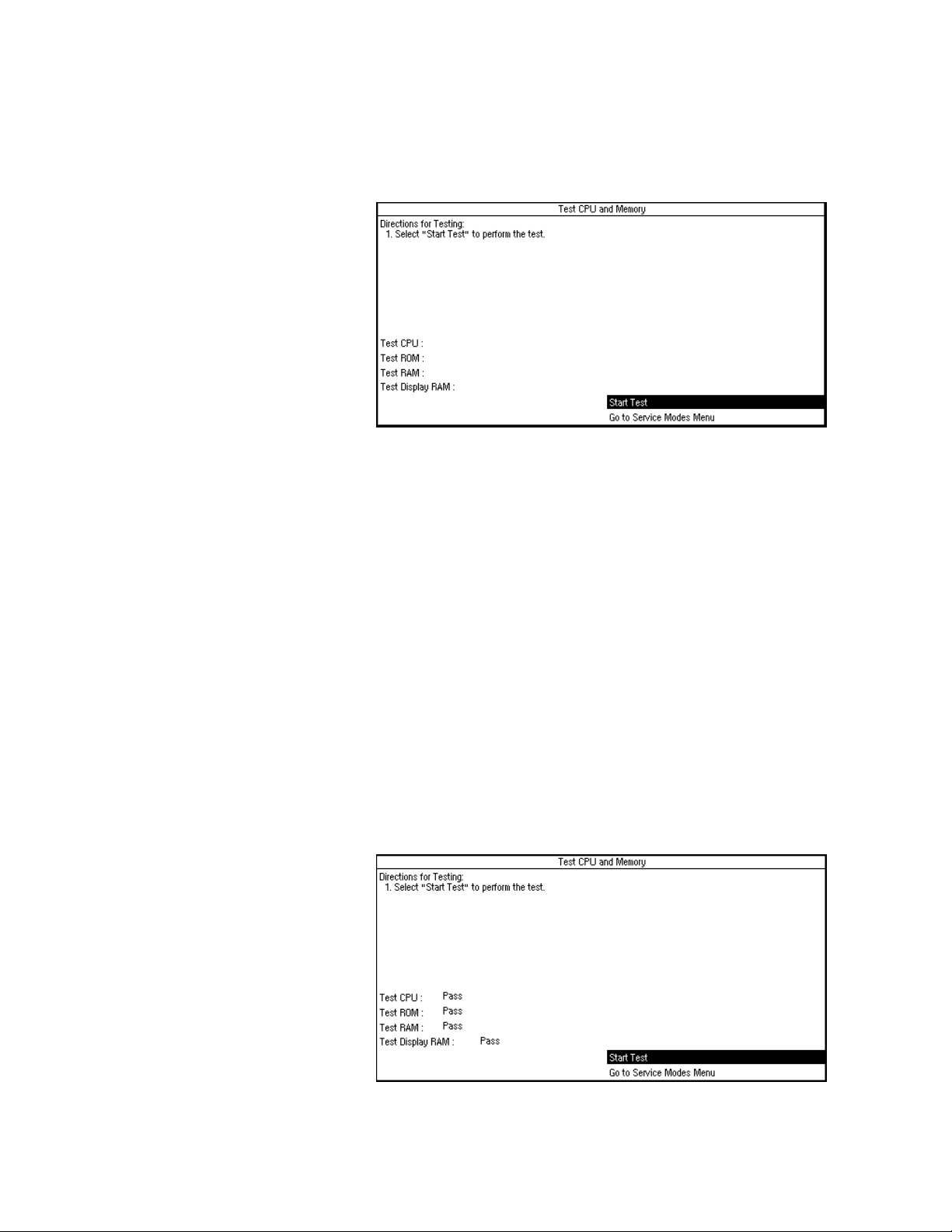
4a Tests and Calibration 4.X Software
4a.3.5 Test CPU and
Memory
Figure 4-14 • Test CPU and Memory menu
The software checks the CPU, ROM, RAM, and display RAM through this
menu. When Start Test is selected the series of tests begins to run. When each
test is running, the word “Testing. . .” appears after the test name.
First the software tests the CPU integer instruction set and the CPU register(s).
If this test fails, the CPU did not perform the integer instruction set correctly, or
the CPU register(s) have failed.
Next, the software tests the Flash ROM via a CRC check (Cyclic Redundancy
Check). A CRC value has been calculated for the Flash ROM memory and this
value is stored in the Flash ROM. This test recalculates the CRC for the Flash
ROM and compares it to the value stored in Flash ROM. If the value that was
calculated does not equal the value that was stored in Flash ROM, the test will
fail.
Finally, the software tests all the external and display RAM memory with a
walking bit pattern test. It writes a certain bit pattern to a block of memory and
then reads that block of memory. If the bit pattern what it wrote is not the
same bit pattern that it reads back, the test fails.
When the test is complete and has passed, the word “Pass” appears after the
name of the test, as in Figure 4-15.
Figure 4-15 • Test CPU and Memory menu after all the tests have passed
4a-14 05/04 1006-0453-000
Page 61

4a.3.6 Test EEPROM The software tests all the EEPROM memory via a bit pattern test. It writes a
Figure 4-16 • Test EEPROM menu
4a Tests and Calibration 4.X Software
certain pattern to a block of memory and then reads back that block of
memory. If the bit pattern that was written is not the same bit pattern that it
reads back, the test fails.
1006-0453-000 05/04 4a-15
Page 62

4a Tests and Calibration 4.X Software
4a.3.7 Test GIV To test the GIV (gas inlet valve) the software first closes the GIV. It reads the
A/D channel for the GIV. If the A/D channel for the GIV does not read closed,
the test fails; otherwise, the test continues.
The software then opens the flow valve to the calibrated flow of the bleed
resistor and waits for the flow to stabilize (about 2 seconds). Once the flow is
stabilized the software checks to see if manifold pressure has dropped to less
than 0.5 cm H
O. If manifold pressure does not drop below 0.5 cm H2O, the
2
test fails; otherwise, the test continues.
The software then closes the flow valve and opens the GIV. It reads the A/D
channel for the GIV. If the A/D channel for the GIV does not read open, the test
fails.
Figure 4-17 • Test GIV menu
GIV Test FAIL instructions Failure can be caused by the valve or the CPU board malfunctioning.
Use a multimeter to measure the resistance of the GIV solenoid. It should be
approximately 25 ohms. If necessary, replace the GIV solenoid
(see section 7).
Use a multimeter to measure the voltage at the inlet valve connector on the
pneumatic connection board. The voltage should be 4.5 volts when the GIV is
open.
• If the voltage is 4.5 volts or greater, service the GIV (see section 7).
• If the voltage is less than 4.5 volts replace the CPU board (see section 7).
4a-16 05/04 1006-0453-000
Page 63

4a Tests and Calibration 4.X Software
4a.3.8 Test Flow Valve To test the flow valve the software starts by closing the flow valve. It then
opens the flow valve in increments until the flow valve is completely open. At
each of the settings of the flow valve the A/D (Analog/Digital) channel for
Flow DAC (Digital to Analog Converter) Feedback and Flow Current Sense will
be read. If the A/D for the Flow DAC Feedback and Flow Current Sense are not
within the correct tolerance the test fails.
After setting the Bag/Vent switch to Vent, disengage the drive gas from the
breathing system by removing the bellows housing.
Figure 4-18 • Test Flow Valve menu
Flow Valve Test FAIL
instructions
A failure can be caused either by the drive circuit or a flow valve malfunction.
Go to the “Flow Valve Test Tool” menu to check the drive circuit for proper
voltage output.
Set the flow control to output 120 liters per minute. Unplug the connector
from the pneumatic connection board and measure the resistance between
the leads at the unplugged flow valve connector. A multimeter should read
approximately 1.75 ohms.
• If the resistance is approximately 1.75 ohms, the drive circuit is bad, replace
the CPU board (see section 7) and test the flow valve again.
• If the flow valve test fails again, replace the flow valve (see section 7).
1006-0453-000 05/04 4a-17
Page 64

4a Tests and Calibration 4.X Software
4a.3.9 Test Drive
Pressure Limit Switch
The software tests the pressure limit switch to make sure that it trips at the
correct manifold over pressure. The software opens the flow valve to a value
where pressure continues to increase. It then waits for the DPL (Drive Pressure
Limit) switch to trip. The pressure at which the DPL switch tripped is indicated.
This value is the manifold pressure measured upstream of the drive gas check
valve (the typical reading is 112 cm H
switch. If the DPL switch never trips (within 15 seconds) the test fails. If the
DPL switch does not trip at a pressure within the correct tolerance, the test
fails.
Figure 4-19 • Test Drive Pressure Limit Switch menu
O), not the actual pressure at the
2
Drive Pressure Limit Switch FAIL
instructions
Go to the Discrete I/O signal menu and check the DPL (Drive Pressure Limit)
switch status (Off).
Remove the rear subfloor. Connect a pressure test device to the black inline
connector that is in the Exhalation Valve interface cuff tubing (SIB side).
Apply 104 +5/-4 cm H
O (76.5 +3.8/-2.9 mm Hg) to activate the switch.
2
Verify status change on the I/O signal screen (On).
If problem continues, replace SIB.
4a-18 05/04 1006-0453-000
Page 65

4a Tests and Calibration 4.X Software
4a.3.10 Test 5V Fail
Alarm
A 5-Volt supply (VDD) is used to power the digital circuits throughout the
ventilator.
The 5-Volt supply (VDD) is derived in the power section of the control board. It
is used to power the digital circuits throughout the ventilator. If the 5-Volt
supply fails, the ventilator will sound a continuous alarm tone when the system
switch is turned on.
To test the 5V Fail Alarm, follow the directions on the screen.
If the alarm tone does not sound, replace the CPU board (see section 7).
Figure 4-20 • Test 5V Fail Alarm menu
1006-0453-000 05/04 4a-19
Page 66

4a Tests and Calibration 4.X Software
4a.3.11 Test Serial Ports Two serial port tests may be done:
• Public Port Test (Com 2) - requires pins 6 and 13 of the serial connector to
be jumpered.
• Proprietary Port Test (Com 1)- requires pins 2 and 3 of the serial connector
to be jumpered.
Com 1 and Com 2 ports are located on the back of the ventilator and are
identified with the following symbol:
Each test routine sets up the serial port circuits so transmitted data is echoed
directly back to the receive circuits. The test fails if the data sent out is not
equal to the data received.
If only the Proprietary Port Test fails, replace the CPU.
If both tests fail:
• check the harness connections between the control board and the Serial
Adaptor Board (SAB).
• check the ribbon cable between the SAB and the external connector.
• replace the SAB.
Figure 4-21 • Test Serial Ports menu
4a-20 05/04 1006-0453-000
Page 67

4a Tests and Calibration 4.X Software
4a.3.12 Breathing
System Leak Test
You can estimate how much of a leak there is in the ventilator portion of the
breathing system by closing the patient circuit, inflating the bellows, and
observing how quickly they fall on their own weight (part of the machine
checkout procedure).
The Breathing System Leak Test allows you to more precisely test the
ventilator portion of the breathing circuit for leaks.
By using the patient circuit to establish a closed loop, you can measure the
leak rate.
• The leak rate is the fresh gas flow needed to maintain 30 cmH2O.
• The system should have a leak rate <200 mL/min.
Figure 4-22 • Breathing System Leak Test menu
1006-0453-000 05/04 4a-21
Page 68

4a Tests and Calibration 4.X Software
4a.3.13 Display A/D
The software displays the A/D values for each of the A/D channels.
Channels
Figure 4-23 • Page 1 of Display A/D Channels menu
Figure 4-24 • Page 2 of Display A/D Channels menu
Remarks This selection displays a listing of A/D Channels which are at various values
depending upon the set parameters.
Refer to the following table for additional details for each of the displayed
channels.
4a-22 05/04 1006-0453-000
Page 69

Table 4a-1 A/D Channels
4a Tests and Calibration 4.X Software
A/D Channel
Inspiratory Flow
1
Counts
2
1800-2300 Near Zero L/min -120 to 120 L/min Zero Offset Reading (nominal 2050
Actual Range
1
Displayed Range Special Instructions
Counts)
Expiratory Flow
2
1800-2300 Near Zero L/min -120 to 120 L/min Zero Offset Reading (nominal 2050
Counts)
Airway Pressure
Manifold Pressure
2
550-1050
550-1050
Near Zero cm H
Near Zero cm H
O -20 to 120 cm H2O
2
O -20 to 120 cm H2O
2
Zero Offset Reading (nominal 800 Counts)
Zero Offset Reading (nominal 800 Counts)
2
O2 0-4095 0 to 100% 0 to 100% Count weight and limits are determined
during O2 calibration
Flow Current Sense 0-4095 0 to 1.024 Amp 0 to 1.024 Amps
Flow DAC Feedback 0-4095 0 to 4.095 Volts 0 to 4.095 Volts
Battery Voltage 1740-3976 7 to 16 Volts 0 to 16.48 Volts <7V = Low battery voltage failure.
<11.65V = Low battery voltage warning.
>16 Volts (10 Sec) = High battery voltage
failure.
Battery Current 700-4000 -600 mA to 6 Amps -2 to 6.19 Amps -150 to -600 mA = Battery charging.
-601 mA to -2 Amps = Charge current out of
range.
>300 mA = Operating on battery.
>6 Amps = Battery discharge current out of
range.
1.225 Voltage
1214-1235 1.214 to 1.235 Volts 0 to 4.095 Volts
Reference
5.8V Voltage Test 1997-2565 4.86 to 6.24 Volts 0 to 9.96 Volts
+15V Analog Supply 1914-2262 13.77 to 16.27 Volts 0 to 29.46 Volts
-15V Analog Supply 858-953 -12.62 to -17.46 Volts -61 to 1.43 Volts
+12V SIB Supply 1779-2322 10.44 to 13.62 Volts 0 to 24 Volts
VEL Supply 1645-2675 9.56 to 15.69 Volts 0 to 24 Volts
VSW Supply 1269-2368 9.13 to 17.04 Volts 0 to 29.46 Volts
+12V Light Supply 1879-2217 11.02 to 13 Volts 0 to 24 Volts In Rev 3.4 software,
Range = 10.00 to 12.73 Volts
3
GIV Current Sense
2371-3884 143.7 to 235.4 mA 0 to 248.2 mA Off state reading is 0 to 259 counts
Notes:
1. These columns show the acceptable range where possible.
2. The A/D count and displayed value shown for Airway Pressure, Manifold Pressure, Inspiratory Flow, and Expiratory Flow are the zero
pressure values. These readings should be taken with the flow sensors disconnected by removing the circuit module.
3. The count range and displayed value shown for GIV Current Sense is with the GIV turned on. If the GIV is turned off, the off count range
is 0 to 259 Counts.
1006-0453-000 05/04 4a-23
Page 70

4a Tests and Calibration 4.X Software
4a.3.14 Display Discrete
I/O Signals
The Discrete I/O Signals menu displays discrete binary signals associated with
machine switch positions.
There are several types of switches in the Aestiva machine:
Figure 4-25 • Display Discrete I/O Signals menu
• some switches are mechanically operated
• some switches are pneumatically operated
• some switches are electronic
Mechanical switches • ACGO Switch Status — Ventilation or Aux CGO (machines with ACGO)
•CO
Bypass — Off or On
2
• Canister Status — Closed or Open
• Control Panel Cover — Closed or Open
• Bag/Vent Status — Bag or Vent
Pneumatic switches • Pressure Limit Status — Off or On
•O
Flush Status — Off or On
2
•O
Supply Pressure Status — Pressure or No Pressure
2
Electronic switches •O
Sensor Status — Connected or Disconnected
2
• Circuit module ID:
Breathing Circuit
Switch
One Off On On
Two Off Off On
Three On Off On
Circle Bain/Mapleson D (no module)
Off = tab present to block light
On = no tab to block light
4a-24 05/04 1006-0453-000
Page 71

4a Tests and Calibration 4.X Software
4a.3.15 Display Battery
Status
The software displays the battery charge status. This checks the battery
charge current.
NNNNooootttteeee:::: A negative current value means the battery is charging.
BBBBaaaatttttttteeeerrrryyyy SSSSttttaaaattttuuuuss
On Battery Battery Current > 0.300 Amps
Battery Charging -0.600 ≤ Battery Current ≤ -0.150
Battery Charged none of the above
ss
VVVVaaaalllluuuueeeessss DDDDiiiissssppppllllaaaayyyyeeeedd
dd
Figure 4-26 • Display Battery Status menu
If the battery has been on charge for several hours and you get a “battery is
not charged” display:
• Check the battery in-line cable fuse.
• If the fuse is good, the battery is bad and you should replace it.
1006-0453-000 05/04 4a-25
Page 72

4a Tests and Calibration 4.X Software
4a.3.16 Test Panel
Switches
Remarks If any of the select buttons test fails, replace the front panel keyboard
In the Test Panel Switches menu the software is set up to receive keyboard
button presses and rotary encoder turns.
Press each button and turn the encoder one full turn in both directions.
When a button is pressed and held, the icon on the screen next to the button
will contain an “x”.
After testing all the buttons and the control knob, select “Test Encoder Knob
Tur n”.
As you turn the encoder knob, verify that:
• each click of the encoder in the clockwise direction increments the clockwise
total.
• each click of the encoder in the counterclockwise direction increments the
counterclockwise total.
assembly (see section 7). If the encoder knob test fails, replace the rotary
encoder assembly (see section 7).
Figure 4-27 • Test Panel Switches menu
4a-26 05/04 1006-0453-000
Page 73

4a Tests and Calibration 4.X Software
4a.3.17 Flow Valve Test
Tool
Figure 4-28 • Flow Valve Test Tool menu
The Flow Valve Test Tool is available for test and troubleshooting purposes
only. It allows you to manually control the flow valve setting from 0 (closed) to
120 LPM, in 1 LPM increments, and observe key pressure and flow
measurements on the same screen.
This is mainly used to test the drive gas circuit and MOPV valves as detailed in
the MOPV test procedure (see section 5.4). However, it can also be used for
other troubleshooting procedures whenever a set flow is required.
NNNNooootttteeee:::: The flow does not turn off automatically. The flow must be set to zero to
stop flow. Flow will originally be set to zero upon entering this screen.
1006-0453-000 05/04 4a-27
Page 74

4a Tests and Calibration 4.X Software
4a.3.18 Adjust Drive Gas
Regulator
Figure 4-29 • Adjust Drive Gas Regulator menu
The Adjust Drive Gas Regulator procedure establishes the required flow rate
through the drive gas regulator for proper calibration.
Remarks The drive gas regulator should provide a constant gas input pressure of
17 2 kPa (25 psi).
You can verify this pressure by attaching a pressure test device to the
regulator pressure port (shown below) and performing the above procedure.
If required, adjust the regulator to 172 ±1.72 kPa (25 ±0.25 psi).
Regulator
pressure
port
Figure 4-30 • Location of the regulator pressure port
4a-28 05/04 1006-0453-000
Page 75

4a Tests and Calibration 4.X Software
4a.3.19 O2 Calibrations The O2 Calibrations take into account the altitude setting. Before starting the
calibrations, ensure that the altitude setting (in Calibrations/System
Configuration) is set to the appropriate altitude for the machine location.
Note: a circle module is required for all calibrations.
For the 21% O2 calibration, software reads the A/D value for the O2 sensor
when the O2 sensor is exposed to room air (21% O2).
• If this A/D value is not within the tolerance, the calibration fails.
• If the calibration passes, the A/D value is stored in the EEPROM.
The sensor must be calibrated at 21% O2 before calibration at 100% O2.
Figure 4-31 • O2 Calibrations menu
Remarks Remove the O2 sensor from the breathing system and expose it to room air.
The displayed reading should be 21% ±2% to pass the calibration
requirements.
Reinstall the sensor that passed the 21% test in the breathing system and
expose it to 100% O2. Select “Start 100% O2 Calibration” to begin test.
If it displays readings higher or lower than required to pass, replace the
sensor.
1006-0453-000 05/04 4a-29
Page 76

4a Tests and Calibration 4.X Software
4a.3.20 Calibrate Flow
Sensors
Figure 4-32 • Calibrate Flow Sensors menu
The software calibrates the inspiratory flow, expiratory flow, airway pressure
and manifold pressure transducers for zero flow/pressure offset voltage. It
does so by reading the A/D values for inspiratory flow, expiratory flow, airway
pressure and manifold pressure when the flow sensor module has been
disconnected from the bulkhead connector. If the A/D values are not within
the correct tolerance, the calibration fails. If the calibration passes, the offset
A/D values at which the inspiratory flow, expiratory flow, airway pressure and
manifold pressure transducers were calibrated at, are stored in the EEPROM.
Remarks Fail - indicates a problem with the SIB.
Inspect the Bulkhead Connector and SIB tubing for moisture or possible
occlusion.
Check for bad differential pressure transducer.
• Ensure that the flow sensor module is disconnected from the bulkhead
panel.
• Check the transducer outputs using the Display A/D menu.
• If the transducer is out of tolerance (Refer to Table 4a-1, on page 4-23),
replace the SIB assembly.
4a-30 05/04 1006-0453-000
Page 77

4a Tests and Calibration 4.X Software
4a.3.21 Pressure
Sensitivity
Note This pressure transducer calibration must be per formed if the SIB assembly or
The software prompts the user to perform the procedure to calibrate the
pressure sensitivity. This calibration is not an automated calibration. It
prompts the user to follow a set of procedural steps to perform the
calibration. This calibration calculates the pressure sensitivity at four different
pressures. It uses these four different pressure points along with the
inspiratory flow and expiratory flow zero offsets to find the pressure
sensitivity. If the calculations for the pressure sensitivity are not within the
correct tolerance, the calibration fails. If the calibration passed, the four
pressure sensitivity points are stored in the EEPROM.
CPU board is replaced.
The Pressure Sensitivity Calibration can not be successfully performed using a
Bain/Mapleson D breathing circuit module. Install a Circle module to perform
the calibration.
Figure 4-33 • Pressure Sensitivity menu
Pressure sensitivity FAIL
instructions
w Caution If either sensor reads more than 2 LPM, STOP. This indicates a possible
Flow Sensor Leak Test:
1. Select “Display A/D Channels” from the Diagnostic Tests/Tools menu.
Set Fresh gas flow to 2 LPM.
Open the APL valve (0 cm H
Place Bag to Vent switch in the Bag/APL position.
Connect a short tube between the inspiratory and expiratory flow sensors.
The airway pressure, inspiratory flow and expiratory flow on the ventilator
display should read near zero (between +0.5 and -0.5 LPM flows).
2. Occlude the bag port. Adjust the APL to read 10 cm H
flow may jump briefly, but should stabilize to read between +0.5 and -0.5
LPM. Very gently push the tubes coming from the flow sensors slightly in all
directions. Observe to see if the flow measurements jump.
O).
2
O on the gauge. The
2
leak in the flow sensor pneumatic circuit. Skip steps 3 and 4, go directly
to step 5. If the pressure is increased further, the SIB may be damaged.
1006-0453-000 05/04 4a-31
Page 78

4a Tests and Calibration 4.X Software
3. Adjust the APL to read 20 cm H2O on the gauge. The flows may jump briefly,
but should stabilize to read between +0.5 and -0.5 LPM.
4a.3.22 Calibrate Flow
Valve
4. Adjust the APL to read 40 cm H
O on the gauge. The flows may jump briefly,
2
but should stabilize to read between +0.5 and -0.5 LPM.
5. If the flow measurements on the ADC page stay near zero, the flow sensors
are good. If either sensor indicates a flow where there is none, there may be
a leak. To troubleshoot, reduce the circuit pressure back to zero. Reverse
the flow sensor connections at the SIB interface panel and repeat the
above tests.
6. If the problem follows the sensor, discard the sensor. It has a leak.
7. If the problem stays with the same side of the circuit, it is likely the leak is
in the tubing, not with the sensor.
The software prompts the user to perform the procedural steps to calibrate
the flow valve. This is an automated calibration. It gradually opens the flow
valve and monitors the manifold pressure. When the manifold pressure
reaches 1.9 to 2.0 cm H
O the value at which the flow valve has been opened
2
is saved. The flow valve is then closed. The value at which the flow valve was
opened to is then checked to make sure it is within the correct tolerance. If it is
not, the calibration fails. If the calibration passes, the flow valve calibration
point is stored in the EEPROM.
Figure 4-34 • Calibrate Flow Valve menu
Remarks Check that the Bag/Vent selection switch is in the vent position. If the flow
valve calibration test fails immediately, the most likely fault is a failed
manifold transducer. It can also be a failed regulator or the regulator could
need calibration. Another cause could be a failed flow valve.
4a-32 05/04 1006-0453-000
Page 79

4a Tests and Calibration 4.X Software
4a.3.23 Bleed Resistor
Calibration
Figure 4-35 • Bleed Resistor Calibration menu
Software procedure The software performs the calibration as follows:
The software calibrates the bleed resistor as described below. Other than the
setup procedure, this calibration is completely automated.
1. Opens the flow valve to the starting point that was found (where
manifold pressure is 91-92 cm H2O).
2. Waits for the flow to stabilize.
3. Once the flow stabilized, sets the flow to 12 L/min.
4. Wait for the flow to stabilize.
5. Repeat steps 1-4, replacing step 3 with progressively smaller flows.
There are 12 points that are calculated for the bleed resistor calibration. If the
calibration passes, the calculated bleed resistor calibration points are stored
in EEPROM.
Remarks If the bleed resistor calibration test fails, check altitude and drive gas settings.
Ensure that the breathing circuit gas is exhausting out the scavenging port
during the test. A negative finding indicates a massive circuit leak. Check for
proper regulator pressure calibration. Ensure that the Flow Valve Cal test was
conducted properly. Otherwise, failure indicates a calibration problem with
the flow valve.
1006-0453-000 05/04 4a-33
Page 80

4a Tests and Calibration 4.X Software
4a.3.24 Service
Calibrations Required
Figure 4-36 • Service Calibrations Required menu
The Schedule Service Calibrations menu lists which setting or calibration
must be performed when the “Service Calibration
normal operation. After the setting or calibration is properly completed, the
text for that setting or calibration is removed from the list.
The normal operation “Service Calibration w” alarm message is only removed
when all the required settings or calibrations are completed.
w” alarm appears in
Remarks The Set Service Calibration menu item is used by the factory to activate the
Figure 4-37 • Set Service Calibration menu
Service Calibration alarm and require that all settings and calibrations be
performed when the Aestiva machine is set up for operation at its permanent
location.
There is no need to set the “Service Calibration
Select “No” when the following warning appears if you selected the
“Set Service Cal” menu item.
If you select “Yes” you will see the screen displayed in Figure 4-38. Follow the
directions on the screen to complete the calibrations.
w” alarm in the field.
4a-34 05/04 1006-0453-000
Page 81

Figure 4-38 • Service Calibration full menu
4a Tests and Calibration 4.X Software
1006-0453-000 05/04 4a-35
Page 82

Notes
4a-36 05/04 1006-0453-000
Page 83

4b Tests and Calibration — Software Revisions
1.X and 3.X
wwwwWARNING Post-Service Checkout is required after you complete this section. You must
perform
Section 3.1 Post-service checkout
after performing any maintenance,
service or repair. Failure to do so may result in patient injury.
w CAUTION Section 4b should only be used with versions 1.X and 3.X software. Tests and
Calibrations for version 4.X software are located in section 4a.
In this section
1006-0453-000 05/04 4b-1
To ensure proper operation, the Aestiva 7900 Ventilator includes several tests that run
automatically (self tests) and a series of menu pages that a qualified service person can
use to test, calibrate, or troubleshoot ventilator related components in the Aestiva
machine (Service Mode).
4b.1 Self tests . . . . . . . . . . . . . . . . . . . . . . . . . . . . . . . . . . . . . . . . . . . . . . . . . . . . . . . . . . . . . . 4b-3
4b.2 Service Mode Confirmation menu . . . . . . . . . . . . . . . . . . . . . . . . . . . . . . . . . . . . . . . . . . 4b-4
4b.2.1 Set the altitude . . . . . . . . . . . . . . . . . . . . . . . . . . . . . . . . . . . . . . . . . . . . . . . . . . . 4b-5
4b.2.2 Set the language . . . . . . . . . . . . . . . . . . . . . . . . . . . . . . . . . . . . . . . . . . . . . . . . . 4b-5
4b.2.3 Set the serial connection . . . . . . . . . . . . . . . . . . . . . . . . . . . . . . . . . . . . . . . . . . . 4b-5
4b.3 Main Menu - Service Calibration Mode . . . . . . . . . . . . . . . . . . . . . . . . . . . . . . . . . . . . . . 4b-6
Page 84

4b.4 Diagnostic Tests . . . . . . . . . . . . . . . . . . . . . . . . . . . . . . . . . . . . . . . . . . . . . . . . . . . . . . . . 4b-7
4b.4.1 Test CPU . . . . . . . . . . . . . . . . . . . . . . . . . . . . . . . . . . . . . . . . . . . . . . . . . . . . . . . . 4b-7
4b.4.2 Test External RAM . . . . . . . . . . . . . . . . . . . . . . . . . . . . . . . . . . . . . . . . . . . . . . . . . 4b-7
4b.4.3 Test Display RAM . . . . . . . . . . . . . . . . . . . . . . . . . . . . . . . . . . . . . . . . . . . . . . . . . 4b-8
4b.4.4 Test Flash ROM . . . . . . . . . . . . . . . . . . . . . . . . . . . . . . . . . . . . . . . . . . . . . . . . . . . 4b-8
4b.4.5 Test EEPROM . . . . . . . . . . . . . . . . . . . . . . . . . . . . . . . . . . . . . . . . . . . . . . . . . . . . 4b-9
4b.4.6 Test Panel Switches . . . . . . . . . . . . . . . . . . . . . . . . . . . . . . . . . . . . . . . . . . . . . . . 4b-9
4b.4.7 Test Serial Ports . . . . . . . . . . . . . . . . . . . . . . . . . . . . . . . . . . . . . . . . . . . . . . . . . 4b-10
4b.4.8 Test Flow Valve . . . . . . . . . . . . . . . . . . . . . . . . . . . . . . . . . . . . . . . . . . . . . . . . . . 4b-11
4b.4.9 Test GIV (Gas Inlet Valve) . . . . . . . . . . . . . . . . . . . . . . . . . . . . . . . . . . . . . . . . . . 4b-12
4b.4.10 Test DPL (Drive Pressure Limit) switch . . . . . . . . . . . . . . . . . . . . . . . . . . . . . . 4b-13
4b.4.11 Test 5V Fail Alarm . . . . . . . . . . . . . . . . . . . . . . . . . . . . . . . . . . . . . . . . . . . . . . . 4b-14
4b.5 Diagnostic Tools . . . . . . . . . . . . . . . . . . . . . . . . . . . . . . . . . . . . . . . . . . . . . . . . . . . . . . . 4b-15
4b.5.1 Display A/D channels . . . . . . . . . . . . . . . . . . . . . . . . . . . . . . . . . . . . . . . . . . . . 4b-15
4b.5.2 Display I/O signals . . . . . . . . . . . . . . . . . . . . . . . . . . . . . . . . . . . . . . . . . . . . . . . 4b-17
4b.5.3 Battery Charge Status . . . . . . . . . . . . . . . . . . . . . . . . . . . . . . . . . . . . . . . . . . . . 4b-18
4b.5.4 System Error Log . . . . . . . . . . . . . . . . . . . . . . . . . . . . . . . . . . . . . . . . . . . . . . . . . 4b-19
4b.5.5 Alarm log . . . . . . . . . . . . . . . . . . . . . . . . . . . . . . . . . . . . . . . . . . . . . . . . . . . . . . . 4b-19
4b.6 Flow Valve Test Tool . . . . . . . . . . . . . . . . . . . . . . . . . . . . . . . . . . . . . . . . . . . . . . . . . . . . 4b-20
4b.7 Test Breathing System For Leak . . . . . . . . . . . . . . . . . . . . . . . . . . . . . . . . . . . . . . . . . . . 4b-21
4b.8 Adjust Drive Gas Regulator . . . . . . . . . . . . . . . . . . . . . . . . . . . . . . . . . . . . . . . . . . . . . . . 4b-22
4b.9 Calibrations . . . . . . . . . . . . . . . . . . . . . . . . . . . . . . . . . . . . . . . . . . . . . . . . . . . . . . . . . . . 4b-23
4b.9.1 Calibrate O2 Sensor . . . . . . . . . . . . . . . . . . . . . . . . . . . . . . . . . . . . . . . . . . . . . . 4b-23
4b.9.2 Calibrate Flow Sensors . . . . . . . . . . . . . . . . . . . . . . . . . . . . . . . . . . . . . . . . . . . 4b-24
4b.9.3 Pressure Sensitivity Calibration . . . . . . . . . . . . . . . . . . . . . . . . . . . . . . . . . . . . . 4b-25
4b.9.4 Calibrate Flow Valve . . . . . . . . . . . . . . . . . . . . . . . . . . . . . . . . . . . . . . . . . . . . . . 4b-26
4b.9.5 Calibrate Bleed Resistor . . . . . . . . . . . . . . . . . . . . . . . . . . . . . . . . . . . . . . . . . . 4b-27
4b.10 Schedule Service Calibration — Software 3.X . . . . . . . . . . . . . . . . . . . . . . . . . . . . . . . 4b-28
4b.11 Sensor(s) cal due — Software 1.X . . . . . . . . . . . . . . . . . . . . . . . . . . . . . . . . . . . . . . . . 4b-29
4b.12 User Settings . . . . . . . . . . . . . . . . . . . . . . . . . . . . . . . . . . . . . . . . . . . . . . . . . . . . . . . . . 4b-30
4b.12.1 Select Altitude . . . . . . . . . . . . . . . . . . . . . . . . . . . . . . . . . . . . . . . . . . . . . . . . . 4b-30
4b.12.2 Select Drive Gas . . . . . . . . . . . . . . . . . . . . . . . . . . . . . . . . . . . . . . . . . . . . . . . . 4b-30
4b.12.3 Adjust Brightness . . . . . . . . . . . . . . . . . . . . . . . . . . . . . . . . . . . . . . . . . . . . . . . 4b-31
4b.12.4 Select Heliox Mode . . . . . . . . . . . . . . . . . . . . . . . . . . . . . . . . . . . . . . . . . . . . . 4b-31
4b.12.5 VE Alarm Limits . . . . . . . . . . . . . . . . . . . . . . . . . . . . . . . . . . . . . . . . . . . . . . . . 4b-32
4b.12.6 User Select Defaults . . . . . . . . . . . . . . . . . . . . . . . . . . . . . . . . . . . . . . . . . . . . 4b-32
4b-2 05/04 1006-0453-000
Page 85

4b Tests and Calibration 1.X/3.X Software
4b.1 Self tests The Aestiva 7900 Ventilator software includes self tests that determine
whether or not the operating software is functioning properly and whether or
not the electronic circuits on the circuit boards are functional.
The self tests include:
• Powerup tests
• Continuous tests
• Periodic tests
Powerup tests The following is a list of the tests run at powerup:
• Sequential watchdog
• Logical watchdog
• Data RAM walking pattern test
• FLASH ROM CRC verification
• Gas inlet valve test (electrical and pneumatic)
• Calibration of the manifold sensor
If one or more of these tests fail, the display provides a readout of the
problem.
The On and Off states of the Gas Inlet Valve (GIV) are tested at power up. The
electronic feedback signal as well as the manifold pressure will be tested to
determine pass/failure. If the GIV causes the self test to fail on power up, an
alarm sound and the message “Gas Inlet Valve Failure” is displayed. An error
code (1002C) will register on the error code service mode menu.
If the calibration of the manifold sensor fails on power up, an alarm sounds
and the message “Manifold Pressure Sensor Failure” is shown. An error code
(1003E) will also show on the error code service menu.
Continuous tests These tests are run continuously during normal operation and alarms are
associated with each test. A failure causes an alarm to display on the screen
in the alarm display area.
• Flow valve electrical feedback
• Gas inlet valve electrical feedback
• Supply voltage checks
• Battery voltage checks
The flow valve feedback signal is tested in non-mechanical and mechanical
ventilation states. The flow valve is closed in non-mechanical ventilation.
The Gas Inlet Valve ON state is tested (via electronic feedback) every 3
seconds once normal operation is entered.
Periodic tests These tests are run every 30 seconds during normal operation. Alarms are
associated with each test. A failure causes an alarm to display on the screen
in the alarm display area.
• CPU Test
• Display RAM walking pattern test
• Data RAM walking pattern test
• FLASH ROM CRC verification
1006-0453-000 05/04 4b-3
Page 86

4b Tests and Calibration 1.X/3.X Software
4b.2 Service Mode Confirmation menu
The service calibration mode tests and/or calibrates hardware necessary to
prepare a ventilator in manufacture for factory shipment and to service a
ventilator in the field.
There are two ways to enter the service mode:
• If the machine is turned off, push and hold in the adjustment knob while
setting the system switch to On. Hold the adjustment knob pushed in
until the “Service Mode Confirmation” menu appears. Use the
adjustment knob to highlight “Service Mode”, then push the adjustment
knob to confirm the selection.
• If the machine is already in normal operation, set the Bag/Vent switch to
Bag. Then, press the V
same time to reset the software (powerup). Push and hold the
adjustment knob until the “Service Mode Confirmation” menu appears.
All data displayed by the ventilator during and after a service mode test or
measurement is also output to the serial port.
/Pinsp, the PEEP, and the menu switches at the
T
Figure 4b-1 • Service confirmation menu
From this menu you can:
• Set Altitude
• Set Language
• Set Serial Connection
• Go to the Service Mode or Normal Operation
4b-4 05/04 1006-0453-000
Page 87

4b Tests and Calibration 1.X/3.X Software
4b.2.1 Set the altitude The accuracy of some of the ventilator measurements is altitude sensitive. To
ensure the specified accuracy, the altitude setting should be set to the specific
altitude where each machine is located.
Altitude setting ranges from -400 to 3600 meters in increments of 100
meters. The setting is saved in EEPROM and the default value is 300 meters.
4b.2.2 Set the language Text shown in the normal mode of operation is language sensitive, but the
service confirmation and calibration modes are shown in English. The other
language choices are shown in language specific text. For example, Swedish
would be shown as “Svenska”.
The language choices are:
• English
• French
• German
• Italian
• Spanish
• Japanese
• Dutch
• Swedish
4b.2.3 Set the serial
connection
The language setting is stored in EEPROM with the default setting as English.
There are two serial ports on the Aestiva 7900 Ventilator, the Datex-Ohmeda
proprietary channel and the public channel. The proprietary channel is used
for software development testing and manufacturing test.
The public channel serial connection alternatives are:
• Ohmeda RGM
• 7800 Emulation
• Ohmeda Com 1.0
• Ohmeda Com 2.0
The serial connection used is stored in EEPROM. The default selection is
Ohmeda RGM.
When you are in the serial connection menu, all display graphics except for
the menu box are removed from the screen. All switches other than the
adjustment knob are inactive, therefore accidently pushing a key will not
cause any action.
1006-0453-000 05/04 4b-5
Page 88

4b Tests and Calibration 1.X/3.X Software
4b.3 Main Menu - Service Calibration Mode
The service mode is set from the service confirmation menu. Select “Service
Mode” and push the adjustment knob. The service mode Main Menu displays
all selectable service tests.
Software revision 3.X adds several menu items to the service mode. Most of
the service screens are identical in 3.X or 1.X software. Screens that differ
significantly are shown separately. Minor differences are noted in the text.
Software 3.X
Software 1.X
Figure 4b-2 • Service mode main menu
Exit Service Mode Provides the means to exit the service mode via a hardware reset.
The service mode has a top level main menu screen which displays all the
selectable service tests in categorical order; Diagnostic Tests/ Tools,
Calibrations and User settings. Any service test can be selected from this
menu with the adjustment knob cursor. The software version is shown at the
top-left of the screen and the date code is shown at the top-right of the
screen.
Allows the service person to return to the main operating waveform display
and operating menu.
4b-6 05/04 1006-0453-000
Page 89

4b.4 Diagnostic Tests
4b.4.1 Test CPU The software tests the CPU integer instructions as well as the CPU register(s).
4b Tests and Calibration 1.X/3.X Software
If this test fails, the CPU did not perform an integer instruction correctly, or the
CPU register(s) have failed.
CPU test FAIL instructions Upon FAIL, replace the CPU board (see Section 7.5).
4b.4.2 Test External RAM The software tests all of the external RAM memory with a walking bit pattern
test. It writes a certain bit pattern to a block of memory and then reads that
block of memory. If the bit pattern that it wrote is not the same bit pattern that
it reads back the test fails.
External RAM test FAIL
instructions
Upon FAIL, replace the CPU board (see Section 7.5).
1006-0453-000 05/04 4b-7
Page 90

4b Tests and Calibration 1.X/3.X Software
4b.4.3 Test Display RAM The software tests all of the display RAM memory via a walking bit pattern
test. It writes a certain bit pattern to a block of memory and then reads that
block of memory. If the bit pattern that was written is not the same bit pattern
that it reads back the test fails.
Display RAM test FAIL
Upon FAIL, replace the CPU board (see Section 7.5).
instructions
4b.4.4 Test Flash ROM The software tests the Flash ROM via a CRC check (Cyclic Redundancy Check).
A CRC value has been calculated for the Flash ROM memory and this value is
stored in the Flash ROM. This test recalculates the CRC for the Flash ROM and
compares it to the value stored in Flash ROM. If the value that was calculated
does not equal the value that was stored in Flash ROM, the test will fail.
Flash ROM test FAIL
Upon FAIL, replace the CPU board (see Section 7.5).
instructions
4b-8 05/04 1006-0453-000
Page 91

4b Tests and Calibration 1.X/3.X Software
4b.4.5 Test EEPROM The software tests all of the EEPROM memory via a bit pattern test. It writes a
certain pattern to a block of memory and then reads that block of memory. If
the bit pattern that was written is not the same as the bit pattern read back,
the test fails.
EEPROM test FAIL instructions Upon FAIL, replace the CPU board (see section 7.5).
4b.4.6 Test Panel
Switches
The software sets up the ventilator to receive all button presses and control
wheel turns. The test asks the user to press each of the buttons and turn the
control wheel one full turn in both directions. Each time a button is pressed
the number next to the button is reverse-highlighted. If the button is pressed
and the number next to the button does not reverse highlight the test for that
button failed. If all of the buttons are pressed and all of the numbers next to
the buttons are reverse-highlighted the button press test passes. The control
wheel turn test works the same way. The user is prompted to turn the control
wheel clockwise and counter-clockwise one full turn (16 clicks). When the
control wheel is turned (one full turn in either direction) and the control wheel
is working, the test passes. If the control wheel is not working, the test timesout in about 10 seconds and the test fails.
Panel switch test FAIL
instructions
1006-0453-000 05/04 4b-9
If any of the select buttons or the adjustment knob turn test fails, replace the
front panel keyboard (see Section 7.2) or the rotary encoder (see Section 7.3).
Page 92

4b Tests and Calibration 1.X/3.X Software
4b.4.7 Test Serial Ports The software performs an internal test on both of the serial ports. The
software sets up the serial ports so data sent out the serial ports is echoed
directly back to that serial port. The test fails if the data sent out is not equal to
the data received. The status of the test is displayed on the ventilator’s front
screen. The software checks the serial ports to ensure any data sent out is
looped back as a direct echo. If the returned data is not the same as that sent,
the ports test fails.
Serial port test FAIL
instructions
Upon FAIL, replace the CPU board (see Section 7.5).
4b-10 05/04 1006-0453-000
Page 93

4b Tests and Calibration 1.X/3.X Software
4b.4.8 Test Flow Valve To test the flow valve the software starts by closing the flow valve. It then
opens the flow valve in increments until the flow valve is completely open. At
each of the settings of the flow valve the A/D (Analog/Digital) channel for
Flow DAC (Digital to Analog Converter) Feedback and Flow Current Sense will
be read. If the A/D for the Flow DAC Feedback and Flow Current Sense are not
within the correct tolerance the test fails.
Software 3.X
Software 1.X
After setting the Bag/Vent switch to Vent, disengage the drive gas from the
breathing system by removing the bellows housing.
Flow valve test FAIL instructions A failure can be caused either by the drive circuit or a flow valve malfunction.
Go to the “Flow Valve Test Tool” menu (see section 4b.6) to check the drive
circuit for proper voltage output.
Set the flow control to output 120 liters per minute. Unplug the connector
from the pneumatic connection board and measure the resistance between
the leads at the unplugged flow valve connector. A multimeter should read
approximately 1.75 ohms.
• If the resistance is approximately 1.75 ohms, the drive circuit is bad, replace
the CPU board (see Section 7.5) and test the flow valve again.
• If the flow valve test fails again, replace the flow valve (see Section 7.8).
1006-0453-000 05/04 4b-11
Page 94

4b Tests and Calibration 1.X/3.X Software
4b.4.9 Test GIV
(Gas Inlet Valve)
To test the gas inlet valve the software first closes the GIV. It reads the A/D
channel for the GIV. If the A/D channel for the GIV does not read closed, the
test fails; otherwise, the test continues.
The software then opens the flow valve to the calibrated flow of the bleed
resistor and waits for the flow to stabilize (about 2 seconds). Once the flow is
stabilized the software checks to see if manifold pressure has dropped to less
than 0.5 cm H
test fails; otherwise, the test continues.
The software then closes the flow valve and opens the GIV. It reads the A/D
channel for the GIV. If the A/D channel for the GIV does not read open, the test
fails.
O. If manifold pressure does not drop below 0.5 cm H2O, the
2
GIV test FAIL instructions Failure can be caused by the valve malfunctioning or the CPU board.
Use a multimeter to measure the resistance of the GIV solenoid. It should be
approximately 25 ohms. If necessary, replace the GIV solenoid (see Section
7.9).
Use a multimeter to measure the voltage at the inlet valve connector on the
pneumatic connection board. The voltage should be 4.5 volts when the GIV is
open.
• If the voltage is 4.5 volts or greater, service the GIV (see Section 7.9).
• If the voltage is less than 4.5 volts replace the CPU board (see Section 7.5).
4b-12 05/04 1006-0453-000
Page 95

4b Tests and Calibration 1.X/3.X Software
4b.4.10 Test DPL
(Drive Pressure Limit)
switch
The software tests the pressure limit switch to make sure that it trips at the
correct manifold over pressure. The software opens the flow valve to a value
where pressure continues to increase. It then waits for the DPL (Drive Pressure
Limit) switch to trip. The pressure at which the DPL switch tripped is indicated.
This value is the manifold pressure measured upstream of the drive gas check
valve (the typical reading is 112 cm H
switch. If the DPL switch never trips (within 15 seconds) the test fails. If the
DPL switch does not trip at a pressure within the correct tolerance, the test
fails.
O), not the actual pressure at the
2
Pressure limit switch FAIL
instructions
Go to the Discrete I/O signal menu and check the DPL (Drive Pressure Limit)
switch status (Off).
Remove the rear subfloor. Connect a pressure test device to the black inline
connector that is in the Exhalation Valve interface cuff tubing (SIB side).
Apply 104 +5/-4 cm H
Verify status change on the I/O signal screen (On).
If problem continues, replace SIB.
O (76.5 +3.8/-2.9 mm Hg) to activate the switch.
2
1006-0453-000 05/04 4b-13
Page 96

4b Tests and Calibration 1.X/3.X Software
4b.4.11 Test 5V Fail
Alarm
Software 3.X
This test is only available in 3.x software.
A 5-Volt supply (VDD) is used to power the digital circuits throughout the
ventilator.
Where the 5-Volt supply (VDD) is derived depends on the type of CPU board
that is used:
• In machines with the original CPU board (non-integrated), the VDD voltage is
derived on the power supply board.
• In machines with an integrated CPU board, the VDD voltage is derived in the
power section of the CPU board.
If the VDD supply fails, the ventilator will sound a continuous alarm tone when
the system switch is turned on. The alarm is generated on the CPU board
through a dedicated “sound source” that is part of the CPU board.
To test the 5V Fail Alarm, follow the directions on the screen.
Remarks
If the alarm tone does not sound, replace the CPU board (see Section 7.5).
4b-14 05/04 1006-0453-000
Page 97

4b.5 Diagnostic Tools
4b Tests and Calibration 1.X/3.X Software
4b.5.1 Display
A/D channels
The software displays the A/D values for each of the A/D channels.
Remarks This selection displays a listing of A/D Channels which are at various values
depending upon the set parameters.
Refer to the following table for additional details for each of the displayed
channels.
1006-0453-000 05/04 4b-15
Page 98

4b Tests and Calibration 1.X/3.X Software
Table 4b-1 A/D Channels
A/D Channel
Airway Pressure
2
Manifold Pressure
Inspiratory Flow
2
1
2
Counts
550-1050
550-1050
Actual Range
Near Zero cm H
Near Zero cm H
1800-2300 Near Zero L/min -120 to 120 L/min Zero Offset Reading (nominal 2050
1
Displayed Range Special Instructions
O -20 to 120 cm H2O
2
O -20 to 120 cm H2O
2
Zero Offset Reading (nominal 800 Counts)
Zero Offset Reading (nominal 800 Counts)
Counts)
Expiratory Flow
2
1800-2300 Near Zero L/min -120 to 120 L/min Zero Offset Reading (nominal 2050
Counts)
Flow Current Sense 0-4095 0 to 1.024 Amp 0 to 1.024 Amps
Flow DAC Feedback 0-4095 0 to 4.095 Volts 0 to 4.095 Volts
3
GIV Current Sense
2371-3884 143.7 to 235.4 mA 0 to 248.2 mA Off state reading is 0 to 259 counts
O2 Concentration 0-4095 0 to 100% 0 to 100% Count weight and limits are determined
during O2 calibration
1.225 Voltage
1214-1235 1.214 to 1.235 Volts 0 to 4.095 Volts
Reference
5.8V Voltage Test 1997-2565 4.86 to 6.24 Volts 0 to 9.96 Volts
+15V Analog Supply 1914-2262 13.77 to 16.27 Volts 0 to 29.46 Volts
-15V Analog Supply 858-953 -12.62 to -17.46 Volts -61 to 1.43 Volts
+12V SIB Supply 1779-2322 10.44 to 13.62 Volts 0 to 24 Volts
VEL Supply 1645-2675 9.56 to 15.69 Volts 0 to 24 Volts
VSW Supply 1269-2368 9.13 to 17.04 Volts 0 to 29.46 Volts
+12V Light Supply 1879-2217 11.02 to 13 Volts 0 to 24 Volts In Rev 3.4 software,
Range = 10.00 to 12.73 Volts
Battery Voltage 1740-3976 7 to 16 Volts 0 to 16.48 Volts <7V = Low battery voltage failure.
<11.65V = Low battery voltage warning.
>16 Volts (10 Sec) = High battery voltage
failure.
Battery Current 700-4000 -600 mA to 6 Amps -2 to 6.19 Amps -150 to -600 mA = Battery charging.
-601 mA to -2 Amps = Charge current out of
range.
>300 mA = Operating on battery.
>6 Amps = Battery discharge current out of
range.
Notes:
1. These columns show the acceptable range where possible.
2. The A/D count and displayed value shown for Airway Pressure, Manifold Pressure, Inspiratory Flow, and Expiratory Flow are the zero
pressure values. These readings should be taken with the flow sensors disconnected by removing the circuit module.
3. The count range and displayed value shown for GIV Current Sense is with the GIV turned on. If the GIV is turned off, the off count range
is 0 to 259 Counts.
4b-16 05/04 1006-0453-000
Page 99

4b Tests and Calibration 1.X/3.X Software
4b.5.2 Display I/O
signals
The Discrete I/O Signals menu displays discrete binary signals associated with
machine switch positions.
There are several types of switches in the Aestiva machine:
• some switches are mechanically operated,
• some switches are pneumatically operated,
• some switches are electronic,
Mechanical switches • Control Panel Cover — Closed or Open
•CO
Bypass — Off or On
2
• ACGO Switch Status — Ventilation or Aux CGO (machines with ACGO)
• Bag/Vent Status — Bag or Vent
• Canister Status — Closed or Open
Pneumatic switches •O
•O
• DPL Switch Status — Off or On
Electronic switches •O
• Circuit module ID
Off = tab present to block light
On = no tab to block light
Supply Pressure Status — Pressure or No Pressure
2
Flush Status — Off or On
2
Sensor Status — Connected or Disconnected
2
Breathing Circuit
Switch
One Off On On
Two Off Off On
Three On Off On
Four On On On
Circle Bain/Mapleson D (no module)
1006-0453-000 05/04 4b-17
Page 100

4b Tests and Calibration 1.X/3.X Software
4b.5.3 Battery Charge
Status
Remarks If the battery has been on charge for several hours and you get a “battery is
The software displays the battery charge status. This checks to see if the
battery charge is greater than or equal to 12.5 volts. If it is less than 12.5
volts, the battery charge status displays that the battery is not charged. If it is
greater than or equal to 12.5 volts, the battery charge status displays that the
battery is charged.
Battery Charge Status: Battery Charged (greater than 12.5 volts)
not charged” display:
• Check the battery in-line cable fuse.
• If the fuse is good, the battery is bad and you should replace it.
4b-18 05/04 1006-0453-000
 Loading...