

Page 1
Aespire 7900
User’s Reference Manual—Part 2
Setup, Cleaning and Sterilization, Maintenance and Troubleshooting
Page 2

User Responsibility
This Product will perform in conformity with the description thereof contained
in this User’s Reference manual and accompanying labels and/or inserts,
when assembled, operated, maintained, and repaired in accordance with the
instructions provided. This Product must be checked periodically. A defective
Product should not be used. Parts that are broken, missing, plainly worn,
distorted, or contaminated should be replaced immediately. Should repair
or replacement become necessary, Datex-Ohmeda recommends that a
telephonic or written request for service advice be made to the nearest
Datex-Ohmeda Customer Service Center. This Product or any of its parts
should not be repaired other than in accordance with written instructions
provided by Datex-Ohmeda and by Datex-Ohmeda trained personnel.
The Product must not be altered without the prior written approval of
Datex-Ohmeda. The user of this Product shall have the sole responsibility
for any malfunction which results from improper use, faulty maintenance,
improper repair, damage, or alteration by anyone other than Datex-Ohmeda.
w CAUTION U.S. Federal law restricts this device to sale by or on the order of
a licensed medical practitioner. Outside the U.S.A., check local
laws for any restriction that may apply.
Datex-Ohmeda products have unit serial numbers with coded logic which
indicates a product group code, the year of manufacture, and a sequential
unit number for identification.
AAA F 12345
This alpha character indicates the year of product
manufacture and when the serial number was
assigned; “D” = 2000, “E” = 2001, “F” = 2002, etc.
“I” and “O” are not used.
S/5 Aespire, Link-25, Disposable Multi Absorber, Reusable Multi
Absorber, SmartVent, Tec 6 Plus, and Tec 7 are registered trademarks of
Datex-Ohmeda Inc.
Other brand names or product names used in this manual are trademarks or
registered trademarks of their respective holders.
Page 3

Table of Contents
Symbols used in the manual or on the equipment . . . . . . . . . . . . . . . . . . . . . . v
1 Setup and Connections
Canister setup . . . . . . . . . . . . . . . . . . . . . . . . . . . . . . . . . . . . . . . . . . . . . . . . . 1-3
When to change the absorbent . . . . . . . . . . . . . . . . . . . . . . . . . . . . . . . 1-4
Removing a canister . . . . . . . . . . . . . . . . . . . . . . . . . . . . . . . . . . . . . . . . 1-5
Reusable Multi Absorber canister filling . . . . . . . . . . . . . . . . . . . . . . . . 1-6
Pneumatic and electrical connections . . . . . . . . . . . . . . . . . . . . . . . . . . . . . 1-7
How to install gas cylinders (high pressure leak test) . . . . . . . . . . . . . . . . . . 1-8
2 Cleaning and Sterilization
Pin indexed cylinder yokes . . . . . . . . . . . . . . . . . . . . . . . . . . . . . . . . . . . 1-8
DIN cylinder connections . . . . . . . . . . . . . . . . . . . . . . . . . . . . . . . . . . .1-10
Installation notes . . . . . . . . . . . . . . . . . . . . . . . . . . . . . . . . . . . . . . . . . . . . . . 1-11
How to attach equipment to the top shelf . . . . . . . . . . . . . . . . . . . . . . . . . .1-12
Breathing system cleanable parts . . . . . . . . . . . . . . . . . . . . . . . . . . . . . . . . . 2-3
Special requirements . . . . . . . . . . . . . . . . . . . . . . . . . . . . . . . . . . . . . . . . . . . 2-4
How to clean and disinfect the flow sensors . . . . . . . . . . . . . . . . . . . . . . . . . 2-4
CIDEX sterilization . . . . . . . . . . . . . . . . . . . . . . . . . . . . . . . . . . . . . . . . . . 2-4
Procedure . . . . . . . . . . . . . . . . . . . . . . . . . . . . . . . . . . . . . . . . . . . . . . . . . 2-5
Remove the breathing system bag hose . . . . . . . . . . . . . . . . . . . . . . . . . . . . 2-6
Remove the breathing system . . . . . . . . . . . . . . . . . . . . . . . . . . . . . . . . . . . . 2-7
Disassemble the breathing system . . . . . . . . . . . . . . . . . . . . . . . . . . . . . . . . 2-8
Disassemble the Bellows assembly . . . . . . . . . . . . . . . . . . . . . . . . . . . . . . . 2-12
Assemble the Bellows assembly . . . . . . . . . . . . . . . . . . . . . . . . . . . . . . . . . 2-14
Bellows assembly tests . . . . . . . . . . . . . . . . . . . . . . . . . . . . . . . . . . . . . . . . . 2-15
1009-0633-000
Assemble the breathing system . . . . . . . . . . . . . . . . . . . . . . . . . . . . . . . . . .2-18
Install the breathing system . . . . . . . . . . . . . . . . . . . . . . . . . . . . . . . . . . . . .2-22
Remove the AGSS receiver . . . . . . . . . . . . . . . . . . . . . . . . . . . . . . . . . . . . . .2-23
Remove the AGSS receiver filter . . . . . . . . . . . . . . . . . . . . . . . . . . . . . . . . . . 2-24
Absorber canister . . . . . . . . . . . . . . . . . . . . . . . . . . . . . . . . . . . . . . . . . . . . .2-25
i
Page 4

S/5 Aespire
3 User Maintenance
Mechanical cleaning in washer or washer-disinfector . . . . . . . . . . . . 2-26
Manual cleaning . . . . . . . . . . . . . . . . . . . . . . . . . . . . . . . . . . . . . . . . . .2-26
High level disinfection . . . . . . . . . . . . . . . . . . . . . . . . . . . . . . . . . . . . . .2-26
Repair policy . . . . . . . . . . . . . . . . . . . . . . . . . . . . . . . . . . . . . . . . . . . . . . . . . . 3-2
Maintenance summary and schedule . . . . . . . . . . . . . . . . . . . . . . . . . . . . . . 3-2
User maintenance . . . . . . . . . . . . . . . . . . . . . . . . . . . . . . . . . . . . . . . . . . 3-2
Datex-Ohmeda approved
service . . . . . . . . . . . . . . . . . . . . . . . . . . . . . . . . . . . . . . . . . . . . . . . . . . . 3-3
Breathing system maintenance . . . . . . . . . . . . . . . . . . . . . . . . . . . . . . . . . . . 3-4
O
sensor replacement . . . . . . . . . . . . . . . . . . . . . . . . . . . . . . . . . . . . . . . . . . 3-4
2
sensor calibration . . . . . . . . . . . . . . . . . . . . . . . . . . . . . . . . . . . . . . . . . . . 3-5
O
2
21% O
100% O
sensor calibration . . . . . . . . . . . . . . . . . . . . . . . . . . . . . . . . . . . 3-5
2
sensor calibration . . . . . . . . . . . . . . . . . . . . . . . . . . . . . . . . . . 3-9
2
Flow sensor zeroing . . . . . . . . . . . . . . . . . . . . . . . . . . . . . . . . . . . . . . . . . . . .3-11
4 Alarms and Troubleshooting
5 Parts
How to prevent water build-up . . . . . . . . . . . . . . . . . . . . . . . . . . . . . . . . . . .3-12
About alarms . . . . . . . . . . . . . . . . . . . . . . . . . . . . . . . . . . . . . . . . . . . . . . . . . . 4-2
Alphabetical list . . . . . . . . . . . . . . . . . . . . . . . . . . . . . . . . . . . . . . . . . . . . . . . . 4-4
Breathing system problems (no alarm) . . . . . . . . . . . . . . . . . . . . . . . . . . . . 4-15
Electrical problems (power failure, etc.) . . . . . . . . . . . . . . . . . . . . . . . . . . .4-16
Pneumatic problems . . . . . . . . . . . . . . . . . . . . . . . . . . . . . . . . . . . . . . . . . . .4-18
Alarm settings range and default values . . . . . . . . . . . . . . . . . . . . . . . . . . .4-19
Flow sensor module . . . . . . . . . . . . . . . . . . . . . . . . . . . . . . . . . . . . . . . . . . . . 5-2
Breathing circuit module . . . . . . . . . . . . . . . . . . . . . . . . . . . . . . . . . . . . . . . . . 5-3
Bellows . . . . . . . . . . . . . . . . . . . . . . . . . . . . . . . . . . . . . . . . . . . . . . . . . . . . . . . 5-4
Absorber canister . . . . . . . . . . . . . . . . . . . . . . . . . . . . . . . . . . . . . . . . . . . . . . 5-5
Exhalation valve assembly . . . . . . . . . . . . . . . . . . . . . . . . . . . . . . . . . . . . . . . 5-6
AGSS . . . . . . . . . . . . . . . . . . . . . . . . . . . . . . . . . . . . . . . . . . . . . . . . . . . . . . . . 5-7
6 Specifications and
Theory of Operation
ii
Test tools and system parts . . . . . . . . . . . . . . . . . . . . . . . . . . . . . . . . . . . . . . 5-8
System pneumatic circuits . . . . . . . . . . . . . . . . . . . . . . . . . . . . . . . . . . . . . . . 6-2
Gas supplies . . . . . . . . . . . . . . . . . . . . . . . . . . . . . . . . . . . . . . . . . . . . . . 6-4
1009-0633-000
Page 5

O
flow . . . . . . . . . . . . . . . . . . . . . . . . . . . . . . . . . . . . . . . . . . . . . . . . . . . 6-4
2
Air and N
O . . . . . . . . . . . . . . . . . . . . . . . . . . . . . . . . . . . . . . . . . . . . . . . 6-4
2
Mixed gas . . . . . . . . . . . . . . . . . . . . . . . . . . . . . . . . . . . . . . . . . . . . . . . . . 6-5
System specifications . . . . . . . . . . . . . . . . . . . . . . . . . . . . . . . . . . . . . . . . . . . 6-5
Pneumatic . . . . . . . . . . . . . . . . . . . . . . . . . . . . . . . . . . . . . . . . . . . . . . . . 6-5
Flow . . . . . . . . . . . . . . . . . . . . . . . . . . . . . . . . . . . . . . . . . . . . . . . . . . . . . . 6-5
Electrical power . . . . . . . . . . . . . . . . . . . . . . . . . . . . . . . . . . . . . . . . . . . . . . . . 6-6
Power cord . . . . . . . . . . . . . . . . . . . . . . . . . . . . . . . . . . . . . . . . . . . . . . . . 6-7
Battery information . . . . . . . . . . . . . . . . . . . . . . . . . . . . . . . . . . . . . . . . . 6-7
Electromagnetic compatibility . . . . . . . . . . . . . . . . . . . . . . . . . . . . . . . . . . . . 6-8
Guidance and manufacturer's declaration
- electromagnetic emissions . . . . . . . . . . . . . . . . . . . . . . . . . . . . . . . . . . 6-9
Recommended separation distances . . . . . . . . . . . . . . . . . . . . . . . . .6-12
Figure 6-2 legend . . . . . . . . . . . . . . . . . . . . . . . . . . . . . . . . . . . . . . . . . 6-14
Physical specifications . . . . . . . . . . . . . . . . . . . . . . . . . . . . . . . . . . . . . . . . . 6-15
System . . . . . . . . . . . . . . . . . . . . . . . . . . . . . . . . . . . . . . . . . . . . . . . . . .6-15
Casters . . . . . . . . . . . . . . . . . . . . . . . . . . . . . . . . . . . . . . . . . . . . . . . . . . 6-15
Drawers . . . . . . . . . . . . . . . . . . . . . . . . . . . . . . . . . . . . . . . . . . . . . . . . . 6-15
Ventilator display . . . . . . . . . . . . . . . . . . . . . . . . . . . . . . . . . . . . . . . . . .6-15
Environmental requirements . . . . . . . . . . . . . . . . . . . . . . . . . . . . . . . . . . . .6-15
Temperature . . . . . . . . . . . . . . . . . . . . . . . . . . . . . . . . . . . . . . . . . . . . . .6-15
Humidity . . . . . . . . . . . . . . . . . . . . . . . . . . . . . . . . . . . . . . . . . . . . . . . . .6-15
Altitude . . . . . . . . . . . . . . . . . . . . . . . . . . . . . . . . . . . . . . . . . . . . . . . . . .6-15
Breathing system specifications . . . . . . . . . . . . . . . . . . . . . . . . . . . . . . . . .6-16
General . . . . . . . . . . . . . . . . . . . . . . . . . . . . . . . . . . . . . . . . . . . . . . . . . .6-16
Gas scavenging . . . . . . . . . . . . . . . . . . . . . . . . . . . . . . . . . . . . . . . . . . .6-17
Ventilator theory . . . . . . . . . . . . . . . . . . . . . . . . . . . . . . . . . . . . . . . . . . . . . .6-18
. . . . . . . . . . . . . . . . . . . . . . . . . . . . . . . . . . . . . . . . . . . . . . . . . . . . . . . .6-18
Modes . . . . . . . . . . . . . . . . . . . . . . . . . . . . . . . . . . . . . . . . . . . . . . . . . . . 6-19
Minimum monitoring . . . . . . . . . . . . . . . . . . . . . . . . . . . . . . . . . . . . . . .6-22
Ventilation operating specifications . . . . . . . . . . . . . . . . . . . . . . . . . . . . . . 6-23
1009-0633-000
Ventilator accuracy data . . . . . . . . . . . . . . . . . . . . . . . . . . . . . . . . . . . . . . . .6-26
Delivery accuracy . . . . . . . . . . . . . . . . . . . . . . . . . . . . . . . . . . . . . . . . . . 6-26
Monitoring accuracy . . . . . . . . . . . . . . . . . . . . . . . . . . . . . . . . . . . . . . .6-26
Suction regulators (optional) . . . . . . . . . . . . . . . . . . . . . . . . . . . . . . . . . . . .6-28
Venturi suction regulator . . . . . . . . . . . . . . . . . . . . . . . . . . . . . . . . . . . . 6-28
iii
Page 6

S/5 Aespire
Continuous suction regulator . . . . . . . . . . . . . . . . . . . . . . . . . . . . . . . . 6-28
Warranty
Auxiliary O
flowmeter (optional) . . . . . . . . . . . . . . . . . . . . . . . . . . . . . . . . .6-28
2
iv
1009-0633-000
Page 7

Symbols used in the manual or on the equipment
w WARNINGS and w
can occur if you do not follow all instructions in this manual. Read and follow
all warnings and cautions.
WARNINGS tell about a condition that can cause injury to the operator or the
patient.
CAUTIONS tell about a condition that can cause damage to the equipment.
A Note provides additional information to clarify a statement in text.
An Important statement is similar to a Note, but provides a comment of
greater emphasis.
Other symbols replace words on the equipment or in Datex-Ohmeda manuals.
No one device or manual uses all of the symbols. These symbols include:
On (power)
øø
øø
Off (power)
O
Standby
o
Standby or preparatory state for part of the
q
equipment
CAUTIONS tell you about dangerous conditions that
Not autoclavable
ÍÍ
ÍÍ
Type B equipment
mm
mm
Type BF equipment
µµ
µµ
Type CF equipment
HH
HH
“ON” only for part of the equipment
p
“OFF” only for part of the equipment
œ
Direct current This way is up.
†
Alternating current
∏
Protective earth ground
x
Earth ground Output
y
Frame or chassis ground
r
Alarm silence button
å
Equipotential
Y
ww
ww
WW
wwwwWW
N
N
ππ
ππ
≈≈
≈≈
REF Stock Number
NN
SSSSNN
R
t
Variability
Caution, ISO 7000-0434
Attention, refer to product
instructions, IEC 601-1.
Dangerous Voltage
Input
Serial Number
Bag position/ manual ventilation
Read top of float
1009-0633-000
v
Page 8

Aespire 7900
T
++
++
P
N
ˆ
z
Z
Variability in steps Vacuum inlet
Plus, positive polarity Suction bottle outlet
Minus, negative polarity
--
--
Lamp, lighting, illumination Cylinder
Movement in one direction Isolation transformer
Movement in two directions Low pressure leak test
Lock
OO
OO
O
Flush button
2
++
++
22
22
Mechanical ventilation
r
Unlock
Close drain
U
44
1111333344
°CC
u
q
t
CC
Autoclavable
Expiratory flow
Q
Open drain (remove liquid) Alarm silence touch key
Inspiratory flow Menu touch key
O2 sensor connection Alarm silence touch key
(Tec 6)
Volume alarms On/Off touch key End case touch key
vi
1009-0633-000
Page 9

Table of Contents
XXXX
Systems with this mark agree with the
European Council Directive (93/42/EEC) for
Medical Devices when they are used as
specified in their Operation and Maintenance
Manuals. The xxxx is the certification number
of the Notified Body used by Datex-Ohmeda’s
Quality Systems.
European Union Representative
1009-0633-000 vii
Page 10

Aespire 7900
viii 1009-0633-000
Page 11

1 Setup and Connections
In this section
Canister setup . . . . . . . . . . . . . . . . . . . . . . . . . . . . . . . . . . . . . . . . . . . . . . . . . 1-3
Pneumatic and electrical connections . . . . . . . . . . . . . . . . . . . . . . . . . . . . . 1-7
How to install gas cylinders (high pressure leak test) . . . . . . . . . . . . . . . . . . 1-8
Installation notes . . . . . . . . . . . . . . . . . . . . . . . . . . . . . . . . . . . . . . . . . . . . . . 1-11
How to attach equipment to the top shelf . . . . . . . . . . . . . . . . . . . . . . . . . .1-12
1009-0633-000
1-1
Page 12

Aespire 7900
Important Datex-Ohmeda strongly recommends that you use O
equipment. Refer to local standards for mandatory monitoring.
Important European Standard EN 740 and International Standard IEC 60601-2-13/ISO
8835-1 require exhaled volume monitoring, O
with EN 12342, or ISO 7767) and CO
or ISO 9918) be used with this equipment.
Important European Standard EN 740 and International Standard IEC 60601-2-13/ISO
8835-1 also require anesthetic agent monitoring (in accordance with ISO
11196) be used when anesthetic vaporizers are in use.
ww
ww
WARNING Always make sure that the pipeline supply hoses and the
monitoring (in accordance with EN 864
2
monitoring with this
2
monitoring (in accordance
2
breathing circuit components are not toxic and will not:
• Cause an allergic reaction in the patient.
• React with the anesthetic gases or agent to produce
dangerous by-products.
w To prevent incorrect values or equipment malfunction, use only
Datex-Ohmeda cables, hoses and tubing.
w
w
w
Desiccated absorbers can be hazardous in the presence of
anesthetic agents. Adequate precautions should be taken to
ensure that soda lime in absorbers does not become desiccated.
Turn off all gases when finished using the system.
This system operates correctly at the electrical interference levels
of IEC 60601-1-2. Higher levels can cause nuisance alarms that
may stop mechanical ventilation.
To help prevent false alarms from devices with high-intensity
electrical fields:
• Keep the electrosurgical leads away from the breathing
system and the flow and oxygen sensors.
• Do not put the electrosurgical leads on any part of the
anesthesia system.
1-2
w
To protect the patient when electrosurgical equipment is used:
1009-0633-000
Page 13

Canister setup
ww
ww
• Monitor the correct operation of all life support and monitoring
equipment.
• Keep backup manual ventilation available in case the
electrosurgical equipment prevents safe use of the ventilator.
• Do not use conductive masks or hoses.
WARNING Obey applicable safety precautions:
1 Setup and Connections
w
w
w
w
w
w
Do not use the absorber with chloroform or trichloroethylene.
The Disposable Multi Absorber is a sealed unit which should not
be opened or refilled.
Avoid skin or eye contact with the contents of the absorber. In the
event of skin or eye contact, immediately rinse the affected area
with water and seek medical assistance.
Do not change the absorber during ventilation.
Inspect absorbent color at the end of a case. During non-use,
absorbent can go back to the original color. Refer to the absorbent
labeling for more information about color changes.
Desiccated (dehydrated) absorbent material may produce
dangerous reactions when exposed to inhalation anesthetics.
1009-0633-000
w
For systems with dual absorbent canisters, the carbon dioxide
absorbent material in both canisters shall be changed at least
weekly
systems the absorbent material shall be changed every day
, preferably every Monday morning. For single canister
,
preferably at the start of the day.
1-3
Page 14

Aespire 7900
w
w
w
w
Carbon dioxide absorbent material shall be changed whenever
users cannot assure the degree of hydration of the absorbent.
Such conditions may include finding a machine with fresh gas
that has been flowing for an unknown period of time, or using a
machine that is used infrequently.
All fresh gas flows shall be terminated when the machine is NOT in
use. (User manuals describe how to achieve null flows).
Users are advised to consider the use of low-flow techniques
when the machine is in use
and whenever clinically appropriate to
maintain hydration of the absorbent material.
Always perform a breathing system leak test in the Bag Mode after
opening the absorber.
The absorber canister is available in two versions: Disposable Multi Absorber
and Reusable Multi Absorber. Both are removed and installed on the
breathing system in the same way.
When to change the
absorbent
Each canister holds 800 g of loose absorbent. Datex-Ohmeda recommends
Medisorb absorbent.
Both absorber versions should only be used with air, oxygen, nitrous oxide,
halothane, enflurane, isoflurane, desflurane and sevoflurane.
A gradual color change of the soda lime in the canister indicates absorption of
carbon dioxide. The color change of the soda lime is only a rough indicator.
Use carbon dioxide monitoring to determine when to change the canister.
Discard the absorbent when it has changed color. If left standing for several
hours, soda lime may regain its original color giving a misleading indication of
activity.
Read the canister instructions completely before using the product.
1-4
1009-0633-000
Page 15
1 Setup and Connections
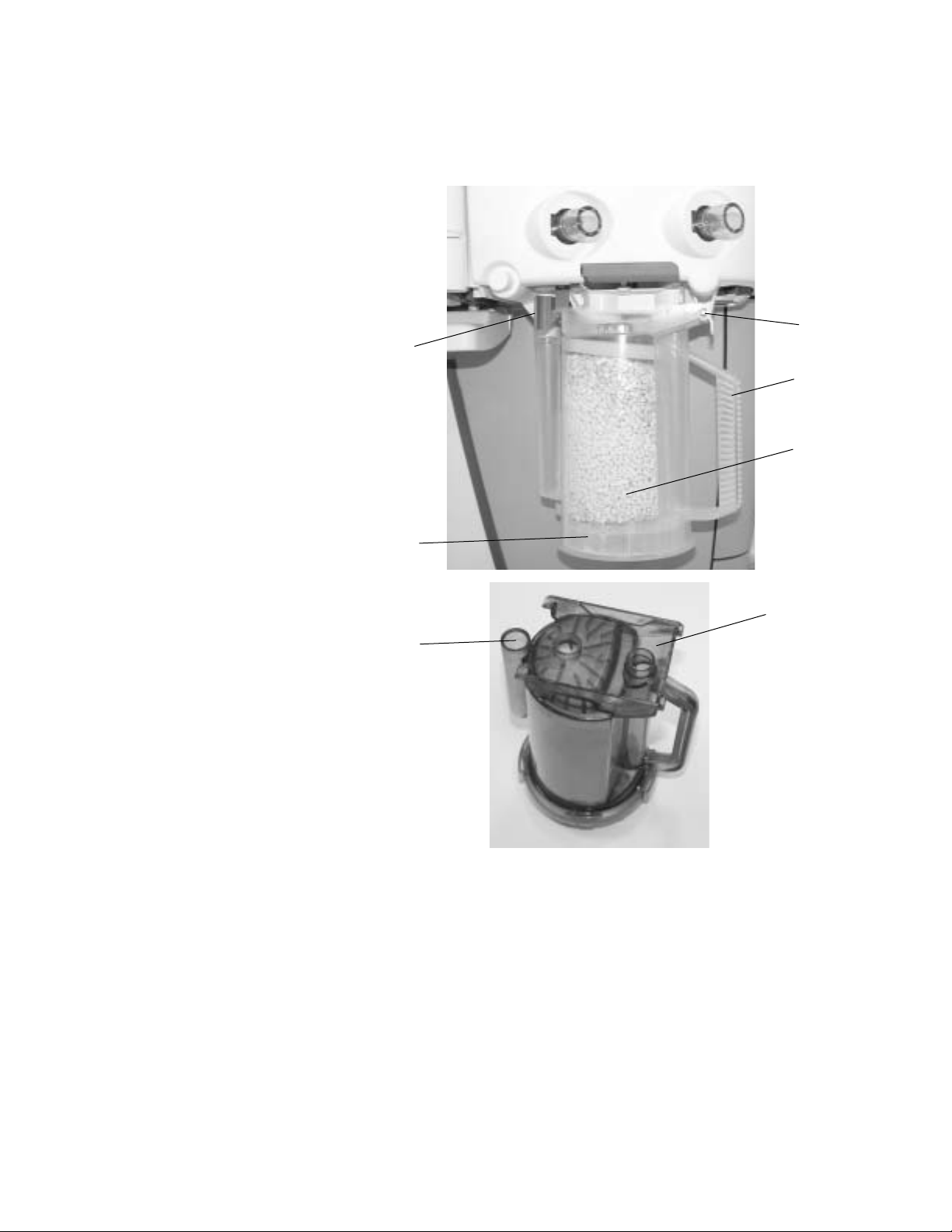
Removing a canister
The absorber canister is available in two versions: Reusable Multi Absorber
and Disposable Multi Absorber. Both are removed and installed on the
breathing system in the same way.
3
2
4
5
1
7
1. Disposable Multi Absorber canister
2. System canister release latch
3. System canister support pin
4. Canister handle
5. Absorbent
6. Reusable Multi Absorber canister
7. Water reservoir
Figure 1-1 • Canister
6
1009-0633-000
1-5
Page 16
Aespire 7900
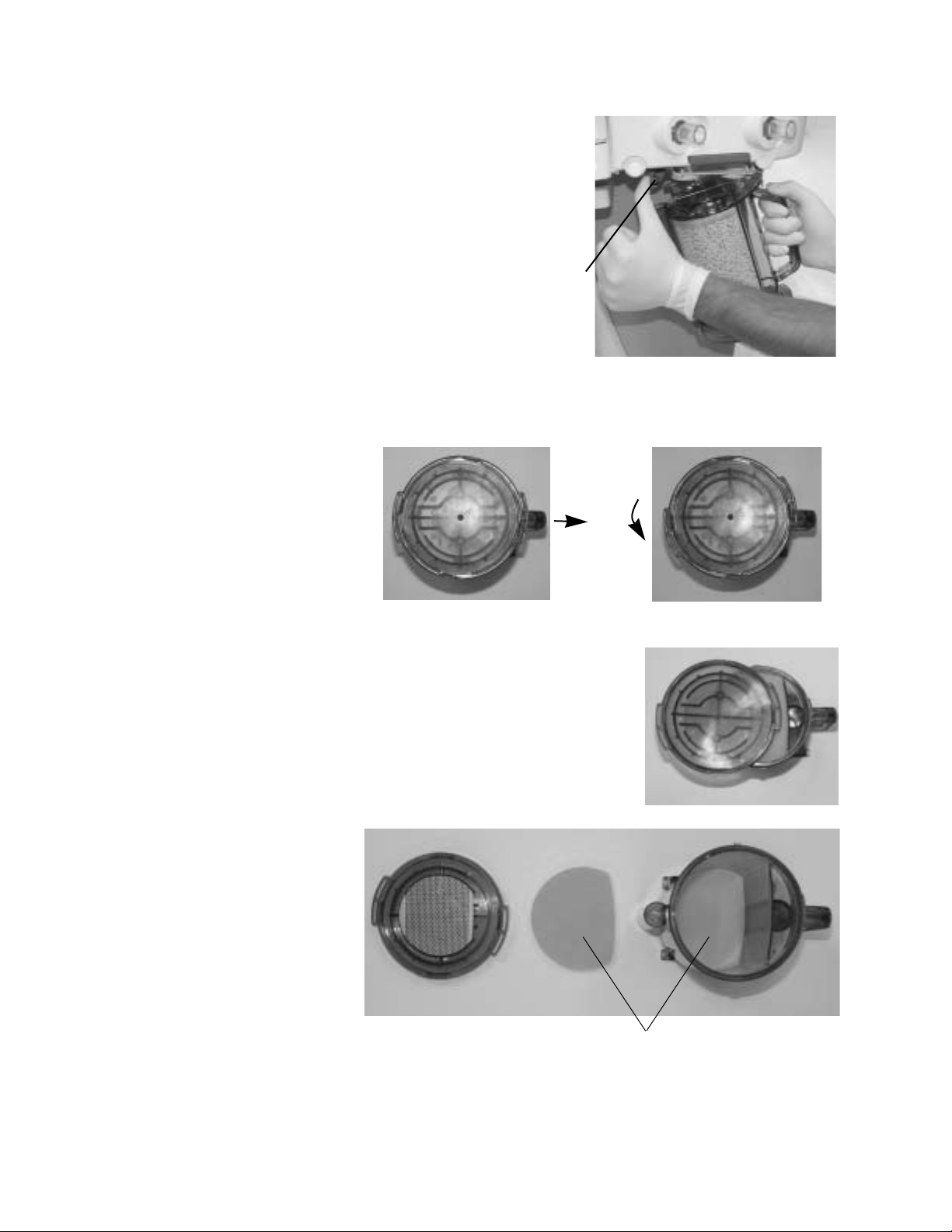
1. Hold the canister by the
handle and push on the
release latch (1) to unlock
the canister.
2. Remove the canister by
tilting it downward and off
the two support pins.
1
Reusable Multi
Absorber canister
filling
1. Turn the canister upside down and, using your thumbs, turn the cover
locking ring counterclockwise to unlock it.
2. Push up with your thumbs to release the seal.
3. Lift off the cover to remove it.
4. Remove and discard the foam filters
(1), the absorbent and any water in the
reservoir.
1-6
1
5. To clean and disinfect the canister, see “Absorber canister” in section 2
Cleaning and Sterilization.”
1009-0633-000
Page 17
1 Setup and Connections
w WARNING
The filters must be in place to prevent dust and particles from
entering the breathing circuit.
6. When dry, place a new filter in the bottom of the canister, pour soda lime
into the canister and place a new filter over the soda lime before closing
and locking the cover. Wipe off any soda lime dust. Align the cover slots
with the canister locking tabs and press the cover down into place. Turn
the cover locking ring clockwise to lock the cover in place. Ensure cover is
properly sealed to prevent leaks and spillage. Alignment of the arrows
helps to indicate correct assembly.
7. When replacing the canister, make sure it is resting on both support pins
before latching it into place.
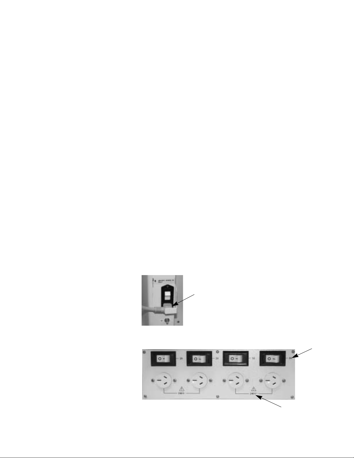
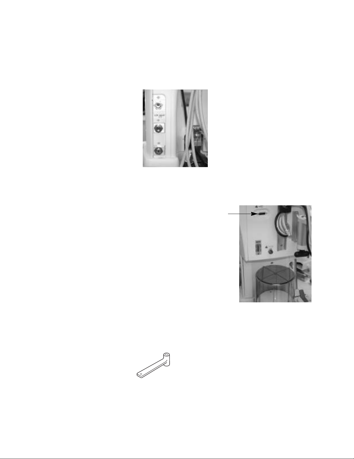
Pneumatic and electrical connections
w WARNING
Equipment connected to the electrical outlets can increase the
leakage current. Regularly test the leakage current.
An optional isolation transformer kit is available to reduce total leakage
current.
w CAUTION
Mains inlet
Outlets
Use only medical grade gas supplies. Other types of gas supplies
may contain water, oil, or other contaminants.
Arrow shows the mains power inlet and cord.
Labels show outlet voltage ratings and circuit breaker amp ratings.
1009-0633-000
1-7
Page 18
Aespire 7900
Pipeline Inlets
The gas supplies also supply these devices through internal connections:
• The venturi suction regulator (optional)
• The auxiliary O
• Ventilator drive gas
flowmeter (optional)
2
Serial port
RS-232C signal standards
The ventilator has an RS-232C electrical interface. The RS-232C connector
allows serial input/output of commands and data.
15-pin Female D connector - Data
Communications Equipment
configuration (DCE):
• Pin 1 - Monitor On/Stby
• Pin 5 - Signal ground
• Pin 6 - Receive data
• Pin 9 - Monitor On/Stby Rtn
• Pin 13 - Transmit data
How to install gas cylinders (high pressure leak test)
Pin indexed cylinder
1. Find the cylinder wrench.
1-8
yokes
1009-0633-000
Page 19
1 Setup and Connections
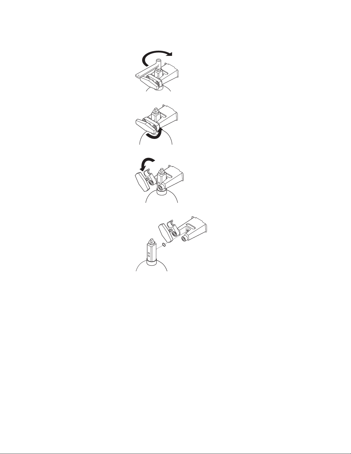
2. Close the cylinder valve on the cylinder to be replaced.
3. Fully loosen the tee handle.
4. Open the cylinder yoke.
w WARNING
5. Remove the used cylinder and the used gasket.
6. Remove the cap from the cylinder valve on the new cylinder.
7. Point the cylinder outlet away from all items that can be damaged by a
release of high pressure gas.
8. Quickly open and close the cylinder valve. This removes dirt from the
cylinder outlet.
No gasket or more than one gasket can cause a leak.
9. Install a new gasket.
10. Align the cylinder post with the index pins.
1009-0633-000
11. Close the yoke gate and tighten the tee handle.
12. Install a cylinder plug and gasket in all empty cylinder yokes.
13. Do a high pressure leak test:
• Disconnect pipeline supplies.
1-9
Page 20
Aespire 7900
• Turn off the auxiliary O
flowmeter and venturi suction.
2
• Set the system switch to Standby.
• Open the cylinder.
• Record the cylinder pressure.
• Close the cylinder.
• If the air or oxygen cylinder pressure decreases more than 5000 kPa
(100 psi) in one minute, there is a significant leak.
• For N
O cylinders, a pressure decrease of 690 kPa (100 psi) in one
2
minute represents a significant leak.
To repair a leak:
• Install a new cylinder gasket and tighten the tee handle.
• Do this step again. If the leak continues, do not use the system.
wCAUTION Do not leave gas cylinder valves open if the pipeline supply is in
use. Cylinder supplies could be depleted, leaving an insufficient
reserve supply in case of pipeline failure.
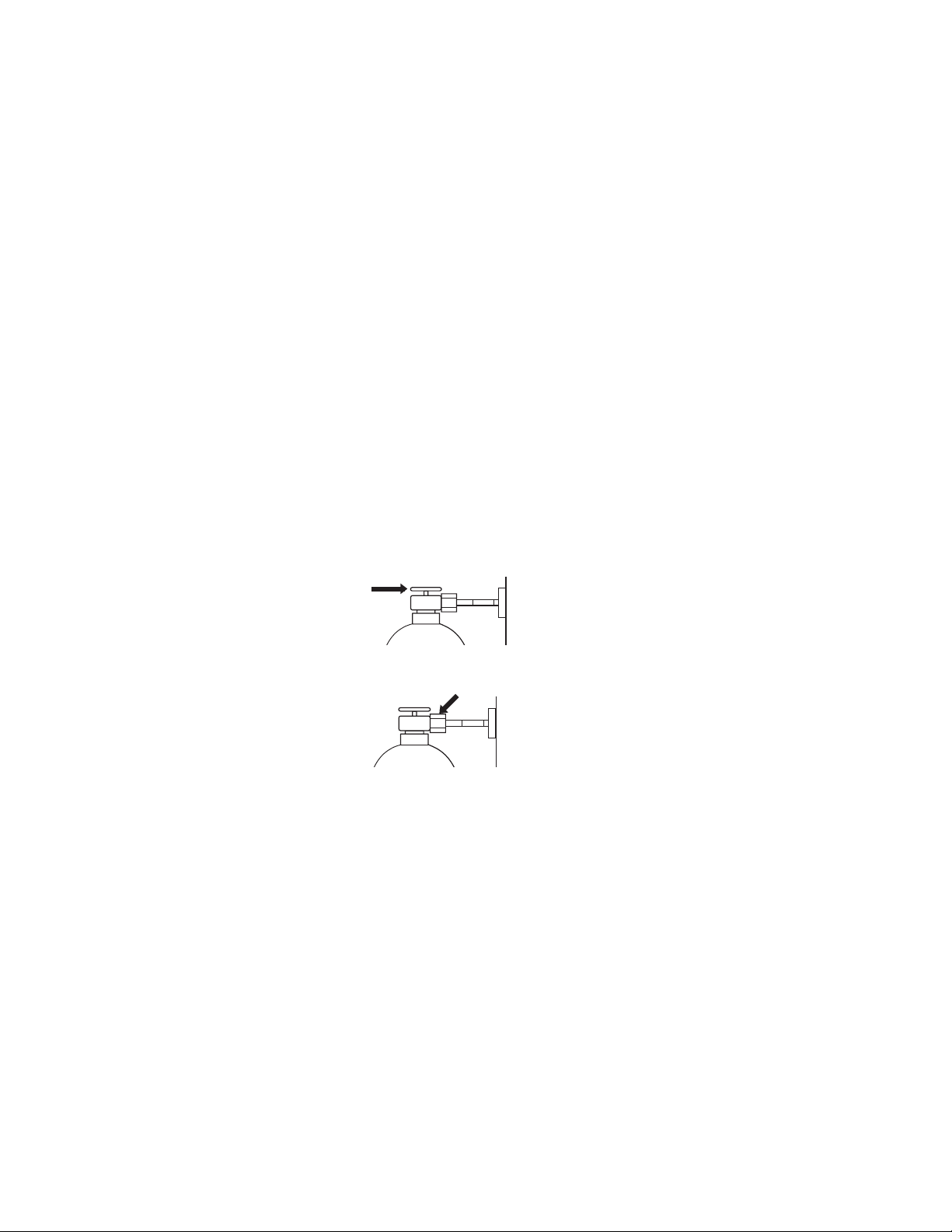
DIN cylinder
1. Close the cylinder valve on the cylinder to be replaced.
connections
2. Loosen the adapter and remove the cylinder.
3. Remove the cap from the cylinder valve on the new cylinder.
4. Point the cylinder outlet away from all items that can be damaged by a
release of high pressure gas.
5. Quickly open and close the cylinder valve. This removes dirt from the
cylinder outlet.
6. Install the cylinder.
7. Do a high pressure leak test:
• Disconnect pipeline supplies.
• Turn OFF the auxiliary flowmeter and the venturi suction.
• Set the system switch to Standby.
• Open the cylinder.
• Record the cylinder pressure.
• Close the cylinder.
1-10
1009-0633-000
Page 21

wWARNING Do not leave gas cylinder valves open if the pipeline supply is in
Installation notes
1 Setup and Connections
• If the cylinder pressure decreases more than 5000 kPa (725 psi) for
O
and air in one minute, there is a significant leak.
2
• For N2O cylinders, a pressure decrease of 690 kPa (100 psi) in one
minute represents a significant leak.
To repair a leak:
• Install a new cylinder gasket and tighten the adapter.
• Do this step again. If the leak continues, do not use the system.
use. Cylinder supplies could be depleted, leaving an insufficient
reserve supply in case of pipeline failure.
When the system is installed, the Datex-Ohmeda representative will check the
following settings and change them if necessary.
wWARNING These settings can only be changed by qualified personnel.
• Language.
• Automatic calculation of VE alarm limits during mechanical ventilation.
• Altitude.
• Ventilator drive gas.
• User Select Defaults.
1009-0633-000 1-11
Page 22

Aespire 7900
How to attach equipment to the top shelf
wWARNING The top shelf has a weight limit of 34 kg (75 lb).
Place the equipment between the straps. Fold the straps over each other and
fully tighten and fasten them with the hook and loop surfaces.
wWARNING If you do not fully tighten the strap, equipment can fall off the
shelf.
1-12 1009-0633-000
Page 23

2 Cleaning and Sterilization
In this section
Breathing system cleanable parts . . . . . . . . . . . . . . . . . . . . . . . . . . . . . . . . . 2-3
Special requirements . . . . . . . . . . . . . . . . . . . . . . . . . . . . . . . . . . . . . . . . . . . 2-4
How to clean and disinfect the flow sensors . . . . . . . . . . . . . . . . . . . . . . . . . 2-4
Remove the breathing system bag hose . . . . . . . . . . . . . . . . . . . . . . . . . . . . 2-6
Remove the breathing system . . . . . . . . . . . . . . . . . . . . . . . . . . . . . . . . . . . . 2-7
Disassemble the breathing system . . . . . . . . . . . . . . . . . . . . . . . . . . . . . . . . 2-8
Disassemble the Bellows assembly . . . . . . . . . . . . . . . . . . . . . . . . . . . . . . . 2-12
Assemble the Bellows assembly . . . . . . . . . . . . . . . . . . . . . . . . . . . . . . . . . 2-14
Bellows assembly tests . . . . . . . . . . . . . . . . . . . . . . . . . . . . . . . . . . . . . . . . . 2-15
Assemble the breathing system . . . . . . . . . . . . . . . . . . . . . . . . . . . . . . . . . .2-18
Install the breathing system . . . . . . . . . . . . . . . . . . . . . . . . . . . . . . . . . . . . .2-22
Remove the AGSS receiver . . . . . . . . . . . . . . . . . . . . . . . . . . . . . . . . . . . . . .2-23
Remove the AGSS receiver filter . . . . . . . . . . . . . . . . . . . . . . . . . . . . . . . . . . 2-24
Absorber canister . . . . . . . . . . . . . . . . . . . . . . . . . . . . . . . . . . . . . . . . . . . . .2-25
1009-0633-000
2-1
Page 24

Aespire 7900
w WARNING Obey applicable safety precautions:
• Read the material safety data sheet for each cleaning agent.
• Read the operation and maintenance manual for all
sterilization equipment.
• Wear gloves and safety glasses. A damaged O
leak and cause burns (contains potassium hydroxide).
• Do not breathe the fumes.
w CAUTION To help prevent damage:
• Refer to the manufacturer’s data if you have questions about a
cleaning agent.
• Do not use organic, halogenated, or petroleum based
solvents, anesthetic agents, glass cleaners, acetone, or other
harsh cleaning agents.
• Do not use abrasive cleaning agents (such as steel wool, silver
polish or cleaner).
• Keep all liquids away from electronic parts.
• Do not permit liquid to go into the equipment housings.
sensor can
22
22
2-2
• Do not soak synthetic rubber parts for more than 15 minutes.
Swelling or faster aging can occur.
• Only autoclave parts marked 134°C.
• Cleaning solutions must have a pH of 7.0 to 10.5.
1009-0633-000
Page 25

Breathing system cleanable parts
1
2 Cleaning and Sterilization
2
3
8
4
7
5
6
1. Bellows assembly
2. APL Valve Ramp
3. APL Diaphragm
4. Breathing circuit module (O
5. Absorber canister (reusable only)
6. Flow sensor cover
7. Flow Sensor Module (plastic flow sensors not autoclavable)
8. Exhalation Valve assembly
sensor not autoclavable)
2
Figure 2-1 • Autoclavable assemblies
Parts marked 134°C are autoclavable or washable by hand or machine (mild
detergent pH <10.5). Rinse and dry completely. All parts except the O
sensor
2
and disposable flow sensors can be washed.
1009-0633-000
If the flow sensors are plastic, refer to the “How to clean and disinfect the flow
sensors” procedure. If metal, they can be autoclaved at 134°C.
2-3
Page 26

Aespire 7900
Special requirements
• To clean the circuit O
sensor in liquid.
• To clean/disinfect metal or plastic flow sensors, use the flow sensor
cleaning procedures. Do not get the connectors wet.
• Disassemble the bellows assembly before you wash it. If not, it will take a
very long time to dry. Hang the bellows upside down (extended) to dry. If
not, the convolutions can stick together.
• Assemble the bellows assembly before you autoclave. Autoclave the
bellows assembly upside down.
sensor, wipe it with a damp cloth. Do not put the
2
w WARNING Do not use talc, zinc stearate, calcium carbonate, corn starch or
equivalent materials to prevent tackiness. These materials can go
into the patient’s lungs and airways and cause irritation or injury.
w CAUTION
w
w
Do not put the circuit O
Do not autoclave the circuit O
Do not clean the interior surfaces of the flow sensors. Use a damp cloth
on external surfaces only.
sensor or flow sensor connector in liquid.
2
sensor or the plastic flow sensors.
2
Inspect all parts for deterioration. Replace them if necessary.
The “Preoperative Tests” section in Part 1 of the User Reference Manual tells
you how to test the system for correct operation.
How to clean and disinfect the flow sensors
w CAUTION Do not autoclave plastic flow sensors.
w Do not use high pressure gas or brushes to clean the flow sensors.
w Do not use cleaning solvents that are not approved for use with
polycarbonates (e.g. CIDEX Plus).
CIDEX sterilization
Both Datex-Ohmeda and the manufacturer of CIDEX (Johnson & Johnson)
have tested this procedure.
• CIDEX must be 14 day mixture, with activator vial (REF reorder #2245).
2-4
1009-0633-000
Page 27

2 Cleaning and Sterilization
• One liter of this solution cleans four (4) flow sensors.
Procedure
1. Pull the latch to unlock the flow sensor module from the breathing
system.
2. Pull the flow sensor module from the breathing system.
3. Remove the flow sensors from the module.
• Completely loosen the thumbscrew (1).
• Pull off the flow sensor cover (3) from the flow sensor holder (2).
• Remove the flow sensor connectors (4) from the flow sensor holder.
• Pull the flow sensors (5) from the flow sensor holder.
1
4
2 3
5
1009-0633-000
2-5
Page 28

Aespire 7900
4. Submerge the flow sensor and
tubes in activated CIDEX
solution. Keep the connector dry.
5. Keep the solution in the tubes for
the sterilization period.
6. Submerge the flow sensor and
tubes in distilled water. Again, do
not get the connector wet.
7. Rinse as indicated in CIDEX
instructions.
8. Do steps 6 and 7 again to remove
all CIDEX.
9. COMPLETELY dry the flow
sensor and the tubes before
you use the sensor. Use a
dry syringe or connect
vacuum or pressure to
remove all liquid from the
sensor (sensor, tubes, and
connector):
w CAUTION Dry for > 1 min with these precautions:
• Maximum flow 10 L/min
• Maximum pressure ±100 cmH
10. Reverse steps 2 and 3 to reassemble the flow sensor module. Be sure to
align the flow sensor tubes with the grooves in the flow sensor holder.
11. Before you use the system, complete the “ Preoperative Tests ” in section
4 of the User Reference Manual, Part 1.
Remove the breathing system bag hose
1. Disconnect the bag hose (1)
from the bag hose connector
(2). Also remove the hose
from the clip (3).
2. If bag arm option is present,
remove the bag port elbow
from the bag arm support.
Push down on the release
latch and slide the bag port elbow out of the holder.
O
2
1
3
2
2-6
1009-0633-000
Page 29
Remove the breathing system
1. Hold the canister (2) by the handle
and push on the release latch (1)
to unlock the canister.
2. Remove the canister by tilting it
downward and off the two support
pins.
3. Push the release
button (3) and
gently pull the
latch handle (4)
to release the
breathing
system.
2 Cleaning and Sterilization
1
2
3
4
4. Lightly grasp the rear handle (5) to support the breathing system. Slide
the breathing system away from the workstation pulling with the latch
handle.
5
1009-0633-000
2-7
Page 30
Aespire 7900
Disassemble the breathing system
The breathing system assembly can be disassembled for cleaning,
sterilization and part replacement.
1. Remove the breathing system and place on a flat surface.
2. Pull the latch to unlock the flow sensor module from the breathing
system.
3. Pull the flow sensor module from the breathing system.
4. Unscrew the sensor counterclockwise and remove it. To remove the
sensor cable from the breathing system, press on the connector button
(1) while pulling the connector out.
1
2-8
1009-0633-000
Page 31

2 Cleaning and Sterilization
5. Remove the flow sensors from the module:
• Completely loosen the thumbscrew (1).
• Pull off the cover (2) from the Flow Sensor Holder (3).
• Remove the flow sensor connectors (4) from the Flow Sensor Holder.
• Pull the flow sensors (5) from the Flow Sensor Holder.
1
2 3
4
5
6. Rotate the breathing circuit module at the point shown by the dotted line.
1009-0633-000
7. After rotating, separate the two sections by pulling them apart.
2-9
Page 32

Aespire 7900
1
8. On the manifold assembly, remove the check valves circuit lens (1) by
squeezing the latches (2) together and pulling up on the lens.
2
9. Press at (2) to unlock the ramp (1). Rotate the ramp and remove the tabs
from the slots (3) to remove the ramp.
10. Lift the diaphragm to remove it.
1
2
3
2-10
1009-0633-000
Page 33

2 Cleaning and Sterilization
11. Turn over the bellows base assembly, grasp the bellows boot with three
fingers in the openings at the points shown and pull straight away to
remove it.
1009-0633-000
2-11
Page 34

Aespire 7900
12. With the breathing system removed, the exhalation valve assembly can
be removed for cleaning if desired. Loosen the two thumbscrews
indicated and lift the assembly off.
Disassemble the Bellows assembly
The bellows assembly can be disassembled for cleaning, sterilization, and
part replacement.
1. Turn the housing counter-clockwise and lift.
2. Remove the bottom edge of the bellows from the rim.
2-12
1009-0633-000
Page 35

2 Cleaning and Sterilization
3. Push the latch toward the center and remove the rim.
4. Remove the pressure-relief valve.
w WARNING Do not disassemble the pressure relief valve. This can damage the
seat or diaphragm and cause injury to the patient.
5. Push the latch toward the center and remove the locking tabs.
6. Remove the seal.
1009-0633-000
2-13
Page 36

Aespire 7900
Assemble the Bellows assembly
1. Install the seal. Verify the arrow on the seal points up.
2. Push the latch toward the center and attach the locking tabs.
3. Install the pressure-relief valve.
4. Push the latch toward the center and install the rim. Verify you hear a
double-click when you install the rim.
2-14
1009-0633-000
Page 37

2 Cleaning and Sterilization
5. Attach the bottom edge of the bellows to the rim. Verify only the bottom
ring of the bellows is fitted over the rim.
6. Lower the housing and turn it clockwise to lock. Verify you cannot lift off of
the housing.
Bellows assembly tests
w WARNING Objects in the breathing system can stop gas flow to the patient.
7. In the above steps, if you see a dust-like powder on the bellows housing
or on the bellows, apply a thin layer of KRYTOX lubricant to the ribs of the
bellows housing. Make sure the lubricant is applied smoothly and there
are no lumps.
8. Perform the Bellows assembly tests before completing the assembly of
the breathing system.
This can cause injury or death:
• Do not use a test plug that is small enough to fall into the
breathing system.
• Make sure that there are no test plugs or other objects caught
in the breathing system.
1009-0633-000
w The bellows assembly test does not replace the preoperative
tests. Always complete the tests in the section Preoperative tests
before you use the system with a patient.
2-15
Page 38

Aespire 7900
This test makes sure that all components are correctly assembled. It is not an
alternative to a complete system checkout.
If the bellows assembly operates correctly, complete the assembly of the
breathing system.
If there is a problem, disassemble the bellows assembly. Look for and replace
damaged parts.
1. Hold the bellows assembly vertical and close the ports (1 and 2).
2
1
2. Invert the bellows assembly. The bellows must not fall within one minute.
If it does:
• The ports are not tightly sealed.
• The bellows is incorrectly installed.
• The seal inside the bellows is not correctly installed (with its groove
pointed up).
• Parts are damaged.
1
2
2-16
1009-0633-000
Page 39

2 Cleaning and Sterilization
3. Remove the plugs from the ports. Permit the bellows to fully extend.
4. Close port 3.
3
5. Hold the bellows assembly upright. The bellows must not fall past the
guide line within one minute. If it does:
• The port is not tightly sealed.
• The bellows or the pressure relief valve is not correctly installed.
• Parts are damaged.
3
1009-0633-000
2-17
Page 40

Aespire 7900
6. If the result for all the bellows assembly tests was “passed,” complete the
assembly of the breathing system.
Assemble the breathing system
1. Replace the exhalation valve assembly as shown. Tighten the two
thumbscrews.
2. Turn over the bellows base assembly. Replace the boot. Be sure to insert
it correctly into the ports as shown by the arrows. Then, press on the
center of the boot (arrow) to snap it into place on the bellows base
assembly.
2-18
1009-0633-000
Page 41

2 Cleaning and Sterilization
3. Replace the diaphragm.
4. Insert the ramp tabs (1) into the slots (2). Rotate the ramp until it locks at
(3).
1
2
3
5. On the manifold assembly, press the check valves circuit lens (1) down
onto the latches (2) to lock the lens.
1
1009-0633-000
2
2-19
Page 42

Aespire 7900
6. Insert the breathing circuit module into the bellows assembly aligned as
shown.
7. Rotate the breathing circuit module at the point shown by the dotted line
to attach it to the bellows assembly.
8. Make sure the o-ring (3) is on the O
screwing it in clockwise. Replace the O
sensor. Replace the sensor (1) by
2
sensor cable connector (2).
2
1
2
9. Attach the flow sensors to the module:
• Insert the flow sensors (1) into the flow sensor holder. Note the
groove locations.
• Attach the flow sensor connectors (2) to the flow sensor holder.
• Attach the cover (4) to the flow sensor holder (3).
• Tighten the thumbscrew (5) to fasten the cover.
3
2-20
1009-0633-000
Page 43

2 Cleaning and Sterilization
2
1
3
4
5
10. Attach the flow sensor module to the breathing system.
11. Push the latch (1) to lock the flow sensor module onto the breathing
system.
1009-0633-000
1
2-21
Page 44

Aespire 7900
12. This is assembled breathing system.
Install the breathing system
1. Locate guide pin openings 1 and 2.
1
2. Align opening 1 onto the guide pin 1, then align opening 2 onto guide pin
2.
12
2
2-22
1009-0633-000
Page 45

2 Cleaning and Sterilization
3. Holding the rear handle (1) and the latch handle (2) as shown, slide the
breathing system onto the guide pins.
1
4. Use the grip under the latch handle to push the breathing system in fully
until it latches firmly.
5. Install the absorber canister and bag hose.
6. Before you use the system, complete the “Preoperative Tests” in section
4 of the User Reference Manual, Part 1.
2
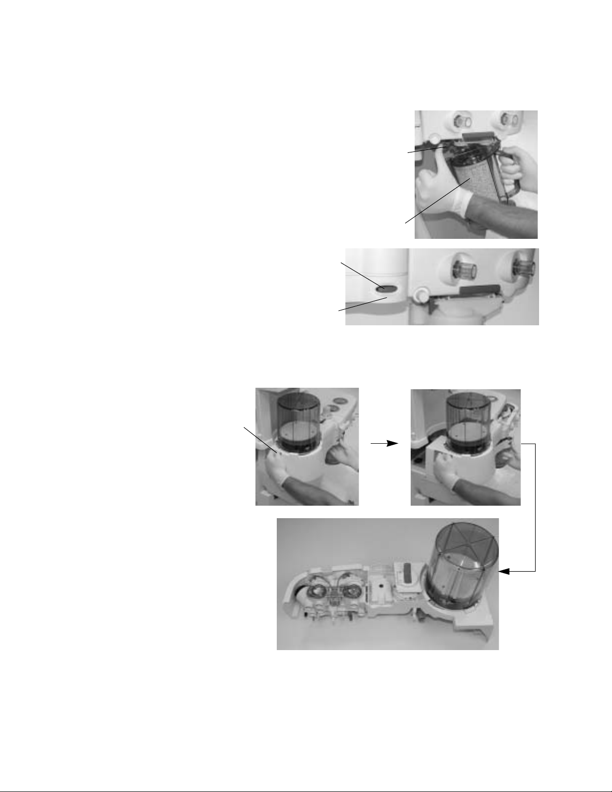
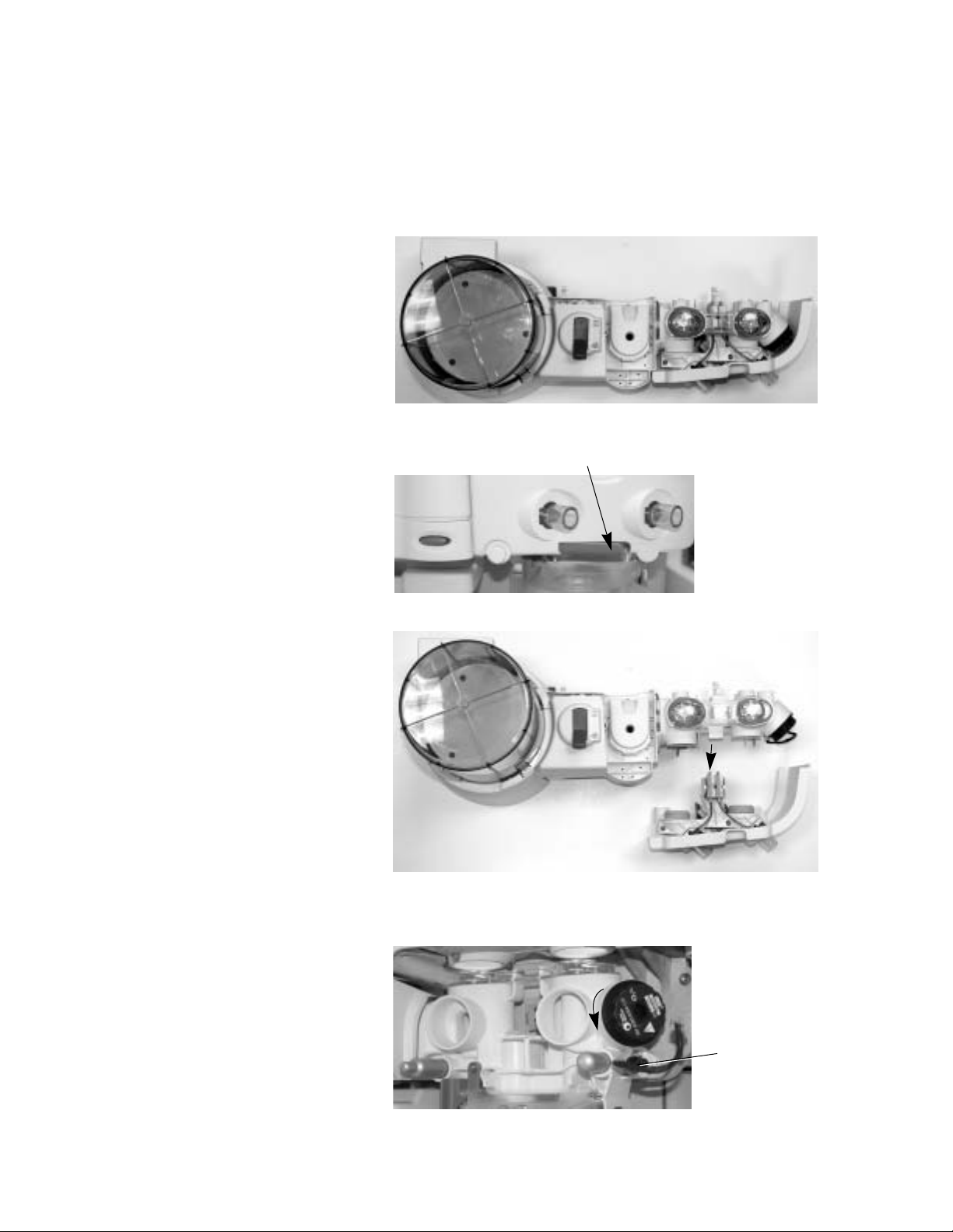
Remove the AGSS receiver
The AGSS receiver may be removed for cleaning and sterilization.
1. On the back of the system, loosen the two thumbscrews (1) to release the
system side panel (2).
2
1
1009-0633-000 2-23
Page 46

Aespire 7900
2. Slide the side panel out by removing its tabs from their slots (1).
1
3. Loosen the thumbscrew and remove the reservoir (2). It is not
autoclavable.
2
4. Loosen the thumbscrew (1) and lower the receiver to remove it.
1
5. Replace the filter as necessary. (See following steps.)
6. Do these steps in the opposite order to replace the receiver and the side
panel.
7. Before you use the system, complete the “Preoperative Tests” in section
4 of the User Reference Manual, Part 1.
Remove the AGSS receiver filter
The AGSS receiver may be autoclaved. To autoclave AGSS receivers which
have a filter, the filter must be removed because it is not autoclavable.
2-24 1009-0633-000
Page 47

1. Pull the flexible gasket (1) from the receiver.
1
2. Pull the filter (1) out of its holder (2).
2
1
2 Cleaning and Sterilization
Absorber canister
wCAUTION The filters must be in place to prevent dust and particles from
3. Do these steps in the opposite order to replace the filter and gasket after
autoclaving the receiver and gasket. Be sure the gasket is firmly pressed
into place at all points.
4. Before you use the system, complete the “Preoperative Tests” in section
4 of the User Reference Manual, Part 1.
The absorber canister is available in two versions: Disposable Multi Absorber
and Reusable Multi Absorber. Both are removed and installed on the
breathing system in the same way.
Refer to “Removing a canister” in section 1 “Setup and Connections”.
Only the Reusable Multi Absorber canister may be cleaned.
entering the breathing circuit.
1009-0633-000 2-25
Page 48

Aespire 7900
Mechanical cleaning in
washer or washer-
disinfector
Manual cleaning 1. Flush the canister and the lid with fresh running water.
1. Place the canister without filters and the lid in the washer or washerdisinfector and clean them with a decontaminating program.
2. Dry the canister and the lid in a warming closet, maximum 80°C (176°F)
or at room temperature.
3. If the washer or washer-disinfector is not used for disinfection of
equipment, Datex-Ohmeda recommends that a further high level
disinfection is conducted.
4. When dry, place a new filter in the bottom of the canister, pour soda lime
into the canister and place a new filter over the soda lime before closing
and locking the cover. Wipe off any soda lime dust.
5. Align the cover slots with the canister locking tabs, and press the cover
down into place. Turn the cover locking ring clockwise to lock the cover in
place. Ensure cover is properly sealed to prevent leaks and spillage.
Alignment of arrows helps to indicate correct assembly.
2. Clean the canister and lid under total immersion in a sink with water and
cleaning agent for at least 3 minutes. The water temperature should be
approximately 40°C (104°F).
3. Flush the canister and lid with fresh running water.
4. When dry, place a new filter in the bottom of the canister, pour soda lime
into the canister and place a new filter over the soda lime before closing
and locking the cover. Wipe off any soda lime dust.
5. Align the cover slots with the canister locking tabs, and press the cover
down into place. Turn the cover locking ring clockwise to lock the cover in
place. Ensure cover is properly sealed to prevent leaks and spillage.
Alignment of arrows helps to indicate correct assembly.
6. Datex-Ohmeda recommends that manual cleaning is always followed by
a high level disinfection.
High level disinfection 1. Always clean the canister before high level disinfection.
2. The canister can be steam autoclaved. Maximum recommended
temperature is 134°C (273°F).
3. When dry, place a new filter in the bottom of the canister, pour soda lime
into the canister and place a new filter over the soda lime before closing
and locking the cover. Wipe off any soda lime dust.
4. Align the cover slots with the canister locking tabs, and press the cover
down into place. Turn the cover locking ring clockwise to lock the cover in
place. Ensure cover is properly sealed to prevent leaks and spillage.
Alignment of arrows helps to indicate correct assembly.
2-26 1009-0633-000
Page 49

3 User Maintenance
w WARNING To help prevent fires:
• Only use lubricants approved for anesthesia or O
equipment,
2
such as Krytox.
• Do not use lubricants that contain oil or grease. They burn or
explode in high O
concentrations.
2
• All covers used on the system must be made from antistatic
(conductive) materials. Static electricity can cause fires.
w WARNING Obey infection control and safety procedures. Used equipment
may contain blood and body fluids.
w WARNING Movable part and removable components may present a pinch or
a crush hazard. Use care when moving or replacing system parts
and components.
In this section
Repair policy . . . . . . . . . . . . . . . . . . . . . . . . . . . . . . . . . . . . . . . . . . . . . . . . . . 3-2
Maintenance summary and schedule . . . . . . . . . . . . . . . . . . . . . . . . . . . . . . 3-2
Breathing system maintenance . . . . . . . . . . . . . . . . . . . . . . . . . . . . . . . . . . . 3-4
1009-0633-000
sensor replacement . . . . . . . . . . . . . . . . . . . . . . . . . . . . . . . . . . . . . . . . . . 3-4
O
2
sensor calibration . . . . . . . . . . . . . . . . . . . . . . . . . . . . . . . . . . . . . . . . . . . 3-5
O
2
Flow sensor zeroing . . . . . . . . . . . . . . . . . . . . . . . . . . . . . . . . . . . . . . . . . . . .3-11
How to prevent water build-up . . . . . . . . . . . . . . . . . . . . . . . . . . . . . . . . . . .3-12
3-1
Page 50

Aespire 7900
Repair policy
Do not use malfunctioning equipment. Make all necessary repairs or have the
equipment serviced by an authorized Datex-Ohmeda service representative.
After repair, test the equipment to ensure that it is functioning properly, in
accordance with the manufacturer’s published specifications.
To ensure full reliability, have all repairs and service done by an authorized
Datex-Ohmeda service representative. If this cannot be done, replacement
and maintenance of those parts listed in this manual may be undertaken by a
competent, trained individual having experience in the repair of devices of this
nature.
w CAUTION No repair should ever be attempted by anyone not having
experience in the repair of devices of this nature.
Replace damaged parts with components manufactured or sold by DatexOhmeda. Then test the unit to ascertain that it complies with the
manufacturer’s published specifications.
Contact your local Datex-Ohmeda Field Service Representative for service
assistance. In all cases, other than where Datex-Ohmeda’s warranty is
applicable, repairs will be made at Datex-Ohmeda’s current list price for the
replacement part(s) plus a reasonable labor charge.
Maintenance summary and schedule
These schedules are the minimum frequency based on typical usage of 2000
hours per year. You should service the equipment more frequently if you use it
more than the typical yearly usage.
User maintenance
Minimum
Frequency
Daily
Weekly
Maintenance
• Clean the external surfaces.
• 21% O
• Flow sensor zeroing.
calibration (circuit O
2
sensor).
2
3-2
Two weeks
• Drain the vaporizers and discard the agent.
This is not necessary for Tec 6 vaporizers.
1009-0633-000
Page 51

3 User Maintenance
Minimum
Frequency
Maintenance
Monthly
During cleaning
and setup
Annually
As necessary
• 100% O
calibration (circuit O
2
sensor).
2
• Put Krytox (or a lubricant approved for use with 100%
O
) on all tee handle threads.
2
• Inspect the parts for damage. Replace or repair as
necessary.
• Replace the external o-rings on the vaporizer ports.
• Install new cylinder gaskets on cylinder yokes.
•Empty the water reservoir and replace the absorbent
in the canister.
•Empty the overflow trap on the optional suction
regulator.
• Replace the circuit O
sensor.
2
(Under typical use the sensor meets specifications for
1 year.)
• Replace the disposable flow sensors (plastic).
(Under typical use the sensor meets specifications for
a miminum of 3 months.)
• Replace the autoclavable flow sensors (metal).
(Under typical use the sensor meets specifications for
a minimum of 1 year.)
• Replace the receiver filter (active gas scavenging
only).
1009-0633-000
Datex-Ohmeda
approved
service
Minimum
Frequency
12 months Have a qualified service person complete the scheduled
Planned Maintenance
service maintenance checks, tests, calibrations and parts
replacement as defined in the service manual.
::
NNNNooootttteeee::
This is the minimum level of maintenance recommended by
Datex-Ohmeda. Local regulations may contain additional
maintenance requirements. Datex-Ohmeda advocates
compliance with local regulations which meet or exceed this
minimum level of maintenance.
3-3
Page 52

Aespire 7900
Breathing system maintenance
When cleaning the breathing system, replace any parts that are visibly
cracked, chipped, distorted or worn.
Refer to the appropriate section for reassembly and tests.
O
sensor replacement
2
w WARNING Handle and dispose of sensors according to your biohazard
policies. Do not incinerate.
1. Pull the latch (1) to unlock the flow sensor module from the breathing
system.
1
2. Pull the flow sensor module from the breathing system.
3. Remove the O
unscrew the sensor counterclockwise. Don’t lose the sensor o-ring.
sensor cable connector (2) from the O
2
sensor (1) and
2
1
2
3-4
1009-0633-000
Page 53

3 User Maintenance
4. Make sure the o-ring (1) is on the sensor. Install the replacement O
sensor. Reconnect the O
5. Replace the flow sensor module on the system and press the latch (1) in
to secure the module.
sensor cable.
2
1
1
2
O
sensor calibration
2
w WARNING Do not perform calibration while unit is connected to a patient.
21% O
sensor
2
calibration
w The O
sensor must be calibrated at the same environment
2
pressure at which it will be used to monitor oxygen delivery in the
patient circuit.
w Operation at pressures other than the pressures present during
calibration may result in readings outside of the stated monitoring
accuracy.
This procedure takes three minutes or less.
You must do the 21% O
calibration the screen replaces O
calibration before the 100% O
2
data with ---- --
2
--
.
calibration. During O
2
2
1009-0633-000
3-5
Page 54

Aespire 7900
Step 1
Push the Menu key to see
the main menu.
Step 2
Turn the knob to select the
Calibration screen.
Step 3
Push the knob to show the
next screen.
Step 4
Turn and push the knob to
select O
Sensor Cal.
2
Step 5
Select 21% then push the
knob.
3-6
1009-0633-000
Page 55

Step 6
Complete the steps shown
on the screen.
To remove the O
from the circuit:
sensor
2
• Pull the latch (1) to
unlock the flow
sensor module from
the breathing
system.
3 User Maintenance
1
• Pull the flow sensor
module (2) from the
breathing system.
• Remove the O
2
sensor (3) and leave
it exposed to room
air.
2
3
1009-0633-000
3-7
Page 56

Aespire 7900
Step 7
Select Start Cal and push
the knob to start calibration.
• The screen shows
After a successful calibration, the screen shows “Complete” and a flashing “Reinstall Sensor”.
After installing the sensor, you can continue to 100% calibration (step 11) or exit to the normal screen (step 7).
“ CCCCaaaalllliiiibbbbrrrraaaattttiiiinnnngg
gg
” during
the procedure.
An unsuccessful calibration shows “ FFFFaaaaiiiilllluuuurrrree
ee
”. If the calibration fails:
• Do the calibration again.
• If it still fails, do a 100% O
sensor calibration (step 11). If 100% O
2
at 21% again.
• After repeated failures, replace the O
Step 8
To exit, select “Go to Cal
Menu” and push the knob.
You can also press
the menu key to exit to
the normal screen.
Select “Go to Main Menu”
and push the knob.
Step 9
Select “Exit to Normal
Screen” and push the knob.
2
sensor and re-calibrate at 21%.
2
Go to Main Menu
Exit to Normal Screen
sensor calibration passes, calibrate
3-8
Step 10
If you are not doing the 100% calibration which follows, do a breathing circuit leak test before using the system.
1009-0633-000
Page 57

3 User Maintenance
100% O
sensor
2
calibration
w WARNING Do not perform calibration while unit is connected to a patient.
Step 11
Turn then push the knob to
select O
Step 12
Select 100% then push the
knob.
Sensor Cal.
2
This procedure takes three minutes or less.
You must complete the 21% calibration before you can select the 100%
calibration.
Step 13
With the O
circuit, fill the circuit with
100% O
sensor in the
2
:
2
• Push the flush
button.
•
Then
flow 100% O
5 L/min. (Circuit should
be open.)
Step 14
Select Start Cal. Then push
the knob to start calibration.
at
2
1009-0633-000
3-9
Page 58

Aespire 7900
The screen shows ‘Calibrating ... ‘, followed by the result: ‘Complete’ or ‘Failure’.
If the calibration fails,
• do it again or
• decrease the airway pressure. Then try again.
After repeated failures replace the O
Continue with steps 14 through 16 to exit to a normal screen.
Step 15
To exit, select “Go to Cal
Menu” and push the knob.
You can also press
the menu key to exit to
the normal screen
Step 16
Select “Go to Main Menu”
and push the knob.
sensor and re-calibrate at 21%.
2
Go to Cal Menu
Go to Main Menu
Step 17
Select “Exit to Normal
Screen” and push the knob.
Step 18
Do a breathing circuit leak test before using the system.
Exit to Normal Screen
3-10
1009-0633-000
Page 59

Flow sensor zeroing
wWARNING Do not perform calibration while unit is connected to a patient.
3 User Maintenance
The system automatically corrects for zero offset when you unplug the flow
sensor connectors with power on. You must stop mechanical ventilation
before you calibrate the flow sensors.
Note: Properly performing the O2 cell zeroing will also zero the flow sensor.
Step 1
Pull the latch (1) to unlock the
flow sensor module from the
breathing system.
Step 2
Pull the flow sensor module from
the breathing system.
Step 3
When zeroing is complete, the
screen shows, “No Insp flow
sensor” and “No Exp flow
sensor.”
1
NNNNoooo IIIInnnnsssspppp FFFFlllloooowwww SSSSeeeennnnssssoooorr
NNNNoooo EEEExxxxpppp FFFFlllloooowwww SSSSeeeennnnssssoooorr
rr
rr
Step 4
Install the flow sensor module.
Step 5
Do a breathing circuit leak test before using the system. Refer to “Breathing system tests” in section 4 Preoperative Tests of the
User Reference Manual, Part 1.
1009-0633-000
3-11
Page 60

Aespire 7900
How to prevent water build-up
Why is water buildup a
problem?
How much water is
acceptable?
Where does the water
come from?
Solutions: •Empty the water reservoir in the canister when changing the soda lime.
Pooled water in the flow sensor or water in the sensing lines causes false
alarms.
Small beads of water or a foggy appearance in the flow sensors is OK.
Water comes from exhaled gas and a chemical reaction between CO2 and the
absorbent in the absorber.
At lower fresh gas flows more water builds up because less gas is scavenged
and:
• More CO
• More moist, exhaled gas stays in the absorber.
• Ensure that water condensing in the breathing circuit tubes is kept lower
than the flow sensors and is not allowed to drain into the flow sensors.
stays in the absorber to react and produce water,
2
•Water condensation in the breathing circuit tubing can be eased using a
Heat & Moisture Exchange (HME) filter at the airway connection.
3-12 1009-0633-000
Page 61

4 Alarms and Troubleshooting
w CAUTION No repair should ever be attempted by anyone not having
experience in the repair of devices of this nature.
In this section
About alarms . . . . . . . . . . . . . . . . . . . . . . . . . . . . . . . . . . . . . . . . . . . . . . . . . . 4-2
Alphabetical list . . . . . . . . . . . . . . . . . . . . . . . . . . . . . . . . . . . . . . . . . . . . . . . . 4-4
Breathing system problems (no alarm) . . . . . . . . . . . . . . . . . . . . . . . . . . . . 4-13
Electrical problems (power failure, etc.) . . . . . . . . . . . . . . . . . . . . . . . . . . .4-14
Pneumatic problems . . . . . . . . . . . . . . . . . . . . . . . . . . . . . . . . . . . . . . . . . . .4-16
Alarm settings range and default values . . . . . . . . . . . . . . . . . . . . . . . . . . .4-17
1009-0633-000
4-1
Page 62

Aespire 7900
About alarms
w WARNING If an alarm occurs, safeguard the patient first, before
troubleshooting or repair procedures.
Two areas on the screen show alarms. The area at the top of the display shows
most alarms. If there are more than 4 alarms at the same time, the lower
priority alarms cycle every two seconds.
During severe malfunctions that prevent mechanical ventilation and/or
monitoring, the area under the waveform shows minimum system messages.
During normal operation, this area shows instructions (push the knob, etc.).
Alarms
Alarm priority depends on the level of danger to the patient. High priority
alarms require immediate attention.
Priority Alarm tone Alarm silence Note
High 10 tones,
10 second pause,
repeat
Medium 3 tones,
25 second pause,
repeat
Low Single tone Tone does not repeat ---
120 seconds or cannot
be silenced
120 seconds ---
Reverse video
AB.90.025
4-2
Page 63

4 Alarms and Troubleshooting
Alarm messages have three general causes.
• Malfunctions: Some malfunctions cause reduced function (for example,
no PEEP). Others prevent mechanical ventilation (Minimum shutdown).
• Patient monitoring: These are high and low limit settings that you adjust.
• Informational: Control settings or system conditions can change
operation. For example, if the audible circuit leak alarm is Off, the screen
shows “Circuit Leak Audio Off” as a low priority alarm.
1009-0633-000
4-3
Page 64

Aespire 7900
Alphabetical list
The instructions in this section tell you what you can do:
• During a case to protect the patient
• After the case to repair a problem
This table does not include operator instructions.
There are two special types of alarms:
• Minimum monitoring alarms stop mechanical ventilation.
• Minimum shutdown alarms stop mechanical ventilation and monitoring.
Message Priority Cause Action/Concerns Repair
+15V Analog Out-ofRange
-15V Analog Out-ofRange
12 Hour Test Low System in use for more than
A/D Converter
Failure
Absorber panel open Medium The top panel is not
Adjust Low Ve Limit Medium The audible circuit leak
Min. shutdown
(High)
Min. shutdown
(High)
Min. shutdown
(High)
Ventilator malfunction. Ventilate manually. Monitoring is
Ventilator malfunction. Ventilate manually. Monitoring is
12 hours without a power-up
self test.
Ventilator malfunction. Ventilate manually. Monitoring is
completely closed.
alarm is Off (Alarm menu)
but the low VE alarm is not
set.
VE alarm is Off in SIMV or
PSVPro modes.
Contact a qualified
not reliable.
not reliable.
To do the test, move the system
switch from Standby to On.
not reliable.
Push the breathing system into
the frame and ensure it latches.
Increase the low VE alarm limit. - - -
service representative.
Contact a qualified
service representative.
Not necessary,
informational.
Contact a qualified
service representative.
- - -
Apnea Alarm
Standby
Apnea Alarm Off Low The cardiac bypass option is
4-4
Low Normal condition after End
Case, power-up, or ACGO
change from On to Off
selected (alarm limit menu).
Monitoring resumes after first
breath (mechanical) or 2 breaths
within 30 seconds (nonmechanical).
Apnea alarms are normally
turned off when this option is
selected.
- - -
- - -
Page 65

4 Alarms and Troubleshooting
Message Priority Cause Action/Concerns Repair
Aux Gas Outlet On Medium
(low after
acknowledged)
The outlet selection switch is
set to the auxiliary common
gas outlet.
Backup Mode Active Low SIMV-PC + PSV mode
entered.
Battery Charger Fail Low The current in the battery
charging circuit is too high.
Battery Charging Low The battery is not fully
charged. If power fails, the
total backup time will be less
than 30 minutes.
Battery Current High Low Battery current >
6
amps
for
10 seconds.
Battery Failure High Low Battery voltage > 16 V for 10
seconds.
Connect the patient circuit to the
auxiliary outlet. For mechanical
ventilation or manual ventilation
with monitoring, select the
breathing system.
Spontaneous breath rate fell
below the set breath rate
The system is operational, but
may fail later depending on what
caused this alarm.
Leave the system plugged in to
charge the battery.
The system continues to operate,
but may fail.
The system continues to operate,
but may fail.
- - -
- - -
Contact a qualified
service representative.
- - -
Contact a qualified
service representative.
Contact a qualified
service representative.
Battery Failure Low Low The battery voltage is too low
(<7 V) to supply the system if
power fails.
Cal Flow Sensors Low The last flow sensor
calibration failed.
Calibrate O2 Sensor Low O
%>110% Does the sensor measure 21%
2
Cannot Drive Bellows Low The internal manifold
pressure is higher than Paw
+ tolerance.
Cardiac Bypass Low The alarm limit settings are
set for a patient on cardiac
bypass. Apnea alarms are
off.
The battery does not have
enough charge to power the
equipment if power fails.
Leave the system plugged in to
If the battery does not
charge in 24 hours,
contact a service
representative.
charge the battery.
Calibrate the flow sensors. Look
for water in the flow sensor
Contact a qualified
service representative.
tubes. Dry if necessary.
Calibrate O
O
in room air?
2
Fill the bellows if empty. - - -
Use the alarm limits menu to
- - -
change this setting.
sensor.
2
1009-0633-000
4-5
Page 66

Aespire 7900
Message Priority Cause Action/Concerns Repair
Check Flow Sensors Medium
(low after
acknowledged)
Circuit Leak Audio
Low Control setting on the Alarm
Off
Connect O
Sensor Low The O
2
CPU Failure Minimum
shutdown (High)
CPU Internal Error Minimum
shutdown (High)
Display Voltage OutOf-Range
Minimum
shutdown (High)
No flow or negative flow on
inspiratory sensor during
Are the flow sensors correctly
installed?
inspiration in a circle system
or negative flow on
expiratory sensor in
Water build-up in the flow sensor
tubes?
expiration (for 6 breaths in a
row).
Is a flow sensor tube cracked or
broken?
This message tells you that the
limit menu.
audio alarm for circuit leaks was
turned off.
sensor is not
2
Connect the sensor. Contact a qualified
connected to the cable.
Ventilator malfunction. Ventilate manually. Monitoring is
not reliable.
Ventilator malfunction. Ventilate manually. Monitoring is
not reliable.
Ventilator malfunction. Ventilate manually. Monitoring is
not reliable.
Inspect one way valves
(breathing circuit
module).
Replace flow sensor
module. Check the
condition of the flow
sensor and its tubing.
- - -
service representative
to replace the cable.
Contact a qualified
service representative.
Contact a qualified
service representative.
Contact a qualified
service representative.
Exp Flow Sensor Fail Low The system cannot read the
calibration data stored in the
sensor.
Exp Reverse Flow Medium
(low after
acknowledged)
Flow Valve (DAC)
Failure
Flow Valve (current)
Minimum
monitoring
(Medium)
Flow through the expiratory
sensor during inspiration (for
6 breaths in a row).
Ventilator malfunction. Ventilate manually. Monitoring is
Failure
Gas Inlet Valve
Failure
Hardware Watchdog
Failure
Minimum
shutdown (High)
Minimum
shutdown (High)
Ventilator malfunction. Ventilate manually. Monitoring is
a
Ventilator malfunction. Ventilate manually. Monitoring is
Operation continues with default
values.
Replace the flow sensor.
Look at the check valves.
Water build-up in the flow sensor
tubes?
Is a flow sensor tube cracked or
broken?
still available.
still available.
not reliable.
- - -
Replace the expiratory
check valve.
Check the condition of
the flow sensor.
Contact a qualified
service representative.
Contact a qualified
service representative.
Contact a qualified
service representative.
4-6
Page 67

4 Alarms and Troubleshooting
Message Priority Cause Action/Concerns Repair
High O
2
Medium O
% > alarm high limit
2
setting.
High Paw High Paw is greater than Plimit.
The ventilator cycles to
expiration.
High Ve Medium The minute volume is greater
than the set high limit. This
alarm is suspended for 9
breaths or one minute after
you change the ventilator
settings.
High Vte Medium VTE is greater than high
alarm limit. This alarm is
suspended for 9 breaths
after you change the
ventilator settings.
Is the limit set correctly? What is
the O
flow?
2
Did you just push Flush? Does
the sensor see 21% O
in room
2
air?
Are Plimit and other controls set
correctly? Look for blockages.
Check the patient connection.
Check patient for spontaneous
breathing. Adjust control
settings.
Check patient for spontaneous
breathing. Check ventilator and
alarm settings.
Calibrate O
Replace O
sensor.
2
sensor.
2
Calibrate the flow
sensors.
Replace the receiver
filter.
- - -
- - -
Insp Flow Sensor Fail Low The system cannot read the
calibration data stored in the
sensor.
Inspiration Stopped High Drive gas safety switch
activated (high internal
pressure)
Insp Reverse Flow Medium
(low after
acknowledged)
Internal Ventilator
Clock Too Fast
Internal Ventilator
Clock Too Slow
Invalid Circuit
Minimum
shutdown (High)
Minimum
shutdown (High)
Low Ventilator malfunction. Ventilate manually; monitoring is
Flow through the inspiratory
sensor during expiration (for
6 breaths in a row).
Ventilator malfunction. Ventilate manually. Monitoring is
Ventilator malfunction. Ventilate manually. Monitoring is
Module
Operation continues with default
values.
Replace the flow sensor.
Adjust controls. Check systems
for blockages.
Look at the check valves.
Water build-up in the flow sensor
tubes?
Is a flow sensor tube cracked or
broken?
not reliable.
not reliable.
not reliable.
- - -
- - -
Replace the inspiratory
check valve.
Check the condition of
the flow sensor.
Contact a qualified
service representative.
Contact a qualified
service representative.
Contact a qualified
service representative
1009-0633-000
4-7
Page 68

Aespire 7900
Message Priority Cause Action/Concerns Repair
Limit Task Light Use Low The system is running on
battery power. Turn off the
light to save power.
Loss of Backup
Audio
Medium
(low after
The audio alarm will not
sound for a CPU failure.
acknowledged)
Low Battery Voltage Medium Voltage is <11.65V while
using battery power.
Low Drive Gas Pres Medium The ventilator did not detect
a rise in internal pressure
when the flow valve opened.
Low O
2
High O
% < alarm low limit setting Is the limit set correctly? Is the
2
Turn off the light to extend
- - -
battery backup.
Monitor system operation. Contact a qualified
service representative.
Manually ventilate the patient to
save power.
Make sure power is
connected and circuit
breakers are closed.
Contact a qualified
service representative.
Manually ventilate the patient. Make sure that the
appropriate gas
supplies (O
or Air) are
2
connected and
pressurized.
O
flow sufficient? Does the
2
sensor see 21% O
in room air?
2
Calibrate O
Replace O
sensors wear out, the
measured % O
sensor.
2
sensor. As
2
2
decreases.
Low Paw Medium Paw does not rise at least 4
cm from the lowest pressure
measured during the last 20
seconds.
Low Ve Medium Exhaled minute volume <low
limit alarm setting. This
alarm is suspended for 9
breaths or one minute after
you change the ventilator
settings.
Low Vte Medium Exhaled tidal volume <low
limit alarm setting. This
alarm is suspended for 9
breaths after you change the
ventilator settings.
Manifold Pressure
Sensor Failure
Minimum
monitoring
Ventilator malfunction. Ventilate manually. Contact a qualified
(Medium)
Are circuit connections OK? Look
at the Paw gauge on the
absorber.
Check patient condition. Check
tubing connections.
Check alarm settings.
Check patient condition. Check
tubing connections. Check alarm
settings.
Look for circuit
disconnection.
- - -
- - -
service representative.
4-8
Page 69

4 Alarms and Troubleshooting
Message Priority Cause Action/Concerns Repair
Memory (EEPROM)
Fail
The system cannot access
some stored values.
Default settings are used.
Ventilation is still possible but
Contact a qualified
service representative.
service is necessary.
Memory (flash)
Failure
Memory (RAM)
Failure
Memory (Redundant
Storage) Fail
Minimum
shutdown (High)
Minimum
shutdown (High)
Minimum
monitoring
Ventilator malfunction. Ventilate manually. Monitoring is
not reliable.
Ventilator malfunction. Ventilate manually. Monitoring is
not reliable.
Ventilator malfunction. Ventilate manually. Monitoring is
still available.
Contact a qualified
service representative.
Contact a qualified
service representative.
Contact a qualified
service representative.
(Medium)
Memory (video)
Failure
Monitoring Only Medium A severe malfunction
Minimum
shutdown (High)
Ventilator malfunction. Ventilate manually. Monitoring is
not reliable.
Ventilate manually. Cycle system
prevents mechanical
ventilation. Other alarms
may also occur.
power (On- Standby-On). If the
alarm clears, restart mechanical
ventilation.
Contact a qualified
service representative.
Contact a qualified
service representative.
No Circuit Module Low Ventilator malfunction. Ventilate manually. Optical sensors look for
tabs on the back of the
module. Is the module
assembled? are the
sensors dirty?
No CO
Absorption Medium
2
No Exp Flow Sensor
No Insp Flow Sensor
No message, only
specific shutdown
message
No O
Pressure High
2
The absorber canister is
(low after
acknowledged)
open (out of the circuit) but
the bypass mechanism
prevents a leak (optional
feature).
Medium
(low after
acknowledged)
Electrical signals show the
flow sensor is not
connected.
High A severe malfunction
prevents mechanical
ventilation and monitoring.
Other alarms may also
occur.
The O
supply has failed. Air flow will continue. Ventilate
2
(cannot be
silenced)
User setting. Reinstall the
absorber canister to remove CO
from exhaled gas
Connect the flow sensors. Make
sure the flow sensor module is
on all the way.
Ventilate manually. Use a stand-
alone monitor. Cycle system
power (On- Standby-On). If the
alarm clears, restart mechanical
ventilation.
manually if necessary. Connect a
pipeline supply or install an O
2
cylinder.
- - -
2
- - -
Contact a qualified
service representative
- - -
1009-0633-000
4-9
Page 70

Aespire 7900
Message Priority Cause Action/Concerns Repair
O
Flush Failure Low The pressure switch that
2
detects flush flow has seen a
very long flush (≥30
seconds).
O
Sensor out of
2
Low Ventilator malfunction. Ventilate manually. Contact a qualified
circuit
This alarm occurs if you hold
down the Flush button for more
than 30 seconds.
If the alarm occurs
when flush is not in
use, contact a qualified
service representative.
service representative.
On Battery - Power
OK?
Medium
(low after
acknowledged)
The mains supply is not
connected or has failed and
the system is using battery
power.
Patient Circuit Leak? Medium Exhaled volume <50% of
inspired volume for at least
30 seconds (mechanical
ventilation).
Paw < -10 cmH
O High Subatmospheric pressure
2
(<-10 cmH
O).
2
PEEP Not Achieved Low Pmin does not reach within
±
2 cmH
O of PEEP by the
2
end of mechanical
expiration for 6 consecutive
breaths.
Positive SIB Vref Outof- Range
Minimum
shutdown (High)
Ventilator malfunction. Ventilate manually. Monitoring is
Ventilate manually to save
power. At full charge, the battery
permits approx. 30 minutes of
mechanical ventilation.
Check breathing circuit and flow
sensor connections.
Check patient condition,
spontaneous activity? Increase
fresh gas flow. Look for high flow
through gas scavenging.
Check tubing connections. Rate
and/or I:E ratio may prevent
ventilator from reaching desired
PEEP level.
not reliable.
Make sure power is
connected and circuit
breakers are closed.
- - -
Calibrate the flow
sensors.
b
With active
scavenging, check the
negative relief valve on
the receiver.
- - -
Contact a qualified
service representative.
Pres Mode Not Avail Medium
(Pressure,
PSVPro and SIMV
modes)
Low (Volume
mode)
Pres/Vol Mon
Medium Outlet selection switch is set
Inactive
4-10
Manifold pressure not
tracking airway pressure, or
manifold pressure
≤ -15 cmH
O.
2
to auxiliary gas outlet.
Pressure control mode and PEEP
are not available. Switch to
Volume mode or ventilate
manually.
Check patient for spontaneous
breathing.
Check ventilator settings.
Connect the patient circuit to the
auxiliary gas outlet or set the
switch to the circle breathing
system.
Contact a qualified
service representative.
- - -
Page 71

4 Alarms and Troubleshooting
Message Priority Cause Action/Concerns Repair
Pressure Limit Switch
Failure
Replace O
Sensor Low O
2
Minimum
monitoring
(Medium)
A pressure safety switch
activated at a Paw <90
cmH
O and Pmanifold <80
2
cm H
O.
2
% < 5% Makes sure patient receives O
2
Select Gas Outlet Medium Fresh gas may not flow to the
patient. Auxiliary gas outlet
is On, but flow sensors have
seen 3 breaths in patient
circuit during the last 30
seconds.
Service Calibration Low Internal calibrations are
necessary for maximum
accuracy.
Software Error Minimum
Ventilator malfunction. Ventilate manually. Monitoring is
shutdown (High)
Ventilate manually. Monitoring is
still available. Extreme control
combinations may cause this
alarm.
Check control settings.
.
2
Does the sensor see 21% O
in
2
room air? Use different monitor.
Select the circle breathing
system or connect the patient
circuit to the auxiliary outlet.
The system is operational.
Operation continues with default
values.
not reliable.
Contact a qualified
service representative.
Calibrate O
Replace O
sensor.
2
sensor.
2
Note: the bag arm will
not ventilate a patient
at the auxiliary outlet.
Contact a qualified
service representative.
Contact a qualified
service representative.
Software Watchdog
Failure
Sustained Airway
Pressure
Minimum
shutdown (High)
Minimum
shutdown (High)
Ventilator malfunction. Ventilate manually. Monitoring is
Paw > 100 cmH
O for 10
2
seconds.
Sustained Paw High Paw > sustained pressure
limit for 15 seconds
c
.
System Leak? Medium Delivered volumes do not
match set volumes.
Vaux_ref Out-ofRange
Vext_ref Out-ofRange
Minimum
shutdown (High)
Minimum
shutdown (High)
Ventilator malfunction. Ventilate manually. Monitoring is
Ventilator malfunction. Ventilate manually. Monitoring is
not reliable.
Check tubing for kinks,
blockages, disconnects.
Check tubing for kinks,
blockages, disconnects.
Look for leaks in the breathing
system. Compare set to
delivered volumes.
not reliable.
not reliable.
Contact a qualified
service representative.
Calibrate the flow
sensors.
Calibrate the flow
sensors.
Calibrate the flow
sensors.
Drain water buildup
from the breathing
system.
Contact a qualified
service representative.
Contact a qualified
service representative.
1009-0633-000
4-11
Page 72

Aespire 7900
Message Priority Cause Action/Concerns Repair
Volume Apnea Medium No mechanical breaths or
spontaneous breaths >20
mL in last 30 seconds.
Check patient. Bag as needed.
Check for disconnects. If the
patient is on a heart lung
- - -
machine, select Cardiac Bypass
on the main menu.
Vol Apnea > 2 min High No mechanical breaths or
See above. - - spontaneous breaths >20
mL in last 120 seconds.
Vt Not Achieved Low Tidal volume measured by
inspiratory flow sensor
< set value 6 breaths in a
Adjust controls to supply
adequate tidal volumes. Check
I:E; Plimit; and volume settings.
Possible leak.
row after the first minute of
mechanical ventilation.
Vte > Insp Vt Medium Expired volume > inspired
Check patient condition. - - volume for 6 breaths with a
circle breathing system.
a. When power is first turned on.
b. Flow sensors are also used to measure pressures.
c. The sustained pressure threshold is calculated from the pressure limit setting. When mechanical ventilation is
on, the sustained limit is calculated as follows: for pressure limits < 30 cmH
cmH
O; for Plimit between 30 and 60 cmH
2
pressure limits > 60 cmH
O, the sustained pressure limit is 12 cmH
2
are on, the sustained pressure limit increases by PEEP - 2 cmH
O, the sustained limit is 20% of the pressure limit (Plimit); for
2
O. If both PEEP and mechanical ventilation
2
O (the compensated weight of the bellows).
2
O, the sustained pressure limit is 6
2
When mechanical ventilation is off, the sustained pressure limit is calculated as follows: for pressure limits ≤ 60
cmH
O, the sustained pressure limit is 50% of the pressure limit (Plimit); for pressure limits > 60 cmH
2
sustained pressure limit is 30 cmH
O.
2
O, the
2
4-12
Page 73

Breathing system problems (no alarm)
Symptom Problem Solution(s)
Gas scavenging flow is too low. Suction supply problem. Use a different suction supply.
Filter blockage. Active systems
have a flow indicator to show
this.
The bellows fills when the Bag/Vent
switch is set to Bag or the bag fills
when the switch is set to Vent.
The ventilator does not read the
position of the Bag/Vent switch. Use
manual ventilation, if necessary.
APL valve does not operate correctly. APL valve problem Replace APL Valve seal and
Leak through Bag/Vent switch. Ask a qualified service
Ventilator or absorber
malfunction.
4 Alarms and Troubleshooting
Replace the filter. Refer to
“Remove the AGSS receiver
filter” in section 2, “ Cleaning and
Strerilization” .
representative to repair the
system.
Ventilate manually. Ask a
qualified service representative
to repair the system.
diaphragm - Refer to User
Maintenance
1009-0633-000
4-13
Page 74

Aespire 7900
Electrical problems (power failure, etc.)
w WARNING
If a circuit breaker opens frequently, do not use the system. Have a
qualified service representative repair the system
Symptom Problem Solution
Mains indicator is not ON. The electrical power cable
is not connected.
The inlet circuit breaker
(toggle switch) is open.
The power cable is
damaged.
The electrical socket the
power cable connects to
has no power.
An internal fuse is open. Have a qualified service
One electrical outlet does not
have power.
The outlet circuit breaker is
open.
Connect the power cable.
Close the circuit breaker
(Figure 4-1).
Replace the power cable.
Use a different electrical
socket.
representative repair the
system.
Close the circuit breaker.
.
A circuit breaker opens
frequently.
Tec 6 Plus vaporizer has no
power.
The ventilator does not correctly
identify the breathing circuit
module.
Equipment connected to
the outlet(s) (figure 4-1)
uses more current than the
circuit breaker rating.
The equipment connected
to the outlet has a short.
Not plugged into outlet. Connect power cable.
Ventilator malfunction. Ask a qualified service
Use a different power supply
for some of the equipment.
Do not use the equipment
until it is repaired.
representative to repair the
system.
4-14
Page 75

4 Alarms and Troubleshooting
1
4
5
2
1. Inlet Circuit Breaker*
2. Mains Indicator
3. Outlet CIrcuit Breakers*
4. Open (No power)
5. Closed (OK)
3
* Labels show ratings.
Figure 4-1 • Circuit breakers and the mains indicator
1009-0633-000
4-15
Page 76

Aespire 7900
Pneumatic problems
Symptom Problem Solution
High-pressure leak test
fails.
Low-pressure leak test
fails with a vaporizer on.
Controls are not set correctly. Set the system switch to
Standby and the auxiliary
flowmeter to OFF.
Incorrect cylinder connection (cylinder
yokes).
Incorrect cylinder connection (DIN
connection.)
The vaporizer is not correctly installed. Correctly install the
The vaporizer filler is loose (fill port type
vaporizer).
Vaporizer port o-rings (external) are damaged
or not installed.
A vaporizer malfunction (the leak stops if you
use a different vaporizer in the same
position).
A port valve malfunction (the leak continues
if you use a different vaporizer in the same
manifold position).
Make sure that there is only
one cylinder gasket, the
gasket is in good condition,
and the T- handle is tight.
Make sure the nut is tight.
vaporizer.
Tighten the filler.
Install new o-rings.
Send the vaporizer to a
Datex-Ohmeda Service
Center for repair.
Have an qualified service
person repair the vaporizer
manifold.
4-16
Low-pressure leak with a
vaporizer OFF.
Anesthesia machine problem. Contact a qualified service
representative.
w CAUTION No repair should ever be attempted by anyone not having
experience in the repair of devices of this nature.
Page 77

Alarm settings range and default values
Setting Range Increment Default
4 Alarms and Troubleshooting
Low O
2
High O
)21-99%, Off 1% Off
2
Low VE Off, 0.1-10 L/min 0.1 L/min 2.0 L
High VE 0.5-30, off L/min 0.5 L/min 10.0 L
Low VTE Off, 5-1500 mL 5 mL if <20 mL,
High VTE 20 - 1600 mL, off 20 mL 1000 mL
Circuit leak Audio on or Audio off n/a Audio on
Cardiac bypass No or In Progress n/a No
18-99% 1% 21%
Off
20 otherwise
1009-0633-000
4-17
Page 78

Aespire 7900
4-18
Page 79

5 Parts
In this section
This section lists user-replaceable parts only. For other components, refer to
the Technical Reference manual.
Flow sensor module . . . . . . . . . . . . . . . . . . . . . . . . . . . . . . . . . . . . . . . . . . . . 5- 2
Breathing circuit module . . . . . . . . . . . . . . . . . . . . . . . . . . . . . . . . . . . . . . . . 5- 3
Bellows . . . . . . . . . . . . . . . . . . . . . . . . . . . . . . . . . . . . . . . . . . . . . . . . . . . . . . 5- 4
Absorber canister . . . . . . . . . . . . . . . . . . . . . . . . . . . . . . . . . . . . . . . . . . . . . 5- 5
Exhalation valve assembly . . . . . . . . . . . . . . . . . . . . . . . . . . . . . . . . . . . . . . 5- 6
AGSS . . . . . . . . . . . . . . . . . . . . . . . . . . . . . . . . . . . . . . . . . . . . . . . . . . . . . . . 5- 7
Test tools and system parts . . . . . . . . . . . . . . . . . . . . . . . . . . . . . . . . . . . . . 5- 8
1009-0633-000
5-1
Page 80

Aespire 7900
Flow sensor module
1
3
2
AB.82.019
Item Description Stock number
Flow sensor module (does not include flow sensors) 1407-7001-000
1 Flow sensor cover 1407-3000-000
2 Flow sensor cuff 1407-3004-000
3 Flow sensor, disposable (plastic) 1503-3856-000
Flow sensor, autoclavable (metal) 1503-3244-000
5-2
1009-0633-000
Page 81

Breathing circuit module
5 Parts
1
2
3
4
5
AB.82.021
Item Description Stock number
Breathing circuit module (does not include O
cell,
2
140 7-7002-000
O-ring, or cable)
1 Check valves circuit lens 1407-3101-000
2 Check valve assembly 1406-8219-000
3 O-ring for O
4O
cell 6050-0004-110
2
5 Cable, O
– Plug (without O
cell 1406-3466-000
2
cell 1009-5570-000
2
sensing) 1407-3111-000
2
– O-ring for plug 1407-3112-000
1009-0633-000
5-3
Page 82

Aespire 7900
Bellows
1
2
8
7
Item Description Stock number
1 Bellows housing 1500-3117-000
2 Bellows 1500-3378-000
3 Rim 1500-3351-000
4Pressure relief valve assembly 1500-3377-000
5 Latch, rim 1500-3352-000
6 Manifold, bellows base 1407-3702-000
7 Bellows base with latch 1407-7006-000
8 Seal, base 1500-3359-000
– Diaphragm, APL 1406-3331-000
–Poppet, APL valve 1406-3332-000
– Cage, APL 1406-3333-000
3
4
5
6
AB.82.018
5-4
1009-0633-000
Page 83

Absorber canister
5 Parts
2
3
1
3
4
5
AB.82.017
Item Description Stock number
1 Multi absorber, reusable (includes 40 pack of foam)
140 7-7004-000
(does not include absorbent)
2Cover assembly, CO
3 Foam, CO
canister (pack of 40) 1407-3201-000
2
canister 1009-8240-000
2
4 O-ring 1407-3204-000
5 Canister, CO
– Multi absorber, disposable, white to violet,
, with handle 1407-3200-000
2
8003138
(pack of 6)
– Multi absorber, disposable, pink to white, (pack of 6) 8003963
1009-0633-000
5-5
Page 84

Aespire 7900
Exhalation valve assembly
AB.82.035
Description Stock number
Exhalation valve assembly 1407-7005-000
5-6
1009-0633-000
Page 85

AGSS
5 Parts
Description Stock number
Common
Cap 3.18 barb silicone 1406-3524-000
Connector, inlet 30 mm male to 19 mm male M1003134
Connector, inlet 30 mm male to 30 mm male M1003947
O-ring for connector, 21.95 ID 1406-3558-000
O-ring for receiver, 22 ID 1407-3104-000
O-ring for thumbscrews, 4.47 ID 1407-3923-000
Reservoir scavenger 1407-3903-000
Seal, down tube scavenger 1407-3904-000
Seal, receiver scavenger 1407-3901-000
Thumbscrew M6 X 28.5 1406-3305-000
Thumbscrew, M6 X 43 1406-3304-000
Valve, unidirectional (complete assembly) 1406-8219-000
Passive AGSS
Adapter, outlet 30 mm female to 19 mm male (pack of 5) 1500-3376-000
Exhaust hose 8004461
Plug assembly 30 mm ISO 1407-3909-000
Screw, shoulder 4 dia X 4 L M3 X 0.5 sst 1407-3915-000
Active AGSS, adjustable flow
Bag with 30 mm male connector 8004460
Plug assembly 30 mm ISO 1407-3909-000
Active AGSS, high flow
Filter, 225 micrometer nylon screen AGSS 1406-3521-000
Seal, filter scavenger 1407-3902-000
Active AGSS, low flow
Filter, 225 micrometer nylon screen AGSS 1406-3521-000
Seal, filter scavenger 1407-3902-000
1009-0633-000
5-7
Page 86

Aespire 7900
Test tools and system parts
Description Stock number
Cylinder gasket (pin indexed cylinders only) 0210-5022-300
Cylinder wrench (DIN 477 and high-pressure hose) 1202-3651-000
Cylinder wrench for pin-indexed cylinder 0219-3415-800
DIN O
Handle for yoke tee 0219-3372-600
Krytox 1001-3854-000
Negative low pressure leak test device 0309-1319-800
Positive low pressure leak test device (BSI) 1001-8975-000
Positive low pressure leak test device (ISO) 1001-8976-000
Positive pressure leak test adapter 1009-3119-000
Ring, sealing gasket (for DIN 477 and O
Ring, sealing gasket (for N
Test lung 0219-7210-300
Test plug 2900-0001-000
Touch-up paint, Neutral Gray N7 (Medium Dark), 18 ml 1006-4198-000
Touch-up paint, Neutral Gray N8 (Medium), 18 ml 1006-4199-000
Touch-up paint, Neutral Gray N9 (Light), 18 ml 1006-4200-000
Vaporizer port o-rings, external (6 pack) 1102-3016-000
Yoke plug 0206-3040-542
plug (cylinder connection) 1202-7146-000
2
high-pressure hose) 1001-3812-000
2
O high-pressure hose) 1202-3641-000
2
5-8
1009-0633-000
Page 87

6 Specifications and
Theory of Operation
In this section
::
NNNNooootttteeee::
All specifications are nominal and subject to change without notice.
System pneumatic circuits . . . . . . . . . . . . . . . . . . . . . . . . . . . . . . . . . . . . . . . 6-2
System specifications . . . . . . . . . . . . . . . . . . . . . . . . . . . . . . . . . . . . . . . . . . . 6-5
Electrical power . . . . . . . . . . . . . . . . . . . . . . . . . . . . . . . . . . . . . . . . . . . . . . . . 6-6
Electromagnetic compatibility . . . . . . . . . . . . . . . . . . . . . . . . . . . . . . . . . . . . 6-8
Physical specifications . . . . . . . . . . . . . . . . . . . . . . . . . . . . . . . . . . . . . . . . . 6-15
Environmental requirements . . . . . . . . . . . . . . . . . . . . . . . . . . . . . . . . . . . .6-15
Breathing system specifications . . . . . . . . . . . . . . . . . . . . . . . . . . . . . . . . .6-16
Ventilator theory . . . . . . . . . . . . . . . . . . . . . . . . . . . . . . . . . . . . . . . . . . . . . .6-18
Ventilation operating specifications . . . . . . . . . . . . . . . . . . . . . . . . . . . . . .6-23
Ventilator accuracy data . . . . . . . . . . . . . . . . . . . . . . . . . . . . . . . . . . . . . . . .6-26
Suction regulators (optional) . . . . . . . . . . . . . . . . . . . . . . . . . . . . . . . . . . . .6-28
1009-0633-000
Auxiliary O
flowmeter (optional) . . . . . . . . . . . . . . . . . . . . . . . . . . . . . . . . .6-28
2
6-1
Page 88

Aespire 7900
System pneumatic circuits
57
61
60
62
59
63
64
PPPP
69 70
68
DPL
S
67
71
66
28
27
29
42
58
30
43
31
44
45
32
2
47
46
15
34
33
65
48
16
49
35
17
18
50
51
36
38
19
54
52
20
37
25
53
55
P
56
41
39
40 40
26
6-2
P
5
3
4
1
3
P
1414
P
3
676
9
8
3
P
3
P
14
Figure 6-1 • Pneumatic circuit diagram
10
P
3
12
11
3
13
P
1009-0633-000
Page 89

6 Specifications and Theory of Operation
Figure 6-1 legend
1. Auxiliary O
2. O
2
, 0-10 LPM (optional)
2
flush
3. Gauge
4. O
P-Line
2
5. 110 psi relief
6. Venturi
7. Vent drive
8. Air P-line (optional)
9. 110 psi relief
10. Air cylinder (optional)
O pipeline (optional)
11. N
2
12. 110 psi relief
13. N
O cylinder (optional)
2
cylinder (optional)
14. O
2
15. 0 - 120 L/min flow
16. System switch
17. NC
18. NO
19. 30 psi
supply switch
20. O
2
21. -
22. -
23. -
24. -
25. Link 25
26. Flowmeter module (dual tubes
optional)
27. Atmosphere
28. Free breathing check valve
29. Vaporizer
30. Mechanical overpressure valve (110
O)
cm H
2
31. Drive gas check valve
32. Inspiratory flow control valve
33. Gas inlet valve
34. 25 psi @15 LPM
35. Vent to ambient
36. Balance regulator
37. Link 25
38. Air (optional)
39. Selectatec manifold
40. Vaporizer
41. 5.5 psi pressure relief valve
42. Popoff valve
43. Exhalation valve (2.0 cm H
44. 10 cm H
O
2
O bias)
2
45. 0-10 LPM drive gas, 0-10 LPM patient
and fresh gas, 0-20 LPM total typical
flow
46. 200 mL reservoir
47. Negative pressure relief valve
48. Control bleed to ambient
approximately 1.0 L/min at 0.29 kPa
(3.0 cm H
O) if continuous (rate
2
dependent
49. Absorber
50. 5.4 psi O
flush switch
2
51. NO
52. NC
53. ACGO selector valve
sensor
54. O
2
55. ACGO
56. Airway pressure gauge
57. APL valve 0-70 cm H
O
2
58. Bag
59. Expiratory flow sensor
60. (Optional)
61. To scavenging
62. Gas monitor
63. Patient
64. Inspiratory flow sensor
65. -
66. Manifold pressure transducer
67. Drive pressure limit switch
68. Expiratory flow transducer
69. Inspiratory flow transducer
70. Paw transducer
71. Enhanced sensor interface board
1009-0633-000
6-3
Page 90

Aespire 7900
Gas supplies
Gas goes into the system through a pipeline or cylinder connection. All
connections have indexed fittings, filters, and check (one-way) valves. Gauges
show the cylinder and pipeline pressures.
A regulator decreases the cylinder pressures to the appropriate system
pressure. A pressure relief valve helps protect the system from high pressures.
To help prevent problems with the gas supplies:
• Install yoke plugs on all empty cylinder connections.
•When a pipeline supply is connected, keep the cylinder valve closed.
w WARNING Do not leave gas cylinder valves open if the pipeline supply is in
use. Cylinder supplies could be depleted, leaving an insufficient
reserve supply in case of pipeline failure.
O
flow
2
Pipeline or regulated cylinder pressure supplies O
(O
Ventilator).
2
The flush valve supplies high flows of O
to the fresh gas outlet when you push
2
directly to the ventilator
2
the flush button. The flush switch uses pressure changes to monitor the
position of the flush valve. A message on the ventilator tells you when Flush is
ON.
Air and N
When the system switch is ON, O
minimum flow through the O
A secondary regulator supplies a constant O
flows to the rest of the system and there is a
2
flowmeter.
2
pressure to the flow control
2
valve.
An electrical switch monitors the O
supply pressure. If the pressure is too low,
2
an alarm appears on the ventilator.
O
2
A balance regulator controls the flow of N
O to the flow control valve. Oxygen
2
pressure at a control port adjusts the output of the regulator. This stops flow
during an O
decrease with the O
supply failure and ensures that the hypoxic gas pressures
2
supply pressure. Changes in O
2
pressure do not affect
2
Air.
A chain linkage on the N
O and O
2
flow controls helps keep the O
2
2
concentration higher than approximately 21% at the fresh gas outlet.
Pipeline or regulated cylinder pressure directly supply Air to the ventilator (Air
Ventilators). When the system switch is ON, air flows to the rest of the system.
Because there is no balance regulator, air flow continues at the set rate during
an O
supply failure.
2
6-4
1009-0633-000
Page 91

O
O
O
6 Specifications and Theory of Operation
Mixed gas
System specifications
Pneumatic
Gas supplies
The mixed gas goes from the flowmeter outlet through the vaporizer that is ON,
to the fresh gas outlet, and into the breathing system. A pressure relief valve
sets the maximum outlet pressure.
PPPPiiiippppeeeelllliiiinnnneeee ggggaaaasssseeeess
CCCCyyyylllliiiinnnnddddeeeerrrr ggggaaaasssseeeess
CCCCyyyylllliiiinnnnddddeeeerrrr ccccoooonnnnnnnneeeeccccttttiiiioooonnnnss
PPPPrrrriiiimmmmaaaarrrryyyy rrrreeeegggguuuullllaaaattttoooorrrr oooouuuuttttppppuuuutttt
pppprrrreeeessssssssuuuurrrree
ss
ss
O
, Air, N
2
2
O
, N
O, Air (maximum: 2 cylinders of each gas); 1
2
2
cylinder max. on pendant model; 3rd cylinder is N
O
2
only
ss
Pin indexed (all gases); nut and gland DIN 477 (O
Air); large cylinder kit available for O
• Pin indexed: The primary regulator is set to pressure
ee
less than 345 kPa (50 psi).
and N
2
, N
O,
2
2
2
• DIN-477: The primary regulator is set to pressure
less than 414 kPa (60 psi)
PPPPrrrreeeessssssssuuuurrrreeee rrrreeeelllliiiieeeeffff vvvvaaaallllvvvvee
PPPPiiiippppeeeelllliiiinnnneeee ccccoooonnnnnnnneeeeccccttttiiiioooonnnnssss
))
((((ffffiiiilllltttteeeerrrreeeedddd))
ee
Approximately 758 kPa (110 psi)
DISS-Male; DISS-Female; AS 4059 (Australian); S90116 (French Air Liquide); BSPP 3/8 (Scandinavian) or
NIST (ISO 5359). All fittings available for O
ss
Color coded gauges
ee
280-600 kPa (41-87 psi)
ACGO Port relief
PPPPrrrreeeessssssssuuuurrrreeee ddddiiiissssppppllllaaaayyyyss
PPPPiiiippppeeeelllliiiinnnneeee iiiinnnnlllleeeetttt pppprrrreeeessssssssuuuurrrree
Valve limits fresh gas pressure to 35 kPa (5.5 psi) at the flush flow.
w CAUTION All gases supplied to the system must be medical grade.
Flow
Flow rates: Minimum O
Gas
O
2
N
O 0.05 -0.95 L/min
2
Scale
(two flow tubes)
0.05 -0.95 L/min
1-15 L/min
1-10 L/min
flow: 25 to 75 mL/min.
2
Note: The link system
sets the nominal O
25% of the total O
N
O flow.
2
flow
2
and
2
, Air, and N
2
2
1009-0633-000
6-5
Page 92

Aespire 7900
IEC-60601-1 Clasification
Gas
Air 0.05 -0.95 L/min
Accuracy: At 20
Scale
(two flow tubes)
1-15 L/min
° C with gas supply pressures at 345 kPa (50 psi) and an
outlet pressure of 101.3 kPa (absolute) (14.7 psi) flowmeter accuracy agrees
with VDE 3513 Part 3, Accuracy Class 2.5 or better.
Different breathing circuit pressures, barometric pressures or temperatures
change the accuracy. With some conditions, these changes can be larger than
the tolerances.
Flush flow: 25-75 L/min.
supply failure alarm and shutoff:
O
2
OO
OO
ssssuuuuppppppppllllyyyy ffffaaaaiiiilllluuuurrrreeee aaaallllaaaarrrrmmmm::
22
22
NN
NN
OOOO sssshhhhuuuuttttooooffffffff::
22
22
::
OO
OO
PPPPrrrreeeessssssssuuuurrrreeee::
22
22
::
193 to 221 kPa (28 to 32 psi)
3.5 kPa (0.5 psi)
::
The S/5 Aespire is classified as follows.
• Class I Equipment
• Type B Equipment
• Ordinary Equipment
• Not for use with flammable anesthetics
• Continuous operation
• Steam autoclavable or disinfectable per recommendations (see section
2 “Cleaning and Sterilization” .
Electrical power
6-6
Supply voltage: 100-120 or 220-240 Vac
± 10% at 50 or 60 Hz.
Inlet Circuit Breakers:
100-120 Vac 220-240 Vac
15A 8A
Outlet Circuit Breakers:
100-120 Vac 220-240 Vac Japan
(3) 2A
(1) 3A
(3) 1A
(1) 2A
(2) 2A
(1) 4A
System leakage current limit - do not exceed:
• UL and CSA rated systems (USA and Canada): <300 µamps for the
system and all systems connected to electrical outlets.
• IEC rated systems (Not USA and Canada): <500 µamps for the system
and all systems connected to electrical outlets.
1009-0633-000
Page 93

6 Specifications and Theory of Operation
Note Products connected to the electrical outlets may increase the leakage current
above these limits.
w WARNING The connection of equipment to the auxiliary mains electrical
outlet(s) may increase the patient leakage currents to values
exceeding the allowable limits in the event of a defective earth
conductor.
Resistance to ground: <0.2 Ω
Power cord
Length: 5 meters
Voltage rating: 90 to 264 Vac
Current capacity: 10 A for 220-240 Vac
15 A for 100-120 Vac
w WARNING Use the battery if the integrity of the protective earth conductor is
Battery information
Type: Three conductor power supply cord (medical grade
where required).
in doubt.
The system is not a portable unit; a sealed lead acid battery supplies battery
backup. Batteries are used as backup power in case of a power failure. Thus,
the battery is in a float charge state most of the time. Batteries meet the
following:
1. Capacity to operate for 90 minutes under typical operating conditions;
30 minutes under extreme conditions.
2. Unit functions to specifications through the transition to battery power.
3. Long float charge life.
4. Battery pack has an auto-resettable thermal fuse.
5. Battery terminals and connecting wires are protected against short
circuits.
Only Datex-Ohmeda service representatives are to replace the battery.
Contact a Datex-Ohmeda service representative to disconnect the battery if
the equipment is not likely to be used for some time. Batteries must be
disposed of in accordance with applicable regulatory requirements in effect at
the time and place of disposal.
1009-0633-000
6-7
Page 94

Aespire 7900
Electromagnetic compatibility
Changes or modifications to this equipment not expressly approved by DatexOhmeda could cause EMC issues with this or other equipment. Contact DatexOhmeda for assistance. This device is designed and tested to comply with
applicable regulations regarding EMC as follows.
w WARNING Use of portable phones or other radio frequency (RF) emitting
equipment near the system may cause unexpected or adverse
operation. Monitor operation when RF emitters are in the vicinity.
• Use of other electrical equipment on or near this system may
cause interference. Verify normal operation of equipment in
your configuration before use on patients.
The system provides connections for items such as printers, visual displays
and hospital information networks. When these items (non-medical
equipment) are combined with the S/5 Aespire, these precautions must be
followed:
• Don’t place items not approved to IEC 60601-1 closer than 1.5 m to the
patient.
• All items (medical electrical equipment or non-medical electrical
equipment) connected to the S/5 Aespire by a signal input/signal output
cable must be supplied from an AC power source which uses a separating
transformer (in accordance with IEC 60989) or be provided with an
additional protective earth conductor.
• If a portable multiple socket outlet assembly is used as an AC power
source, it must comply with IEC 60601-1-1. The assembly must not be
placed on the floor. Using more than one portable multiple socket outlet
assembly is not recommended.
Do not connect non-medical electrical equipment directly to the AC outlet at
the wall instead of an AC power source which uses a separating transformer.
Doing so may increase enclosure leakage current above levels allowed by IEC
60601-1 in normal conditions and under single-fault conditions. This may
cause an unsafe electrical shock to the patient or operator.
The S/5 Aespire provides multiple AC outlet sockets for connecting only other
medical electrical equipment. Do not connect non-medical electrical
equipment to these sockets. Doing so may increase enclosure leakage
current above levels allowed by IEC 60601-1 in normal conditions and under
single-fault conditions. This may cause an unsafe electrical shock to the
patient or operator.
6-8
After connecting anything to these outlets, conduct a complete system
leakage current test (according to IEC 60601-1).
1009-0633-000
Page 95

6 Specifications and Theory of Operation
w WARNING An operator of the medical electrical system must not touch non-
medical electrical equipment and the patient simultaneously. This
may cause an unsafe electrical shock to the patient.
Guidance and
manufacturer's
The system is suitable for use in the specified electromagnetic environment.
The customer and/or the user of the system should assure that it is used in an
electromagnetic environment as described below.
declaration -
electromagnetic
emissions
Emissions test Compliance Electromagnetic environment guidance
RF emissions
CISPR 11
RF emissions
CISPR 11
Harmonic emissions
IEC 61000-3-2 Class A
Voltage fluctuations/
flicker emissions
IEC 61000-3-3
Immunity test IEC 60601-1-2 test level Compliance level Electromagnetic environment guidance
Electrostatic
discharge (ESD)
IEC 61000-4-2
Group 1 The system uses RF energy only for its internal function. Therefore, its RF emissions are
very low and are not likely to cause any interference in nearby electronic equipment.
Class B The system is suitable for use in all establishments, including domestic
establishments and those directly connected to the public low-voltage power supply
Class A
network that supplies buildings used for domestic purposes.
Complies
± 6 kV contact
± 8 kV air
± 6 kV contact
± 8 kV air
Floors should be wood, concrete, or ceramic tile. If
floors are covered with synthetic material, the
relative humidity should be at least 30 %.
Electrical fast
transient/burst IEC
61000-4-4
Surge IEC 610004-5
Voltage dips, short
interruptions and
voltage variations
on power supply
input lines
IEC 61000-4-11
1009-0633-000
± 2 kV for power supply
lines
±1 kV for input/output
lines
± 1 kV differential mode
±2 kV common mode
< 5 % UT (> 95% dip in U
for 0,5 cycle
40 % U
(60% dip in U
T
for 5 cycles
70 % U
(30% dip in U
T
for 25 cycles
< 5% U
(> 95 % dip in U
T
for 5 sec
± 2 kV for power supply
lines
±1 kV for input/output
lines
± 1 kV differential
mode
±2 kV common mode
)
< 5 % UT (> 95% dip in
T
U
) for 0,5 cycle
T
)
40 % U
T
)
T
)
T
(60% dip in
T
U
) for 5 cycles
T
70 % U
(30% dip in
T
U
) for 25 cycles
T
< 5 % U
U
T
) for 5 sec
T
(> 95% dip in
Mains power quality should be that of a typical
commercial and/or hospital environment.
Mains power quality should be that of a typical
commercial and/or hospital environment.
Mains power quality should be that of a typical
commercial and/or hospital environment. If the
user of the system requires continued operation
during power mains interruptions, it is
recommended that the system be powered from an
uninterruptible power supply or a battery.
6-9
Page 96

Aespire 7900
Immunity test IEC 60601-1-2 test level Compliance level Electromagnetic environment guidance
Power frequency
3 A/m 3 A/m If display distortion or other abnormalities occur, it
(50/60 Hz)
magnetic field
IEC 61000-4-8 3
A/m
Note: U
is the AC mains voltage before application of the test level.
T
may be necessary to position the S/5 Aespire
Anaesthetic System further from sources of power
frequency magnetic fields or to install magnetic
shielding. The power frequency magnetic field
should be measured in the intended installation
location to assure that it is sufficiently low.
6-10
1009-0633-000
Page 97

6 Specifications and Theory of Operation
Immunity test
Conducted RF
IEC 61000-4-6
Radiated RF
IEC 61000-4-6
IEC 60601-1-2
Test Level
3 Vrms
150 kHz to 80 MHz
outside ISM bands
10 Vrms
150 kHz to 80 MHz
in ISM bands
10 V/m 10 V/m (E1) D=1.2√P 80 mHz to 800 mHz
80 MHz to 2,5 GHz D=3.5√P 800 mHz to 2.5 GHz
Compliance
level
3 Vrms (V1) D=3.5√P
10 Vrms (V2) D=12√P
Electromagnetic environment
guidance
Portable and mobile RF communications equipment should be
used no closer to any part of the system, including cables, than the
recommended separation distance calculated from the equation
appropriate for the frequency of the transmitter.
Where P is the maximum output power rating of the transmitter in
watts (W) according to the transmitter manufacturer and D is the
recommended separation distance in meters (m).
Field strengths from fixed RF transmitters, as determined by an
electromagnetic site survey, should be less than the compliance
level in each frequency range.
Recommended separation distance
The ISM (industrial, scientific and medical) bands between 150 kHz and 80 MHz are 6,765 MHz to 6,795 MHz;
13,553 MHz to 13,567 MHz; 26,957 MHz to 27,283 MHz; and 40,66 MHz to 40,70 MHz.
The compliance levels in the ISM frequency bands between 150 kHz and 80 MHz and in the frequency range 80 MHz to 2,5 GHz
are intended to decrease the likelihood that a portable communications device could cause interference if it is inadvertently
brought into patient areas. For this reason, an additional factor of 10/3 is used in calculating the recommended separation
distance for transmitters in these frequency ranges.
Field strengths from fixed transmitters, such as base stations for radio (cellular/cordless) telephones and land mobile radios,
amateur radio, AM and FM radio broadcast, and TV broadcast cannot be predicted theoretically with accuracy. To assess the
electromagnetic environment due to fixed RF transmitters, an electromagnetic site survey should be considered. If the measured
field strength in the location in which the system is used exceeds the applicable RF compliance level above, the system should be
observed to verify normal operation. If abnormal performance is observed, additional measures may be necessary, such as reorienting or relocating the system.
Over the frequency range 150 kHz to 80 MHz, field strengths should be less than 1 V/m.
Note: These guidelines may not apply in all situations. Electromagnetic propagation is affected by absorption and reflection from
structures, objects, and people.
1009-0633-000 6-11
Page 98

Aespire 7900
Recommended
separation distances
Between portable and mobile
RF communications
equipment and the system
Separation distance in meters (m) according to frequency of the transmitter
Rated maximum
output power of
transmitter
W
0,01 0.35 1.2 0.12 0.23
0,1 1.1 3.8 0.38 0.73
1 3.5 12 1.2 2.3
10 11 38 3.8 7.3
150 kHz to
80 MHz
Outside ISM bands
35,
D
--------V1
The system is intended for use in the electromagnetic environment in which
radiated RF disturbances are controlled. The customer or the user of the
system can help prevent electromagnetic interference by maintaining a
minimum distance between portable and mobile RF communications
equipment (transmitters) and the system as recommended below, according
to the maximum power of the communications equipment.
150 kHz to
80 MHz
In ISM bands
P=
12
D
------V2
P=
80 MHz to
800 MHz
D
12
------E1
800 MHz to
2,5 GHz
23
P=
D
------E1
P=
100 35 120 12 23
For transmitters rated at a maximum output power not listed above, the recommended separation distance D in meters (m) can
be determined using the equation applicable to the frequency of the transmitter, where P is the maximum output power rating of
the transmitter in watts (W) according to the transmitter manufacturer.
Note 1: At 80 MHz to 800 MHz the separation distance for the higher frequency range applies.
Note 2: The ISM (Industrial, Scientific and Medical) bands between 150 kHz and 80 MHz are 6,765 MHz to 6,795 MHz; 13,553
MHz to 13,567 MHz; 26,957 MHz to 27,283 MHz; and 40,66 MHz to 40,70 MHz.
Note 3: An additional factor of 10/3 is used in calculating the recommended separation distance for transmitters in the ISM
frequency bands between 150 kHz and 80 MHz and in the frequency range 80 MHz to 2,5 GHz to decrease the likelihood that
mobile/portable communications equipment could cause interference if it is inadvertently brought into patient areas.
Note 4: These guidelines may not apply in all situations. Electromagnetic propagation is affected by absorption and reflection
from structures, objects, and people.
6-12 1009-0633-000
Page 99

14
12
6 Specifications and Theory of Operation
10
11
9
4
8
7
6
5
1
2
3
17
15
13
34
36
35
29
28
16
26
27
30
18-21
22
24
31
32
23
Figure 6-2 • Electrical block diagram
25
33
1009-0633-000 6-13
Page 100

Aespire 7900
Figure 6-2 legend
Inside Anesthesia System
1.
Power cord
2.
AC inlet with breaker and line filter
3.
Isolation transformer
4.
Inrush board
5.
Fuses
6.
Line filter
7.
Outlet box
8.
Universal power supply
9.
Battery, 12 V
10.
Integrated CPU board
11.
On/Standby switch
12.
O2 supply switch
13.
Task light switch
14.
Task light
15.
RS232 port
16.
Ventilator display module
17.
Display connector board
18.
EL display
19.
Keyboard membrane switch
20.
ComWheel
21.
Ventilator engine board
22.
Gas inlet valve
23.
Flow control valve
24.
Breathing system
25.
Bag/Ventilator switch
26.
ABS on switch
27.
Canister switch (optional)
28.
CO2 bypass switch (optional)
29.
Bulkhead connector
30.
Expiratory flow sensor
31.
Inspiratory flow sensor
32.
O2 sensor
33.
Enhanced sensor interface board
34.
ACGO select
35.
O2 flush switch
36.
6-14 1009-0633-000
 Loading...