

Page 1
HP PA-8000
CLOCK SOURCE
ClockWorks™
PRELIMINARY
SY89801A
FEATURES
■ 3.3V, –1.9V power suppies
■ Differential LVPECL clock input
■ Differential HSTL/LVPECL outputs
■ Compatible with HP PA-8000 microprocessors
■ Low-jitter source for all PA-8000 required timing
signals
■ Available in 44-pin MQUAD package
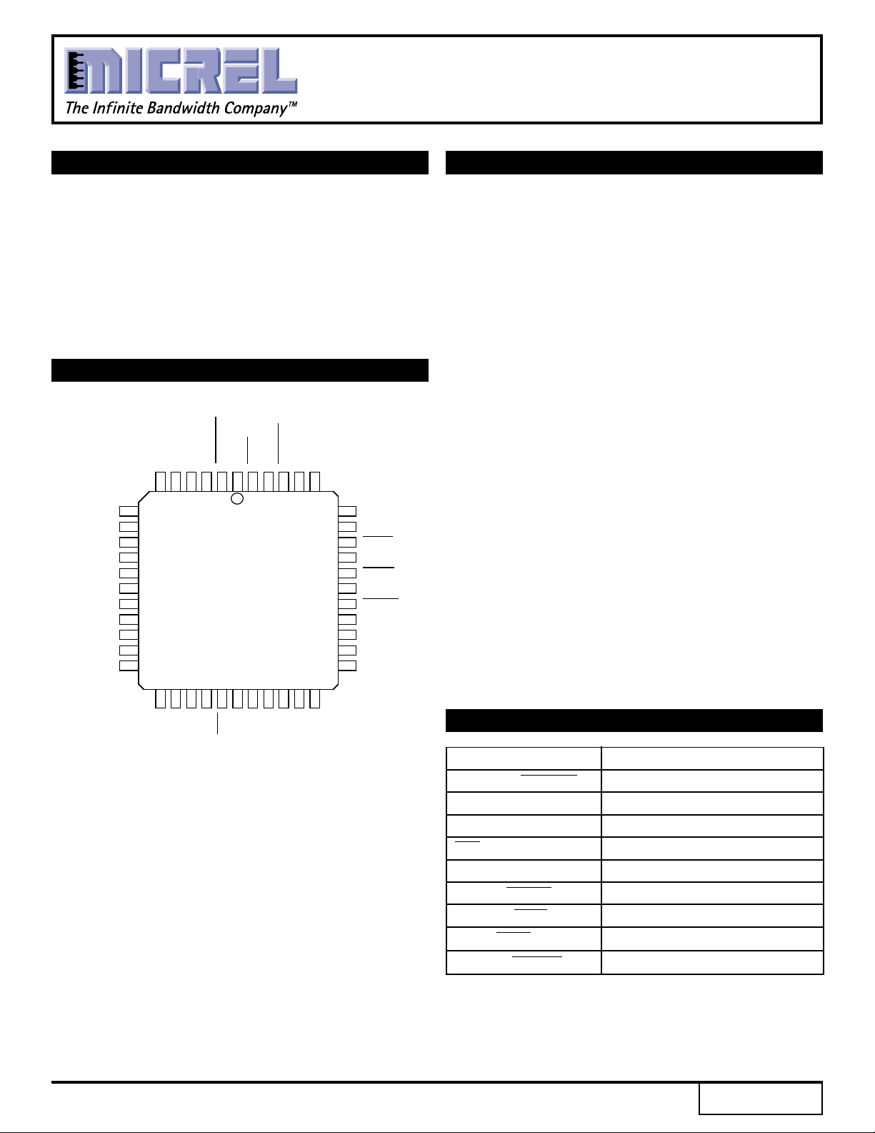
PIN CONFIGURATION
RCLK
RCLKLV
RCLKLV
VEE
39
38
37
36
35
34
33
32
31
30
29
VEE
PCLK1
PCLK1
PCLK2
PCLK2
VCC
USYNC
USYNC
NC
NC
VCC
VEEA
NC
NC
FILP
FILN
VCCA
NC
NC
NC
NC
NC
7
8
9
10
11
12
13
14
15
16
17
VEENCNC
REF_CLK
RCLK
REF_CLK
VCC
1
23456 4443424140
TOP VIEW
MQUAD
M44-1
232221201918 24 25 26 27 28
DESCRIPTION
Micrel-Synergy's SY89801A PLL based clock generator
provides, in a single chip, all the necessary clocks for HewlettPackard's PA-8000 Microprocessor.
Utilizing Micrel-Synergy's advanced PLL technology, the
SY89801A accepts a Positive-ECL (PECL) reference clock
input at 100MHz-132MHz, and provides precisely aligned,
ultra-low-jitter ratios of frequencies necessary for the operation
of the processor. In addition, the SY89801A provides the
"USYNC" synchronizing signals as required by the PA-8000.
The frequency ratios are 1:1, 4:3, 3:2, 5:3 and 2:1.
To facilitate direct interfacing to the PA-8000, the SY89801A
operates across +3.3 volt and -1.9 volt supplies. The processor
clock (PCLK), runway clock (RCLK) , and USYNC outputs are
HSTL-compatible. Additionally, there is a PECL-compatible
runway clock output (RCLKLV). The SY89801A requires only
a simple external series-RC loop filter.
Coupling Micrel-Synergy's advanced PLL technology with
our proprietary ASSET bipolar process has produced a
Timing Generator IC which meets the stringent requirements
of the PA-8000 µP, while setting a new standard for
performance and flexibility.
NCNCNC
VCC
RST
VEE
NC
FSEL1
FSEL0
VCC
FSEL2
PIN NAMES
Pin Function
REF_CLK, REF_CLK Differential Input Ref. Clock
FILP, FILN Filter Pins (Positive & Negative)
VCCA, VEEA Analog VCC, VEE
RST Master Reset
FSEL2-0 LVPECL Frequency Select Pins
USYNC, USYNC Diff. HSTL Sync Signal for PA-8000
PCLK1-2, PCLK1-2 Diff. HSTL Processor Clock Signal
RCLK, RCLK Diff. HSTL Runway Clock Signal
RCLKLV, RCLKLV Diff. LVPECL Clock Signal
Rev.: E Amendment: /0
1
Issue Date: November 1998
Page 2
Micrel
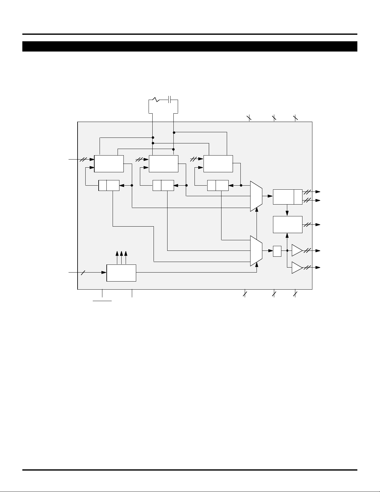
BLOCK DIAGRAM
ClockWorks™
PRELIMINARY
SY89801A
LOOP FILTER
AVCC VCCOVCC
232
REFCLK
(100-132MHz)
(PECL)
FSEL
(PECL)
3
LF VCO
(600-800)
f/2÷ 3
RESET
(PECL)
VCO
ENAB
DECODE
TEST
(PECL)
MF VCO
(800-1060)
f/2÷ 4 f/2÷ 5
HF VCO
(1000-1320)
÷
2/ 3/ 4/ 5
f/2
f/2
SYNC
LOGIC
223
GND DVEE AVEE
PCLK1
(HSTL)
PCLK2
(HSTL)
USYNC
(HSTL)
RCLK
(HSTL)
RCLKLV
(PECL)
2
Page 3

ClockWorks™
PRELIMINARY
Micrel
3.3V DC ELECTRICAL CHARACTERISTICS
VCC = VCCA = 3.3V ±10%; VEEA = VEE = –1.9V
Symbol Parameter Min. Typ. Max. Unit Condition
VCC Power Supply Voltage 3.0 — 3.6 V VEE = –1.9V
CC Power Supply Current (VCC) — 250 321 mA
I
PECL DC ELECTRICAL CHARACTERISTICS
VCC = 3.3V ±10%; VEE = –1.9V
Symbol Parameter Min. Typ. Max. Unit Condition
VOH Output HIGH Voltage VCC – 1.075 — VCC – 0.830 V
VOL Output LOW Voltage VCC – 1.860 — VCC – 1.570 V
VIH Input HIGH Voltage VCC – 1.165 — VCC – 0.880 V
VIL Input LOW Voltage VCC – 1.810 — VCC – 1.475 V
BB PECL Threshold — VCC – 1.35 — V
V
SY89801A
HSTL DC ELECTRICAL CHARACTERISTICS
VCC = 3.3V ±10%; VEE = –1.9V
Symbol Parameter Min. Typ. Max. Unit Condition
VOH Output HIGH Voltage VCC – 2.3 — VCC – 2.1 V
V
OL Output LOW Voltage VCC – 3.1 — VCC – 2.9 V
AC ELECTRICAL CHARACTERISTICS
VCC = 3.3V ±10%; VEE = –1.9V
Symbol Parameter Min. Typ. Max. Min. Typ. Max. Min. Typ. Max. Unit Condition
fVCO Maximum VCO Frequency 1320 — — 1320 — — 1320 — — MHz
MAX Maximum PCLK Output Frequency 264 — — 264 — — 264 — — MHz
f
Maximum RCLK Output Frequency 132 — — 132 — — 132 — — MHz
(2)
skew
t
tpe Phase Error — — ±250 — — ±250 — — ±250 ps
(2)
tj
tdc
tr Rise/Fall Times 100 — 800 100 — 800 100 — 800 ps
(2)
tf (20% to 80%)
NOTES:
1. All HSTL outputs terminated into 50 ohms in parallel with 3pf to GND.
2. tskew, tj, tdc, tr and tf are specified by HP for the PA-8000. This is our best information as of the date of this document.
PCLK to PCLK — — ±50 — — ±50 — — ±50 ps Measured at
RCLK to RCLKLV — — ±100 — — ±100 — — ±100 ps differential
PCLK to RCLK — — ±100 — — ±100 — — ±100 ps crossover
PCLK (neg.) to USYNC — — ±500 — — ±500 — — ±500 ps
RCLK to REF_CLK
Output Jitter –50 — +50 –50 — +50 –50 — +50 ps Peak to Peak,
(2)
Output Duty Cycle 49 — 51 49 — 51 49 — 51 %
(1)
TA = 0°CTA = +25°CTA = +70°C
Cycle to Cycle
3
Page 4

Micrel
APPLICATIONS INFORMATION
ClockWorks™
PRELIMINARY
SY89801A
The following table lists the various PCLK and RCLK
ratios supported by the SY89801A and the corresponding
PCLK, RCLK, FB and VCO frequencies. The table is
arranged in order of increasing PCLK:RCLK ratio. The
table was designed to balance several constraints:
FSEL <2:0> PCLK:RCLK fPCLK (MHz) fRCLK (MHz) VCO/P:VCO/R fVCO (MHz)
000 1:1 100-132 100-132 8:8 800-1056
001 4:3 133.3-176 100-132 6:8 800-1056
010 3:2 150-198 100-132 4:6 600-792
011 5:3 166.7-220 100-132 6:10 1000-1320
100 2:1 200-264 100-132 4:8 800-1056
101 1:1 100-132 100-132 6:6 600-792
110 1:1 100-132 100-132 10:10 1000-1320
111 n/a n/a n/a n/a n/a
■ 2.5:1 VCO frequency range
■ Maximum system frequency of 120MHz plus 10%
margin
■ Maximum output frequency of 264MHz
VCO ÷ ratios
LOOP FILTER COMPONENT SELECTION
filp filn
PRODUCT ORDERING CODE
Ordering Package Operating
Code Type Range
SY89801AMC M44-1 Commercial
SY89801AMCA
NOTES:
1. "A" denotes enhanced 200MHz testing.
(1)
M44-1 Commercial
R
R = 500Ω ±10%
C1 = 1000pF ±10%
C1
4
Page 5

Micrel
44 LEAD MLCC (M44-1)
ClockWorks™
PRELIMINARY
SY89801A
Rev. 02
MICREL-SYNERGY 3250 SCOTT BOULEVARD SANTA CLARA CA 95054 USA
TEL + 1 (408) 980-9191 FAX + 1 (408) 914-7878 WEB http://www.micrel.com
This information is believed to be accurate and reliable, however no responsibility is assumed by Micrel for its use nor for any infringement of patents or
other rights of third parties resulting from its use. No license is granted by implication or otherwise under any patent or patent right of Micrel Inc.
© 2000 Micrel Incorporated
5
 Loading...