

Daikin ERGA04DAV3, ERGA06DAV3, ERGA08DAV3, EHVH04S23DAV, EHVH08S23DAV User reference guide
...Page 1
Installer reference guide
Daikin Altherma – Low temperature split
ERGA04DAV3(A)
ERGA06DAV3(A)
ERGA08DAV3(A)
EHVH04S23DAV(G)
EHVH08S23DAV(G)
Installer reference guide
Daikin Altherma – Low temperature split
English
Page 2

Table of contents
Table of contents
1 General safety precautions 3
1.1 About the documentation .......................................................... 3
1.1.1 Meaning of warnings and symbols.............................. 3
1.2 For the installer.......................................................................... 4
1.2.1 General ....................................................................... 4
1.2.2 Installation site ............................................................ 4
1.2.3 Refrigerant .................................................................. 4
1.2.4 Brine............................................................................ 5
1.2.5 Water .......................................................................... 5
1.2.6 Electrical ..................................................................... 6
2 About the documentation 6
2.1 About this document.................................................................. 6
2.2 Installer reference guide at a glance ......................................... 7
3 About the box 7
3.1 Overview: About the box ........................................................... 7
3.2 Outdoor unit............................................................................... 7
3.2.1 To unpack the outdoor unit ......................................... 7
3.2.2 To handle the outdoor unit.......................................... 7
3.2.3 To remove the accessories from the outdoor unit....... 8
3.3 Indoor unit ................................................................................. 8
3.3.1 To unpack the indoor unit ........................................... 8
3.3.2 To remove the accessories from the indoor unit......... 8
3.3.3 To handle the indoor unit ............................................ 8
4 About the units and options 9
4.1 Overview: About the units and options...................................... 9
4.2 Identification .............................................................................. 9
4.2.1 Identification label: Outdoor unit ................................. 9
4.2.2 Identification label: Indoor unit .................................... 9
4.3 Combining units and options ..................................................... 9
4.3.1 Possible options for the outdoor unit........................... 9
4.3.2 Possible options for the indoor unit............................. 9
4.3.3 Possible combinations of indoor unit and outdoor
unit .............................................................................. 10
5 Application guidelines 10
5.1 Overview: Application guidelines............................................... 10
5.2 Setting up the space heating system ........................................ 11
5.2.1 Single room................................................................. 11
5.2.2 Multiple rooms – OneLWT zone ................................ 12
5.2.3 Multiple rooms – TwoLWT zones............................... 14
5.3 Setting up an auxiliary heat source for space heating............... 15
5.4 Setting up the domestic hot water tank ..................................... 16
5.4.1 System layout – Integrated DHW tank........................ 16
5.4.2 Selecting the volume and desired temperature for
the DHW tank.............................................................. 16
5.4.3 Setup and configuration – DHW tank.......................... 17
5.4.4 DHW pump for instant hot water................................. 17
5.4.5 DHW pump for disinfection ......................................... 17
5.5 Setting up the energy metering ................................................. 18
5.5.1 Produced heat............................................................. 18
5.5.2 Consumed energy....................................................... 18
5.5.3 Normal kWh rate power supply................................... 18
5.5.4 Preferential kWh rate power supply............................ 19
5.6 Setting up the power consumption control ................................ 19
5.6.1 Permanent power limitation ........................................ 19
5.6.2 Power limitation activated by digital inputs ................. 20
5.6.3 Power limitation process ............................................. 20
5.7 Setting up an external temperature sensor ............................... 21
6 Preparation 21
6.1 Overview: Preparation............................................................... 21
6.2 Preparing the installation site .................................................... 21
6.2.1 Installation site requirements of the outdoor unit ........ 21
6.2.2 Additional installation site requirements of the
outdoor unit in cold climates ........................................ 22
6.2.3 Installation site requirements of the indoor unit ........... 23
6.3 Preparing refrigerant piping........................................................ 25
6.3.1 Refrigerant piping requirements................................... 25
6.3.2 Refrigerant piping insulation ........................................ 25
6.4 Preparing water piping ............................................................... 25
6.4.1 Water circuit requirements ........................................... 25
6.4.2 Formula to calculate the expansion vessel pre-
pressure ....................................................................... 26
6.4.3 To check the water volume and flow rate .................... 26
6.4.4 Changing the pre-pressure of the expansion vessel.... 27
6.4.5 To check the water volume: Examples ........................ 28
6.5 Preparing electrical wiring .......................................................... 28
6.5.1 About preparing electrical wiring.................................. 28
6.5.2 About preferential kWh rate power supply ................... 28
6.5.3 Overview of electrical connections except external
actuators ...................................................................... 29
6.5.4 Overview of electrical connections for external and
internal actuators ......................................................... 29
7 Installation 29
7.1 Overview: Installation ................................................................. 29
7.2 Opening the units ....................................................................... 30
7.2.1 About opening the units ............................................... 30
7.2.2 To open the outdoor unit.............................................. 30
7.2.3 To open the indoor unit ................................................ 30
7.2.4 To open the switch box cover of the indoor unit .......... 30
7.2.5 To lower the switch box on the indoor unit................... 31
7.3 Mounting the outdoor unit........................................................... 31
7.3.1 About mounting the outdoor unit.................................. 31
7.3.2 Precautions when mounting the outdoor unit............... 31
7.3.3 To provide the installation structure ............................. 31
7.3.4 To install the outdoor unit............................................. 32
7.3.5 To provide drainage ..................................................... 33
7.3.6 To prevent the outdoor unit from falling over ............... 34
7.4 Mounting the indoor unit............................................................. 34
7.4.1 About mounting the indoor unit.................................... 34
7.4.2 Precautions when mounting the indoor unit................. 34
7.4.3 To install the indoor unit............................................... 34
7.4.4 To connect the drain hose to the drain ........................ 34
7.5 Connecting the refrigerant piping ............................................... 35
7.5.1 About connecting the refrigerant piping ....................... 35
7.5.2 Precautions when connecting the refrigerant piping.... 35
7.5.3 Guidelines when connecting the refrigerant piping...... 36
7.5.4 Pipe bending guidelines............................................... 36
7.5.5 To flare the pipe end .................................................... 36
7.5.6 To braze the pipe end .................................................. 36
7.5.7 Using the stop valve and service port .......................... 36
7.5.8 To connect the refrigerant piping to the outdoor unit ... 37
7.5.9 To connect the refrigerant piping to the indoor unit ..... 37
7.6 Checking the refrigerant piping .................................................. 38
7.6.1 About checking the refrigerant piping .......................... 38
7.6.2 Precautions when checking the refrigerant piping ....... 38
7.6.3 To check for leaks........................................................ 38
7.6.4 To perform vacuum drying ........................................... 38
7.7 Charging refrigerant ................................................................... 39
7.7.1 About charging refrigerant ........................................... 39
7.7.2 Precautions when charging refrigerant ........................ 39
7.7.3 To determine the additional refrigerant amount........... 39
7.7.4 To determine the complete recharge amount.............. 39
7.7.5 To charge additional refrigerant ................................... 39
7.7.6 To fix the fluorinated greenhouse gases label ............. 39
7.8 Connecting the water piping....................................................... 40
7.8.1 About connecting the water piping............................... 40
7.8.2 Precautions when connecting the water piping............ 40
7.8.3 To connect the water piping......................................... 40
7.8.4 To connect the recirculation piping .............................. 41
7.8.5 To fill the water circuit .................................................. 41
7.8.6 To fill the domestic hot water tank ............................... 41
Installer reference guide
2
ERGA04~08DAV3(A) + EHVH04+08S23DAV
Daikin Altherma – Low temperature split
4P499573-1A – 2018.11
Page 3
1 General safety precautions
7.8.7 To insulate the water piping........................................ 41
7.9 Connecting the electrical wiring................................................. 41
7.9.1 About connecting the electrical wiring......................... 41
7.9.2 About electrical compliance ........................................ 41
7.9.3 Precautions when connecting the electrical wiring ..... 41
7.9.4 Guidelines when connecting the electrical wiring ....... 42
7.9.5 Specifications of standard wiring components............ 42
7.9.6 To connect the electrical wiring on the outdoor unit.... 42
7.9.7 To connect the electrical wiring on the indoor unit...... 43
7.9.8 To connect the main power supply ............................. 44
7.9.9 To connect the shut-off valve...................................... 44
7.9.10 To connect the electrical meters ................................. 44
7.9.11 To connect the domestic hot water pump ................... 44
7.9.12 To connect the alarm output ....................................... 44
7.9.13 To connect the space heating ON/OFF output ........... 45
7.9.14 To connect the changeover to external heat source ... 45
7.9.15 To connect the power consumption digital inputs ....... 45
7.9.16 To connect the safety thermostat (normal closed
contact) ....................................................................... 45
7.9.17 To connect the anti-legionella heater power supply.... 46
7.10 Finishing the outdoor unit installation ........................................ 46
7.10.1 To finish the outdoor unit installation .......................... 46
7.11 Finishing the indoor unit installation .......................................... 46
7.11.1 To close the indoor unit............................................... 46
8 Configuration 47
8.1 Overview: Configuration ............................................................ 47
8.1.1 To access the most used commands ......................... 47
8.2 Configuration wizard.................................................................. 48
8.3 Possible screens ....................................................................... 48
8.3.1 Possible screens: Overview........................................ 48
8.3.2 Home screen............................................................... 48
8.3.3 Main menu screen ...................................................... 49
8.3.4 Menu screen ............................................................... 49
8.3.5 Setpoint screen........................................................... 49
8.3.6 Detailed screen with values ........................................ 50
8.3.7 Detailed screen with weather-dependent curve.......... 50
8.3.8 Schedule screen: Example ......................................... 50
8.4 Settings menu ........................................................................... 52
8.4.1 Malfunction.................................................................. 52
8.4.2 Room .......................................................................... 52
8.4.3 Main zone ................................................................... 53
8.4.4 Additional zone ........................................................... 56
8.4.5 Space heating............................................................. 57
8.4.6 Tank ............................................................................ 60
8.4.7 User settings ............................................................... 63
8.4.8 Information .................................................................. 64
8.4.9 Installer settings .......................................................... 65
8.5 Menu structure: Overview user settings .................................... 73
8.6 Menu structure: Overview installer settings............................... 74
11.5.1 To remove the water filter ............................................ 80
11.5.2 To clean the water filter in case of trouble ................... 81
11.5.3 To install the water filter ............................................... 81
12 Troubleshooting 81
12.1 Overview: Troubleshooting......................................................... 81
12.2 Precautions when troubleshooting ............................................. 82
12.3 Solving problems based on symptoms....................................... 82
12.3.1 Symptom: The unit is NOT heating as expected ......... 82
12.3.2 Symptom: The compressor does NOT start (space
heating or domestic water heating).............................. 82
12.3.3 Symptom: The system is making gurgling noises
after commissioning ..................................................... 83
12.3.4 Symptom: The pump is making noise (cavitation) ....... 83
12.3.5 Symptom: The pressure relief valve opens.................. 83
12.3.6 Symptom: The water pressure relief valve leaks ......... 84
12.3.7 Symptom: The space is NOT sufficiently heated at
low outdoor temperatures ............................................ 84
12.3.8 Symptom: The pressure at the tapping point is
temporarily unusually high ........................................... 84
12.3.9 Symptom: Decoration panels are pushed away due
to a swollen tank .......................................................... 84
12.3.10 Symptom: Tank disinfection function is NOT
completed correctly (AH-error)..................................... 84
12.4 Solving problems based on error codes ..................................... 85
12.4.1 To display the help text in case of a malfunction ......... 85
12.4.2 Error codes: Overview ................................................. 85
13 Disposal 86
13.1 Overview: Disposal..................................................................... 86
13.2 To pump down............................................................................ 86
13.3 To start and stop forced cooling ................................................. 87
14 Technical data 88
14.1 Piping diagram: Outdoor unit...................................................... 88
14.2 Piping diagram: Indoor unit ........................................................ 89
14.3 Wiring diagram: Outdoor unit ..................................................... 90
14.4 Wiring diagram: Indoor unit ........................................................ 91
14.5 Table 1 – Maximum refrigerant charge allowed in a room:
indoor unit................................................................................... 94
14.6 Table 2 – Minimum floor area: indoor unit .................................. 94
14.7 Table 3 – Minimum venting opening area for natural
ventilation: indoor unit ................................................................ 94
14.8 ESP curve: Indoor unit ............................................................... 95
15 Glossary 95
16 Field settings table 96
1 General safety precautions
9 Commissioning 75
9.1 Overview: Commissioning......................................................... 75
9.2 Precautions when commissioning ............................................. 75
9.3 Checklist before commissioning................................................ 75
9.4 Checklist during commissioning ................................................ 75
9.4.1 To check the minimum flow rate ................................. 76
9.4.2 Air purge function........................................................ 76
9.4.3 To perform an operation test run ................................ 76
9.4.4 To perform an actuator test run .................................. 77
9.4.5 Underfloor heating screed dryout................................ 77
10 Hand-over to the user 78
11 Maintenance and service 78
11.1 Overview: Maintenance and service ......................................... 78
11.2 Maintenance safety precautions................................................ 78
11.3 Checklist for yearly maintenance of the outdoor unit ................ 79
11.4 Checklist for yearly maintenance of the indoor unit................... 79
11.4.1 To drain the domestic hot water tank .......................... 80
11.5 About cleaning the water filter in case of trouble....................... 80
ERGA04~08DAV3(A) + EHVH04+08S23DAV
Daikin Altherma – Low temperature split
4P499573-1A – 2018.11
1.1 About the documentation
▪ The original documentation is written in English. All other
languages are translations.
▪ The precautions described in this document cover very important
topics, follow them carefully.
▪ The installation of the system, and all activities described in the
installation manual and the installer reference guide MUST be
performed by an authorised installer.
1.1.1 Meaning of warnings and symbols
DANGER
Indicates a situation that results in death or serious injury.
DANGER: RISK OF ELECTROCUTION
Indicates a situation that could result in electrocution.
Installer reference guide
3
Page 4
1 General safety precautions
DANGER: RISK OF BURNING
Indicates a situation that could result in burning because of
extreme hot or cold temperatures.
DANGER: RISK OF EXPLOSION
Indicates a situation that could result in explosion.
WARNING
Indicates a situation that could result in death or serious
injury.
WARNING: FLAMMABLE MATERIAL
CAUTION
Indicates a situation that could result in minor or moderate
injury.
NOTICE
Indicates a situation that could result in equipment or
property damage.
INFORMATION
Indicates useful tips or additional information.
Symbol Explanation
Before installation, read the installation and
operation manual, and the wiring instruction sheet.
Before performing maintenance and service tasks,
read the service manual.
For more information, see the installer and user
reference guide.
1.2 For the installer
1.2.1 General
If you are NOT sure how to install or operate the unit, contact your
dealer.
NOTICE
Improper installation or attachment of equipment or
accessories could result in electric shock, short-circuit,
leaks, fire or other damage to the equipment. Only use
accessories, optional equipment and spare parts made or
approved by Daikin.
WARNING
Make sure installation, testing and applied materials
comply with applicable legislation (on top of the
instructions described in the Daikin documentation).
CAUTION
Wear adequate personal protective equipment (protective
gloves, safety glasses,…) when installing, maintaining or
servicing the system.
WARNING
Tear apart and throw away plastic packaging bags so that
nobody, especially children, can play with them. Possible
risk: suffocation.
DANGER: RISK OF BURNING
▪ Do NOT touch the refrigerant piping, water piping or
internal parts during and immediately after operation. It
could be too hot or too cold. Give it time to return to
normal temperature. If you must touch it, wear
protective gloves.
▪ Do NOT touch any accidental leaking refrigerant.
WARNING
Provide adequate measures to prevent that the unit can be
used as a shelter by small animals. Small animals that
make contact with electrical parts can cause malfunctions,
smoke or fire.
CAUTION
Do NOT touch the air inlet or aluminium fins of the unit.
NOTICE
▪ Do NOT place any objects or equipment on top of the
unit.
▪ Do NOT sit, climb or stand on the unit.
NOTICE
Works executed on the outdoor unit are best done under
dry weather conditions to avoid water ingress.
In accordance with the applicable legislation, it might be necessary
to provide a logbook with the product containing at least: information
on maintenance, repair work, results of tests, stand-by periods,…
Also, at least, following information MUST be provided at an
accessible place at the product:
▪ Instructions for shutting down the system in case of an emergency
▪ Name and address of fire department, police and hospital
▪ Name, address and day and night telephone numbers for
obtaining service
In Europe, EN378 provides the necessary guidance for this logbook.
1.2.2 Installation site
▪ Provide sufficient space around the unit for servicing and air
circulation.
▪ Make sure the installation site withstands the unit's weight and
vibration.
▪ Make sure the area is well ventilated. Do NOT block any
ventilation openings.
▪ Make sure the unit is level.
Do NOT install the unit in the following places:
▪ In potentially explosive atmospheres.
▪ In places where there is machinery that emits electromagnetic
waves. Electromagnetic waves may disturb the control system,
and cause malfunction of the equipment.
▪ In places where there is a risk of fire due to the leakage of
flammable gases (example: thinner or gasoline), carbon fibre,
ignitable dust.
▪ In places where corrosive gas (example: sulphurous acid gas) is
produced. Corrosion of copper pipes or soldered parts may cause
the refrigerant to leak.
Installer reference guide
4
1.2.3 Refrigerant
If applicable. See the installation manual or installer reference guide
of your application for more information.
ERGA04~08DAV3(A) + EHVH04+08S23DAV
Daikin Altherma – Low temperature split
4P499573-1A – 2018.11
Page 5
1 General safety precautions
NOTICE
Make sure refrigerant piping installation complies with
applicable legislation. In Europe, EN378 is the applicable
standard.
NOTICE
Make sure the field piping and connections are NOT
subjected to stress.
WARNING
During tests, NEVER pressurize the product with a
pressure higher than the maximum allowable pressure (as
indicated on the nameplate of the unit).
WARNING
Take sufficient precautions in case of refrigerant leakage. If
refrigerant gas leaks, ventilate the area immediately.
Possible risks:
▪ Excessive refrigerant concentrations in a closed room
can lead to oxygen deficiency.
▪ Toxic gas may be produced if refrigerant gas comes
into contact with fire.
DANGER: RISK OF EXPLOSION
Pump down – Refrigerant leakage. If you want to pump
down the system, and there is a leak in the refrigerant
circuit:
▪ Do NOT use the unit's automatic pump down function,
with which you can collect all refrigerant from the
system into the outdoor unit. Possible consequence:
Self-combustion and explosion of the compressor
because of air going into the operating compressor.
▪ Use a separate recovery system so that the unit's
compressor does NOT have to operate.
WARNING
ALWAYS recover the refrigerant. Do NOT release them
directly into the environment. Use a vacuum pump to
evacuate the installation.
NOTICE
After all the piping has been connected, make sure there is
no gas leak. Use nitrogen to perform a gas leak detection.
NOTICE
▪ To avoid compressor breakdown, do NOT charge more
than the specified amount of refrigerant.
▪ When the refrigerant system is to be opened,
refrigerant MUST be treated according to the applicable
legislation.
WARNING
Make sure there is no oxygen in the system. Refrigerant
may only be charged after performing the leak test and the
vacuum drying.
▪ In case re-charge is required, refer to the nameplate of the unit. It
states the type of refrigerant and necessary amount.
▪ The unit is factory charged with refrigerant and depending on pipe
sizes and pipe lengths some systems require additional charging
of refrigerant.
▪ Only use tools exclusively for the refrigerant type used in the
system, this to ensure pressure resistance and prevent foreign
materials from entering into the system.
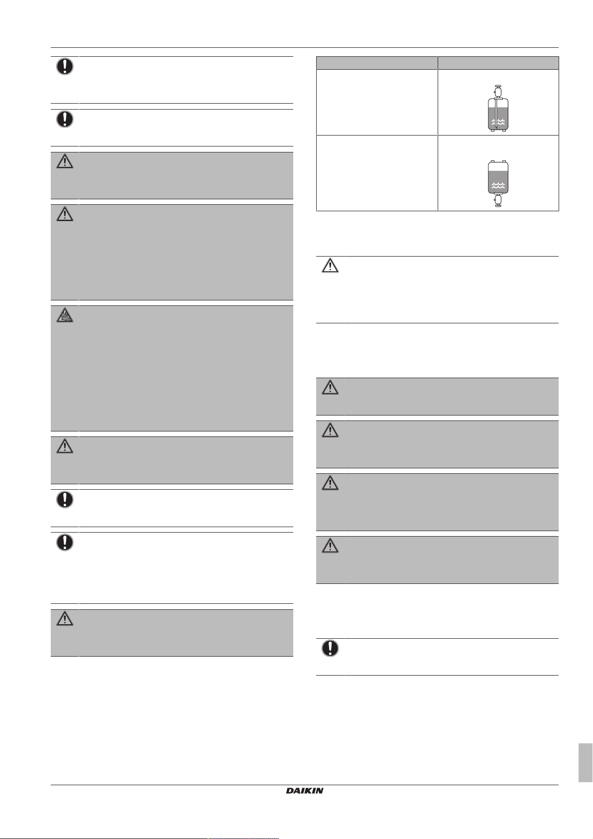
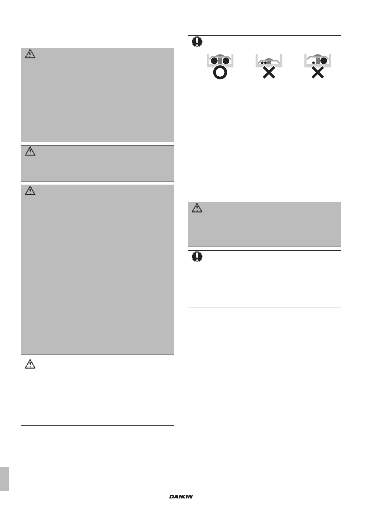
▪ Charge the liquid refrigerant as follows:
If Then
A siphon tube is present
(i.e., the cylinder is marked with
"Liquid filling siphon attached")
A siphon tube is NOT present Charge with the cylinder upside
▪ Open refrigerant cylinders slowly.
▪ Charge the refrigerant in liquid form. Adding it in gas form may
prevent normal operation.
CAUTION
When the refrigerant charging procedure is done or when
pausing, close the valve of the refrigerant tank
immediately. If the valve is NOT closed immediately,
remaining pressure might charge additional refrigerant.
Possible consequence: Incorrect refrigerant amount.
Charge with the cylinder upright.
down.
1.2.4 Brine
If applicable. See the installation manual or installer reference guide
of your application for more information.
WARNING
The selection of the brine MUST be in accordance with the
applicable legislation.
WARNING
Take sufficient precautions in case of brine leakage. If
brine leaks, ventilate the area immediately and contact
your local dealer.
WARNING
The ambient temperature inside the unit can get much
higher than that of the room, e.g. 70°C. In case of a brine
leak, hot parts inside the unit can create a hazardous
situation.
WARNING
The use and installation of the application MUST comply
with the safety and environmental precautions specified in
the applicable legislation.
1.2.5 Water
If applicable. See the installation manual or installer reference guide
of your application for more information.
NOTICE
Make sure water quality complies with EU directive
98/83EC.
ERGA04~08DAV3(A) + EHVH04+08S23DAV
Daikin Altherma – Low temperature split
4P499573-1A – 2018.11
Installer reference guide
5
Page 6
2 About the documentation
1.2.6 Electrical
DANGER: RISK OF ELECTROCUTION
▪ Turn OFF all power supply before removing the
switch box cover, connecting electrical wiring or
touching electrical parts.
▪ Disconnect the power supply for more than 1 minute,
and measure the voltage at the terminals of main circuit
capacitors or electrical components before servicing.
The voltage MUST be less than 50 V DC before you
can touch electrical components. For the location of the
terminals, see the wiring diagram.
▪ Do NOT touch electrical components with wet hands.
▪ Do NOT leave the unit unattended when the service
cover is removed.
WARNING
If NOT factory installed, a main switch or other means for
disconnection, having a contact separation in all poles
providing full disconnection under overvoltage category III
condition, MUST be installed in the fixed wiring.
WARNING
▪ ONLY use copper wires.
▪ Make sure the field wiring complies with the applicable
legislation.
▪ All field wiring MUST be performed in accordance with
the wiring diagram supplied with the product.
▪ NEVER squeeze bundled cables and make sure they
do NOT come in contact with the piping and sharp
edges. Make sure no external pressure is applied to the
terminal connections.
▪ Make sure to install earth wiring. Do NOT earth the unit
to a utility pipe, surge absorber, or telephone earth.
Incomplete earth may cause electrical shock.
▪ Make sure to use a dedicated power circuit. NEVER
use a power supply shared by another appliance.
▪ Make sure to install the required fuses or circuit
breakers.
▪ Make sure to install an earth leakage protector. Failure
to do so may cause electric shock or fire.
▪ When installing the earth leakage protector, make sure
it is compatible with the inverter (resistant to high
frequency electric noise) to avoid unnecessary opening
of the earth leakage protector.
CAUTION
When connecting the power supply, the earth connection
must be made before the current-carrying connections are
established. When disconnecting the power supply, the
current-carrying connections must be separated before the
earth connection is. The length of the conductors between
the power supply stress relief and the terminal block itself
must be as such that the current-carrying wires are
tautened before the earth wire is in case the power supply
is pulled loose from the stress relief.
NOTICE
Precautions when laying power wiring:
▪ Do NOT connect wiring of different thicknesses to the
power terminal block (slack in the power wiring may
cause abnormal heat).
▪ When connecting wiring which is the same thickness,
do as shown in the figure above.
▪ For wiring, use the designated power wire and connect
firmly, then secure to prevent outside pressure being
exerted on the terminal board.
▪ Use an appropriate screwdriver for tightening the
terminal screws. A screwdriver with a small head will
damage the head and make proper tightening
impossible.
▪ Over-tightening the terminal screws may break them.
Install power cables at least 1 metre away from televisions or radios
to prevent interference. Depending on the radio waves, a distance of
1metre may not be sufficient.
WARNING
▪ After finishing the electrical work, confirm that each
electrical component and terminal inside the electrical
components box is connected securely.
▪ Make sure all covers are closed before starting up the
unit.
NOTICE
Only applicable if the power supply is three‑phase, and the
compressor has an ON/OFF starting method.
If there exists the possibility of reversed phase after a
momentary black out and the power goes on and off while
the product is operating, attach a reversed phase
protection circuit locally. Running the product in reversed
phase can break the compressor and other parts.
2 About the documentation
2.1 About this document
Target audience
Authorised installers
Documentation set
This document is part of a documentation set. The complete set
consists of:
▪ General safety precautions:
▪ Safety instructions that you must read before installing
▪ Format: Paper (in the box of the indoor unit)
▪ Indoor unit installation manual:
▪ Installation instructions
▪ Format: Paper (in the box of the indoor unit)
▪ Outdoor unit installation manual:
▪ Installation instructions
▪ Format: Paper (in the box of the outdoor unit)
Installer reference guide
6
ERGA04~08DAV3(A) + EHVH04+08S23DAV
Daikin Altherma – Low temperature split
4P499573-1A – 2018.11
Page 7
3 About the box
1 2
▪ Installer reference guide:
▪ Preparation of the installation, good practices, reference data,…
▪ Format: Digital files on http://www.daikineurope.com/support-
and-manuals/product-information/
▪ Addendum book for optional equipment:
▪ Additional info about how to install optional equipment
▪ Format: Paper (in the box of the indoor unit) + Digital files on
http://www.daikineurope.com/support-and-manuals/productinformation/
Latest revisions of the supplied documentation may be available on
the regional Daikin website or via your dealer.
The original documentation is written in English. All other languages
are translations.
Technical engineering data
▪ A subset of the latest technical data is available on the regional
Daikin website (publicly accessible).
▪ The full set of latest technical data is available on the Daikin
extranet (authentication required).
2.2 Installer reference guide at a glance
Chapter Description
General safety
precautions
About the documentation What documentation exists for the
About the box How to unpack the units and remove
About the units and
options
Application guidelines Various installation setups of the system
Preparation What to do and know before going
Installation What to do and know to install the
Configuration What to do and know to configure the
Commissioning What to do and know to commission the
Hand‑over to the user What to give and explain to the user
Maintenance and service How to maintain and service the units
Troubleshooting What to do in case of problems
Disposal How to dispose of the system
Technical data Specifications of the system
Glossary Definition of terms
Field settings table Table to be filled in by the installer, and
Safety instructions that you must read
before installing
installer
their accessories
▪ How to identify the units
▪ Possible combinations of units and
options
on‑site
system
system after it is installed
system after it is configured
kept for future reference
Note: There is also an installer settings
table in the user reference guide. This
table has to be filled in by the installer
and handed over to the user.
3 About the box
3.1 Overview: About the box
This chapter describes what you have to do after the boxes with the
outdoor and indoor unit are delivered on-site.
Keep the following in mind:
▪ At delivery, the unit MUST be checked for damage. Any damage
MUST be reported immediately to the carrier's claims agent.
▪ Bring the packed unit as close as possible to its final installation
position to prevent damage during transport.
▪ Prepare the path along which you want to bring the unit inside in
advance.
3.2 Outdoor unit
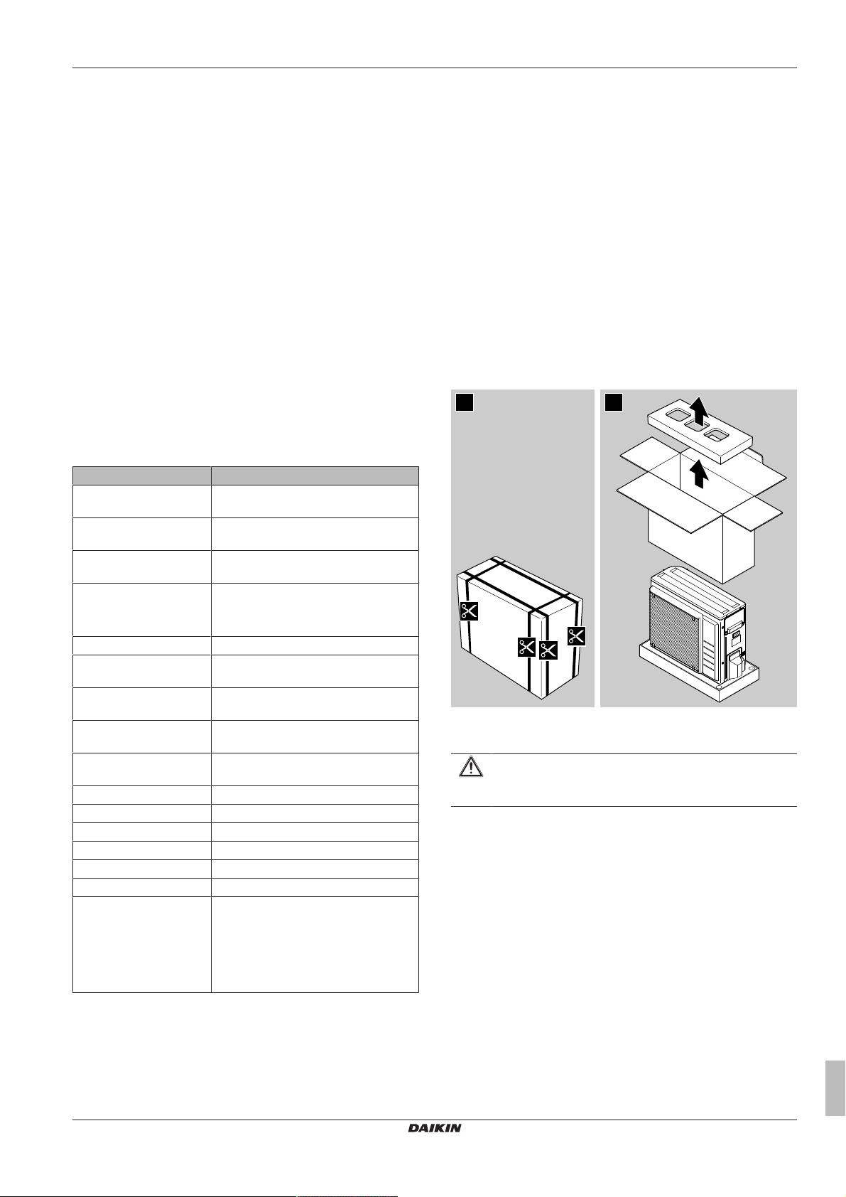
3.2.1 To unpack the outdoor unit
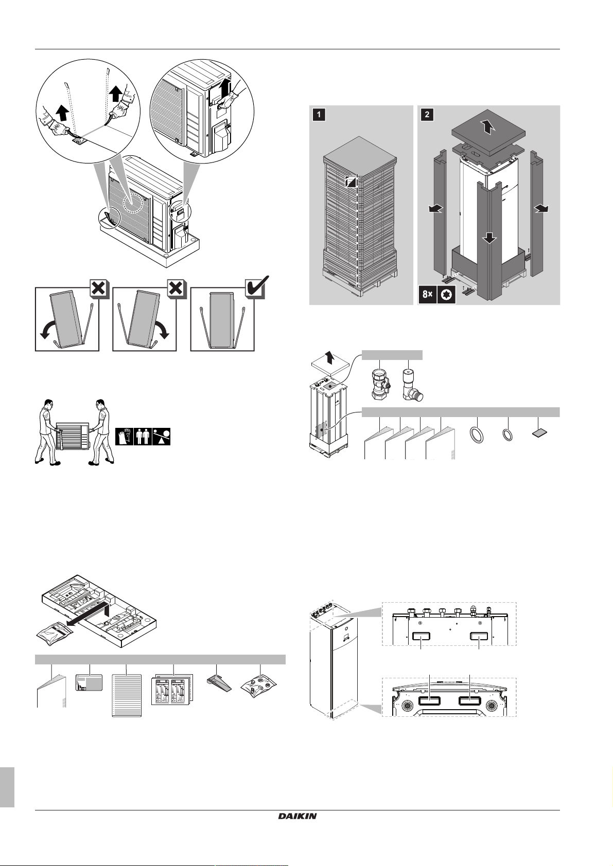
3.2.2 To handle the outdoor unit
CAUTION
To avoid injury, do NOT touch the air inlet or aluminium
fins of the unit.
1 Handle the unit using the sling to the left and the handle to the
right. Pull up both sides of the sling at the same time to prevent
disconnection of the sling from the unit.
ERGA04~08DAV3(A) + EHVH04+08S23DAV
Daikin Altherma – Low temperature split
4P499573-1A – 2018.11
Installer reference guide
7
Page 8
3 About the box
2
1
1
ENERG
IJAY
IAIE
ENERG
IJAY
IAIE
1×1× 1× 1× 2× 1×
da b c e f
1 2
8×
2×
4×
1×
4× 1×
1× 1× 1× 1×
a b
g h ic d e f
b
a a
b
3.3 Indoor unit
3.3.1 To unpack the indoor unit
3.3.2 To remove the accessories from the indoor unit
2 While handling the unit:
▪ Keep both sides of the sling level.
▪ Keep your back straight.
3 After mounting the unit, remove the sling from the unit by pulling
1 side of the sling.
3.2.3 To remove the accessories from the outdoor unit
1 Lift the outdoor unit. See "3.2.2 To handle the outdoor unit"on
page7.
2 Remove the accessories at the bottom of the package.
a Shut-off valves for water circuit
b Overpressure bypass valve
c General safety precautions
d Addendum book for optional equipment
e Indoor unit installation manual
f Operation manual
g Sealing rings for shut-off valves (space heating water
circuit)
h Sealing rings for field-supplied shut-off valves (domestic
hot water circuit)
i Sealing tape for low voltage wiring intake
3.3.3 To handle the indoor unit
Use the handles at the back and at the bottom to carry the unit.
a Outdoor unit installation manual
b Fluorinated greenhouse gases label
c Multilingual fluorinated greenhouse gases label
d Energy label
e Unit mounting plate
f Bolts, nuts, washers, spring washers and wire clamp
Installer reference guide
8
a Handles at the back of the unit
b Handles at the bottom of the unit. Carefully tilt the unit to
the back so that the handles become visible.
ERGA04~08DAV3(A) + EHVH04+08S23DAV
Daikin Altherma – Low temperature split
4P499573-1A – 2018.11
Page 9
4 About the units and options
4 About the units and options
4.1 Overview: About the units and options
This chapter contains information about:
▪ Identifying the outdoor unit
▪ Identifying the indoor unit
▪ Combining the outdoor unit with options
▪ Combining the indoor unit with options
4.2 Identification
NOTICE
When installing or servicing several units at the same time,
make sure NOT to switch the service panels between
different models.
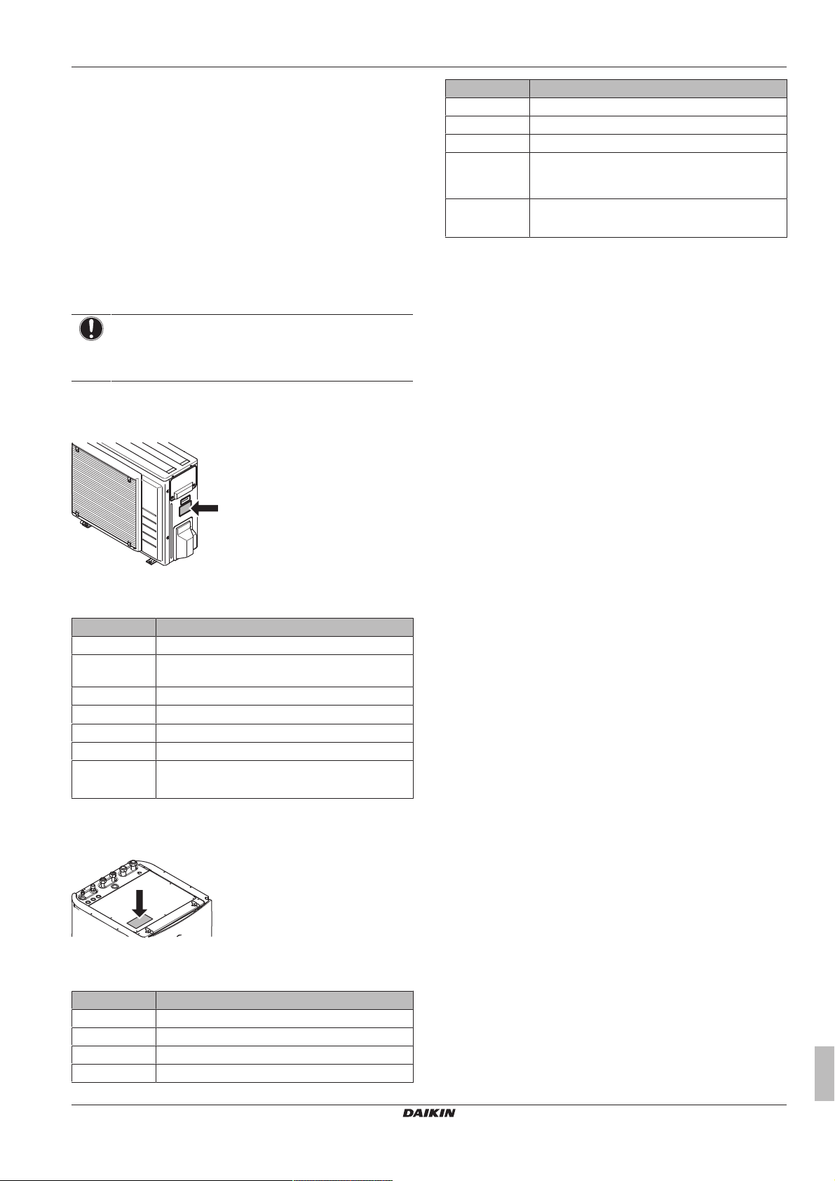
4.2.1 Identification label: Outdoor unit
Location
Model identification
Example: ERGA06DAV3 A
Code Explanation
ER European split outdoor pair heat pump
G Medium water temperature – ambient zone: −10~
−20°C
A Refrigerant R32
06 Capacity class
DA Model series
V3 Power supply
A A=Austrian model
[—]=Non-Austrian model
4.2.2 Identification label: Indoor unit
Location
Code Description
S Integrated tank material: Stainless steel
23 Integrated tank volume
DA Model series
V Model with single phase anti-legionella heater in
the domestic hot water tank. (Without backup
heater in the space heating circuit.)
G G=Grey model
[—]=White model
4.3 Combining units and options
4.3.1 Possible options for the outdoor unit
Drain pan kit (EKDP008D)
The drain pan kit is required to gather the drain from the outdoor
unit. The drain pan kit consists of:
▪ Drain pan
▪ Installation brackets
For installation instructions, see the installation manual of the drain
pan.
Drain pan heater (EKDPH008CA)
The drain pan heater is required to avoid freezing-up of the drain
pan.
It is recommended to install this option in colder regions with
possible low ambient temperatures or heavy snowfall.
For installation instructions, see the installation manual of the drain
pan heater.
U-beams (EKFT008D)
The U-beams are installation brackets on which the outdoor unit can
be installed.
It is recommended to install this option in colder regions with
possible low ambient temperatures or heavy snowfall.
For installation instructions, see the installation manual of the
outdoor unit.
Low sound cover (EKLN08A1)
In sound sensitive areas (e.g. near a bedroom), you can install the
low sound cover to decrease the operation noise of the outdoor unit.
You can install the low sound cover:
▪ On mounting feet to the ground. This must withstand 200kg.
▪ On brackets to the wall. This must withstand 200kg.
If you install the low sound cover, you also need to install one of the
following options:
▪ Recommended: Drain pan kit (with or without drain pan heater)
▪ U-beams
For installation instructions, see the installation manual of the low
sound cover.
Model identification
Example: EHVH04S23DAVG
Code Description
E European model
HV Floor-standing indoor unit with integrated tank
H H=Heating only
04 Capacity class
ERGA04~08DAV3(A) + EHVH04+08S23DAV
Daikin Altherma – Low temperature split
4P499573-1A – 2018.11
4.3.2 Possible options for the indoor unit
User interface used as room thermostat (EKRUDAS)
▪ The user interface used as room thermostat can only be used in
combination with the user interface connected to the indoor unit.
▪ The user interface used as room thermostat needs to be installed
in the room that you want to control.
For installation instructions, see the installation and operation
manual of the user interface used as room thermostat.
Installer reference guide
9
Page 10
5 Application guidelines
Room thermostat (EKRTWA, EKRTR1)
You can connect an optional room thermostat to the indoor unit. This
thermostat can either be wired (EKRTWA) or wireless (EKRTR1).
For installation instructions, see the installation manual of the room
thermostat and addendum book for optional equipment.
Remote sensor for wireless thermostat (EKRTETS)
You can use a wireless indoor temperature sensor (EKRTETS) only
in combination with the wireless thermostat (EKRTR1).
For installation intructions, see the installation manual of the room
thermostat and addendum book for optional equipment.
Digital I/O PCB (EKRP1HB)
The digital I/O PCB is required to provide following signals:
▪ Alarm output
▪ Space heating/cooling On/OFF output
▪ Changeover to external heat source
For installation instructions, see the installation manual of the digital
I/O PCB and addendum book for optional equipment.
Demand PCB (EKRP1AHTA)
To enable the power saving consumption control by digital inputs
you must install the demand PCB.
For installation instructions, see the installation manual of the
demand PCB and addendum book for optional equipment.
Remote indoor sensor (KRCS01-1)
By default the internal user interface sensor will be used as room
temperature sensor.
As an option the remote indoor sensor can be installed to measure
the room temperature on another location.
For installation instructions, see the installation manual of the remote
indoor sensor and addendum book for optional equipment.
INFORMATION
▪ The remote indoor sensor can only be used in case the
user interface is configured with room thermostat
functionality.
▪ You can only connect either the remote indoor sensor
or the remote outdoor sensor.
Remote outdoor sensor (EKRSCA1)
By default the sensor inside the outdoor unit will be used to measure
the outdoor temperature.
As an option the remote outdoor sensor can be installed to measure
the outdoor temperature on another location (e.g. to avoid direct
sunlight) to have an improved system behaviour.
For installation instructions, see the installation manual of the remote
outdoor sensor.
INFORMATION
You can only connect either the remote indoor sensor or
the remote outdoor sensor.
PC cable (EKPCCAB)
The PC cable makes a connection between the switch box of the
indoor unit and a PC. It gives the possibility to update the software of
the indoor unit.
For installation instructions, see the installation manual of the PC
cable and "8Configuration"on page47.
Pipe bend kit (EKHVTC)
When the indoor unit is installed in a place with limited space, a pipe
bend kit can be installed to facilitate the connection to the refrigerant
liquid and gas connections of the indoor unit.
For installation instructions, see the instruction sheet of the pipe
bend kit.
Heat pump convector (FWXV)
For installation instructions, refer to the installation manual of the
heat pump convectors, and the addendum book for optional
equipment.
Backup heater (EKLBUHCB6W1)
You can install an optional backup heater.
For installation instructions, see the installation manual of the
backup heater and addendum book for optional equipment.
LAN adapter for smartphone control + Smart Grid applications
(BRP069A61)
You can install this LAN adapter to:
▪ Control the system via a smartphone app.
▪ Use the system in various Smart Grid applications.
For installation instructions, see the installation manual of the LAN
adapter.
LAN adapter for smartphone control (BRP069A62)
You can install this LAN adapter to control the system via a
smartphone app.
For installation instructions, see the installation manual of the LAN
adapter.
4.3.3 Possible combinations of indoor unit and outdoor unit
Indoor unit Outdoor unit
ERGA04 ERGA06 ERGA08
EHVH04 O — —
EHVH08 — O O
5 Application guidelines
5.1 Overview: Application guidelines
The purpose of the application guidelines is to give a glance of the
possibilities of the Daikin heatpump system.
NOTICE
▪ The illustrations in the application guidelines are meant
for reference only, and are NOT to be used as detailed
hydraulic diagrams. The detailed hydraulic
dimensioning and balancing are NOT shown, and are
the responsibility of the installer.
▪ For more information about the configuration settings to
optimize heatpump operation, see "8Configuration"on
page47.
This chapter contains application guidelines for:
▪ Setting up the space heating system
▪ Setting up an auxiliary heat source for space heating
▪ Setting up the domestic hot water tank
▪ Setting up the energy metering
▪ Setting up the power consumption control
▪ Setting up an external temperature sensor
Installer reference guide
10
ERGA04~08DAV3(A) + EHVH04+08S23DAV
Daikin Altherma – Low temperature split
4P499573-1A – 2018.11
Page 11
5 Application guidelines
B
A
a
B
A
b
a
5.2 Setting up the space heating system
The Daikin heat pump system supplies leaving water to heat
emitters in one or more rooms.
Because the system offers a wide flexibility to control the
temperature in each room, you need to answer the following
questions first:
▪ How many rooms are heated by the Daikin heatpump system?
▪ Which heat emitter types are used in each room and what is their
design leaving water temperature?
Once the space heating requirements are clear, Daikin recommends
to follow the setup guidelines below.
NOTICE
If an external room thermostat is used, the external room
thermostat will control the room frost protection. However,
the room frost protection is only possible if the leaving
water temperature control on the unit's user interface is
turned ON.
INFORMATION
In case an external room thermostat is used and room frost
protection needs to be guaranteed in all conditions, then
you have to set Emergency [9.5] to Automatic.
Benefits
▪ Highest comfort and efficiency. The smart room thermostat
functionality can decrease or increase the desired leaving water
temperature based on the actual room temperature (modulation).
This results in:
▪ Stable room temperature matching the desired temperature
(higher comfort)
▪ Less ON/OFF cycles (more quiet, higher comfort and higher
efficiency)
▪ Lowest possible leaving water temperature (higher efficiency)
▪ Easy. You can easily set the desired room temperature via the
user interface:
▪ For your daily needs, you can use preset values and schedules.
▪ To deviate from your daily needs, you can temporarily overrule
the preset values and schedules, use the holiday mode…c
Underfloor heating or radiators – Wireless room
thermostat
Setup
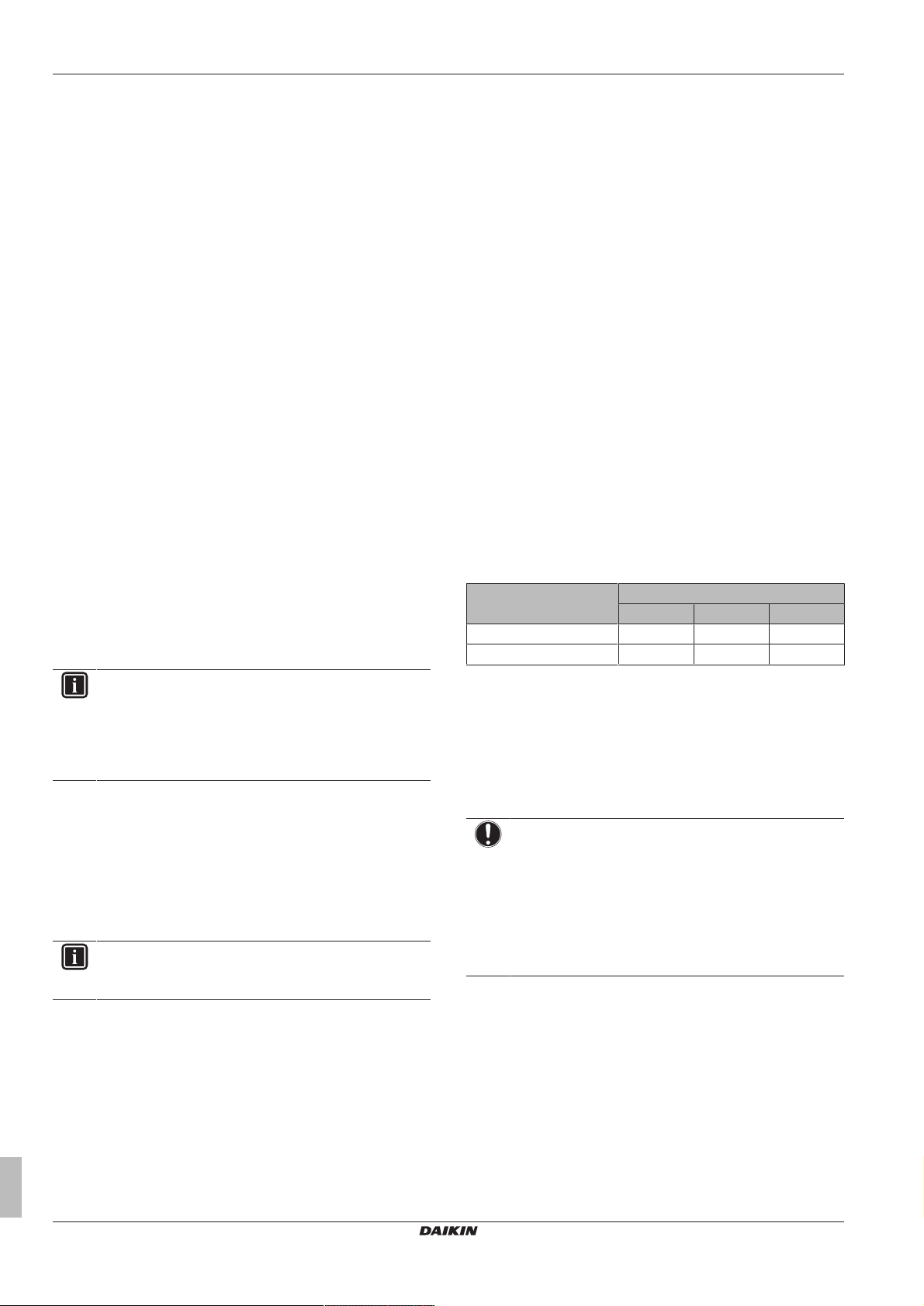
5.2.1 Single room
Underfloor heating or radiators – Wired room
thermostat
Setup
A Main leaving water temperature zone
B One single room
a User interface used as room thermostat
▪ The room temperature of the main room is controlled by the user
interface used as a room thermostat (optional equipment
EKRUDAS).
Configuration
Setting Value
Unit temperature control:
▪ #: [2.9]
▪ Code: [C-07]
Number of water temperature
zones:
▪ #: [4.4]
▪ Code: [7-02]
2 (Room thermostat): Unit
operation is decided based on
the ambient temperature of the
user interface.
0 (Single zone): Main
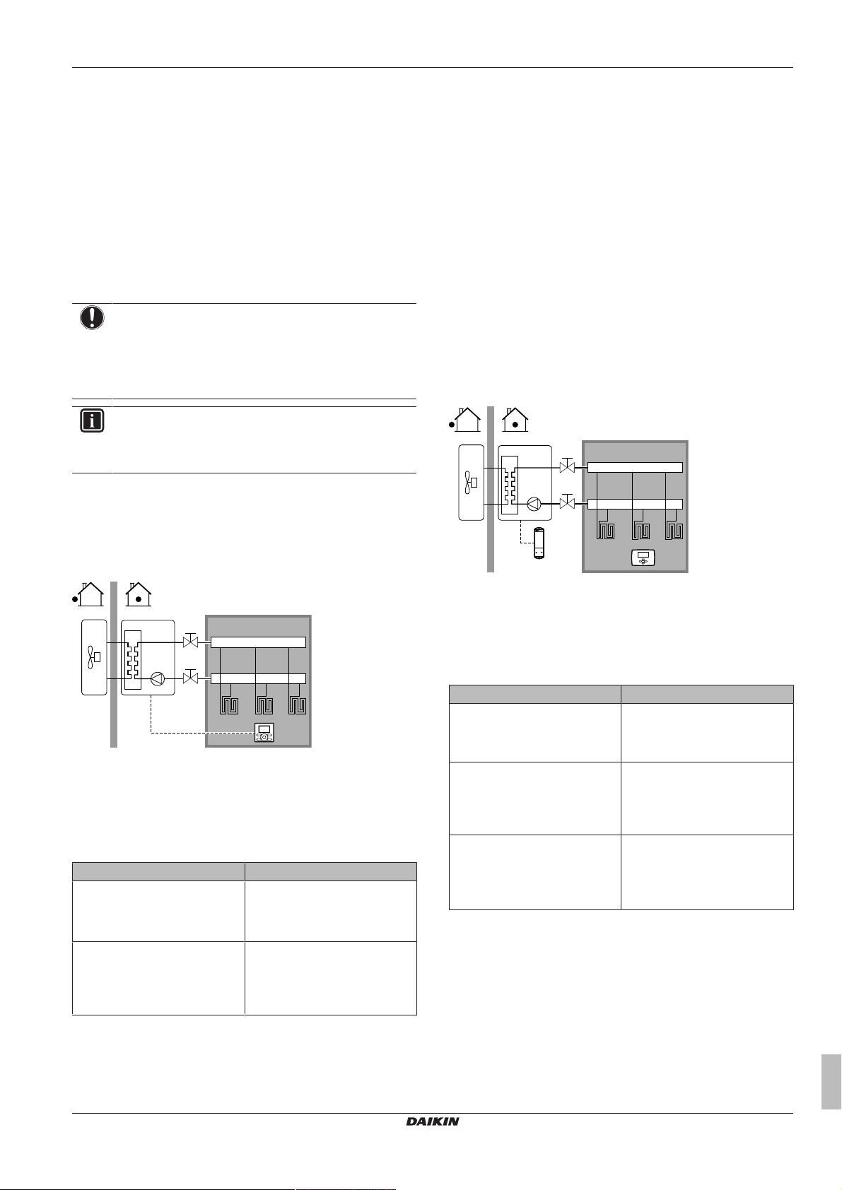
A Main leaving water temperature zone
B One single room
a Receiver for wireless external room thermostat
b Wireless external room thermostat
▪ The room temperature is controlled by the wireless external room
thermostat (optional equipment EKRTR1).
Configuration
Setting Value
Unit temperature control:
▪ #: [2.9]
▪ Code: [C-07]
Number of water temperature
zones:
▪ #: [4.4]
▪ Code: [7-02]
External room thermostat for the
main zone:
▪ #: [2.A]
▪ Code: [C-05]
Benefits
▪ Wireless. The Daikin external room thermostat is available in a
wireless version.
▪ Efficiency. Although the external room thermostat only sends ON/
OFF signals, it is specifically designed for the heatpump system.
1 (External room thermostat):
Unit operation is decided by the
external thermostat.
0 (Single zone): Main
1 (1 contact): When the used
external room thermostat or
heatpump convector can only
send a thermo ON/OFF
condition.
ERGA04~08DAV3(A) + EHVH04+08S23DAV
Daikin Altherma – Low temperature split
4P499573-1A – 2018.11
Installer reference guide
11
Page 12
5 Application guidelines
B
A
a
B
A
a
Heatpump convectors
Setup
▪ The heat pump convectors are directly connected to the indoor
unit.
▪ The desired room temperature is set via the remote controller of
the heatpump convectors.
▪ The space heating demand signal is sent to one digital input on
the indoor unit (X2M/35 and X2M/30).
▪ The space operation mode is sent to the heatpump convectors by
one digital output on the indoor unit (X2M/4 and X2M/3).
INFORMATION
When using multiple heat pump convectors, make sure
each one receives the infrared signal from the remote
controller of the heatpump convectors.
Configuration
Setting Value
Unit temperature control:
▪ #: [2.9]
▪ Code: [C-07]
Number of water temperature
zones:
▪ #: [4.4]
▪ Code: [7-02]
External room thermostat for the
main zone:
▪ #: [2.A]
▪ Code: [C-05]
Benefits
▪ Efficiency. Optimal energy efficiency because of the interlink
function.
▪ Stylish.
1 (External room thermostat):
Unit operation is decided by the
external thermostat.
0 (Single zone): Main
1 (1 contact): When the used
external room thermostat or
heatpump convector can only
send a thermo ON/OFF
condition.
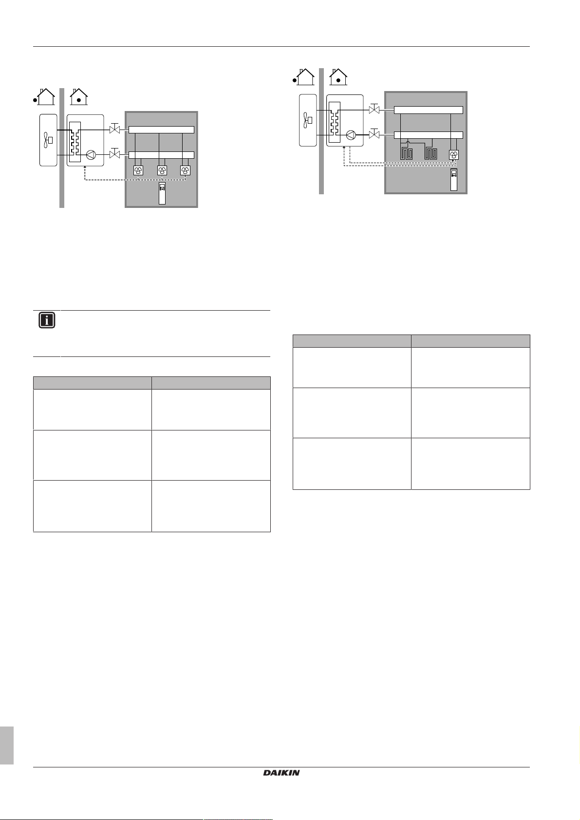
Combination: Underfloor heating + Heatpump
convectors
▪ Space heating is provided by:
▪ The underfloor heating
▪ The heatpump convectors
Setup
A Main leaving water temperature zone
B One single room
a Remote controller of the heatpump convectors
▪ The heat pump convectors are directly connected to the indoor
unit.
▪ The desired room temperature is set via the remote controller of
the heatpump convectors.
▪ The space heating demand signal is sent to one digital input on
the indoor unit (X2M/35 and X2M/30).
▪ The space operation mode is sent to the heat pump convectors by
one digital output (X2M/4 and X2M/3) on the indoor unit.
Configuration
Setting Value
Unit temperature control:
▪ #: [2.9]
▪ Code: [C-07]
Number of water temperature
zones:
▪ #: [4.4]
▪ Code: [7-02]
External room thermostat for the
main zone:
▪ #: [2.A]
▪ Code: [C-05]
Benefits
▪ Efficiency. Under floor heating has the best performance with
Altherma LT.
▪ Comfort. The combination of the two heat emitter types provides
excellent heating comfort of the underfloor heating.
1 (External room thermostat):
Unit operation is decided by the
external thermostat.
0 (Single zone): Main
1 (1 contact): When the used
external room thermostat or
heatpump convector can only
send a thermo ON/OFF
condition.
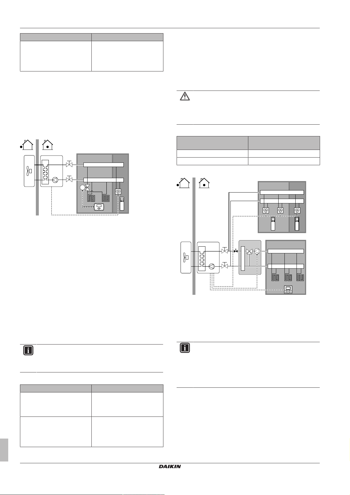
5.2.2 Multiple rooms – OneLWT zone
If only one leaving water temperature zone is needed because the
design leaving water temperature of all heat emitters is the same,
you do NOT need a mixing valve station (cost effective).
Example: If the heat pump system is used to heat up one floor
where all the rooms have the same heat emitters.
Underfloor heating or radiators – Thermostatic
valves
If you are heating up rooms with under floor heating or radiators, a
very common way is to control the temperature of the main room by
using a thermostat (this can either be the user interface or an
external room thermostat), while the other rooms are controlled by
so-called thermostatic valves, which open or close depending on the
room temperature.
Installer reference guide
12
ERGA04~08DAV3(A) + EHVH04+08S23DAV
Daikin Altherma – Low temperature split
4P499573-1A – 2018.11
Page 13
5 Application guidelines
T
B C
A
a
M2
B C
A
a
b
a
M1
B
A
a a
C
Setup
▪ The under floor heating of the main room is directly connected to
the indoor unit.
▪ The room temperature of the main room is controlled by the user
interface used as a room thermostat (optional equipment
EKRUDAS).
▪ A thermostatic valve is installed before the under floor heating in
each of the other rooms.
INFORMATION
Mind situations where the main room can be heated by
another heating source. Example: Fireplaces.
Configuration
Setting Value
Unit temperature control:
▪ #: [2.9]
▪ Code: [C-07]
Number of water temperature
2 (Room thermostat): Unit
operation is decided based on
the ambient temperature of the
user interface.
0 (Single zone): Main
zones:
▪ #: [4.4]
▪ Code: [7-02]
▪ The user interface connected on the indoor unit decides the space
operation mode. Mind that the operation mode on each room
thermostat must be set to match the indoor unit.
▪ The room thermostats are connected to the shut-off valves, but do
NOT have to be connected to the indoor unit. The indoor unit will
supply leaving water all the time, with the possibility to program a
leaving water schedule.
Configuration
Setting Value
Unit temperature control:
▪ #: [2.9]
0 (Leaving water): Unit operation
is decided based on the leaving
water temperature.
▪ Code: [C-07]
Number of water temperature
0 (Single zone): Main
zones:
▪ #: [4.4]
▪ Code: [7-02]
Benefits
Compared with underfloor heating or radiators for one room:
▪ Comfort. You can set the desired room temperature, including
schedules, for each room via the room thermostats.
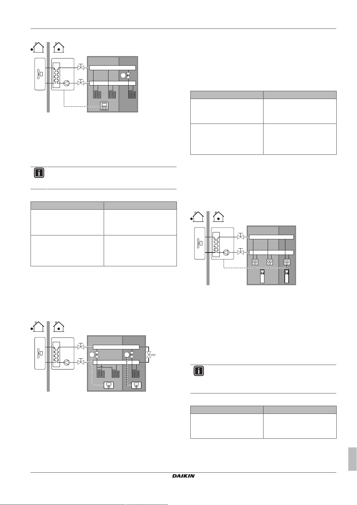
Heatpump convectors – Multiple rooms
Setup
Benefits
▪ Easy. Same installation as for one room, but with thermostatic
valves.
Underfloor heating or radiators – Multiple external
room thermostats
Setup
A Main leaving water temperature zone
B Room 1
C Room 2
a External room thermostat
b Bypass valve
▪ For each room, a shut-off valve (field supplied) is installed to avoid
leaving water supply when there is no heating demand.
▪ A bypass valve must be installed to make water recirculation
possible when all shut-off valves are closed. To guarantee reliable
operation, provide a minimum water flow as described in table "To
check the water volume and flow rate" in "6.4 Preparing water
piping"on page25.
ERGA04~08DAV3(A) + EHVH04+08S23DAV
Daikin Altherma – Low temperature split
4P499573-1A – 2018.11
A Main leaving water temperature zone
B Room 1
C Room 2
a Remote controller of the heatpump convectors
▪ The desired room temperature is set via the remote controller of
the heatpump convectors.
▪ The user interface connected on the indoor unit decides the space
operation mode.
▪ The heating demand signals of each heat pump convector are
connected in parallel to the digital input on the indoor unit (X2M/1
and X2M/4). The indoor unit will only supply leaving water
temperature when there is an actual demand.
INFORMATION
To increase comfort and performance, Daikin recommends
to install the valve kit option EKVKHPC on each heatpump
convector.
Configuration
Setting Value
Unit temperature control:
▪ #: [2.9]
1 (External room thermostat):
Unit operation is decided by the
external thermostat.
▪ Code: [C-07]
Installer reference guide
13
Page 14
5 Application guidelines
b
B C
A
a
M1
B
A
a a
C
E
D
b
c
d
Setting Value
Number of water temperature
0 (Single zone): Main
zones:
▪ #: [4.4]
▪ Code: [7-02]
Benefits
Compared with heatpump convectors for one room:
▪ Comfort. You can set the desired room temperature, including
schedules, for each room via the remote controller of the
heatpump convectors.
Combination: Underfloor heating + Heatpump
convectors – Multiple rooms
Setup
5.2.3 Multiple rooms – TwoLWT zones
If the heat emitters selected for each room are designed for different
leaving water temperatures, you can use different leaving water
temperature zones (maximum 2).
In this document:
▪ Main zone = Zone with the lowest design temperature
▪ Additional zone = Zone with the highest design temperature
CAUTION
When there is more than one leaving water zone, you must
ALWAYS install a mixing valve station in the main zone to
decrease (in heating) the leaving water temperature when
the additional zone has demand.
Typical example:
Room (zone) Heat emitters: Design
temperature
Living room (main zone) Underfloor heating: 35°C
Bed rooms (additional zone) Heatpump convectors: 45°C
Setup
A Main leaving water temperature zone
B Room 1
C Room 2
a External room thermostat
b Remote controller of the heatpump convectors
▪ For each room with heat pump convectors: The heat pump
convectors are directly connected to the indoor unit.
▪ For each room with under floor heating: A shut-off valve (field
supply) is installed before the underfloor heating. It prevents hot
water supply when the room has no heating demand.
▪ For each room with heat pump convectors: The desired room
temperature is set via the remote controller of the heat pump
convectors.
▪ For each room with under floor heating: The desired room
temperature is set via the external room thermostat (wired or
wireless).
▪ The user interface connected to the indoor unit decides the space
operation mode. Mind that the operation mode on each external
room thermostat and remote controller of the heat pump
convectors must be set to match the indoor unit.
INFORMATION
To increase comfort and performance, Daikin recommends
to install the valve kit option EKVKHPC on each heatpump
convector.
Configuration
Setting Value
Unit temperature control:
▪ #: [2.9]
0 (Leaving water): Unit operation
is decided based on the leaving
water temperature.
▪ Code: [C-07]
Number of water temperature
zones:
▪ #: [4.4]
▪ Code: [7-02]
0 (Single zone): Main
A Additional leaving water temperature zone
B Room 1
C Room 2
D Main leaving water temperature zone
E Room 3
a Remote controller of the heatpump convectors
b User interface used as room thermostat
c Mixing valve station
d Pressure regulating valve
INFORMATION
A pressure regulating valve should be implemented before
the mixing valve station. This is to guarantee the correct
water flow balance between the main leaving water
temperature zone and the additional leaving water
temperature zone in relation to the required capacity of
both water temperature zones.
▪ For the main zone:
▪ A mixing valve station is installed before the underfloor heating.
▪ The pump of the mixing valve station is controlled by the ON/
OFF signal on the indoor unit (X2M/29 and X2M/21; normal
closed shut-off valve output).
▪ The room temperature is controlled by the user interface, which
is used as room thermostat (optional equipment EKRUDAS).
Installer reference guide
14
ERGA04~08DAV3(A) + EHVH04+08S23DAV
Daikin Altherma – Low temperature split
4P499573-1A – 2018.11
Page 15
5 Application guidelines
a b c e f
f
g h j
FHL1
FHL2
FHL3
M
h
i
il
k
m
n
d
▪ For the additional zone:
▪ The heat pump convectors are directly connected to the indoor
unit.
▪ The desired room temperature is set via the remote controller of
the heatpump convectors for each room.
▪ The heating demand signals of each heatpump convector are
connected in parallel to the digital input on the indoor unit
(X2M/35 and X2M/30). The indoor unit will only supply the
desired additional leaving water temperature when there is an
actual demand.
▪ The user interface connected to the indoor unit decides the space
operation mode. Mind that the operation mode on each remote
controller of the heatpump convectors must be set to match the
indoor unit.
Configuration
Setting Value
Unit temperature control:
▪ #: [2.9]
▪ Code: [C-07]
2 (Room thermostat): Unit
operation is decided based on
the ambient temperature of the
user interface.
Note:
▪ Main room = user interface
used as room thermostat
functionality
▪ Other rooms = external room
thermostat functionality
Number of water temperature
1 (Dual zone): Main + additional
zones:
▪ #: [4.4]
▪ Code: [7-02]
In case of heatpump convectors:
External room thermostat for the
additional zone:
▪ #: [3.A]
1 (1 contact): When the used
external room thermostat or
heatpump convector can only
send a thermo ON/OFF
condition.
▪ Code: [C-06]
Shut-off valve output Set to follow the thermo demand
of the main zone.
At the mixing valve station Set the desired main leaving
water temperature.
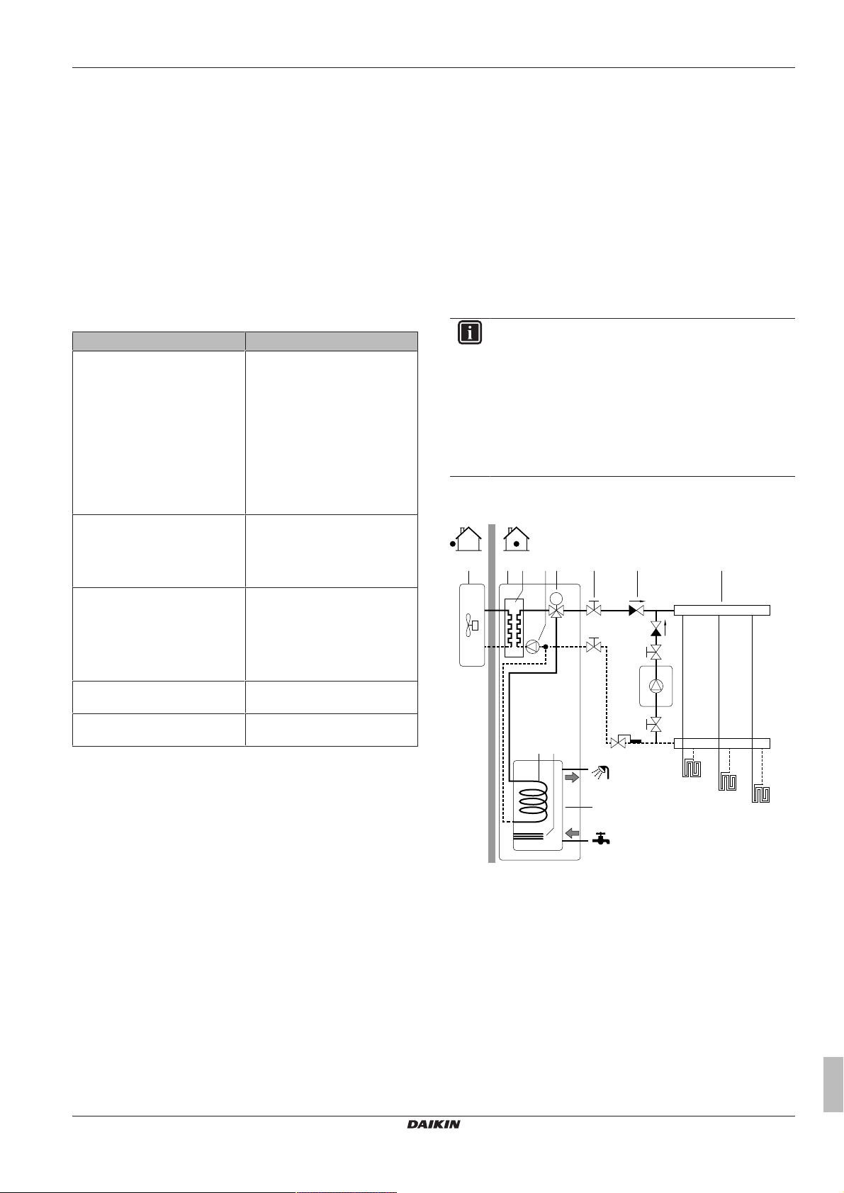
5.3 Setting up an auxiliary heat source for space heating
▪ Space heating can be done by:
▪ The indoor unit
▪ An auxiliary boiler (field supply) connected to the system
▪ When the room thermostat requests heating, the indoor unit or the
auxiliary boiler starts operating depending on the outdoor
temperature (status of the changeover to external heat source).
When the permission is given to the auxiliary boiler, the space
heating by the indoor unit is turned OFF.
▪ Bivalent operation is only possible for space heating, NOT for
domestic hot water production. Domestic hot water is always
produced by the DHW tank connected to the indoor unit.
INFORMATION
▪ During heating operation of the heat pump, the
heat pump operates to achieve the desired
temperature set via the user interface. When weatherdependent operation is active, the water temperature is
determined automatically depending on the outdoor
temperature.
▪ During heating operation of the auxiliary boiler, the
auxiliary boiler operates to achieve the desired water
temperature set via the auxiliary boiler controller.
Setup
▪ Integrate the auxiliary boiler as follows:
Benefits
▪ Comfort.
▪ The smart room thermostat functionality can decrease or
increase the desired leaving water temperature based on the
actual room temperature (modulation).
▪ The combination of the two heat emitter systems provides the
excellent heating comfort of the under floor heating, and the
rapid air heat up of the heat pump convectors (e.g., living
room=under floor heating and the bedroom=convector (no
continuous heating)).
▪ Efficiency.
▪ Depending on the demand, the indoor unit supplies different
leaving water temperature matching the design temperature of
the different heat emitters.
▪ Underfloor heating has the best performance with Altherma LT.
ERGA04~08DAV3(A) + EHVH04+08S23DAV
Daikin Altherma – Low temperature split
4P499573-1A – 2018.11
a Outdoor unit
b Indoor unit
c Heat exchanger
d Anti-legionella heater
e Pump
f Shut-off valve
g Motorised 3‑way valve
h Non-return valve (field supply)
i Shut-off valve (field supply)
j Collector (field supply)
k Auxiliary boiler (field supply)
l Aquastat valve (field supply)
m DHW tank
n Heat exchanger coil
FHL1...3 Underfloor heating
Installer reference guide
15
Page 16
5 Application guidelines
L
N
H
Com
A
K2AK1A
X2M
B
TI
K2AK1A
Indoor/Auto/Boiler
3530 X Y
Indoor
FHL1
FHL2
FHL3
M
UI
a b c hh if
e
g
d
NOTICE
▪ Make sure the auxiliary boiler and its integration in the
system complies with applicable legislation.
▪ Daikin is NOT responsible for incorrect or unsafe
situations in the auxiliary boiler system.
▪ Make sure the return water to the heatpump does NOT exceed
55°C. To do so:
▪ Set the desired water temperature via the auxiliary boiler
controller to maximum 55°C.
▪ Install an aquastat valve in the return water flow of the
heatpump.
▪ Set the aquastat valve to close above 55°C and to open below
55°C.
▪ Install non-return valves.
▪ Make sure to only have one expansion vessel in the water circuit.
An expansion vessel is already pre-mounted in the indoor unit.
▪ Install the digital I/O PCB (option EKRP1HB).
▪ Connect X1 and X2 (changeover to external heat source) on the
digital I/O PCB to the auxiliary boiler thermostat.
▪ To setup the heat emitters, see "5.2Setting up the space heating
system"on page11.
Configuration
Via the user interface (quick wizard):
▪ Set the use of a bivalent system as external heat source.
▪ Set the bivalent temperature and hysteresis.
K2A Auxiliary relay for activation of boiler (field supply)
Indoor Indoor unit
Auto Automatic
Boiler Boiler
NOTICE
▪ Make sure the auxiliary contact has enough differential
or time delay to prevent frequent changeover between
indoor unit and auxiliary boiler.
▪ If the auxiliary contact is an outdoor temperature
thermostat, install the thermostat in the shadow so that
it is NOT influenced or turned ON/OFF by direct
sunlight.
▪ Frequent changeover may cause corrosion of the
auxiliary boiler. Contact the manufacturer of the
auxiliary boiler for more information.
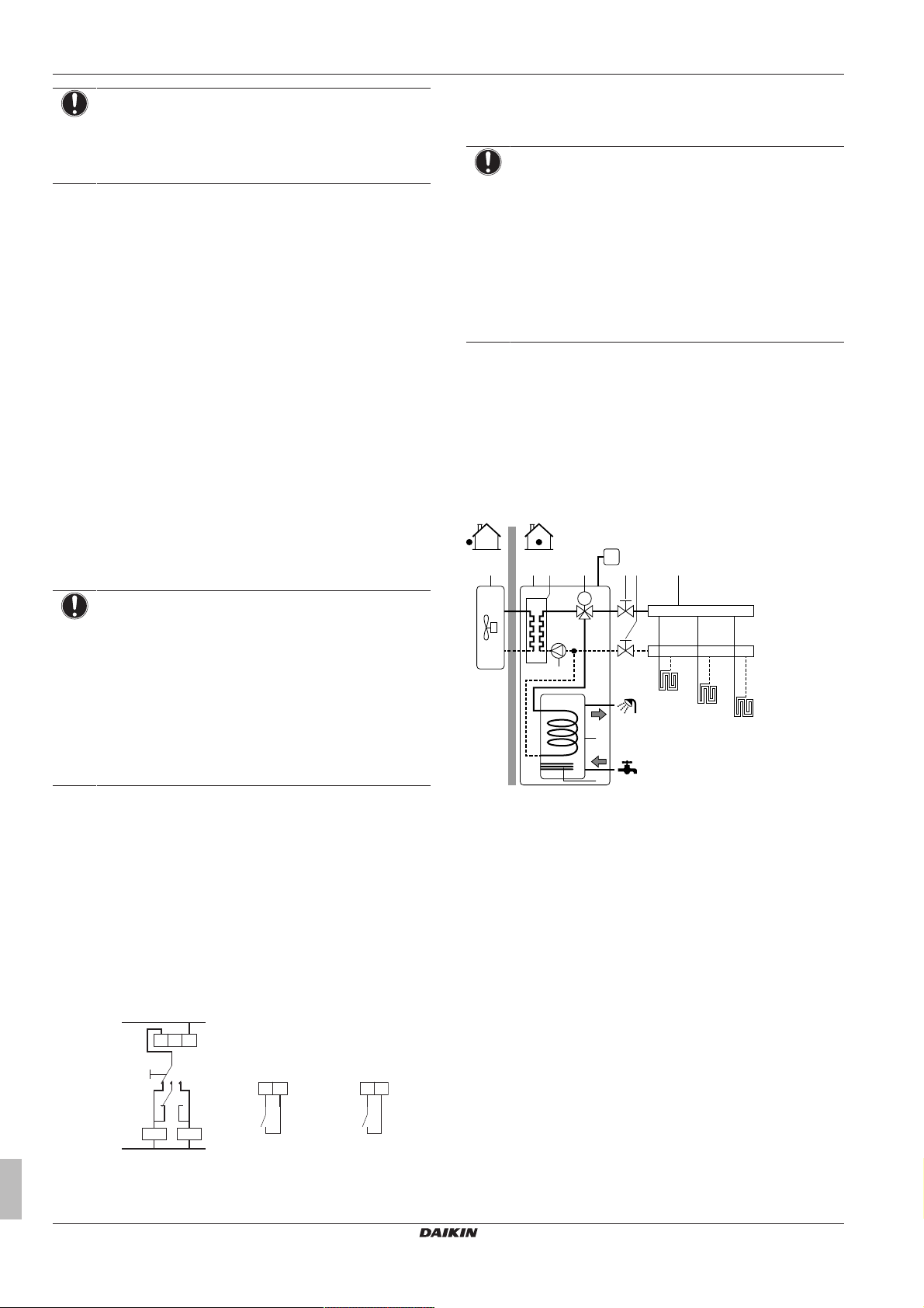
5.4 Setting up the domestic hot water tank
The DHW tank is integrated in the indoor unit, and contains a 2.4kW
anti-legionella heater. The anti-legionella heater contains 2 safeties:
a thermal cut-out and a thermal fuse. If a certain temperature is
exceeded, the safeties deactivate the anti-legionella heater.
5.4.1 System layout – Integrated DHW tank
Changeover to external heat source decided by an auxiliary
contact
▪ Only possible in external room thermostat control AND one
leaving water temperature zone (see "5.2 Setting up the space
heating system"on page11).
▪ The auxiliary contact can be:
▪ An outdoor temperature thermostat
▪ An electricity tariff contact
▪ A manually operated contact
▪ …
▪ Setup: Connect the following field wiring:
Installer reference guide
16
NOTICE
▪ Make sure the bivalent hysteresis has enough
differential to prevent frequent changeover between
indoor unit and auxiliary boiler.
▪ Because the outdoor temperature is measured by the
outdoor unit air thermistor, install the outdoor unit in the
shadow so that it is NOT influenced or turned ON/OFF
by direct sunlight.
▪ Frequent changeover may cause corrosion of the
auxiliary boiler. Contact the manufacturer of the
auxiliary boiler for more information.
BTIBoiler thermostat input
A Auxiliary contact (normal closed)
H Heating demand room thermostat (optional)
K1A Auxiliary relay for activation of indoor unit (field supply)
a Outdoor unit
b Indoor unit
c Heat exchanger
d Anti-legionella heater
e Pump
f Motorised 3‑way valve
g DHW tank
h Shut-off valve
i Collector (field supply)
FHL1...3 Underfloor heating
UI User interface
5.4.2 Selecting the volume and desired temperature for the DHW tank
People experience water as hot when its temperature is 40°C.
Therefore, the DHW consumption is always expressed as equivalent
hot water volume at 40°C. However, you can set the DHW tank
temperature at a higher temperature (example: 53°C), which is then
mixed with cold water (example: 15°C).
Selecting the desired temperature for the DHW tank consists of:
1 Determining the DHW consumption (equivalent hot water
volume at 40°C).
2 Determining the desired temperature for the DHW tank.
Determining the DHW consumption
Answer the following questions and calculate the DHW consumption
(equivalent hot water volume at 40°C) using typical water volumes:
ERGA04~08DAV3(A) + EHVH04+08S23DAV
Daikin Altherma – Low temperature split
4P499573-1A – 2018.11
Page 17

5 Application guidelines
c
f
a
j
b
g
h
i
c
a
d f
e g
h
i
j
b
Question Typical water volume
How many showers are needed
per day?
How many baths are needed per
day?
How much water is needed at the
kitchen sink per day?
Are there any other domestic hot
water needs?
1shower = 10min×10l/min =
100l
1bath = 150l
1sink = 2min×5l/min = 10l
—
▪ The higher the outdoor temperature, the better the performance of
the heatpump.
▪ If energy prices are the same during the day and the night,
Daikin recommends to heat up the DHW tank during the day.
▪ If energy prices are lower during the night, Daikin recommends
to heat up the DHW tank during the night.
▪ When the heatpump produces domestic hot water, it cannot heat
up a space. In case you need domestic hot water and space
heating at the same, Daikin recommends to produce the domestic
hot water during the night when there is lower space heating
Example: If the DHW consumption of a family (4 persons) per day
demand.
is as follows:
▪ 3 showers
▪ 1 bath
▪ 3 sink volumes
Then the DHW consumption = (3×100l)+(1×150l)+(3×10l)=480l
Determining the volume and desired temperature for the DHW
tank
Formula Example
V1=V2+V2×(T2−40)/(40−T1) If:
▪ V2=180l
▪ T2=54°C
▪ T1=15°C
5.4.3 Setup and configuration – DHW tank
▪ For large DHW consumptions, you can heat up the DHW tank
several times during the day.
▪ To heat up the DHW tank to the desired DHW tank temperature,
you can use the following energy sources:
▪ Thermodynamic cycle of the heatpump
▪ Anti-legionella heater
▪ For more information about optimizing the energy consumption for
producing domestic hot water, see "8Configuration"on page47.
5.4.4 DHW pump for instant hot water
Setup
Then V1=280l
V2=V1×(40−T1)/(T2−T1) If:
▪ V1=480l
▪ T2=54°C
▪ T1=15°C
Then V2=307l
V1DHW consumption (equivalent hot water volume at 40°C)
V2Required DHW tank volume if only heated once
T2DHW tank temperature
T1Cold water temperature
Possible DHW tank volumes
Type Possible volumes
Integrated DHW tank ▪ 230l
Energy saving tips
▪ If the DHW consumption differs from day to day, you can program
a weekly schedule with different desired DHW tank temperatures
for each day.
▪ The lower the desired DHW tank temperature, the more cost
effective. By selecting a larger DHW tank, you can lower the
desired DHW tank temperature.
▪ The heatpump itself can produce domestic hot water of maximum
55°C (50°C if outdoor temperature is low). The electrical
▪ By connecting a DHW pump, instant hot water can be available at
the tap.
▪ The DHW pump and the installation are field supply and the
responsibility of the installer.
▪ For more information about connecting the recirculation
connection: see "7Installation"on page29.
Configuration
▪ For more information, see "8Configuration"on page47.
▪ You can program a schedule to control the DHW pump via the
user interface. For more information, see the user reference
guide.
a Indoor unit
b DHW tank
c DHW pump (field supply)
f Shower (field supply)
g Cold water
h Domestic hot water OUT
i Recirculation connection
j Anti-legionella heater
resistance integrated in the DHW tank (anti-legionella heater) can
increase this temperature. However, this consumes more energy.
Daikin recommends to set the desired DHW tank temperature
below 55°C to avoid using the electrical resistance.
5.4.5 DHW pump for disinfection
Setup
The anti-legionella heater:
▪ Is used as emergency heater.
▪ Is used when the disinfection function for the DHW tank is
active.
▪ Can assist during defrost operation for the outdoor unit.
a Indoor unit
b DHW tank
c DHW pump (field supply)
d Heater element (field supply)
e Non‑return valve (field supply)
f Shower (field supply)
g Cold water
ERGA04~08DAV3(A) + EHVH04+08S23DAV
Daikin Altherma – Low temperature split
4P499573-1A – 2018.11
Installer reference guide
17
Page 18
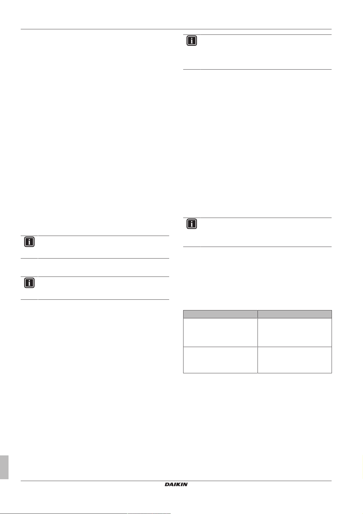
5 Application guidelines
h Domestic hot water OUT
i Recirculation connection
j Anti-legionella heater
▪ The DHW pump is field-supplied and its installation is the
responsibility of the installer.
▪ The temperature of the DHW tank can be set to maximum 70°C. If
the applicable legislation requires a higher temperature for
disinfection, you can connect a DHW pump and heater element as
shown above.
▪ If applicable legislation requires disinfection of the water piping
until the tapping point, you can connect a DHW pump and heater
element (if needed) as shown above.
Configuration
The indoor unit can control DHW pump operation. For more
information, see "8Configuration"on page47.
5.5 Setting up the energy metering
▪ Via the user interface, you can read out the following energy data:
▪ Produced heat
▪ Consumed energy
▪ You can read out the energy data:
▪ For space heating
▪ For domestic hot water production
▪ You can read out the energy data:
▪ Per month
▪ Per year
INFORMATION
The calculated produced heat and consumed energy are
an estimation, the accuracy cannot be guaranteed.
INFORMATION
You cannot combine calculating the consumed energy
(example: for anti‑legionella heater) and measuring the
consumed energy (example: for outdoor unit). If you do so,
the energy data will be invalid.
Calculating the consumed energy
▪ The consumed energy is calculated internally based on:
▪ The actual power input of the outdoor unit
▪ The set capacity of the backup heater (if applicable) and anti-
legionella heater
▪ The voltage
▪ Setup and configuration: To get accurate energy data, measure
the capacity (resistance measurement) and set the capacity via
the user interface for:
▪ The backup heater (step1 and step2) (if applicable)
▪ The anti-legionella heater
Measuring the consumed energy
▪ Applicable for all models.
▪ Preferred method because of higher accuracy.
▪ Requires external power meters.
▪ Setup and configuration: When using electrical power meters, set
the number of pulses/kWh for each power meter via the user
interface.
INFORMATION
When measuring the electrical power consumption, make
sure ALL power input of the system is covered by the
electrical power meters.
5.5.3 Normal kWh rate power supply
5.5.1 Produced heat
INFORMATION
The sensors used to calculate the produced heat are
calibrated automatically.
▪ Applicable for all models.
▪ The produced heat is calculated internally based on:
▪ The leaving and entering water temperature
▪ The flow rate
▪ The power consumption of the anti-legionella heater in the
domestic hot water tank
▪ Setup and configuration:
▪ No additional equipment needed.
▪ Measure the capacity (resistance measurement) of the anti-
legionella heater and set the capacity via the user interface.
Example: If you measure an anti-legionella heater resistance of
24Ω, the capacity of the heater at 230V is 2200W.
5.5.2 Consumed energy
You can use the following methods to determine the consumed
energy:
▪ Calculating
▪ Measuring
General rule
One power meter that covers the entire system is sufficient.
Setup
Connect the power meter to X5M/5 and X5M/6.
Power meter type
In case of… Use a… power meter
▪ Single-phase outdoor unit
▪ No backup heater or optional
backup heater supplied from a
single-phase grid
In other cases (i.e. a three-phase
outdoor unit and/or optional
backup heater connected to a
three-phase grid)
Single-phase
Three-phase
Installer reference guide
18
ERGA04~08DAV3(A) + EHVH04+08S23DAV
Daikin Altherma – Low temperature split
4P499573-1A – 2018.11
Page 19
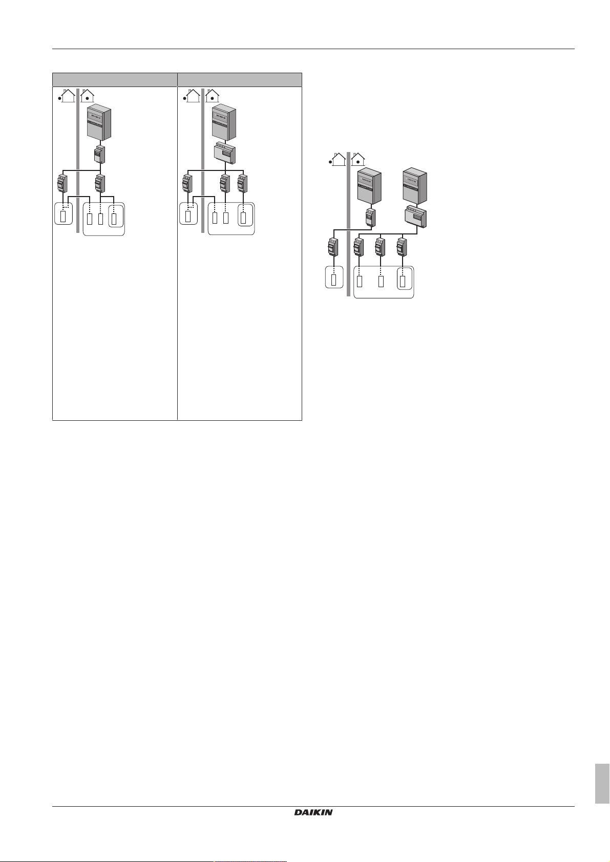
5 Application guidelines
b
5
8
0
1
5
0
0
0
c c
fe
d
g
A
B
C
a
b
5
8
0
1
5
0
0
0
gf
e
h
A
B
C
c c d
a
e efe
ih
g
j
A
B
C
ba
d
c
5
8
0
1
5
0
0
0
5
8
0
1
5
0
0
0
Example
Single-phase power meter Three-phase power meter
A Outdoor unit
B Indoor unit
C DHW tank
a Electrical cabinet (L1/N)
b Power meter (L1/N)
c Fuse (L1/N)
d Outdoor unit (L1/N)
e Indoor unit (L1/N)
f Backup heater (L1/N) (optional)
g Anti-legionella heater (L1/N)
A Outdoor unit
B Indoor unit
C DHW tank
a Electrical cabinet (L1/L2/L3/N)
b Power meter (L1/L2/L3/N)
c Fuse (L1/L2/L3/N)
d Fuse (L1/N)
e Outdoor unit (L1/L2/L3/N)
f Indoor unit (L1/L2/L3/N)
g Backup heater (L1/L2/L3/N)
(optional)
h Anti-legionella heater (L1/N)
Exception
▪ You can use a second power meter if:
▪ The power range of one meter is insufficient.
▪ The electrical meter cannot easily be installed in the electrical
cabinet.
▪ 230 V and 400 V three-phase grids are combined (very
uncommon), because of technical limitations of power meters.
▪ Connection and setup:
▪ Connect the second power meter to X5M/3 and X5M/4.
▪ In the software the power consumption data of both meters is
added so you do NOT have to set which meter covers which
power consumption. You only need to set the number of pulses
of each power meter.
▪ See "5.5.4 Preferential kWh rate power supply"on page 19 for
an example with two power meters.
5.5.4 Preferential kWh rate power supply
General rule
▪ Power meter1: Measures the outdoor unit.
▪ Power meter 2: Measures the rest (i.e. indoor unit, optional
backup heater, and anti-legionella heater).
Setup
▪ Connect power meter1 to X5M/5 and X5M/6.
▪ Connect power meter2 to X5M/3 and X5M/4.
Power meter types
▪ Power meter1: Single- or three-phase power meter according to
the power supply of the outdoor unit.
▪ Power meter2:
▪ In case of no backup heater or an optional single-phase backup
heater configuration, use a single-phase power meter.
▪ In other cases, use a three-phase power meter.
Example
Single-phase outdoor unit with an optional three-phase backup
heater:
A Outdoor unit
B Indoor unit
C DHW tank
a Electrical cabinet (L1/N): Preferential kWh rate power
supply
b Electrical cabinet (L1/L2/L3/N): Normal kWh rate power
supply
c Power meter (L1/N)
d Power meter (L1/L2/L3/N)
e Fuse (L1/N)
f Fuse (L1/L2/L3/N)
g Outdoor unit (L1/N)
h Indoor unit (L1/N)
i Backup heater (L1/L2/L3/N) (optional)
j Anti-legionella heater (L1/N)
5.6 Setting up the power consumption control
▪ The power consumption control:
▪ Allows you to limit the power consumption of the entire system
(sum of outdoor unit, indoor unit, anti-legionella heater, and
optional backup heater).
▪ Configuration: Set the power limitation level and how it has to
be achieved via the user interface.
▪ The power limitation level can be expressed as:
▪ Maximum running current (inA)
▪ Maximum power input (inkW)
▪ The power limitation level can be activated:
▪ Permanently
▪ By digital inputs
5.6.1 Permanent power limitation
Permanent power limitation is useful to assure a maximum power or
current input of the system. In some countries, legislation limits the
maximum power consumption for space heating and DHW
production.
ERGA04~08DAV3(A) + EHVH04+08S23DAV
Daikin Altherma – Low temperature split
4P499573-1A – 2018.11
Installer reference guide
19
Page 20
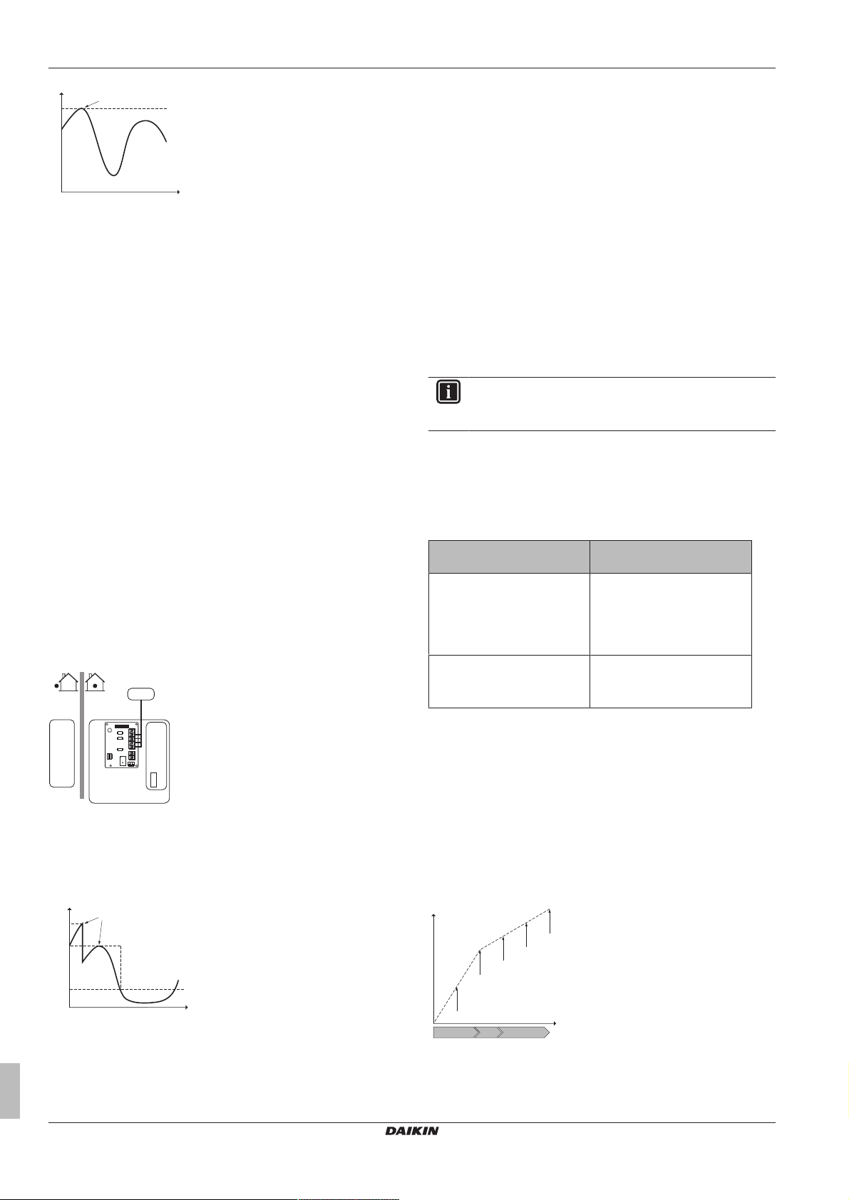
5 Application guidelines
P
i
t
DI
a
b
a
b
A
B
C
D
1
2
3
4
5
A8P
P
i
t
DI4
DI3
DI1
a
b
P
h
C
e
a
b
c
d
e
A B C
PiPower input
t Time
DI Digital input (power limitation level)
a Power limitation active
b Actual power input
Setup and configuration
▪ No additional equipment needed.
▪ Set the power consumption control settings in [9.9] via the user
interface (for the description of all settings, see
"8Configuration"on page47):
▪ Select continuous limitation mode
▪ Select the type of limitation (power in kW or current in A)
▪ Set the desired power limitation level
5.6.2 Power limitation activated by digital inputs
Power limitation is also useful in combination with an energy
management system.
The power or current of the entire Daikin system is limited
dynamically by digital inputs (maximum four steps). Each power
limitation level is set via the user interface by limiting one of the
following:
▪ Current (in A)
▪ Power input (in kW)
The energy management system (field supply) decides the activation
of a certain power limitation level. Example: To limit the maximum
power of the entire house (lighting, domestic appliances, space
heating…).
Setup
▪ Demand PCB (option EKRP1AHTA) needed.
▪ Maximum four digital inputs are used to activate the
corresponding power limitation level:
▪ DI1 = weakest limitation (highest energy consumption)
▪ DI4 = strongest limitation (lowest energy consumption)
▪ For the specifications of the digital inputs, and for where to
connect them, refer to the wiring diagram.
Configuration
▪ Set the power consumption control settings in [9.9] via the user
interface (for the description of all settings, see
"8Configuration"on page47):
▪ Select limitation by digital inputs.
▪ Select the type of limitation (power in kW or current in A).
▪ Set the desired power limitation level corresponding to each
digital input.
INFORMATION
In case more than 1 digital input is closed (at the same
time), the digital input priority is fixed: DI4 priority>…>DI1.
5.6.3 Power limitation process
The outdoor unit has better efficiency than the electrical heaters.
Therefore, the electrical heaters are limited and turned OFF first.
The system limits power consumption in the following order:
1 Limits certain electrical heaters.
If… has priority Then set the priority heater
via the user interface to…
Domestic hot water production Booster heater (Anti-legionella
heater).
Result: The backup heater (if
applicable) will be turned OFF
first.
Space heating Backup heater (if applicable).
Result: The anti-legionella
heater will be turned OFF first.
A Outdoor unit
B Indoor unit
C DHW tank
D Energy management system
a Power limitation activation (4 digital inputs)
b Anti-legionella heater
PiPower input
t Time
DI Digital inputs (power limitation levels)
a Power limitation active
b Actual power input
Installer reference guide
20
2 Turns OFF all electrical heaters.
3 Limits the outdoor unit.
4 Turns OFF the outdoor unit.
Example
If the configuration is as follows:
▪ Power limitation level does NOT allow operation of both anti-
legionella heater and backup heater (step 1 and step 2) (if
applicable).
▪ Priority heater = Anti-legionella heater.
Then power consumption is limited as follows:
PhProduced heat
CeConsumed energy
A Outdoor unit
B Anti-legionella heater
C Backup heater (optional)
a Limited outdoor unit operation
ERGA04~08DAV3(A) + EHVH04+08S23DAV
Daikin Altherma – Low temperature split
4P499573-1A – 2018.11
Page 21
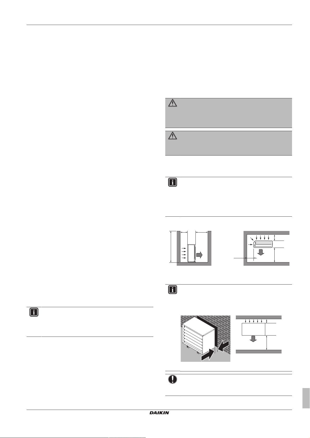
6 Preparation
≤1200
>250
>250
>250
>350
>350
(mm)(mm)
a
b
b
a
>100
>350
(mm)
>100
a
a
b Full outdoor unit operation
c Anti-legionella heater turned ON
d Backup heater step1 turned ON (if applicable)
e Backup heater step2 turned ON (if applicable)
5.7 Setting up an external temperature sensor
You can connect one external temperature sensor. It can measure
the indoor or outdoor ambient temperature. Daikin recommends to
use an external temperature sensor in the following cases:
Indoor ambient temperature
▪ In room thermostat control, the user interface used as room
thermostat (EKRUDAS) measures the indoor ambient
temperature. Therefore, the user interface used as room
thermostat must be installed on a location:
▪ Where the average temperature in the room can be detected
▪ That is NOT exposed to direct sunlight
▪ That is NOT near a heat source
▪ That is NOT affected by outside air or air draught because of,
for example, door opening/closing
▪ If this is NOT possible, Daikin recommends to connect a remote
indoor sensor (option KRCS01-1).
▪ Setup: For installation instructions, see the installation manual of
the remote indoor sensor.
▪ Configuration: Select room sensor [9.B].
Outdoor ambient temperature
▪ In the outdoor unit, the outdoor ambient temperature is measured.
Therefore, the outdoor unit must be installed on a location:
▪ At the north side of the house or at the side of the house where
the most heat emitters are located
▪ That is NOT exposed to direct sunlight
▪ If this is NOT possible, Daikin recommends to connect a remote
outdoor sensor (option EKRSCA1).
▪ Setup: For installation instructions, see the installation manual of
the remote outdoor sensor.
▪ Configuration: Select outdoor sensor [9.B].
▪ When the power saving functionality of the outdoor unit is active
(see "8 Configuration" on page 47), the outdoor unit is turned
down to reduce standby energy losses. As a result, the outdoor
ambient temperature is NOT read out.
▪ If the desired leaving water temperature is weather dependent, the
full time outdoor temperature measurement is important. This is
another reason to install the optional outdoor ambient temperature
sensor.
INFORMATION
The external outdoor ambient sensor data (either averaged
or instantaneous) is used in the weather-dependent control
curves. To protect the outdoor unit, the internal sensor of
the outdoor unit is always used.
▪ Preparing the refrigerant piping
▪ Preparing the water piping
▪ Preparing the electrical wiring
6.2 Preparing the installation site
Do NOT install the unit in places often used as work place. In case
of construction works (e.g. grinding works) where a lot of dust is
created, the unit MUST be covered.
Choose an installation location with sufficient space for carrying the
unit in and out of the site.
WARNING
The appliance shall be stored in a room without
continuously operating ignition sources (example: open
flames, an operating gas appliance or an operating electric
heater).
WARNING
DO NOT reuse refrigerant piping that has been used with
any other refrigerant. Replace the refrigerant pipes or
clean thoroughly.
6.2.1 Installation site requirements of the outdoor unit
INFORMATION
Also read the following requirements:
▪ General installation site requirements. See the
"General safety precautions" chapter.
▪ Refrigerant piping requirements (length, height
difference). See further in this "Preparation" chapter.
Mind the following spacing guidelines:
a Air outlet
b Air inlet
INFORMATION
In sound sensitive areas (e.g. near a bedroom), you can
install the low sound cover (EKLN08A1) to decrease the
operation noise of the outdoor unit. If you install it, mind the
following spacing guidelines:
6 Preparation
6.1 Overview: Preparation
This chapter describes what you have to do and know before going
on-site.
It contains information about:
▪ Preparing the installation site
ERGA04~08DAV3(A) + EHVH04+08S23DAV
Daikin Altherma – Low temperature split
4P499573-1A – 2018.11
a Low sound cover
NOTICE
▪ Do NOT stack the units on each other.
▪ Do NOT hang the unit on a ceiling.
Installer reference guide
21
Page 22
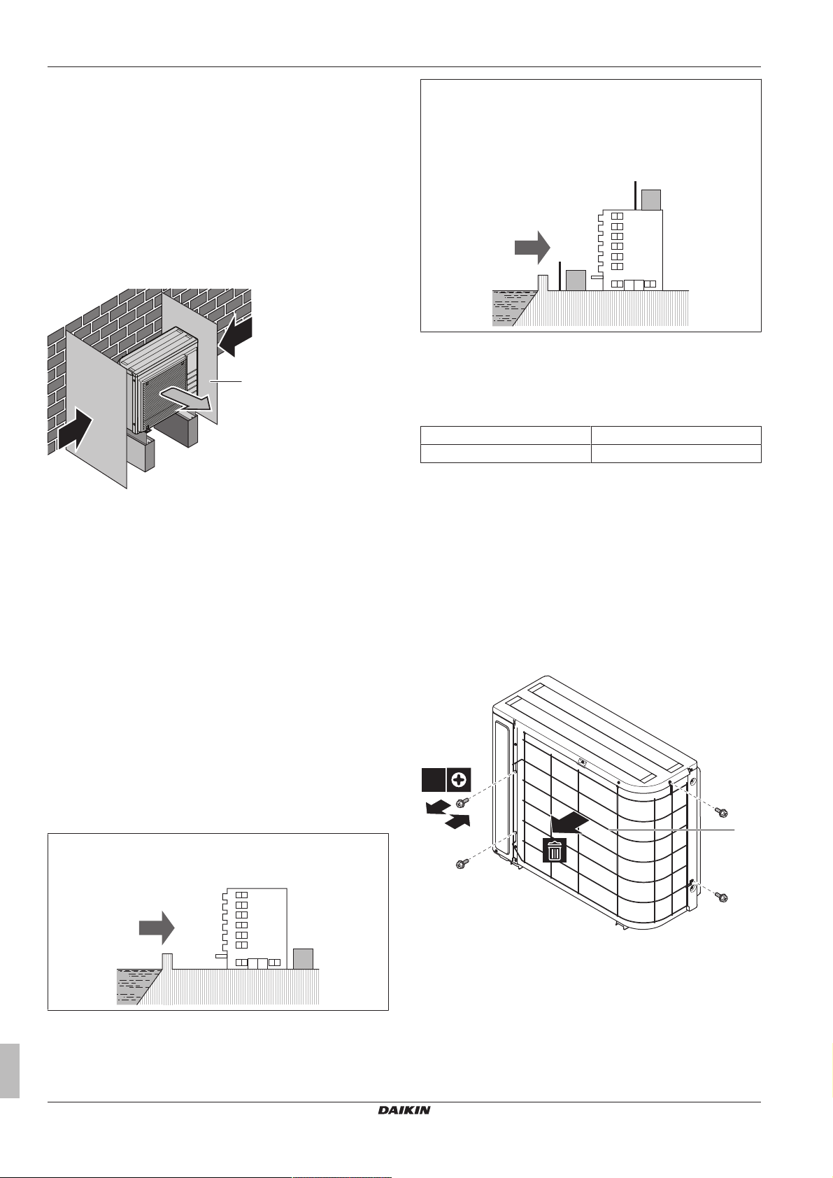
6 Preparation
b
b
c
a
b
c
a
a
b
c
d
c
d
2
4×
1
3
a
Strong winds (≥18 km/h) blowing against the outdoor unit’s air outlet
causes short circuit (suction of discharge air). This may result in:
▪ deterioration of the operational capacity;
▪ frequent frost acceleration in heating operation;
▪ disruption of operation due to decrease of low pressure or
increase of high pressure;
▪ a broken fan (if a strong wind blows continuously on the fan, it
may start rotating very fast, until it breaks).
It is recommended to install a baffle plate when the air outlet is
exposed to wind.
It is recommended to install the outdoor unit with the air inlet facing
the wall and NOT directly exposed to the wind.
a Baffle plate
b Prevailing wind direction
c Air outlet
Do NOT install the unit in the following places:
▪ Sound sensitive areas (e.g. near a bedroom), so that the
operation noise will cause no trouble.
Note: If the sound is measured under actual installation
conditions, the measured value might be higher than the sound
pressure level mentioned in Sound spectrum in the data book due
to environmental noise and sound reflections.
▪ In places where a mineral oil mist, spray or vapour may be
present in the atmosphere. Plastic parts may deteriorate and fall
off or cause water leakage.
It is NOT recommended to install the unit in the following places
because it may shorten the life of the unit:
▪ Where the voltage fluctuates a lot
▪ In vehicles or vessels
▪ Where acidic or alkaline vapour is present
Seaside installation. Make sure the outdoor unit is NOT directly
exposed to sea winds. This is to prevent corrosion caused by high
levels of salt in the air, which might shorten the life of the unit.
If the outdoor unit is exposed to direct sea winds, install a
windbreaker.
▪ Height of windbreaker≥1.5×height of outdoor unit
▪ Mind the service space requirements when installing the
windbreaker.
a Sea wind
b Building
c Outdoor unit
d Windbreaker
The outdoor unit is designed for outdoor installation only, and for the
following ambient temperatures:
Cooling mode 10~43°C
Heating mode –25~25°C
6.2.2 Additional installation site requirements of the outdoor unit in cold climates
In areas with low ambient temperatures and high humidity, or in
areas with heavy snowfall, remove the suction grille to ensure proper
operation.
Non-exhaustive list of areas: Austria, Czech Republic, Denmark,
Estonia, Finland, Germany, Hungary, Latvia, Lithuania, Norway,
Poland, Romania, Serbia, Slovakia, Sweden, …
1 Remove the screws holding the suction grille.
2 Remove the suction grille, and dispose of it.
3 Reattach the screws to the unit.
Install the outdoor unit away from direct sea winds.
Example: Behind the building.
Installer reference guide
22
a Suction grille
Protect the outdoor unit against direct snowfall and take care that the
outdoor unit is NEVER snowed up.
ERGA04~08DAV3(A) + EHVH04+08S23DAV
Daikin Altherma – Low temperature split
4P499573-1A – 2018.11
Page 23
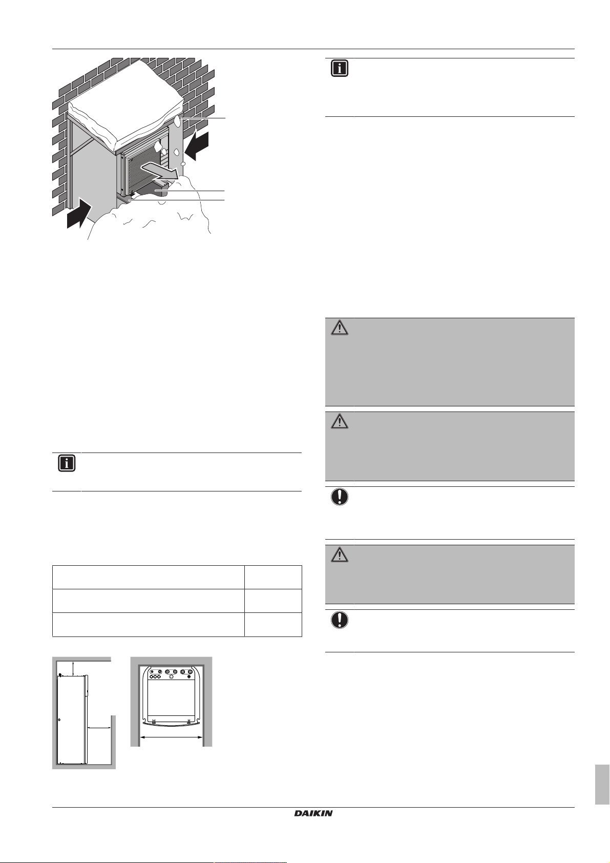
c
c
d
b
e
a
a Snow cover or shed
≥300
≥600
≥
500
(mm)
b Pedestal
c Prevailing wind direction
d Air outlet
e EKFT008D option kit
In any case, provide at least 300mm of free space below the unit.
Additionally, make sure the unit is positioned at least 100mm above
the maximum expected level of snow. See "7.3 Mounting the
outdoor unit"on page31 for more details.
In heavy snowfall areas it is very important to select an installation
site where the snow will NOT affect the unit. If lateral snowfall is
possible, make sure that the heat exchanger coil is NOT affected by
the snow. If necessary, install a snow cover or shed and a pedestal.
See also
2 7.3 Mounting the outdoor unit [}31]
6.2.3 Installation site requirements of the indoor unit
INFORMATION
Also read the precautions and requirements in the
"General safety precautions" chapter.
▪ The indoor unit is designed for indoor installation only and for the
following ambient temperatures:
▪ Space heating operation: 5~30°C
▪ Domestic hot water production: 5~35°C
▪ Mind the following measurements guidelines:
Maximum refrigerant piping length between indoor
unit and outdoor unit
Minimum refrigerant piping length between indoor
unit and outdoor unit
Maximum height difference between indoor unit and
outdoor unit
▪ Mind the following spacing installation guidelines:
30m
3m
20m
6 Preparation
INFORMATION
If you have limited installation space, do the following
before installing the unit in its final position: "7.4.4 To
connect the drain hose to the drain" on page 34. It
requires to remove one or both side panels.
▪ The foundation must be strong enough to bear the weight of the
unit. Take the weight of the unit with a domestic hot water tank full
of water into account.
Make sure, in the event of a water leak, water cannot cause any
damage to the installation space and surroundings.
Do NOT install the unit in places such as:
▪ In places where a mineral oil mist, spray or vapour may be
present in the atmosphere. Plastic parts may deteriorate and fall
off or cause water leakage.
▪ Sound sensitive areas (e.g. near a bedroom), so that the
operation noise will cause no trouble.
▪ In places with high humidity (max. RH=85%), for example a
bathroom.
▪ In places where frost is possible. Ambient temperature around the
indoor unit must be >5°C.
Special requirements for R32
WARNING
▪ Do NOT pierce or burn.
▪ Do NOT use means to accelerate the defrosting
process or to clean the equipment, other than those
recommended by the manufacturer.
▪ Be aware that R32 refrigerant does NOT contain an
odour.
WARNING
The appliance shall be stored so as to prevent mechanical
damage and in a well-ventilated room without continuously
operating ignition sources (example: open flames, an
operating gas appliance or an operating electric heater)
and have a room size as specified below.
NOTICE
▪ Do NOT re-use joints which have been used already.
▪ Joints made in installation between parts of refrigerant
system shall be accessible for maintenance purposes.
WARNING
Make sure installation, servicing, maintenance and repair
comply with instructions from Daikin and with applicable
legislation (for example national gas regulation) and are
executed only by authorised persons.
NOTICE
▪ Pipework shall be protected from physical damage.
▪ Installation of pipework shall be kept to a minimum.
ERGA04~08DAV3(A) + EHVH04+08S23DAV
Daikin Altherma – Low temperature split
4P499573-1A – 2018.11
Installer reference guide
23
Page 24
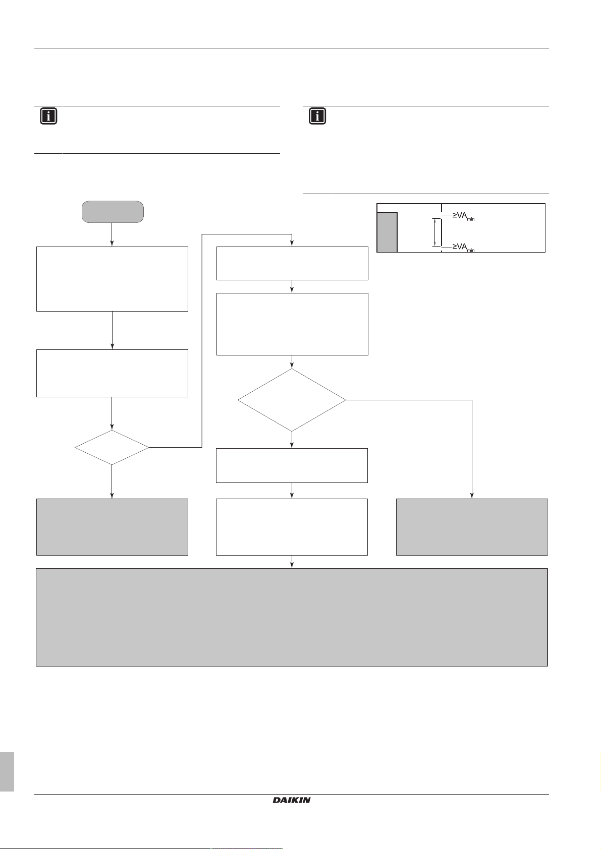
6 Preparation
Input from installer:
▪ Total refrigerant charge (m
c
) (kg)
▪ Area of room A (A
room A
) (m2)
Start
Use table 1 in chapter "Technical data" to
calculate the maximum refrigerant charge
(m
max
) (kg) allowed for room A.
Contact your dealer.
Use table 3 in chapter "Technical data" and
dm to calculate the minimum opening area for
natural ventilation between room A and
room B (VA
min
) (cm2).
Unit can be installed at room A if:
▪ 2 ventilation openings (permanently open) are provided between room A and B, 1 at the top and 1 at the bottom.
▪ Bottom opening: The bottom opening must meet the minimum area requirements (VA
min
). It must be as close as possible to the floor. If the ventilation opening
starts from the floor, the height must be ≥20 mm. The bottom of the opening must be situated ≤100 mm from the floor. At least 50% of the required opening
area must be situated <200 mm from the floor. The entire area of the opening must be situated <300 mm from the floor.
▪ Top opening: The area of the top opening must be larger than or equal to the bottom opening. The bottom of the top opening must be situated at least 1.5 m
above the top of the bottom opening.
▪ Ventilation openings to the outside are NOT considered suitable ventilation openings (the user can block them when it is cold).
The unit can be installed in room A, and
without further room size or ventilation
requirements.
Determine the refrigerant amount that exceeds
m
max
(dm) (kg). (dm=mc–m
max
)
m
max≥mc
?
Yes
No
No
Use table 2 in chapter "Technical data" to
calculate the total minimum floor area
(A
min total
) (m2) required for the total refrigerant
charge (m
c
).
A
min total≤Aroom A+Aroom B
?
Yes
Input from installer:
▪ Area of adjacent room B (A
room B
) (m2)
a Indoor unit
A Room where the indoor unit is installed.
B Room adjacent to room A.
A
a
B
≥1.5 m
If the total refrigerant charge in the system is ≥1.84kg (i.e. if the piping length is ≥27m), you need to comply with the minimum floor area
requirements as described in the following flow chart. The flow chart uses the following tables: "14.5Table 1 – Maximum refrigerant charge
allowed in a room: indoor unit" on page 94, "14.6 Table 2 – Minimum floor area: indoor unit" on page94 and "14.7 Table 3 – Minimum
venting opening area for natural ventilation: indoor unit"on page94.
INFORMATION
Systems with a total refrigerant charge (mc) <1.84kg (i.e. if
the piping length is <27 m) are NOT subjected to any
requirements to the installation room.
INFORMATION
Multiple indoor units. If two or more indoor units are
installed in a room, you must consider the maximum
refrigerant charge that can be released in the room when a
SINGLE leak occurs. Example: If two indoor units are
installed in the room, each with its own outdoor unit, then
you have to consider the refrigerant charge of the largest
indoor-outdoor combination.
Installer reference guide
24
ERGA04~08DAV3(A) + EHVH04+08S23DAV
Daikin Altherma – Low temperature split
4P499573-1A – 2018.11
Page 25
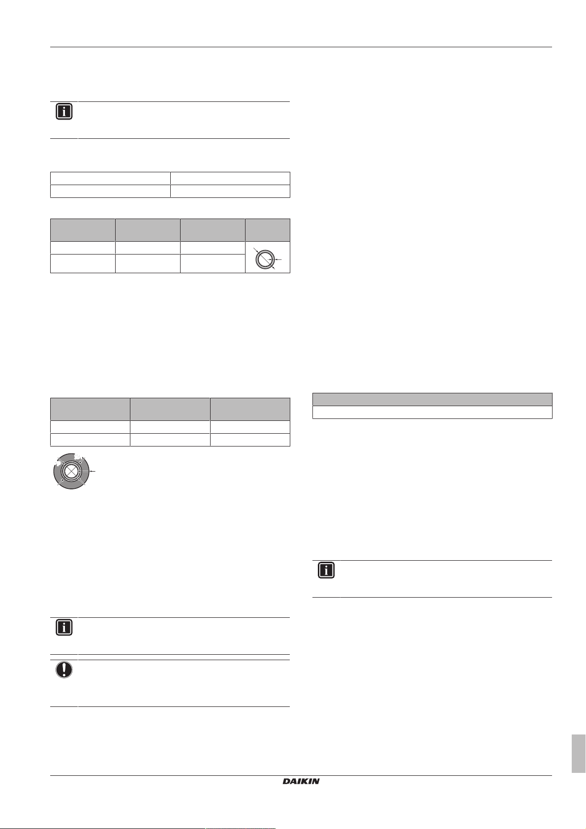
6 Preparation
t
Ø
ØiØ
i
t
ØpØ
p
6.3 Preparing refrigerant piping
6.3.1 Refrigerant piping requirements
INFORMATION
Also read the precautions and requirements in the
"General safety precautions" chapter.
▪ Piping material: Phosphoric acid deoxidised seamless copper.
▪ Piping diameter:
Liquid piping Ø6.4mm (1/4")
Gas piping Ø15.9mm (5/8")
▪ Piping temper grade and thickness:
Outer diameter
(Ø)
6.4mm (1/4") Annealed (O) ≥0.8mm
15.9mm (5/8") Annealed (O) ≥1.0mm
(a) Depending on the applicable legislation and the unit's
Temper grade Thickness (t)
maximum working pressure (see "PS High" on the unit
name plate), larger piping thickness might be required.
(a)
6.3.2 Refrigerant piping insulation
▪ Use polyethylene foam as insulation material:
▪ with a heat transfer rate between 0.041 and 0.052W/mK (0.035
and 0.045kcal/mh°C)
▪ with a heat resistance of at least 120°C
▪ Insulation thickness
Pipe outer diameter
(Øp)
6.4mm (1/4") 8~10mm 10mm
15.9mm (5/8") 16~20mm 13mm
If the temperature is higher than 30°C and the humidity is higher
than RH 80%, the thickness of the insulation materials should be at
least 20 mm to prevent condensation on the surface of the
insulation.
Insulation inner
diameter (Øi)
Insulation thickness
(t)
6.4 Preparing water piping
▪ Valve towards expansion vessel. The valve towards the
expansion vessel (if equipped) MUST be open.
6.4.1 Water circuit requirements
▪ Connecting piping – Force. Do NOT use excessive force when
connecting the piping. Deformation of the piping can cause
malfunctioning of the unit.
▪ Connecting piping – Tools. Only use appropriate tooling to
handle brass, which is a soft material. If NOT, pipes will get
damaged.
▪ Connecting piping – Air, moisture, dust. If air, moisture or dust
gets into the circuit, problems may occur. To prevent this:
▪ Only use clean pipes
▪ Hold the pipe end downwards when removing burrs.
▪ Cover the pipe end when inserting it through a wall, to prevent
dust and/or particles entering the pipe.
▪ Use a decent thread sealant to seal connections.
▪ Closed circuit. Use the indoor unit ONLY in a closed water
system. Using the system in an open water system will lead to
excessive corrosion.
▪ Glycol. For safety reasons, it is NOT allowed to add any kind of
glycol to the water circuit.
▪ Piping length. It is recommended to avoid long runs of piping
between the domestic hot water tank and the hot water end point
(shower, bath,…) and to avoid dead ends.
▪ Piping diameter. Select the water piping diameter in relation to
the required water flow and the available external static pressure
of the pump. See "14 Technical data"on page88 for the external
static pressure curves of the indoor unit.
▪ Water flow. You can find the minimum required water flow for
indoor unit operation in the following table. In all cases, this flow
needs to be guaranteed. When the flow is lower, the indoor unit
will stop operation and display error 7H.
Minimum required flow rate
12l/min
▪ Field supply components – Water. Only use materials that are
compatible with water used in the system and with the materials
used in the indoor unit.
▪ Field supply components – Water pressure and temperature.
Check that all components in the field piping can withstand the
water pressure and water temperature.
▪ Water pressure. The maximum water pressure is 4 bar. Provide
adequate safeguards in the water circuit to ensure that the
maximum pressure is NOT exceeded.
▪ Water temperature. All installed piping and piping accessories
(valve, connections,…) MUST withstand the following
temperatures:
INFORMATION
The following illustration is an example and might NOT
match your system layout.
INFORMATION
Also read the precautions and requirements in the
"General safety precautions" chapter.
NOTICE
In case of plastic pipes, make sure they are fully oxygen
diffusion tight according to DIN 4726. The diffusion of
oxygen into the piping can lead to excessive corrosion.
▪ Connecting piping – Legislation. Make all piping connections in
accordance with the applicable legislation and the instructions in
the "Installation" chapter, respecting the water inlet and outlet.
ERGA04~08DAV3(A) + EHVH04+08S23DAV
Daikin Altherma – Low temperature split
4P499573-1A – 2018.11
Installer reference guide
25
Page 26
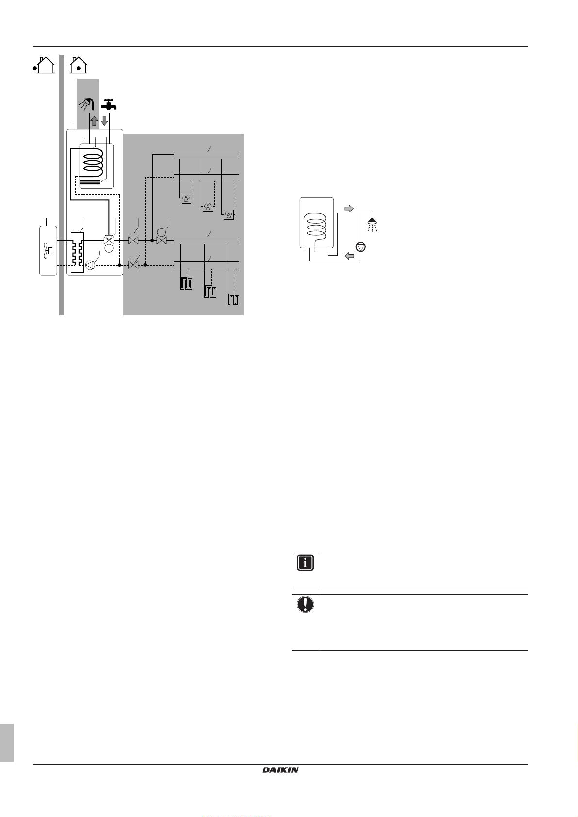
6 Preparation
M
M
FCU1
FCU2
FCU3
FHL1
FHL2
FHL3
a
b
c
e f
g f h
i
i
i
i
j dk
89°C
75°C
c
d
a b
a Outdoor unit
b Indoor unit
c Heat exchanger
d Anti-legionella heater
e Pump
f Stop valve
g Motorised 3-way valve
h Motorised 2-way valve (field supply)
i Collector
j Domestic hot water tank
k Heat exchanger coil
FCU1...3 Fan coil unit (optional) (field supply)
FHL1...3 Floor heating loop (field supply)
▪ Drainage – Low points. Provide drain taps at all low points of the
system in order to allow complete drainage of the water circuit.
▪ Drainage – Pressure relief valve. Connect the drain hose
properly to the drain to avoid water dripping out of the unit. See
"7.4.4To connect the drain hose to the drain"on page34.
▪ Air vents. Provide air vents at all high points of the system, which
must also be easily accessible for servicing. Two automatic air
purges are provided in the indoor unit. Check that the air purges
are NOT tightened too much, so that automatic release of air in
the water circuit is possible.
▪ Zn-coated parts. Never use Zn-coated parts in the water circuit.
Because the unit's internal water circuit uses copper piping,
excessive corrosion may occur.
▪ Non-brass metallic piping. When using non-brass metallic
piping, insulate the brass and non-brass properly so that they do
NOT make contact with each other. This to prevent galvanic
corrosion.
▪ Valve – Change‑over time. When using a 2-way valve or a 3-way
valve in the water circuit, the maximum change-over time of the
valve must be 60seconds.
▪ Domestic hot water tank – Capacity. To avoid stagnation of
water, it is important that the storage capacity of the domestic hot
water tank meets the daily consumption of domestic hot water.
▪ Domestic hot water tank – After installation. Immediately after
installation, the domestic hot water tank must be flushed with fresh
water. This procedure must be repeated at least once a day the
first 5 consecutive days after installation.
▪ Domestic hot water tank – Standstills. In cases where during
longer periods of time there is no consumption of hot water, the
equipment MUST be flushed with fresh water before usage.
▪ Domestic hot water tank – Disinfection. For the disinfection
function of the domestic hot water tank, see "8.4.6 Tank" on
page60.
▪ Thermostatic mixing valves. In accordance with the applicable
legislation, it may be necessary to install thermostatic mixing
valves.
▪ Hygienic measures. The installation must be in compliance with
the applicable legislation and may require additional hygienic
installation measures.
▪ Recirculation pump. In accordance with the applicable
legislation, it may be required to connect a recirculation pump in
between the hot water end point and the recirculation connection
of the domestic hot water tank.
a Recirculation connection
b Hot water connection
c Shower
d Recirculation pump
▪ Valve towards expansion vessel. The valve towards the
expansion vessel (if equipped) MUST be open.
6.4.2 Formula to calculate the expansion vessel pre-pressure
The pre-pressure (Pg) of the vessel depends on the installation
height difference (H):
Pg=0.3+(H/10) (bar)
6.4.3 To check the water volume and flow rate
The indoor unit has an expansion vessel of 10litre with a factory-set
pre-pressure of 1bar.
To make sure that the unit operates properly:
▪ You must check the minimum and maximum water volume.
▪ You might need to adjust the pre-pressure of the expansion
vessel.
Minimum water volume
Check that the total water volume in the installation is minimum
20litres without backup heater and minimum 10litres with optional
backup heater, the internal water volume of the indoor unit NOT
included.
INFORMATION
In critical processes, or in rooms with a high heat load,
extra water might be required.
NOTICE
When circulation in each space heating/cooling loop is
controlled by remotely controlled valves, it is important that
the minimum water volume is guaranteed, even if all of the
valves are closed.
Installer reference guide
26
ERGA04~08DAV3(A) + EHVH04+08S23DAV
Daikin Altherma – Low temperature split
4P499573-1A – 2018.11
Page 27
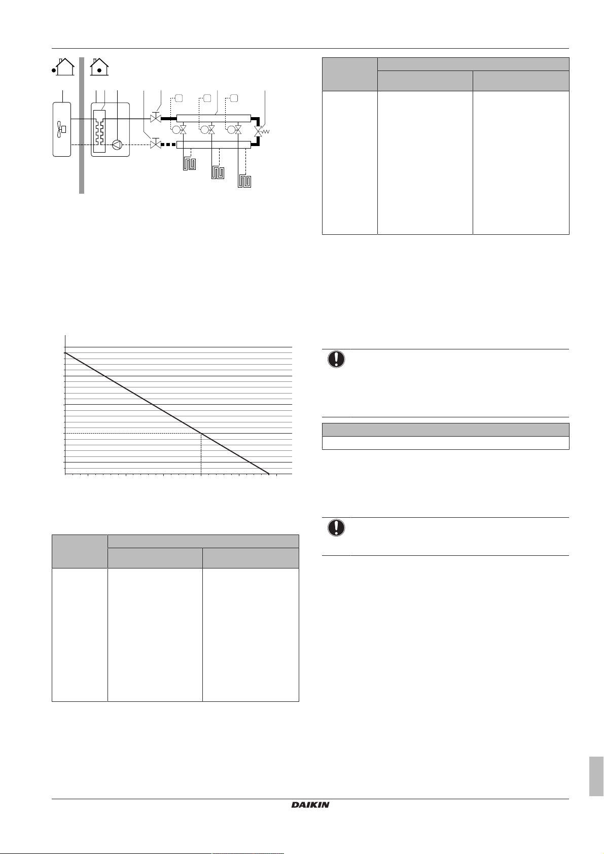
6 Preparation
FHL1
FHL2
FHL3
M1
T1
M2T2M3
T3
eea db f gc
0.3
0.5
1
1.5
2
2.4
5020 100 150 200 250 290
a
b
a Outdoor unit
b Indoor unit
c Heat exchanger
d Pump
e Shut-off valve
f Collector (field supply)
g Overpressure bypass valve (delivered as accessory)
FHL1...3 Floor heating loop (field supply)
T1...3 Individual room thermostat (optional)
M1...3 Individual motorised valve to control loop FHL1...3 (field
supply)
Maximum water volume
Use the following graph to determine the maximum water volume for
the calculated pre-pressure.
Installation
height
difference
(a)
≤200l >200l
>7m Do the following:
▪ Increase the pre-
pressure according to
the required
installation height
difference. The prepressure should
Water volume
The expansion vessel of
the indoor unit is too
small for the installation.
In this case, it is
recommended to install
an extra vessel outside
the unit.
increase by 0.1 bar for
each metre above 7 m.
▪ Check if the water
volume does NOT
exceed the maximum
allowed water volume.
(a) This is the height difference (m) between the highest point
of the water circuit and the indoor unit. If the indoor unit is
at the highest point of the installation, the installation height
is 0m.
Minimum flow rate
Check that the minimum flow rate in the installation is guaranteed in
all conditions. This minimum flow rate is required during defrost/
backup heater operation (if applicable). For this purpose, use the
overpressure bypass valve delivered with the unit, and respect the
minimum water volume.
NOTICE
When circulation in each or certain space heating loops is
controlled by remotely controlled valves, it is important that
the minimum flow rate is guaranteed, even if all valves are
closed. In case the minimum flow rate cannot be reached,
a flow error 7H will be generated (no heating or operation).
Minimum required flow rate
12l/min
See the recommended procedure as described in "9.4 Checklist
during commissioning"on page75.
a Pre-pressure (bar)
b Maximum water volume (l)
6.4.4 Changing the pre-pressure of the expansion vessel
Example: Maximum water volume and expansion vessel prepressure
Installation
height
difference
(a)
≤200l >200l
≤7m No pre-pressure
adjustment is required.
Water volume
Do the following:
▪ Decrease the pre-
pressure according to
the required installation
height difference. The
pre-pressure should
decrease by 0.1 bar for
each metre below 7 m.
NOTICE
Only a licensed installer may adjust the pre-pressure of the
expansion vessel.
When changing the default pre-pressure of the expansion vessel
(1bar) is required, take following guidelines into account:
▪ Only use dry nitrogen to set the expansion vessel pre-pressure.
▪ Inappropriate setting of the expansion vessel pre-pressure will
lead to malfunction of the system.
Changing the pre-pressure of the expansion vessel should be done
by releasing or increasing nitrogen pressure through the Schrader
valve of the expansion vessel.
▪ Check if the water
volume does NOT
exceed the maximum
allowed water volume.
ERGA04~08DAV3(A) + EHVH04+08S23DAV
Daikin Altherma – Low temperature split
4P499573-1A – 2018.11
Installer reference guide
27
Page 28
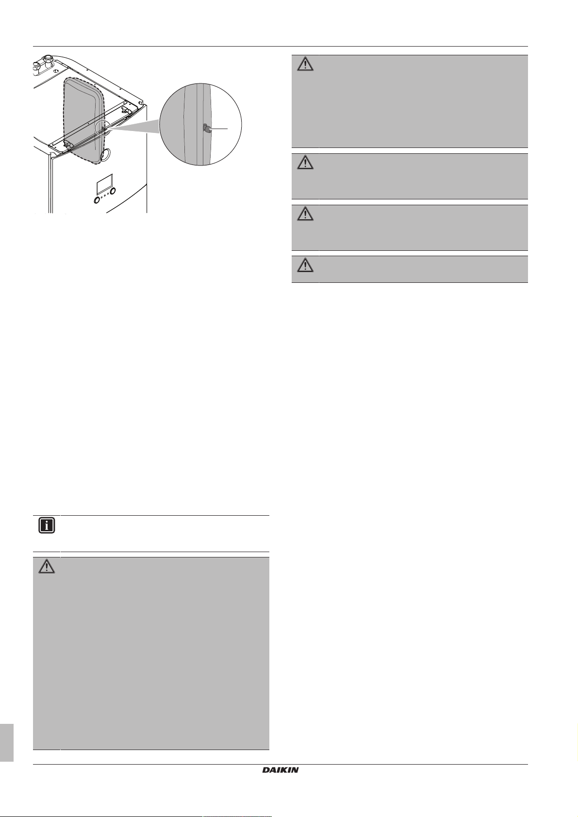
6 Preparation
a
WARNING
▪ All wiring MUST be performed by an authorised
electrician and MUST comply with the applicable
legislation.
▪ Make electrical connections to the fixed wiring.
▪ All components procured on-site and all electrical
construction MUST comply with the applicable
legislation.
WARNING
The backup heater MUST have a dedicated power supply
and MUST be protected by the safety devices required by
the applicable legislation.
a Schrader valve
6.4.5 To check the water volume: Examples
Example 1
The indoor unit is installed 5 m below the highest point in the water
circuit. The total water volume in the water circuit is 100l.
No actions or adjustments are required.
Example 2
The indoor unit is installed at the highest point in the water circuit.
The total water volume in the water circuit is 250l.
Actions:
▪ Because the total water volume (250l) is more than the default
water volume (200l), the pre-pressure must be decreased.
▪ The required pre-pressure is:
Pg = (0.3+(H/10))bar = (0.3+(0/10))bar=0.3bar.
▪ The corresponding maximum water volume at 0.3 bar is 290 l.
(See the graph in the chapter above).
▪ Because 250 l is lower than 290 l, the expansion vessel is
appropriate for the installation.
6.5 Preparing electrical wiring
6.5.1 About preparing electrical wiring
WARNING
The anti-legionella heater MUST have a dedicated power
supply and MUST be protected by the safety devices
required by the applicable legislation.
WARNING
ALWAYS use multicore cable for power supply cables.
6.5.2 About preferential kWh rate power supply
Electricity companies throughout the world work hard to provide
reliable electric service at competitive prices and are often
authorized to bill clients at benefit rates. E.g. time-of-use rates,
seasonal rates, Wärmepumpentarif in Germany and Austria, ...
This equipment allows for connection to such preferential kWh rate
power supply delivery systems.
Consult with the electricity company acting as provider at the site
where this equipment is to be installed to know whether it is
appropriate to connect the equipment in one of the preferential kWh
rate power supply delivery systems available, if any.
When the equipment is connected to such preferential kWh rate
power supply, the electricity company is allowed to:
▪ interrupt power supply to the equipment for certain periods of time;
▪ demand that the equipment only consumes a limited amount of
electricity during certain periods of time.
Whether the power supply is interrupted or not, the wiring to the unit
is different.
INFORMATION
Also read the precautions and requirements in the
"General safety precautions" chapter.
WARNING
▪ If the power supply has a missing or wrong N-phase,
equipment might break down.
▪ Establish proper earthing. Do NOT earth the unit to a
utility pipe, surge absorber, or telephone earth.
Incomplete earthing may cause electrical shock.
▪ Install the required fuses or circuit breakers.
▪ Secure the electrical wiring with cable ties so that the
cables do NOT come in contact with sharp edges or
piping, particularly on the high-pressure side.
▪ Do NOT use taped wires, stranded conductor wires,
extension cords, or connections from a star system.
They can cause overheating, electrical shock or fire.
▪ Do NOT install a phase advancing capacitor, because
this unit is equipped with an inverter. A phase
advancing capacitor will reduce performance and may
cause accidents.
Installer reference guide
28
ERGA04~08DAV3(A) + EHVH04+08S23DAV
Daikin Altherma – Low temperature split
4P499573-1A – 2018.11
Page 29
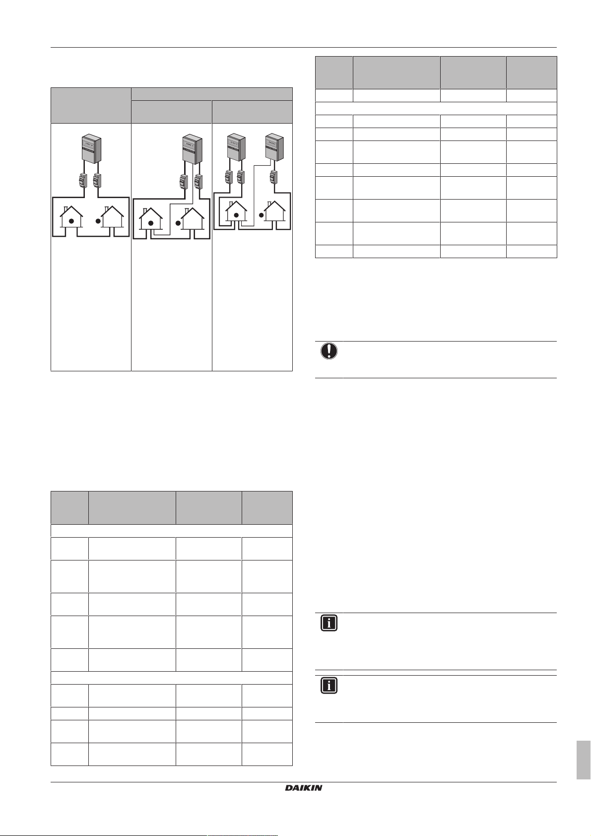
7 Installation
1
5
8
0
1
5
0
0
0
2
a
3
1
4
5
8
0
1
5
0
0
0
2
b
3
5 3
a
b
14
5
8
0
1
5
0
0
0
5
8
0
1
5
0
0
0
2
6.5.3 Overview of electrical connections except external actuators
Normal power
supply
Preferential kWh rate power supply
Power supply is
NOT interrupted
Power supply is
interrupted
Item Description Wires Maximum
running
current
10 Heat pump convector 2 100mA
Field supplied components
11 Shut-off valve 2 100mA
12 Electricity meter 2 (per meter)
13 Domestic hot water
2
(b)
(b)
(b)
(b)
pump
14 Alarm output 2
15 Changeover to external
2
(b)
(b)
heat source control
16 Space cool/heat
2
(b)
operation control
(b)
(d)
During preferential
kWh rate power
supply activation,
power supply is NOT
interrupted. The
outdoor unit is turned
off by the control.
Remark: The
electricity company
must always allow the
power consumption
of the indoor unit.
a Normal power supply
b Preferential kWh rate power supply
1 Power supply for outdoor unit
2 Power supply and interconnection cable to indoor unit
3 Power supply for anti‑legionella heater
4 Preferential kWh rate power supply (voltage free contact)
5 Normal kWh rate power supply (to power the indoor unit
PCB in the event of power supply interruption of the
preferential kWh rate power supply)
kWh rate power
supply activation,
power supply is
interrupted
immediately or after
some time by the
electricity company.
In this case, the
indoor unit must be
powered by a
separate normal
power supply.
During preferential
17 Power consumption
digital inputs
2 (per input
signal)
18 Safety thermostat 2
(a) Refer to name plate on outdoor unit.
(b) Minimum cable section 0.75mm².
(c) Cable section 2.5mm².
(d) Cable section 0.75mm² till 1.25mm²; maximum length:
50m. Voltage-free contact shall ensure the minimum
applicable load of 15VDC, 10mA.
(e) Cable section 0.75mm² till 1.25mm²; maximum length:
500m.
(f) Cable section 1.5mm².
NOTICE
More technical specifications of the different connections
are indicated on the inside of the indoor unit.
7 Installation
7.1 Overview: Installation
This chapter describes what you have to do and know on-site to
6.5.4 Overview of electrical connections for external and internal actuators
Item Description Wires Maximum
Outdoor unit and indoor unit power supply
1 Power supply for
2+GND
outdoor unit
2 Power supply and
3
interconnection cable to
indoor unit
3 Power supply for anti-
2+GND
legionella heater
4 Preferential kWh rate
2
power supply (voltage
free contact)
5 Normal kWh rate power
2 6.3A
supply
Optional equipment
6 User interface used as
2
room thermostat
7 Room thermostat 3 or 4 100mA
8 Outdoor ambient
9 Indoor ambient
temperature sensor
2
2
running
current
(a)
(f)
(c)
(d)
(e)
(b)
(b)
(b)
install the system.
Typical workflow
Installation typically consists of the following stages:
1 Mounting the outdoor unit.
2 Mounting the indoor unit.
3 Connecting the refrigerant piping.
4 Checking the refrigerant piping.
5 Charging refrigerant.
6 Connecting the water piping.
7 Connecting the electrical wiring.
8 Finishing the outdoor installation.
9 Finishing the indoor installation.
INFORMATION
If you have limited installation space, do the following
before installing the unit in its final position: "7.4.4 To
connect the drain hose to the drain" on page 34. It
requires to remove one or both side panels.
INFORMATION
Depending on the units and/or the installation conditions, it
might be necessary to connect electrical wiring before you
can charge refrigerant.
temperature sensor
ERGA04~08DAV3(A) + EHVH04+08S23DAV
Daikin Altherma – Low temperature split
4P499573-1A – 2018.11
Installer reference guide
29
Page 30
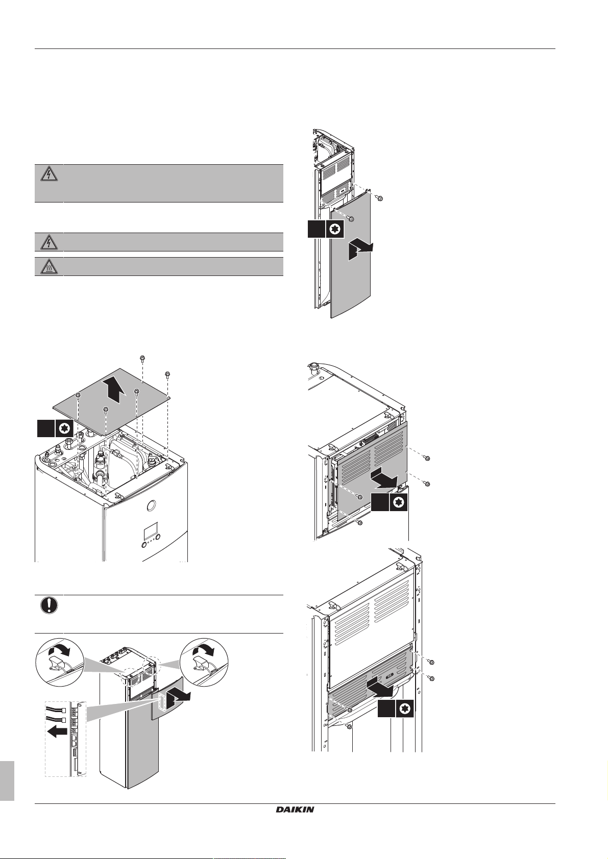
7 Installation
5×
T25
2
1
1
3
2×
T25
4×
T25
4×
T25
7.2 Opening the units
7.2.1 About opening the units
At certain times, you have to open the unit. Example:
▪ When connecting the refrigerant piping
▪ When connecting the electrical wiring
▪ When maintaining or servicing the unit
DANGER: RISK OF ELECTROCUTION
Do NOT leave the unit unattended when the service cover
is removed.
7.2.2 To open the outdoor unit
DANGER: RISK OF ELECTROCUTION
DANGER: RISK OF BURNING
See "7.5.8To connect the refrigerant piping to the outdoor unit" on
page 37 and "7.9.6 To connect the electrical wiring on the outdoor
unit"on page42.
7.2.3 To open the indoor unit
1 Remove the top panel.
3 If necessary, remove the front plate. This is, for example,
necessary in the following cases:
▪ "7.2.5 To lower the switch box on the indoor unit" on
page31
▪ "7.4.4To connect the drain hose to the drain"on page34
▪ When you need access to the high voltage switch box
7.2.4 To open the switch box cover of the indoor unit
2 Remove the user interface panel. Open the hinges at the top
Installer reference guide
30
and slide the top panel upwards.
NOTICE
If you remove the user interface panel, also disconnect the
cables from the back of the panel to prevent damage.
ERGA04~08DAV3(A) + EHVH04+08S23DAV
Daikin Altherma – Low temperature split
4P499573-1A – 2018.11
Page 31

7 Installation
1
2
2×
T25
3
3
a
b
c
(mm)
0 mm
<150
a
>300
300
600
>100
7.2.5 To lower the switch box on the indoor unit
During the installation, you will need access to the inside of the
indoor unit. To have easier front access, put the switch box lower on
the unit as follows:
Prerequisite: The user interface panel and front panel have been
removed.
1 Remove the top panel that keeps the switch box into place at
the top of the unit.
2 Tilt the switch box to the front and lift it out of its hinges.
3 Place the switch box lower on the unit. Use the 2 hinges located
lower on the unit.
7.3.2 Precautions when mounting the outdoor unit
INFORMATION
Also read the precautions and requirements in the
following chapters:
▪ General safety precautions
▪ Preparation
7.3.3 To provide the installation structure
Check the strength and level of the installation ground so that the
unit will not cause any operating vibration or noise.
Fix the unit securely by means of foundation bolts in accordance
with the foundation drawing.
This topic shows different installation structures. For all, use 4 sets
of M8 or M10 anchor bolts, nuts and washers. In any case, provide
at least 300 mm of free space below the unit. Additionally, make
sure the unit is positioned at least 100 mm above the maximum
expected level of snow.
INFORMATION
The maximum height of the upper protruding part of the
bolts is 15mm.
INFORMATION
If you install the U-beams in combination with the low
sound cover (EKLN08A1), different installation instructions
apply for the U-beams. See the installation manual of the
low sound cover.
7.3 Mounting the outdoor unit
7.3.1 About mounting the outdoor unit
When
You have to mount the outdoor and indoor unit before you can
connect the refrigerant and water piping.
Typical workflow
Mounting the outdoor unit typically consists of the following stages:
1 Providing the installation structure.
2 Installing the outdoor unit.
3 Providing drainage.
4 Preventing the unit from falling over.
5 Protecting the unit against snow and wind by installing a snow
ERGA04~08DAV3(A) + EHVH04+08S23DAV
Daikin Altherma – Low temperature split
4P499573-1A – 2018.11
cover and baffle plates. See "Preparing installation site" in
"6Preparation"on page21.
a Low sound cover
b Bottom parts of the low sound cover
c U-beams
Option 1: On mounting feet "flexi-foot with strut"
a Maximum snowfall height
Installer reference guide
31
Page 32

7 Installation
0 mm
300
600
<150
<150
(mm)
>300
100
a
b
0 mm
>250
>300
>250
(mm)
a
b
c
4×
Option 2: On plastic mounting feet
In this case, you can use the bolts, nuts, washers and spring
washers delivered with the unit as accessories.
Option 3: On a pedestal with the EKFT008D option kit
The EKFT008D option kit is recommended in areas with heavy
snowfall.
a Maximum snowfall height
b EKFT008D option kit
Option 4: On brackets to the wall with the EKFT008D option kit
The EKFT008D option kit is recommended in areas with heavy
snowfall.
Installer reference guide
32
a Maximum snowfall height
b EKFT008D option kit
c Anti-vibration rubber (field supply)
7.3.4 To install the outdoor unit
CAUTION
Do NOT remove the protective cardboard before the unit is
installed properly.
1 Lift the outdoor unit as described in "3.2.2 To handle the
outdoor unit"on page7.
2 Install the outdoor unit as follows:
▪ (1) Put the unit into position (using the sling to the left and
the handle to the right).
▪ (2) Remove the sling (by pulling 1 side of the sling).
▪ (3) Fix the unit.
ERGA04~08DAV3(A) + EHVH04+08S23DAV
Daikin Altherma – Low temperature split
4P499573-1A – 2018.11
Page 33

7 Installation
2×
3
2
1
a a
a
b
b
a
c
355 mm
600 mm
a Air outlet
NOTICE
Properly align the unit. Make sure the backside of the unit
does NOT protrude.
3 Remove the protective cardboard and instruction sheet.
a Protective cardboard
b Instruction sheet
7.3.5 To provide drainage
▪ Make sure that condensation water can be evacuated properly.
▪ Install the unit on a base to make sure that there is proper
drainage in order to avoid ice accumulation.
▪ Prepare a water drainage channel around the foundation to drain
waste water away from the unit.
▪ Avoid drain water flowing over the footpath, so that it does NOT
become slippery in case of ambient freezing temperatures.
▪ If you install the unit on a frame, install a waterproof plate within
150 mm of the bottom side of the unit in order to prevent water
from getting into the unit and to avoid drain water dripping (see the
following figure).
a Drain pan
b U-beams
c Drain hole insulation
▪ Drain pan heater. You can use the drain pan heater option
(EKDPH008CA) to prevent freezing-up of the drain pan. For the
installation instructions, see the installation manual of the drain
pan heater.
▪ Non-heated drain tube. When using the drain pan heater without
drain tube or with a non-heated drain tube, remove the drain hole
insulation (Item c on the illustration).
NOTICE
If the drain holes of the outdoor unit are blocked up,
provide space of at least 300mm below the outdoor unit.
▪ Drain pan. You can use the drain pan option (EKDP008D) to
gather the drain water. For the complete installation instructions,
see the installation manual of the drain pan. In short, the drain pan
must be installed level (with a tolerance of 1° at all sides) and as
follows:
ERGA04~08DAV3(A) + EHVH04+08S23DAV
Daikin Altherma – Low temperature split
4P499573-1A – 2018.11
Installer reference guide
33
Page 34

7 Installation
a
b
d
c
c
b
≤1°
0°
1° 1°
INFORMATION
If you install the drain pan kit (with or without drain pan
heater) in combination with the low sound cover
(EKLN08A1), different installation instructions apply for the
drain pan kit. See the installation manual of the low sound
cover.
a Low sound cover
b Bottom parts of the low sound cover
c Drain pan kit
d Drain pan heater
7.3.6 To prevent the outdoor unit from falling over
In case the unit is installed in places where strong wind can tilt the
unit, take following measure:
1 Prepare 2 cables as indicated in the following illustration (field
supply).
2 Place the 2 cables over the outdoor unit.
3 Insert a rubber sheet between the cables and the outdoor unit
to prevent the cables from scratching the paint (field supply).
4 Attach the ends of the cables and tighten them.
7.4 Mounting the indoor unit
7.4.1 About mounting the indoor unit
When
You have to mount the outdoor and indoor unit before you can
connect the refrigerant and water piping.
Typical workflow
Mounting the indoor unit typically consists of the following stages:
1 Installing the indoor unit.
7.4.2 Precautions when mounting the indoor unit
INFORMATION
Also read the precautions and requirements in the
following chapters:
▪ General safety precautions
▪ Preparation
7.4.3 To install the indoor unit
1 Lift the indoor unit from the pallet and place it on the floor. Also
see "3.3.3To handle the indoor unit"on page8.
2 Connect the drain hose to the drain. See "7.4.4To connect the
drain hose to the drain"on page34.
3 Slide the indoor unit into position.
4 Adjust the height of the leveling feet to compensate for floor
irregularities. The maximum allowed deviation is 1°.
NOTICE
Do NOT tilt the unit forwards:
7.4.4 To connect the drain hose to the drain
Installer reference guide
34
Water coming from the pressure relief valve is collected in the drain
pan. The drain pan is connected to a drain hose inside the unit. You
must connect the drain hose to an appropriate drain according to the
applicable legislation. You can route the drain hose through the left
or right side panel.
Prerequisite: The user interface panel and front panel have been
removed.
ERGA04~08DAV3(A) + EHVH04+08S23DAV
Daikin Altherma – Low temperature split
4P499573-1A – 2018.11
Page 35

7 Installation
1
3×
T25
3
2
1
3×
T25
3
2
1 Remove one of the side panels.
2 Cut out the rubber grommet.
3 Pull the drain hose through the hole.
4 Reattach the side panel. Ensure the water can flow through the
drain tube.
It is recommended to use a tundish to collect the water.
Option 1: Through the left side panel
Option 2: Through the right side panel
▪ Keeping in mind the guidelines for:
▪ Pipe bending
▪ Flaring pipe ends
▪ Brazing
▪ Using the stop valves
7.5.2 Precautions when connecting the refrigerant piping
INFORMATION
Also read the precautions and requirements in the
following chapters:
▪ General safety precautions
▪ Preparation
DANGER: RISK OF BURNING
CAUTION
▪ Do NOT use mineral oil on flared part.
▪ Do NOT reuse piping from previous installations.
▪ NEVER install a drier to this R32 unit to guarantee its
lifetime. The drying material may dissolve and damage
the system.
NOTICE
Take the following precautions on refrigerant piping into
account:
▪ Avoid anything but the designated refrigerant to get
mixed into the refrigerant cycle (e.g. air).
▪ Only use R32 when adding refrigerant.
▪ Only use installation tools (e.g. manifold gauge set) that
are exclusively used for R32 installations to withstand
the pressure and to prevent foreign materials (e.g.
mineral oils and moisture) from mixing into the system.
▪ Install the piping so that the flare is NOT subjected to
mechanical stress.
▪ Protect the piping as described in the following table to
prevent dirt, liquid or dust from entering the piping.
▪ Use caution when passing copper tubes through walls
(see figure below).
7.5 Connecting the refrigerant piping
7.5.1 About connecting the refrigerant piping
Before connecting the refrigerant piping
Make sure the outdoor and indoor unit are mounted.
Typical workflow
Connecting the refrigerant piping involves:
▪ Connecting the refrigerant piping to the outdoor unit
▪ Connecting the refrigerant piping to the indoor unit
▪ Insulating the refrigerant piping
ERGA04~08DAV3(A) + EHVH04+08S23DAV
Daikin Altherma – Low temperature split
4P499573-1A – 2018.11
Outdoor unit >1month Pinch the pipe
Indoor unit Regardless of the
Unit Installation period Protection method
<1month Pinch or tape the pipe
period
INFORMATION
Do NOT open the refrigerant stop valve before checking
the refrigerant piping. When you need to charge additional
refrigerant it is recommended to open the refrigerant stop
valve after charging.
Installer reference guide
35
Page 36

7 Installation
a b
c
d
R=0.4~0.8
45°
±2
90°
±2
A
a b
A
a b
c
a b c d e
f
f
c
d
a
b
7.5.3 Guidelines when connecting the refrigerant piping
Take the following guidelines into account when connecting pipes:
▪ Coat the flare inner surface with ether oil or ester oil when
connecting a flare nut. Tighten 3 or 4 turns by hand, before
tightening firmly.
▪ ALWAYS use 2 wrenches together when loosening a flare nut.
▪ ALWAYS use a spanner and torque wrench together to tighten the
flare nut when connecting the piping. This to prevent nut cracking
and leaks.
a Torque wrench
b Spanner
c Piping union
d Flare nut
Piping size
(mm)
Tightening
torque (N•m)
Flare
dimensions (A)
Flare shape
(mm)
(mm)
Ø6.4 15~17 8.7~9.1
Ø15.9 63~75 19.3~19.7
7.5.4 Pipe bending guidelines
Use a pipe bender for bending. All pipe bends should be as gentle
as possible (bending radius should be 30~40mm or larger).
7.5.5 To flare the pipe end
CAUTION
▪ Incomplete flaring may cause refrigerant gas leakage.
▪ Do NOT re-use flares. Use new flares to prevent
refrigerant gas leakage.
▪ Use flare nuts that are included with the unit. Using
different flare nuts may cause refrigerant gas leakage.
1 Cut the pipe end with a pipe cutter.
2 Remove burrs with the cut surface facing down so that the
chips do NOT enter the pipe.
Flare tool for R32
(clutch type)
Conventional flare tool
Clutch type
(Ridgid-type)
Wing nut type
(Imperial-type)
A 0~0.5mm 1.0~1.5mm 1.5~2.0mm
5 Check that the flaring is properly made.
a Flare’s inner surface MUST be flawless.
b The pipe end MUST be evenly flared in a perfect circle.
c Make sure the flare nut is fitted.
7.5.6 To braze the pipe end
The indoor unit and outdoor unit have flare connections. Connect
both ends without brazing. If brazing should be needed, take the
following into account:
▪ When brazing, blow through with nitrogen to prevent creation of
large quantities of oxidised film on the inside of the piping. This
film adversely affects valves and compressors in the refrigerating
system and prevents proper operation.
▪ Set the nitrogen pressure to 20kPa (0.2bar) (just enough so it
can be felt on the skin) with a pressure-reducing valve.
a Refrigerant piping
b Part to be brazed
c Taping
d Manual valve
e Pressure-reducing valve
f Nitrogen
▪ Do NOT use anti-oxidants when brazing pipe joints.
Residue can clog pipes and break equipment.
▪ Do NOT use flux when brazing copper-to-copper refrigerant
piping. Use phosphor copper brazing filler alloy (BCuP), which
does not require flux.
Flux has an extremely harmful influence on refrigerant piping
systems. For instance, if chlorine based flux is used, it will cause
pipe corrosion or, in particular, if the flux contains fluorine, it will
deteriorate the refrigerant oil.
7.5.7 Using the stop valve and service port
To handle the stop valve
Take the following guidelines into account:
▪ The stop valves are factory closed.
▪ The following figure shows the stop valve parts required when
handling the valve.
a Cut exactly at right angles.
b Remove burrs.
3 Remove the flare nut from the stop valve and put the flare nut
on the pipe.
4 Flare the pipe. Set exactly at the position as shown in the
following figure.
Installer reference guide
36
a Service port and service port cap
b Valve stem
c Field piping connection
d Stem cap
▪ Keep both stop valves open during operation.
ERGA04~08DAV3(A) + EHVH04+08S23DAV
Daikin Altherma – Low temperature split
4P499573-1A – 2018.11
Page 37

7 Installation
a
b
1×
a
b
c
b
a
▪ Do NOT apply excessive force to the valve stem. Doing so may
break the valve body.
▪ ALWAYS make sure to secure the stop valve with a spanner, then
loosen or tighten the flare nut with a torque wrench. Do NOT place
the spanner on the stem cap, as this could cause a refrigerant
leak.
a Spanner
b Torque wrench
▪ When it is expected that the operating pressure will be low (e.g.
when cooling will be performed while the outside air temperature
is low), sufficiently seal the flare nut in the stop valve on the gas
line with silicon sealant to prevent freezing.
Silicon sealant; make sure there is no gap.
To open/close the stop valve
1 Remove the stop valve cover.
2 Insert a hexagon wrench (liquid side: 4mm, gas side: 4mm)
into the valve stem and turn the valve stem:
Item Tightening torque (N∙m)
Service port cap 11.5~13.9
7.5.8 To connect the refrigerant piping to the outdoor unit
1 Connect the liquid refrigerant connection from the indoor unit to
the liquid stop valve of the outdoor unit.
a Liquid stop valve
b Gas stop valve
c Service port
2 Connect the gas refrigerant connection from the indoor unit to
the gas stop valve of the outdoor unit.
NOTICE
It is recommended that the refrigerant piping between
Counterclockwise to open.
Clockwise to close.
3 When the stop valve CANNOT be turned any further, stop
turning.
4 Install the stop valve cover.
Result: The valve is now open/closed.
indoor and outdoor unit is installed in a ducting or the
refrigerant piping is wrapped with finishing tape.
7.5.9 To connect the refrigerant piping to the indoor unit
1 Connect the liquid stop valve from the outdoor unit to the
refrigerant liquid connection of the indoor unit.
To handle the stem cap
▪ The stem cap is sealed where indicated with the arrow. Do NOT
damage it.
▪ After handling the stop valve, tighten the stem cap, and check for
refrigerant leaks.
Item Tightening torque (N∙m)
Stem cap, liquid side 13.5~16.5
Stem cap, gas side 22.5~27.5
2 Connect the gas stop valve from the outdoor unit to the
To handle the service cap
▪ ALWAYS use a charge hose equipped with a valve depressor pin,
since the service port is a Schrader type valve.
▪ After handling the service port, tighten the service port cap, and
check for refrigerant leaks.
a Refrigerant liquid connection
b Refrigerant gas connection
refrigerant gas connection of the indoor unit.
NOTICE
It is recommended that the refrigerant piping between
indoor and outdoor unit is installed in a ducting or the
refrigerant piping is wrapped with finishing tape.
ERGA04~08DAV3(A) + EHVH04+08S23DAV
Daikin Altherma – Low temperature split
4P499573-1A – 2018.11
Installer reference guide
37
Page 38

7 Installation
a d
j
b
f
e
c
g h i
h
INFORMATION
When the indoor unit is installed in a place with limited
space, an optional pipe bend (EKHVTC) kit can be
installed to facilitate the connection to the refrigerant gas
and liquid connections of the indoor unit. For installation
instructions, see the instruction sheet of the pipe bend kit.
7.6 Checking the refrigerant piping
7.6.1 About checking the refrigerant piping
The outdoor unit's internal refrigerant piping has been factory tested
for leaks. You only have to check the outdoor unit's external
refrigerant piping.
Before checking the refrigerant piping
Make sure the refrigerant piping is connected between the outdoor
unit and the indoor unit.
Typical workflow
Checking the refrigerant piping typically consists of the following
stages:
1 Checking for leaks in the refrigerant piping.
2 Performing vacuum drying to remove all moisture, air or
nitrogen from the refrigerant piping.
If there is a possibility of moisture being present in the refrigerant
piping (for example, water may have entered the piping), first carry
out the vacuum drying procedure below until all moisture has been
removed.
NOTICE
Make sure to use a recommended bubble test solution
from your wholesaler. Do not use soap water, which may
cause cracking of flare nuts (soap water may contain salt,
which absorbs moisture that will freeze when the piping
gets cold), and/or lead to corrosion of flared joints (soap
water may contain ammonia which causes a corrosive
effect between the brass flare nut and the copper flare).
1 Charge the system with nitrogen gas up to a gauge pressure of
at least 200 kPa (2 bar). It is recommended to pressurize to
3000kPa (30bar) in order to detect small leaks.
2 Check for leaks by applying the bubble test solution to all
connections.
3 Discharge all nitrogen gas.
7.6.4 To perform vacuum drying
Connect the vacuum pump and manifold as follows:
7.6.2 Precautions when checking the refrigerant piping
INFORMATION
Also read the precautions and requirements in the
following chapters:
▪ General safety precautions
▪ Preparation
NOTICE
Use a 2-stage vacuum pump with a non-return valve that
can evacuate to a gauge pressure of −100.7 kPa
(−1.007 bar)(5 Torr absolute). Make sure the pump oil
does not flow oppositely into the system while the pump is
not working.
NOTICE
Use this vacuum pump for R32 exclusively. Using the
same pump for other refrigerants may damage the pump
and the unit.
NOTICE
▪ Connect the vacuum pump to the service port of the
gas stop valve.
▪ Make sure that the gas stop valve and liquid stop valve
are firmly closed before performing the leak test or
vacuum drying.
a Pressure meter
b Gauge manifold
c Low-pressure valve (Lo)
d High-pressure valve (Hi)
e Charging hoses
f Vacuum pump
g Service port
h Valve lids
i Gas stop valve
j Liquid stop valve
1 Vacuum the system until the pressure on the manifold indicates
−0.1MPa (−1bar).
2 Leave as is for 4-5minutes and check the pressure:
If the pressure… Then…
Does not change There is no moisture in the
system. This procedure is
finished.
Increases There is moisture in the
system. Go to the next step.
3 Vacuum the system for at least 2 hours to a manifold pressure
of −0.1MPa (−1bar).
4 After turning the pump OFF, check the pressure for at least
1hour.
5 If you do NOT reach the target vacuum or CANNOT maintain
the vacuum for 1hour, do the following:
▪ Check for leaks again.
▪ Perform vacuum drying again.
7.6.3 To check for leaks
NOTICE
Do NOT exceed the unit's maximum working pressure (see
"PS High" on the unit name plate).
Installer reference guide
38
NOTICE
Make sure to open the stop valves after installing the
refrigerant piping and performing vacuum drying. Running
the system with the stop valves closed may break the
compressor.
ERGA04~08DAV3(A) + EHVH04+08S23DAV
Daikin Altherma – Low temperature split
4P499573-1A – 2018.11
Page 39

7 Installation
INFORMATION
After opening the stop valve, it is possible that the pressure
in the refrigerant piping does NOT increase. This might be
caused by e.g. the closed state of the expansion valve in
the outdoor unit circuit, but does NOT present any problem
for correct operation of the unit.
7.7 Charging refrigerant
7.7.1 About charging refrigerant
The outdoor unit is factory charged with refrigerant, but in some
cases the following might be necessary:
What When
Charging additional refrigerant When the total liquid piping
length is more than specified
(see later).
Completely recharging refrigerant Example:
▪ When relocating the system.
▪ After a leak.
Charging additional refrigerant
Before charging additional refrigerant, make sure the outdoor unit's
external refrigerant piping is checked (leak test, vacuum drying).
INFORMATION
Depending on the units and/or the installation conditions, it
might be necessary to connect electrical wiring before you
can charge refrigerant.
Typical workflow – Charging additional refrigerant typically consists
of the following stages:
1 Determining if and how much you have to charge additionally.
2 If necessary, charging additional refrigerant.
3 Filling in the fluorinated greenhouse gases label, and fixing it to
the inside of the outdoor unit.
7.7.2 Precautions when charging refrigerant
INFORMATION
Also read the precautions and requirements in the
following chapters:
▪ General safety precautions
▪ Preparation
7.7.3 To determine the additional refrigerant amount
WARNING
If the total refrigerant charge in the system is ≥1.84 kg
(i.e. if the piping length is ≥27 m), you need to comply
with the minimum floor area requirements for the indoor
unit. For more information, see "6.2.3 Installation site
requirements of the indoor unit"on page23.
If the total liquid
piping length is…
≤10m Do NOT add additional refrigerant.
>10m R=(total length (m) of liquid
piping–10m)×0.020
R=Additional charge (kg) (rounded in units
of 0.01kg)
INFORMATION
Piping length is the one-way length of liquid piping.
Then…
7.7.4 To determine the complete recharge amount
INFORMATION
If a complete recharge is necessary, the total refrigerant
charge is: the factory refrigerant charge (see unit name
plate) + the determined additional amount.
Completely recharging refrigerant
Before completely recharging refrigerant, make sure the following is
done:
1 All refrigerant is recovered from the system.
2 The outdoor unit's external refrigerant piping is checked (leak
test, vacuum drying).
3 Vacuum drying on the outdoor unit's internal refrigerant piping is
performed.
NOTICE
Before completely recharging, perform vacuum drying on
the outdoor unit's internal refrigerant piping as well.
Typical workflow – Completely recharging refrigerant typically
consists of the following stages:
1 Determining how much refrigerant to charge.
2 Charging refrigerant.
3 Filling in the fluorinated greenhouse gases label, and fixing it to
the inside of the outdoor unit.
7.7.5 To charge additional refrigerant
WARNING
▪ Only use R32 as refrigerant. Other substances may
cause explosions and accidents.
▪ R32 contains fluorinated greenhouse gases. Its global
warming potential (GWP) value is 675. Do NOT vent
these gases into the atmosphere.
▪ When charging refrigerant, ALWAYS use protective
gloves and safety glasses.
CAUTION
To avoid compressor breakdown, do NOT charge more
than the specified amount of refrigerant.
Prerequisite: Before charging refrigerant, make sure the refrigerant
piping is connected and checked (leak test and vacuum drying).
1 Connect the refrigerant cylinder to the service port.
2 Charge the additional refrigerant amount.
3 Open the gas stop valve.
If pump down is needed in case of dismantling or relocating the
system, see "13.2To pump down"on page86 for more details.
7.7.6 To fix the fluorinated greenhouse gases label
1 Fill in the label as follows:
ERGA04~08DAV3(A) + EHVH04+08S23DAV
Daikin Altherma – Low temperature split
4P499573-1A – 2018.11
Installer reference guide
39
Page 40

7 Installation
b
Contains fluorinated greenhouse gases
2
1
1
1
2
2
kg
tCO2eq
GWP × kg
1000
=
=
+
kg
=
kg
=
GWP: XXX
RXXX
a
f
c
d
e
c d a b
a If a multilingual fluorinated greenhouse gases label is
delivered with the unit (see accessories), peel off the
applicable language and stick it on top of a.
b Factory refrigerant charge: see unit name plate
c Additional refrigerant amount charged
d Total refrigerant charge
e Greenhouse gas emissions of the total refrigerant charge
expressed as tonnes CO2 equivalent
f GWP = Global warming potential
NOTICE
In Europe, the greenhouse gas emissions of the total
refrigerant charge in the system (expressed as tonnes CO
equivalent) is used to determine the maintenance intervals.
Follow the applicable legislation.
Formula to calculate the greenhouse gas emissions:
GWP value of the refrigerant × Total refrigerant charge [in
kg] / 1000
2 Fix the label on the inside of the outdoor unit near the gas and
liquid stop valves.
7.8 Connecting the water piping
7.8.1 About connecting the water piping
Before connecting the water piping
Make sure the outdoor and indoor unit are mounted. If applicable,
also make sure the backup heater is mounted.
Typical workflow
Connecting the water piping typically consists of the following
stages:
1 Connecting the water piping to the indoor unit.
2 Connecting the water piping to the backup heater (if applicable).
3 Connecting the recirculation piping.
4 Connecting the drain hose to the drain.
5 Filling the water circuit.
6 Filling the domestic hot water tank.
7 Insulating the water piping.
7.8.2 Precautions when connecting the water piping
INFORMATION
Also read the precautions and requirements in the
following chapters:
▪ General safety precautions
▪ Preparation
To facilitate service and maintenance, 2 shut-off valves and 1
overpressure bypass valve are provided. Mount the shut-off valves
on the space heating water inlet and space heating water outlet. To
ensure the minimum flow rate (and prevent overpressure), install the
overpressure bypass valve on the space heating water outlet.
1 Install the shut-off valves on the space heating water pipes.
2 Screw the indoor unit nuts on the shut-off valve.
3 Connect the domestic hot water in and out pipes to the indoor
unit.
2
a Space heating water out
b Space heating water in
c Domestic hot water out
d Domestic cold water in (cold water supply)
NOTICE
It is recommended to install shut-off valves to domestic
cold water in and domestic hot water out connections.
These shut-off valves are field supplied.
NOTICE
Overpressure bypass valve (delivered as accessory). We
recommend to install the overpressure bypass valve in the
space heating water circuit.
▪ Mind the minimum water volume when choosing the
installation location of the overpressure bypass valve
(at the indoor unit, or at the collector). See "6.4.3 To
check the water volume and flow rate"on page26.
▪ Mind the minimum flow rate when adjusting the
overpressure bypass valve setting. See "6.4.3 To
check the water volume and flow rate"on page26 and
"9.4.1To check the minimum flow rate"on page76.
NOTICE
Install air purge valves at all local high points.
NOTICE
A pressure relief valve (field supply) with an opening
pressure of maximum 10 bar must be installed on the
domestic cold water inlet connection in accordance with
the applicable legislation.
7.8.3 To connect the water piping
NOTICE
Do NOT use excessive force when connecting the piping.
Deformation of the piping can cause malfunctioning of the
unit.
Installer reference guide
40
ERGA04~08DAV3(A) + EHVH04+08S23DAV
Daikin Altherma – Low temperature split
4P499573-1A – 2018.11
Page 41

7 Installation
NOTICE
▪ A drain device and pressure relief device must be
installed on the cold water inlet connection of the
domestic hot water cylinder.
▪ To avoid back siphonage, it is recommended to install a
non-return valve on the water inlet of the domestic hot
water tank in accordance with the applicable legislation.
▪ It is recommended to install the pressure relief valve on
a higher position than the top of the domestic hot water
tank. Heating of the domestic hot water tank causes
water to expand and without pressure relief valve the
water pressure inside the tank can rise above the tank
design pressure. Also the field installation (piping,
tapping points, etc.) connected to the tank is subjected
to this high pressure. To prevent this, a pressure relief
valve needs to be installed. The overpressure
prevention depends on the correct operation of the field
installed pressure relief valve. If this is NOT working
correctly, overpressure will deform the tank and water
leakage may occur. To confirm good operation, regular
maintenance is required.
7.8.4 To connect the recirculation piping
Prerequisite: Only required if you need recirculation in your system.
1 Remove the top panel from the unit, see "7.2.3 To open the
indoor unit"on page30.
2 Cut out the rubber grommet on top of the unit, and remove the
stop. The recirculation connector is placed below the hole.
3 Route the recirculation piping through the grommet and connect
it to the recirculation connector.
4 Reattach the top panel.
7.8.5 To fill the water circuit
To fill the water circuit, use a field supply filling kit. Make sure you
comply with the applicable legislation.
INFORMATION
Make sure both air purge valves (one on the magnetic
filter, and one between the 3‑way valve and flow sensor)
are open.
7.8.6 To fill the domestic hot water tank
1 Open every hot water tap in turn to purge air from the system
pipe work.
2 Open the cold water supply valve.
3 Close all water taps after all air is purged.
4 Check for water leaks.
5 Manually operate the field-installed pressure relief valve to
ensure a free water flow through the discharge pipe.
NOTICE
To operate the system, the domestic hot water tank needs
to be filled completely. Turning on the system when the
tank is not full can damage the integrated anti-legionella
heater and cause electrical errors.
7.8.7 To insulate the water piping
The piping in the complete water circuit MUST be insulated to
prevent condensation during defrost operation and reduction of the
heating capacity.
If the temperature is higher than 30°C and the humidity is higher
than RH 80%, the thickness of the insulation materials should be at
least 20 mm to prevent condensation on the surface of the
insulation.
7.9 Connecting the electrical wiring
7.9.1 About connecting the electrical wiring
Before connecting the electrical wiring
Make sure:
▪ The refrigerant piping is connected and checked
▪ The water piping is connected
Typical workflow
Connecting the electrical wiring typically consists of the following
stages:
1 Making sure the power supply system complies with the
electrical specifications of the heat pump.
2 Connecting the electrical wiring to the outdoor unit.
3 Connecting the electrical wiring to the indoor unit.
4 Connecting the main power supply.
5 Connecting the shut-off valves.
6 Connecting the electrical meters.
7 Connecting the domestic hot water pump.
8 Connecting the alarm output.
9 Connecting the space heating ON/OFF output.
10 Connecting the changeover to an external heat source.
11 Connecting the power consumption digital inputs.
12 Connecting the safety thermostat.
13 Connecting the anti-legionella heater power supply.
7.9.2 About electrical compliance
Only for ERGA04~08DAV3 (not for ERGA04~08DAV3A)
Equipment complying with EN/IEC 61000‑3‑12 (European/
International Technical Standard setting the limits for harmonic
currents produced by equipment connected to public low-voltage
systems with input current >16A and ≤75A per phase.).
7.9.3 Precautions when connecting the electrical wiring
INFORMATION
Also read the precautions and requirements in the
following chapters:
▪ General safety precautions
▪ Preparation
DANGER: RISK OF ELECTROCUTION
ERGA04~08DAV3(A) + EHVH04+08S23DAV
Daikin Altherma – Low temperature split
4P499573-1A – 2018.11
WARNING
ALWAYS use multicore cable for power supply cables.
Installer reference guide
41
Page 42

7 Installation
b a
cb
c
aa
A
AA´
A´
c b ba c
a
B
B
2×
a b
a
c
d
1N~ 50 Hz
220-240 V
b
1 2 3
L N
L N PWR
12 3
3×
a
7.9.4 Guidelines when connecting the electrical wiring
Keep the following in mind:
▪ If stranded conductor wires are used, install a round crimp-style
terminal on the end of the wire. Place the round crimp-style
terminal on the wire up to the covered part and fasten the terminal
with the appropriate tool.
a Stranded conductor wire
b Round crimp-style terminal
▪ Use the following methods for installing wires:
Wire type Installation method
Single-core wire
a Curled single-core wire
b Screw
c Flat washer
Stranded conductor
wire with round
crimp-style terminal
(a) MCA=Minimum circuit ampacity. Stated values are
maximum values (see electrical data of combination with
indoor units for exact values).
7.9.6 To connect the electrical wiring on the outdoor unit
1 Remove the switch box cover.
2 Strip insulation (20mm) from the wires.
a Strip wire end to this point
b Excessive strip length may cause electrical shock or
leakage.
3 Connect the interconnection cable and power supply as follows.
Ensure stress relief by using the wire clamp.
Tightening torques
M4 (X1M) 1.2~1.5
M4 (earth)
7.9.5 Specifications of standard wiring components
Component ERGA04+06D
Power
supply
cable
Interconnection
cable
Recommended
field fuse
Earth leakage
circuit breaker
Installer reference guide
42
MCA
Voltage 230V
Phase 1~
Frequen
cy
Wire
sizes
a Terminal
b Screw
c Flat washer
O Allowed
X NOT allowed
Item Tightening torque (N•m)
ERGA08DAV3 ERGA04~08D
(a)
19.9A 24.0A 15.9A
AV3
AV3A
50Hz
Must comply with applicable legislation
Minimum cable section of 1.5mm² and
applicable for 230V
20A 25A 16A
Must comply with applicable legislation
a Interconnection cable
b Power supply cable
c Fuse
d Earth leakage circuit breaker
a Wire clamp
4 Reattach the switch box cover.
ERGA04~08DAV3(A) + EHVH04+08S23DAV
Daikin Altherma – Low temperature split
4P499573-1A – 2018.11
Page 43

7 Installation
1×
1×
b+c ad
a
4×
b+c
a
5 Optional: Attach the wire clamp (accessory) to the screw of the
refrigerant piping cover, and fix the cables to it with a cable tie.
6 Connect an earth leakage circuit breaker and fuse to the power
supply line.
7.9.7 To connect the electrical wiring on the indoor unit
1 To open the indoor unit, see "7.2.3To open the indoor unit"on
page30 and "7.2.4To open the switch box cover of the indoor
unit"on page30.
2 The wiring enters the unit from the top:
a, b, c Field wiring (see table below)
d Factory-mounted cable for power supply of anti-legionella
heater
3 Routing of the wiring inside the unit should be as follows. Fix
the cable to the cable rail using cable ties:
WARNING
Make sure that the electrical wiring does NOT touch the
refrigerant gas pipe, which can be very hot.
a Refrigerant gas pipe
Routing Possible cables (depending on unit type
a
Low voltage
b
High voltage power
supply
c
High voltage control
signal
d
High voltage power
supply (factorymounted cable)
and installed options)
▪ Preferential power supply contact
▪ User interface used as room thermostat
(option)
▪ Power consumption digital inputs (field
supply)
▪ Outdoor ambient temperature sensor
(option)
▪ Indoor ambient temperature sensor
(option)
▪ Electrical meters (field supply)
▪ Safety thermostat (field supply)
▪ Backup heater thermistor (backup heater
option)
▪ Interconnection cable
▪ Normal kWh rate power supply
▪ Preferential kWh rate power supply
▪ Heat pump convector (option)
▪ Room thermostat (option)
▪ Shut-off valve (field supply)
▪ Domestic hot water pump (field supply)
▪ Alarm output
▪ Changeover to external heat source
control
▪ Space heating operation control
▪ Backup heater thermal protector + backup
heater connection (backup heater option)
▪ Power supply for anti-legionella heater
ERGA04~08DAV3(A) + EHVH04+08S23DAV
Daikin Altherma – Low temperature split
4P499573-1A – 2018.11
CAUTION
Do NOT push or place redundant cable length in the unit.
4 Seal the low voltage wiring intake using the sealing tape
(delivered as accessory).
Without low voltage cables With low voltage cables
Installer reference guide
43
Page 44

7 Installation
X1M
X2M
X5M
X11YB
X1A
X11Y
X11YA
1 2 3
1 2 3
a
1 2 3
X1M
X2M
X5M
X11Y
X11YB
X1A
1 2 3
1 N L
N L
2 3
S1S
a b c
X11YA
51 2 3 6
910
X1M
X2M
X1M
X2M
NO NC
M2S M2S
2128
21 29
X1M
X2M
X5M
S3S S2S
3456
X1M
X2M
X5M
1~
M
M2P
1 2
7.9.8 To connect the main power supply
1 Connect the main power supply.
In case of normal kWh rate power supply
Legend: see illustration below.
In case of preferential kWh rate power supply
Connect X11Y to X11YB.
7.9.9 To connect the shut-off valve
1 Connect the valve control cable to the appropriate terminals as
shown in the illustration below.
NOTICE
Wiring is different for a NC (normal closed) valve and a NO
(normal open) valve.
2 Fix the cable with cable ties to the cable tie mountings.
7.9.10 To connect the electrical meters
INFORMATION
In case of an electrical meter with transistor output, check
the polarity. The positive polarity MUST be connected to
X5M/6 and X5M/4; the negative polarity to X5M/5 and
X5M/3.
1 Connect the electrical meters cable to the appropriate terminals
as shown in the illustration below.
a Interconnection cable (=main power supply)
b Normal kWh rate power supply
c Preferential power supply contact
2 Fix the cables with cable ties to the cable tie mountings.
INFORMATION
In case of preferential kWh rate power supply, connect
X11Y to X11YB. The necessity of separate normal kWh
rate power supply to indoor unit (b) X2M/5+6 depends on
the type of preferential kWh rate power supply.
Separate connection to the indoor unit is required:
▪ if preferential kWh rate power supply is interrupted
when active, OR
▪ if no power consumption of the indoor unit is allowed at
the preferential kWh rate power supply when active.
INFORMATION
The preferential kWh rate power supply contact is
connected to the same terminals (X5M/9+10) as the safety
thermostat. It is only possible for the system to have
EITHER preferential kWh rate power supply OR a safety
thermostat.
2 Fix the cable with cable ties to the cable tie mountings.
7.9.11 To connect the domestic hot water pump
1 Connect the domestic hot water pump cable to the appropriate
terminals as shown in the illustration below.
2 Fix the cable with cable ties to the cable tie mountings.
7.9.12 To connect the alarm output
1 Connect the alarm output cable to the appropriate terminals as
shown in the illustration below.
Installer reference guide
44
ERGA04~08DAV3(A) + EHVH04+08S23DAV
Daikin Altherma – Low temperature split
4P499573-1A – 2018.11
Page 45

X1M
X2M
A4P
X5M
X1M
YC Y1 Y2 Y3 Y4
Y1
YC
a
7 9
a Installation of EKRP1HB is required.
X1M
X2M
A4P
X5M
X1M
YC Y1 Y2 Y3 Y4
YC
Y2
a
7 9
X1M
X2M
A4P
X5M
X1M
YC Y1 Y2 Y3 Y4
X2 X1
X2M
X4 X3
N L
a
X1M
X2M
A8P
X5M
1 2 3 4 5
X801M
S6S
S7S
S8S
S9S
a
X1M
X2M
X5M
910
2 Fix the cable with cable ties to the cable tie mountings.
7.9.13 To connect the space heating ON/OFF output
1 Connect the space heating ON/OFF output cable to the
appropriate terminals as shown in the illustration below.
7 Installation
a Installation of EKRP1HB is required.
2 Fix the cable with cable ties to the cable tie mountings.
7.9.15 To connect the power consumption digital inputs
1 Connect the power consumption digital inputs cable to the
appropriate terminals as shown in the illustration below.
a Installation of EKRP1HB is required.
2 Fix the cable with cable ties to the cable tie mountings.
7.9.14 To connect the changeover to external heat source
1 Connect the changeover to external heat source cable to the
appropriate terminals as shown in the illustration below.
ERGA04~08DAV3(A) + EHVH04+08S23DAV
Daikin Altherma – Low temperature split
4P499573-1A – 2018.11
a Installation of EKRP1AHTA is required.
2 Fix the cable with cable ties to the cable tie mountings.
7.9.16 To connect the safety thermostat (normal closed contact)
1 Connect the safety thermostat (normal closed) cable to the
appropriate terminals as shown in the illustration below.
2 Fix the cable with cable ties to the cable tie mountings.
Installer reference guide
45
Page 46

7 Installation
X8M
F2B
Q1DI
a
b
1N~, 50 Hz
230 V AC
SWB 2
Q1DI
1
234
F2B
I I
L N
X8M
1
2
K3M
3
4
f
b
a
e
d
c
NOTICE
Make sure to select and install the safety thermostat
according to the applicable legislation.
In any case, to prevent unnecessary tripping of the safety
thermostat, it is recommended that …
▪ … the safety thermostat is automatically resettable.
▪ … the safety thermostat has a maximum temperature
variation rate of 2°C/min.
▪ … there is a minimum distance of 2 m between the
safety thermostat and the 3‑way valve.
INFORMATION
After it is installed, do NOT forget to configure the safety
thermostat. Without configuration, the indoor unit will
ignore the safety thermostat contact.
INFORMATION
The preferential kWh rate power supply contact is
connected to the same terminals (X5M/9+10) as the safety
thermostat. It is only possible for the system to have
EITHER preferential kWh rate power supply OR a safety
thermostat.
7.9.17 To connect the anti-legionella heater power supply
WARNING
The anti-legionella heater MUST have a dedicated power
supply and MUST be protected by the safety devices
required by the applicable legislation.
F2B Overcurrent fuse (field supply). Recommended: 2‑pole;
20A; curve 400V; tripping class C.
K3M Contactor (in the lower switch box)
Q1DI Earth leakage circuit breaker (field supply)
SWB 2 Lower switch box
X8M Terminal (field supply)
7.10 Finishing the outdoor unit installation
7.10.1 To finish the outdoor unit installation
1 Insulate and fix the refrigerant piping and interconnection cable
as follows:
CAUTION
To guarantee the unit is completely earthed, always
connect the anti-legionella heater power supply and the
earth cable.
Make sure that the power supply is in accordance with the antilegionella heater capacity, as listed in the table below.
Anti-legionella
heater capacity
Power supply Maximum running
current
2.4kW 1N~230V 11A
Connect the anti-legionella heater power supply cable as follows:
a Factory-mounted cable connected to the anti-legionella
heater contactor inside the lower switch box (K3M)
b Field wiring (see below)
a Gas pipe
b Gas pipe insulation
c Interconnection cable
d Liquid pipe
e Liquid pipe insulation
f Finishing tape
2 Install the service cover.
7.11 Finishing the indoor unit installation
7.11.1 To close the indoor unit
1 Close the cover of the switch box.
2 Put the switch box back into place.
3 Reinstall the top panel.
4 Reinstall the side panels.
5 Reinstall the front panel.
6 Reconnect the cables to the user interface panel.
7 Reinstall the user interface panel.
NOTICE
When closing the indoor unit cover, make sure that the
tightening torque does NOT exceed 4.1N•m.
Installer reference guide
46
ERGA04~08DAV3(A) + EHVH04+08S23DAV
Daikin Altherma – Low temperature split
4P499573-1A – 2018.11
Page 47

8 Configuration
5678
Installer
00
01
02
03
04
05
06
07
08
09
0A
0B
0C
0D
0E
0
1
2
3
00
01 15
02
03
04
05
06
07
08
09
0A
0B
0C
0D
0E
1
00
01 20
02
03
04
05
06
07
08
09
0A
0B
0C
0D
0E
1
8.1 Overview: Configuration
This chapter describes what you have to do and know to configure
the system after it is installed.
Why
If you do NOT configure the system correctly, it might NOT work as
expected. The configuration influences the following:
▪ The calculations of the software
▪ What you can see on and do with the user interface
How
You can configure the system via the user interface.
▪ First time – Configuration wizard. When you turn ON the user
interface for the first time (via the indoor unit), the configuration
wizard starts to help you configure the system.
▪ Restart the configuration wizard. If the system is already
configured, you can restart the configuration wizard. To restart the
configuration wizard, go to Installer settings > Configuration
wizard. To access Installer settings, see "8.1.1 To access the
most used commands"on page47.
▪ Afterwards. If necessary, you can make changes to the
configuration in the menu structure or the overview settings.
INFORMATION
When the configuration wizard is finished, the user
interface will show an overview screen and request to
confirm. When confirmed, the system will restart and the
home screen will be displayed.
8 Configuration
Advanced user pin code
The Advanced user pin code is 1234. Additional menu items for the
user are now visible.
User pin code
The User pin code is 0000.
To access the installer settings
1 Set the user permission level to Installer.
2 Go to [9]: Installer settings.
To modify an overview setting
Example: Modify [1‑01] from 15 to 20.
All settings can be done using the menu structure. If for any reason it
is required to change a setting using the overview settings, then the
overview settings can be accessed as follows:
1 Set the user permission level to Installer. See "To
change the user permission level"on page47.
2 Go to [9.I]: Installer settings > Overview field
settings.
3 Turn the left dial to select the first part of the setting
and confirm by pressing the dial.
—
Accessing settings – Legend for tables
You can access the installer settings using two different methods.
However, NOT all settings are accessible via both methods. If so,
the corresponding table columns in this chapter are set to N/A (not
applicable).
Method Column in tables
Accessing settings via the breadcrumb in the
#
menu structure. To enable breadcrumbs,
press the
Accessing settings via the code in the
button in the home screen.
Code
overview field settings.
See also:
▪ "To access the installer settings"on page47
▪ "8.6Menu structure: Overview installer settings"on page74
8.1.1 To access the most used commands
To change the user permission level
You can change the user permission level as follows:
1 Go to [B]: User profile.
2 Enter the applicable code for the user permission. —
▪ Move the cursor from left to right.
▪ Browse through the list of digits and change the
selected digit.
▪ Confirm the pincode and proceed.
Installer pin code
The Installer pin code is 5678. Additional menu items and installer
settings are now available.
4 Turn the left dial to select the second part of the
setting
5 Turn the right dial to modify the value from 15 to 20.
6 Press the left dial to confirm the new setting.
7 Press the center button to go back to the home
screen.
INFORMATION
When you change the overview settings and you go back
to the home screen, the user interface will show a popup
screen and request to restart the system.
When confirmed, the system will restart and recent
changes will be applied.
ERGA04~08DAV3(A) + EHVH04+08S23DAV
Daikin Altherma – Low temperature split
4P499573-1A – 2018.11
Installer reference guide
47
Page 48

+
–
a
b
c
c2c1
6
1.6
bar
18 Feb 2018
22:19
55
18
21
45
f
i
j
h
g
e
d
a
b
c
21
21
a2
a3
a1
b1
b2
8 Configuration
8.2 Configuration wizard
After first power ON of the system, the user interface will guide you
using the configuration wizard. This way you can set the most
important initial settings. This way the unit will be able to run
properly. Afterwards, more detailed settings can be done via the
menu structure if required.
You can find a short overview of the settings in the configuration
here. All the settings can also be adjusted in the settings menu (use
the breadcrumbs).
For the setting… Refer to…
Language [7.1]
Time/date [7.2]
Hours —
Minutes
Year
Month
Day
System
Indoor unit type (read only) "8.4.9Installer settings"on
Backup heater type [9.3.1]
Domestic hot water [9.2.1]
Emergency [9.5]
Number of zones [4.4] "8.4.5Space heating"on
Booster heater
Capacity [9.4.1] "Anti-legionella heater"on
BSH allowance schedule [9.4.2]
BSH eco timer [9.4.3]
Operation [9.4.4]
Main zone
Emitter type [2.7] "8.4.3Main zone"on
Control [2.9]
Setpoint mode [2.4]
Heating WD curve [2.5] (if
applicable)
Schedule [2.1]
Additional zone (only if [4.4]=1)
Emitter type [3.7] "8.4.4Additional zone"on
Control (read only) [3.9]
Setpoint mode [3.4]
Heating WD curve [3.5] (if
applicable)
Schedule [3.1]
Tank
Heat up mode [5.6] "8.4.6Tank"on page60
Comfort setpoint [5.2]
Eco setpoint [5.3]
Reheat setpoint [5.4]
page65
page57
page66
page53
page56
8.3 Possible screens
8.3.1 Possible screens: Overview
The most common screens are as follows:
Installer reference guide
48
a Home screen
b Main menu screen
c Lower level screens:
c1: Setpoint screen
c2: Detailed screen with values
8.3.2 Home screen
Press the
overview of the unit configuration and the room and setpoint
temperatures. Only symbols applicable for your configuration are
visible on the home screen.
Outdoor
unit
Indoor unit /
domestic
hot water
tank
Space
operation
mode
button to go back to the home screen. You see an
Possible actions on this screen
Go through the list of the main menu.
Go to the main menu screen.
Enable/disable breadcrumbs.
Item Description
The temperatures are shown in circles. If the circle
is grey, the corresponding operation (example:
space heating) is currently not active.
a1
a2
a3 Measured ambient temperature
b1 Indoor unit:
b2 Water pressure
c
: Outdoor unit
: Quiet mode active
▪
: Floor-standing indoor unit with
integrated tank
: Heating
ERGA04~08DAV3(A) + EHVH04+08S23DAV
Daikin Altherma – Low temperature split
4P499573-1A – 2018.11
Page 49

8 Configuration
g3
g1
g4
g2
h3
h1
h2
i1
i2
a1
d
+
–
d
e
d
e
c
a2
b1
b2
Item Description
Disinfection
/ Powerful
Date / time e Current date and time
Holiday f
Main zone
Additional
zone
Domestic
hot water
Malfunction j
d
g1 Heat emitter type:
g2 Leaving water temperature setpoint
g3 Room thermostat type:
g4 Measured room temperature
h1 Heat emitter type:
h2 Leaving water temperature setpoint
h3 Room thermostat type:
i1
i2 Measured tank temperature
: Disinfection mode active
▪
: Powerful operation active
▪
: Holiday mode active
▪
▪
▪
▪
▪
▪ Hidden: Leaving water temperature control
▪
▪
▪
▪
▪ Hidden: Leaving water temperature control
See "12.4.1To display the help text in case of a
malfunction"on page85 for more information.
: Underfloor heating
: Fancoil unit
: Radiator
: Daikin user interface used as room
thermostat
: External control
: Underfloor heating
: Fancoil unit
: Radiator
: External control
: Domestic hot water
or : A malfunction occurred
Item Description
Room
Main zone
Additional zone
Space heating/
cooling
Tank
User settings
Information
Installer settings
Commissioning
User profile
Operation
Restriction: Only displayed if a room
thermostat is connected to the indoor unit.
Set the room temperature.
Shows the applicable symbol for your main
zone emitter type.
Set the leaving water temperature for the
main zone.
Restriction: Only displayed if there are two
leaving water temperature zones. Shows
the applicable symbol for your additional
zone emitter type.
Set the leaving water temperature for the
additional zone (if present).
Shows the applicable symbol for your unit.
You cannot change the operation mode on
heating only models.
Restriction: Only displayed if a domestic
hot water tank is present.
Set the domestic hot water tank
temperature.
Gives access to user settings such as
holiday mode and quiet mode.
Displays data and information about the
indoor unit.
Restriction: Only for the installer.
Gives access to advanced settings.
Restriction: Only for the installer.
Perform tests and maintenance.
Change the active user profile.
Turn heating functionality and domestic hot
water preparation on or off.
8.3.4 Menu screen
8.3.3 Main menu screen
In the home screen, press
From the main menu, you can access the different setpoint screens
and submenus.
to open the main menu screen.
Possible actions on this screen
Go through the list.
Enter the submenu/setting.
8.3.5 Setpoint screen
Possible actions on this screen
Go through the list.
Enter the submenu.
Enable/disable breadcrumbs.
Item Description
or
Malfunctioning
ERGA04~08DAV3(A) + EHVH04+08S23DAV
Daikin Altherma – Low temperature split
4P499573-1A – 2018.11
Restriction: Only displayed if a malfunction
occurs.
See "12.4.1To display the help text in case
of a malfunction"on page85 for more
information.
The setpoint screen is displayed for screens describing system
components that need a setpoint value.
Example:
▪ Room temperature screen
▪ Main zone screen
▪ Additional zone screen
▪ Tank temperature screen
Installer reference guide
49
Page 50

8 Configuration
a b
X1
Y1
Y2
X2
Y
a
X
Mon
Sat
Wed
Fri
Thu
Tue
Sun
User defined 1
Mon
Sat
Wed
Fri
Thu
Tue
Sun
User defined 1
Possible actions on this screen
Go through the list of the submenu.
Go to the submenu.
Adjust and automatically apply the desired
temperature.
Item Description
Minimum temperature limit a1 Fixed by the unit
a2 Restricted by the installer
Maximum temperature limit b1 Fixed by the unit
b2 Restricted by the installer
Current temperature c Measured by the unit
Desired temperature d Turn the right dial to
increase/decrease.
Submenu e Turn or press the left dial to
go to the submenu.
8.3.6 Detailed screen with values
Item Description
a Possible weather dependent zones:
▪
: Main zone or additional zone heating
: Domestic hot water
▪
X, X1, X2 Outdoor ambient temperature
Y, Y1, Y2 Desired tank temperature or leaving water temperature.
The symbol shown here corresponds to the heat emitter
for that zone:
: Underfloor heating
▪
: Fan coil unit
▪
: Radiator
▪
: Domestic hot water tank
▪
8.3.8 Schedule screen: Example
This example shows how to set a room temperature schedule in
heating mode for the main zone.
INFORMATION
The procedures to program other schedules are similar.
To program the schedule
Example: You want to program the following schedule:
a Settings
b Values
Possible actions on this screen
Go through the list of settings.
Change the value.
Go to the next setting.
Confirm changes and proceed.
8.3.7 Detailed screen with weather-dependent curve
When weather dependent operation is active the desired tank
temperature is determined automatically depending on the averaged
outdoor temperature. When the outdoor temperature is lower the
tank temperature will need to be higher as the water pipes will be
colder and vice versa.
The weather-dependent curves are defined by two setpoints:
▪ Setpoint (X1, Y2)
▪ Setpoint (X2, Y1)
Weather-dependent curve:
Prerequisite: The room temperature schedule is only available if
room thermostat control is active. If leaving water temperature
control is active, you can program the main zone schedule instead.
1 Go to the schedule.
2 Clear the contents of the schedule (optional).
3 Program the schedule for Monday.
4 Copy the schedule to the other weekdays.
5 Program the schedule for Saturday and copy it to Sunday.
6 Give the schedule a name.
To go to the schedule:
1 Go to [1.1]: Room > Schedule.
2 Set scheduling to Yes.
3 Go to [1.2]: Room > Heating schedule.
To clear the contents of the schedule:
1 Select the name of the current schedule.
Installer reference guide
50
Possible actions on this screen
Go through the temperatures.
Change the temperature.
Go to the next temperature.
Confirm changes and proceed.
ERGA04~08DAV3(A) + EHVH04+08S23DAV
Daikin Altherma – Low temperature split
4P499573-1A – 2018.11
Page 51

8 Configuration
Edit
Delete
Mon
Sat
Wed
Fri
Thu
Tue
Sun
User defined 1
Delete
Copy
Edit
0
6:00
8:30
17:30
20°C
18°C
22:00
--:--
18°C
--
21°C
12 24
Mon
Mon
Sat
Wed
Fri
Thu
Tue
Sun
User defined 1
Edit
Copy
Mon
Sat
Wed
Fri
Thu
Tue
Sun
User defined 1
C
Copy
Paste
C
Mon
Sat
Wed
Fri
Thu
Tue
Sun
User defined 1
C
Mon
Sat
Wed
Fri
Thu
Tue
Sun
User defined 1
C
0
8:00
23:00
--:--
21°C
18°C
--
12 24
Sat
Mon
Sat
Wed
Fri
Thu
Tue
Sun
User defined 1
C
Mon
Sat
Wed
Fri
Thu
Tue
Sun
User defined 1
2 Select Delete.
3 Select OK to confirm.
To program the schedule for Monday:
1 Select Monday.
2 Select Edit.
3 Use the left dial to select an entry and edit the entry
with the right dial. You can program up to 6 actions
each day.
4 Select Paste.
Result:
5 Repeat this action for all other weekdays.
—
To program the schedule for Saturday and copy it to Sunday:
1 Select Saturday.
2 Select Edit.
3 Use the left dial to select an entry and edit the entry
with the right dial.
4 Confirm the changes.
To copy the schedule to the other weekdays:
1 Select Monday.
2 Select Copy.
Result: "C" is displayed next to the copied day.
3 Select Tuesday.
4 Confirm the changes.
5 Select Saturday.
6 Select Copy.
7 Select Sunday.
8 Select Paste.
Result:
To rename the schedule:
INFORMATION
Not all schedules can be renamed.
1 Select the name of the current schedule.
ERGA04~08DAV3(A) + EHVH04+08S23DAV
Daikin Altherma – Low temperature split
4P499573-1A – 2018.11
Installer reference guide
51
Page 52

8 Configuration
Delete
Rename
2 Select the Rename option.
3 Browse through the character list and confirm the
selected character.
4 Confirm the new name.
8.4 Settings menu
You can set additional settings using the main menu screen and its
submenus. The most important settings are presented here.
8.4.1 Malfunction
In case of a malfunction, or will appear on the home screen.
If you open the menu screen, the Malfunctioning menu will now be
visible. Open the menu to see the error code. Press to get more
information about the error.
8.4.2 Room
Setpoint screen
You can control the room temperature of the main zone with the
setpoint screen, also see "8.3.5Setpoint screen"on page49.
Schedule
In this menu item you can indicate if the room temperature is
controlled with a schedule or not.
# Code Description
[1.1] N/A Schedule
▪ 0 No: Room temperature is controlled
by the user.
▪ 1 Yes: Room temperature is controlled
with a schedule and can be modified
by the user.
Heating schedule
This is available for all models.
You can set the room temperature heating schedule using the
schedule screen. For more information about this screen, see
"8.3.8Schedule screen: Example"on page50.
Antifrost
Room frost protection [1.4] prevents the room from getting too cold.
This setting behaves differently depending on the set unit control
method [2.9]. Perform actions according to the table below.
Main zone unit control
method [2.9]
Leaving water temperature
control ([C‑07]=0)
External room thermostat
control ([C‑07]=1)
Room frost protection is NOT
guaranteed.
Allow for the external room
thermostat to take care of room
frost protection:
▪ Turn ON [C.2]: Space heating/
cooling
Description
Main zone unit control
method [2.9]
Room thermostat control
([C‑07]=2)
NOTICE
If the system does NOT contain a backup heater, then:
▪ Make sure that the room antifrost control is activated
([2-06]=1).
▪ Do NOT change the default room antifrost temperature
[2-05].
▪ Make sure that the water pipe freeze prevention is
activated ([4-04]≠2).
INFORMATION
If a U4 error occurs, room frost protection is NOT
guaranteed.
For more detailed information about room frost protection in relation
to the applicable unit control method, see the sections below:
Leaving water temperature control ([C‑07]=0)
Under leaving water temperature control, room frost protection is
NOT guaranteed. However, if room antifrost [1.4] is activated, limited
frost protection by the unit is possible:
If... Then...
Space heating/cooling is OFF
and the outdoor ambient
temperature drops below 4°C
Space heating/cooling is ON and
the operation mode is "heating"
External room thermostat control ([C‑07]=1)
Under external room thermostat control, room frost protection is
guaranteed by the external room thermostat, provided that Space
heating/cooling [C.2] is turned ON and the emergency setting [9.5] is
set to automatic.
In case of one leaving water temperature zone:
If... Then...
Space heating/cooling is OFF
and the outdoor ambient
temperature drops below 4°C
Space heating/cooling is ON, the
external room thermostat is
"Thermo OFF" and the outdoor
temperature drops below 4°C
Space heating/cooling is ON and
the external room thermostat is
"Thermo ON"
Allow for the user interface used as
room thermostat to take care of
room frost protection:
▪ Choose [1.4.1]=1: Room >
Antifrost > Activation > Yes
▪ Set the room antifrost setpoint
([1.4.2]): Room > Antifrost >
Room setpoint
The unit will supply leaving water
to the heat emitters to heat up
the room again, and the leaving
water temperature setpoint will
be lowered.
The unit will supply leaving water
to the heat emitters to heat up
the room according to normal
logic.
The unit will supply leaving water
to the heat emitters to heat up
the room again, and the leaving
water temperature setpoint will
be lowered.
The unit will supply leaving water
to the heat emitters to heat up
the room again, and the leaving
water temperature setpoint will
be lowered.
Room frost protection is
guaranteed by the normal logic.
Description
Installer reference guide
52
In case of two leaving water temperature zones:
ERGA04~08DAV3(A) + EHVH04+08S23DAV
Daikin Altherma – Low temperature split
4P499573-1A – 2018.11
Page 53

8 Configuration
If... Then...
Space heating/cooling is OFF
and the outdoor ambient
temperature drops below 4°C
Space heating/cooling is ON, the
external room thermostat is
"Thermo OFF", the operation
mode is "heating" and the
outdoor temperature drops below
4°C
Room thermostat control ([C‑07]=2)
During room thermostat control, room frost protection is guaranteed
if it is enabled. When room frost protection [2‑06] is activated and the
room temperature drops below the room antifrost temperature [2‑05],
the unit will supply leaving water to the heat emitters to heat up the
room again.
# Code Description
[1.4.1] [2-06] Activation:
[1.4.2] [2-05] Room setpoint 4°C~16°C
INFORMATION
When the user interface used as room thermostat is
disconnected (due to miswiring, damage of the cable), then
room frost protection is NOT guaranteed.
NOTICE
If Emergency is set to Manual ([9.5]=0), and the unit is
triggered to start emergency operation, the unit will stop
and need to be recovered manually via the user interface.
To recover operation manually, go to the Malfunctioning
main menu screen, where the user interface will then ask
you to confirm emergency operation before starting.
Room frost protection is active even if the user does NOT
confirm emergency operation.
Setpoint range
ONLY applicable in room thermostat control. To save energy by
preventing overheating the room, you can limit the range of the room
temperature for heating.
NOTICE
When adjusting the room temperature ranges, all desired
room temperatures are also adjusted to guarantee they are
between the limits.
# Code Description
[1.5.1] [3-07] Heating minimum
[1.5.2] [3-06] Heating maximum
Room sensor offset
ONLY applicable in case of room thermostat control. You can
calibrate the (external) room temperature sensor. It is possible to
give an offset to the room thermistor value measured by the user
interface used as room thermostat or by the external room sensor.
The settings can be used to compensate for situations where the
user interface used as room thermostat or the external room sensor
CANNOT be installed on the ideal installation location (see
"5.7Setting up an external temperature sensor"on page21).
The unit will supply leaving water
to the heat emitters to heat up
the room again, and the leaving
water temperature setpoint will
be lowered.
The unit will supply leaving water
to the heat emitters to heat up
the room again, and the leaving
water temperature setpoint will
be lowered.
▪ 0 No: Antifrost functionality is OFF.
▪ 1 Yes: Antifrost functionality is on.
# Code Description
[1.6] [2-0A] Room sensor offset (user interface used
as room thermostat): Offset on the actual
room temperature measured on the user
interface used as room thermostat.
▪ –5°C~5°C, step 0.5°C
[1.7] [2-09] Room sensor offset (external room
sensor option): ONLY applicable if the
external room sensor option is installed
and configured.
▪ –5°C~5°C, step 0.5°C
8.4.3 Main zone
Setpoint screen
You can set the leaving water temperature for the main zone using
the setpoint screen. For more information about how to do this, see
"8.3.5Setpoint screen"on page49.
Schedule
Indicates if the desired leaving water temperature is according to a
schedule. Influence of the LWT setpoint mode [2.4] is as follows:
▪ In Fixed LWT setpoint mode, the scheduled actions consist of
desired leaving water temperatures, either preset or custom.
▪ In Weather dependent LWT setpoint mode, the scheduled actions
consist of desired shift actions, either preset or custom.
# Code Description
[2.1] N/A Schedule
▪ 0: No
▪ 1: Yes
Heating schedule
You can set the main zone heating temperature schedule using the
schedule screen. For more information about this screen, see
"8.3.8Schedule screen: Example"on page50.
Setpoint mode
In Fixed mode, the desired leaving water temperature does NOT
depend on the outdoor ambient temperature.
In Weather dependent mode, the desired leaving water temperature
depends on the outdoor ambient temperature.
# Code Description
[2.4] N/A Setpoint mode
▪ 0: Fixed
▪ 2: Weather dependent
When weather dependent operation is active, low outdoor
temperatures will result in warmer water and vice versa. During
weather dependent operation, the user has the possibility to shift the
water temperature up or down by a maximum of 10°C.
Heating WD curve
Set weather-dependent heating for the main zone (if [2.4] = 1 or 2):
ERGA04~08DAV3(A) + EHVH04+08S23DAV
Daikin Altherma – Low temperature split
4P499573-1A – 2018.11
Installer reference guide
53
Page 54

8 Configuration
[1-03]
[1-02]
T
a
T
t
[1-00] [1-01]
# Code Description
[2.5] [1-00]
Set weather-dependent heating:
[1-01]
[1-02]
[1-03]
▪ Tt: Target leaving water temperature
(main zone)
▪ Ta: Outdoor temperature
▪ [1-00]: Low outdoor ambient
temperature. –40°C~+5°C
▪ [1-01]: High outdoor ambient
temperature. 10°C~25°C
▪ [1-02]: Desired leaving water
temperature when the outdoor
temperature equals or drops below the
low ambient temperature.
[9‑01]°C~[9‑00]°C
Note: This value should be higher
than [1‑03] as for low outdoor
temperatures warmer water is
required.
▪ [1-03]: Desired leaving water
temperature when the outdoor
temperature equals or rises above the
high ambient temperature.
[9‑01]°C~min(45, [9‑00])°C
Note: This value should be lower than
[1‑02] as for high outdoor
temperatures less warm water is
required.
Emitter type
Depending on the system water volume and the heater emitter type
of the main zone, the heat up of the main zone can take longer. This
setting can compensate for a slow or a quick heating system during
the heat up cycle. The target delta T for the main zone will depend
on this setting.
In room thermostat control, this setting will influence the maximum
modulation of the desired leaving water temperature.
Therefore it is important to set this correctly and in accordance with
your system layout.
# Code Description
[2.7] [2‑0C] Emitter type
▪ 0: Underfloor heating
▪ 1: Fancoil unit
▪ 2: Radiator
The setting of the emitter type has an influence on the space heating
setpoint range and the target delta T in heating as follows:
Emitter type Main
zone
Space heating
setpoint range
Target delta T in
heating [1‑0B]
[9‑01]~[9‑00]
0: Underfloor heating Maximum 55°C Variable (see [2.B])
1: Fancoil unit Maximum 55°C Variable (see [2.B])
2: Radiator Maximum 65°C Fixed 10°C
NOTICE
The maximum setpoint in space heating depends on the
emitter type as can be seen in above table. If there are 2
water temperature zones, then the maximum setpoint is
the maximum of the 2 zones.
CAUTION
If there are 2 zones, it is important that the zone with the
lowest water temperature is configured as the main zone,
and the zone with the highest water temperature is
configured as the additional zone. Not configuring the
system in this way could cause damage to the heat
emitters.
CAUTION
If there are 2 zones and the emitter types are wrongly
configured, water of high temperature can be sent towards
a low temperature emitter (underfloor heating). To avoid
this:
▪ Install an aquastat/thermostatic valve to avoid too high
temperatures towards a low temperature emitter.
▪ Make sure you set the emitter types for the main zone
[2.7] and for the additional zone [3.7] correctly in
accordance with the connected emitter.
INFORMATION
Depending on the target delta T, the average emitter
temperature will vary. To counteract the effect on the
average emitter temperature due to a higher delta T target,
the leaving water setpoint (fixed or weather dependent)
can be adjusted.
Setpoint range
You can limit the range of the leaving water temperature for the main
leaving water temperature zone. The purpose of this setting is to
prevent a wrong (i.e. too hot or too cold) leaving water temperature.
Therefore, the available desired heating temperature range can be
configured.
NOTICE
In case of a floor heating application it is important to limit
the maximum leaving water temperature at heating
operation according to the specifications of the floor
heating installation.
NOTICE
▪ When adjusting the leaving water temperature ranges,
all desired leaving water temperatures are also
adjusted to guarantee they are between the limits.
▪ Always balance between the desired leaving water
temperature with the desired room temperature and/or
the capacity (according to the design and selection of
the heat emitters). The desired leaving water
temperature is the result of several settings (preset
values, shift values, weather dependent curves,
modulation). As a result, too high or too low leaving
water temperatures could occur which lead to
overtemperatures or capacity shortage. By limiting the
leaving water temperature range to adequate values
(depending on the heat emitter), such situations can be
avoided.
Example: Set the minimum leaving water temperature to 28°C to
avoid NOT to be able to heat up the room: leaving water
temperatures MUST be sufficiently higher than the room
temperatures (in heating).
Installer reference guide
54
ERGA04~08DAV3(A) + EHVH04+08S23DAV
Daikin Altherma – Low temperature split
4P499573-1A – 2018.11
Page 55

# Code Description
Leaving water temperature range for the main leaving water
temperature zone (= the leaving water temperature zone with the
lowest leaving water temperature in heating operation)
[2.8.1] [9-01] Heating minimum 15°C~37°C
[2.8.2] [9-00] Heating maximum
▪ [2‑0C]=2 (emitter type main zone =
radiator)
37°C~65°C
▪ Otherwise: 37°C~55°C
Control
For the control of the unit there are 3 possibilities:
Control In this control...
Leaving water Unit operation is decided based on the leaving
water temperature regardless the actual room
temperature and/or heating demand of the
room.
External room
thermostat
Room thermostat Unit operation is decided based on the ambient
# Code Description
[2.9] [C‑07] ▪ 0: Leaving water
Thermostat type
Only applicable in external room thermostat control.
NOTICE
If an external room thermostat is used, the external room
thermostat will control the room frost protection. However,
the room frost protection is only possible if the leaving
water temperature control on the unit's user interface is
turned ON.
Unit operation is decided by the external
thermostat or equivalent (e.g. heat pump
convector).
temperature of the user interface used as a
room thermostat.
▪ 1: External room thermostat
▪ 2: Room thermostat
8 Configuration
# Code Description
[2.A] [C‑05] External room thermostat type for the
main zone:
▪ 1: 1 contact: The used external room
thermostat can only send a thermo
ON/OFF condition. There is no
separation between heating or cooling
demand. The room thermostat is
connected to only 1 digital input
(X2M/35).
Select this value in case of a
connection to the heat pump convector
(FWXV).
▪ 2: 2 contacts: The used external room
thermostat can send a separate
heating/cooling thermo ON/OFF
condition. The room thermostat is
connected to 2 digital inputs (X2M/35
and X2M/34).
Select this value in case of a
connection to the wired (EKRTWA) or
wireless (EKRTR1) room thermostat
Leaving water temperature: Delta T
The target delta T in heating for the main zone depends on the
emitter type for the main zone selected above. In heating, this
setting indicates the temperature difference between the leaving
water setpoint and entering water.
The unit is designed to support under floor loops operation. The
recommended leaving water temperature for under floor loops is
35°C. In such case, the unit will be controlled to realize a
temperature difference of 5°C which means that the unit entering
water temperature is around 30°C. Depending on the installed
application (radiators, heat pump convector, under floor loops) or
situation, it can be possible to change the difference between
entering and leaving water temperature. Note that the pump will
regulate its flow to keep the delta T. In some special cases, the
measured deltaT can be different from the set value.
INFORMATION
When only the anti‑legionella heater is active in heating,
deltaT will be controlled according to the fixed capacity of
the anti‑legionella heater. It is possible that this deltaT is
different from the selected target deltaT.
INFORMATION
In heating, the target delta T will only be achieved after
some operation time, when the setpoint is being reached,
because of the big difference between leaving water
temperature setpoint and inlet temperature at startup.
INFORMATION
If the main zone or the additional zone has a heating
demand, and this zone is equipped with radiators, then the
target delta T that the unit will use in heating operation will
be 10°C fixed.
If the zones are not equipped with radiators, then in
heating the unit will give priority to the target deltaT for the
additional zone, if there is a heating demand in the
additional zone.
ERGA04~08DAV3(A) + EHVH04+08S23DAV
Daikin Altherma – Low temperature split
4P499573-1A – 2018.11
# Code Description
[2.B.1] [1‑0B] Delta T heating: A minimum temperature
difference is required for the good
operation of heat emitters in heating
mode.
▪ If [2-0C]=2, this is fixed to 10°C
▪ Else: 3°C~10°C
Installer reference guide
55
Page 56

8 Configuration
a
+[8-06]
−[8-06]
b
T
a
T
t
Leaving water temperature: Modulation
Only applicable in case of room thermostat control. When using the
room thermostat functionality, the customer needs to set the desired
room temperature. The unit will supply hot water to the heat emitters
and the room will be heated. Additionally, also the desired leaving
water temperature must be configured: when turning on the
modulation, the desired leaving water temperature will be calculated
automatically by the unit (based on the preset temperatures, if
weather-dependent is selected, modulation will be done based on
the desired weather-dependent temperatures); when turning off the
modulation, you can set the desired leaving water temperature on
the user interface. Moreover, with the modulation turned on, the
desired leaving water temperature is lowered or raised in function of
the desired room temperature and the difference between the actual
and the desired room temperature. This results in:
▪ stable room temperatures exactly matching the desired
temperature (higher comfort level)
▪ less on/off cycles (lower noise level, higher comfort and higher
efficiency)
▪ water temperatures as low as possible to match the desired
temperature (higher efficiency)
# Code Description
[2.C.1] [8‑05] Modulation:
▪ 0 No: Disabled, the desired leaving
water temperature needs to be set on
the user interface.
▪ 1 Yes: Enabled, the leaving water
temperature is calculated according to
the difference between the desired
and the actual room temperature. This
creates a better match between the
capacity of the heat pump and the
actual required capacity, and results in
less start/stop cycles and a more
economic operation.
Note: The desired leaving water
temperature can only be read out on
the user interface.
[2.C.2] [8‑06] Max modulation:
▪ 0°C~10°C
This is the temperature value by which
the desired leaving water temperature is
increased or decreased.
INFORMATION
When leaving water temperature modulation is enabled,
the weather‑dependent curve needs to be set to a higher
position than [8-06] plus the minimum leaving water
temperature setpoint required to reach a stable condition
on the comfort setpoint for the room. To increase
efficiency, modulation can lower the leaving water setpoint.
By setting the weather‑dependent curve to a higher
position, it cannot drop below the minimum setpoint. Refer
to the illustration below.
b Minimum leaving water temperature setpoint required to
reach a stable condition on the comfort setpoint for the
room.
Shut off valve
The following is only applicable in case of 2 leaving water
temperature zones. In case of 1 leaving water temperature zone,
connect the shut-off valve to the heating/cooling output.
The shut off valve for the main leaving water temperature zone can
close under these circumstances:
INFORMATION
During defrost operation, the shut-off valve is ALWAYS
opened.
During thermo: If [F‑0B] is enabled, the shut off valve closes when
there is no heating demand from the main zone. Enable this setting
to:
▪ avoid leaving water supply to the heat emitters in the main LWT
zone (through the mixing valve station) when there is request from
the additional LWT zone.
▪ activate the ON/OFF pump of the mixing valve station ONLY when
there is demand.
# Code Description
[2.D.1] [F-0B] The shut off valve:
▪ 0 No: is NOT influenced by heating
demand.
▪ 1 Yes: closes when there is NO
heating demand.
INFORMATION
The setting [F‑0B] is only valid when there is a thermostat
or external room thermostat request setting (NOT in case
of leaving water temperature setting).
8.4.4 Additional zone
Setpoint screen
You can set the leaving water temperature for the additional zone
using the setpoint screen. For more information about how to do this,
see "8.3.5Setpoint screen"on page49.
Schedule
Indicates if the desired leaving water temperature is according to a
schedule. Also see "8.4.3Main zone"on page53.
# Code Description
[3.1] N/A Schedule
▪ 0: No
▪ 1: Yes
Heating schedule
You can set the additional zone heating temperature schedule using
the schedule screen. For more information about this screen, see
"8.3.8Schedule screen: Example"on page50.
Setpoint mode
The setpoint mode of the additional zone can be independently set
from the setpoint mode of the main zone, see " Main zone" on
page53.
Installer reference guide
56
a Weather-dependent curve
# Code Description
[3.4] N/A Setpoint mode
▪ 0: Fixed
▪ 1: WD heating, fixed cooling
▪ 2: Weather dependent
ERGA04~08DAV3(A) + EHVH04+08S23DAV
Daikin Altherma – Low temperature split
4P499573-1A – 2018.11
Page 57
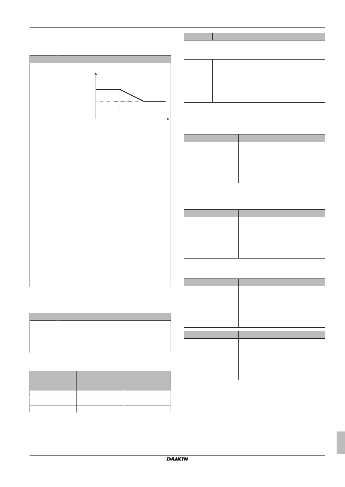
8 Configuration
[0-00]
[0-01]
T
a
T
t
[0-03] [0-02]
Heating WD curve
Set weather-dependent heating for the additional zone (if [3.4] = 1 or
2):
# Code Description
[3.5] [0-00]
Set weather-dependent heating:
[0-01]
[0-02]
[0-03]
# Code Description
Leaving water temperature range for the additional leaving water
temperature zone (= the leaving water temperature zone with the
highest leaving water temperature in heating operation)
[3.8.1] [9-05] Heating minimum: 15°C~37°C
[3.8.2] [9-06] Heating maximum
▪ [2‑0D]=2 (emitter type additional zone
= radiator)
37°C~65°C
▪ Else: 37°C~55°C
Control
The control type is displayed here, but cannot be adjusted. It is
determined by the control type of the main zone. For more info about
▪ Tt: Target leaving water temperature
(additional zone)
▪ Ta: Outdoor temperature
▪ [0-03]: Low outdoor ambient
temperature. –40°C~+5°C
▪ [0-02]: High outdoor ambient
temperature. 10°C~25°C
▪ [0-01]: Desired leaving water
temperature when the outdoor
temperature equals or drops below the
low ambient temperature.
[9‑05]°C~[9‑06]°C
Note: This value should be higher
than [0‑00] as for low outdoor
temperatures warmer water is
required.
▪ [0-00]: Desired leaving water
temperature when the outdoor
temperature equals or rises above the
high ambient temperature.
[9‑05]~min(45, [9‑06])°C
Note: This value should be lower than
[0‑01] as for high outdoor
the functionality, see "8.4.3Main zone"on page53.
# Code Description
[3.9] N/A Control
▪ Leaving water if the control type of the
main zone is Leaving water.
▪ External room thermostat if the control
type of the main zone is External room
thermostat or Room thermostat.
Thermostat type
Only applicable in external room thermostat control. For more info
about the functionality, see "8.4.3Main zone"on page53.
# Code Description
[3.A] [C‑06] External room thermostat type for the
additional zone:
▪ 1: 1 contact. Connected to only 1
digital input (X2M/35a)
▪ 2: 2 contacts. Connected to 2 digital
inputs (X2M/34a and X2M/35a)
Leaving water temperature: Delta T
For more information, see "8.4.3Main zone"on page53.
temperatures less warm water is
required.
Emitter type
For more info about this functionality, see "8.4.3 Main zone" on
page53.
# Code Description
[3.7] [2‑0D] Emitter type
▪ 0: Underfloor heating
▪ 1: Fancoil unit
▪ 2: Radiator
The setting of the emitter type has an influence on the space heating
setpoint range and the target delta T in heating as follows:
Emitter type
Additional zone
Space heating
setpoint range
Target delta T in
heating [1‑0C]
[9‑05]~[9‑06]
0: Underfloor heating Maximum 55°C Variable (see [2.B])
1: Fancoil unit Maximum 55°C Variable (see [2.B])
2: Radiator Maximum 65°C Fixed 10°C
# Code Description
[3.B.1] [1-0C] Delta T heating: A minimum temperature
difference is required for the good
operation of heat emitters in heating
mode.
▪ If [2-0D] = 2, this is fixed to 10°C
▪ Else: 3°C~10°C
# Code Description
[3.B.1] [1-0C] Delta T heating: A minimum temperature
difference is required for the good
operation of heat emitters in heating
mode.
▪ If [2-0D] = 2, this is fixed to 8°C
▪ Else: 3°C~10°C
8.4.5 Space heating
About space operation modes
This unit is a heating only model. The system can heat up a space,
but NOT cool down a space.
Setpoint range
For more information about this setting, also see "8.4.3 Main
zone"on page53.
Operation range
Depending on the average outdoor temperature, the operation of the
unit in space heating is prohibited.
ERGA04~08DAV3(A) + EHVH04+08S23DAV
Daikin Altherma – Low temperature split
4P499573-1A – 2018.11
Installer reference guide
57
Page 58

8 Configuration
a
a
b
a
b c
d
b c
a
b
d
e
f
c
g
b
c
# Code Description
[4.3.1] [4-02] Space heating off temperature: When the
averaged outdoor temperature rises
above this value, space heating is turned
off.
▪ 14°C~35°C
Number of zones
The system can supply leaving water to up to 2 water temperature
zones. During configuration, the number of water zones must be set.
# Code Description
[4.4] [7‑02] ▪ 0: Single zone
Only one leaving water temperature
zone:
CAUTION
If there are 2 zones and the emitter types are wrongly
configured, water of high temperature can be sent towards
a low temperature emitter (underfloor heating). To avoid
this:
▪ Install an aquastat/thermostatic valve to avoid too high
temperatures towards a low temperature emitter.
▪ Make sure you set the emitter types for the main zone
[2.7] and for the additional zone [3.7] correctly in
accordance with the connected emitter.
Pump operation mode
When the space heating operation is OFF, the pump is always OFF.
When space heating operation is ON, you have the choice between
these operation modes:
# Code Description
[4.5] [F–0D] Pump operation mode:
▪ 0 Continuous: Continuous pump
operation, regardless of thermo ON or
OFF condition. Remark: Continuous
pump operation requires more energy
than sample or request pump
operation.
▪ a: Main LWT zone
[4.4] [7‑02] ▪ 1: Dual zone
Two leaving water temperature zones.
The main leaving water temperature
zone consists of the higher load heat
emitters and a mixing station to
achieve the desired leaving water
temperature. In heating:
▪ a: Additional LWT zone: Highest
temperature
▪ b: Main LWT zone: Lowest
temperature
CAUTION
If there are 2 zones, it is important that the zone with the
lowest water temperature is configured as the main zone,
and the zone with the highest water temperature is
configured as the additional zone. Not configuring the
system in this way could cause damage to the heat
emitters.
▪ a: Space heating control
▪ b: Off
▪ c: On
▪ d: Pump operation
[4.5] [F-0D] ▪ 1 Sample: The pump is ON when
there is heating demand as the leaving
water temperature has not yet reached
the desired temperature yet. When
thermo OFF condition occurs, the
pump runs every 3 minutes to check
the water temperature and demand
heating if necessary. Remark: Sample
is ONLY available in leaving water
temperature control.
▪ a: Space heating control
▪ b: Off
▪ c: On
▪ d: LWT temperature
▪ e: Actual
▪ f: Desired
▪ g: Pump operation
Installer reference guide
58
ERGA04~08DAV3(A) + EHVH04+08S23DAV
Daikin Altherma – Low temperature split
4P499573-1A – 2018.11
Page 59

# Code Description
a
d
e
b
b
c
b c
c
[9-0D]=0 [9-0D]=5
a (kPa)
b (l/min)
a (kPa)
b (l/min)
a (kPa)
b (l/min)
a (kPa)
b (l/min)
[9-0D]=6 [9-0D]=7
[9-0D]=8
a (kPa)
b (l/min)
[4.5] [F-0D] ▪ 2 Request: Pump operation based on
request. Example: Using a room
thermostat and thermostat creates
thermo ON/OFF condition. Remark:
NOT available in leaving water
temperature control.
▪ a: Space heating control
▪ b: Off
▪ c: On
▪ d: Heating demand (by external
room thermostat or room
thermostat)
▪ e: Pump operation
Unit type
In this part of the menu it can be read out which type of unit is used:
8 Configuration
# Code Description
[4.6] N/A Unit type:
▪ 1 Cooling only
▪ 2 Heating only
▪ 3 Reversible
Pump limitation
Pump speed limitation [9‑0D] defines the maximum pump speed. In
normal conditions, the default setting should NOT be modified. The
pump speed limitation will be overruled when the flow rate is in the
range of the minimum flow (error 7H).
# Code Description
[4.7] [9-0D] Pump limitation:
▪ 0: No limitation
▪ 1~4: General limitation. There is
limitation in all conditions. The
required delta T control and comfort
are NOT guaranteed.
▪ 5~8: Limitation when no actuators.
When there is no heating output, the
pump speed limitation is applicable.
When there is heating output, the
pump speed is only determined by
delta T in relation to the required
capacity. With this limitation range,
delta T is possible and the comfort is
guaranteed.
a External static pressure
b Water flow rate
Pump outside range
When the pump operation function is disabled the pump will stop if
the outdoor temperature is higher than the value set by the Space
heating off temperature [4‑02]. When the pump operation is enabled,
the pump operation is possible at all outdoor temperatures.
# Code Description
[4.9] [F-00] Pump operation:
▪ 0: Disabled if outdoor temperature is
higher than [4‑02].
▪ 1: Possible at all outdoor
temperatures.
The maximum values depend on the unit type:
ERGA04~08DAV3(A) + EHVH04+08S23DAV
Daikin Altherma – Low temperature split
4P499573-1A – 2018.11
Increase around 0°C
Use this setting to compensate for possible heat losses of the
building due to the evaporation of melted ice or snow. (e.g. in cold
region countries).
In heating operation, the desired leaving water temperature is locally
increased around an outdoor temperature of 0°C.This compensation
can be selected when using an absolute or a weather dependent
desired temperature (see illustration below).
Installer reference guide
59
Page 60

8 Configuration
T
t
T
A
R
L
0°C
T
t
T
A
R
L
0°C
a b
a Absolute desired LWT
b Weather dependent desired LWT
# Code Description
[4.A] [D-03] Increase around 0°C
▪ 0: No
▪ 1: increase 2°C, span 4°C
▪ 2: increase 4°C, span 4°C
▪ 3: increase 2°C, span 8°C
▪ 4: increase 4°C, span 8°C
Overshoot
This function defines how much the water temperature may rise
above the desired leaving water temperature before the compressor
stops. The compressor will start up again when the leaving water
temperature drops below the desired leaving water temperature.
This function is ONLY applicable in heating mode.
# Code Description
[4.B] [9-04] Overshoot
▪ 1°C~4°C
Antifrost
Room frost protection [1.4] prevents the room from getting too cold.
For more information about room frost protection, see
"8.4.2Room"on page52.
INFORMATION
When powerful operation is active, the risk of space
heating and capacity shortage comfort problems is
significant. In case of frequent domestic hot water
operation, frequent and long space heating interruptions
will happen.
Comfort setpoint
Only applicable when domestic hot water preparation is Schedule
only or Schedule + reheat. When programming the schedule, you
can make use of the comfort setpoint as a preset value. When you
later want to change the storage setpoint, you only have to do it in
one place.
The tank will heat up until the storage comfort temperature has
been reached. It is the higher desired temperature when a storage
comfort action is scheduled.
Additionally, a storage stop can be programmed. This feature puts a
stop to tank heating even if the setpoint has NOT been reached.
Only program a storage stop when tank heating is absolutely
undesirable.
# Code Description
[5.2] [6-0A] Comfort setpoint
▪ 30°C~[6‑0E]°C
Eco setpoint
The storage economic temperature denotes the lower desired
tank temperature. It is the desired temperature when a storage
economic action is scheduled (preferably during day).
# Code Description
[5.3] [6-0B] Eco setpoint
▪ 30°C~min(50,[6‑0E])°C
8.4.6 Tank
Tank setpoint screen
You can set the domestic hot water temperature using the setpoint
screen. For more information about how to do this, see
"8.3.5Setpoint screen"on page49.
Powerful operation
You can use powerful operation to immediately start heating up the
water to the preset value (Storage comfort). However, this consumes
extra energy. If powerful operation is active,
the home screen.
To activate powerful operation
Activate or deactivate Powerful operation as follows:
1 Go to [5.1]: Tank > Powerful operation
2 Turn powerful operation Off or On.
Usage example: You immediately need more hot water
If you are in the following situation:
▪ You already consumed most of your hot water.
▪ You cannot wait for the next scheduled action to heat up the DHW
tank.
Then you can activate DHW powerful operation.
Advantage: The DHW tank immediately starts heating up the water
to the preset value (Storage comfort).
will be shown on
Reheat setpoint
Desired reheat tank temperature, used:
▪ in Schedule + reheat mode, during reheat mode: the guaranteed
minimum tank temperature is set by the Reheat setpoint minus the
reheat hysteresis. If the tank temperature drops below this value,
the tank is heated up.
▪ during storage comfort, to prioritize the domestic hot water
preparation. When the tank temperature rises above this value,
domestic hot water preparation and space heating/cooling are
executed sequentially.
# Code Description
[5.4] [6-0C] Reheat setpoint
▪ 30°C~min(50,[6‑0E])°C
Schedule
You can set the tank temperature schedule using the schedule
screen. For more information about this screen, see "8.3.8Schedule
screen: Example"on page50.
Heat up mode
The domestic hot water can be prepared in 3 different ways. They
differ from each other by the way the desired tank temperature is set
and how the unit acts upon it.
Installer reference guide
60
ERGA04~08DAV3(A) + EHVH04+08S23DAV
Daikin Altherma – Low temperature split
4P499573-1A – 2018.11
Page 61

8 Configuration
00.00 22.00 24.0001.00 23.00 t
T
DHW
T
H
T
U
[2-02]
[2-03]
[2-04]
# Code Description
[5.6] [6-0D] Heat up mode
▪ 0: Reheat only: Only reheat operation
is allowed.
▪ 1: Schedule + reheat: The domestic
hot water tank is heated according to a
schedule and between the scheduled
heat up cycles, reheat operation is
allowed.
▪ 2: Schedule only: The domestic hot
water tank can ONLY be heated
according to a schedule.
See the operation manual for more details.
Disinfection
Applies only to installations with a domestic hot water tank.
The disinfection function disinfects the domestic hot water tank by
periodically heating the domestic hot water to a specific temperature.
CAUTION
The disinfection function settings MUST be configured by
the installer according to the applicable legislation.
# Code Description
[5.7.1] [2‑01] Activation
▪ 0: No
▪ 1: Yes
[5.7.2] [2‑00] Operation day
▪ 0: Every day
▪ 1: Monday
▪ 2: Tuesday
▪ 3: Wednesday
▪ 4: Thursday
▪ 5: Friday
▪ 6: Saturday
▪ 7: Sunday
[5.7.3] [2‑02] Start time
[5.7.4] [2‑03] Tank setpoint
70°C
[5.7.5] [2‑04] Duration
5~60minutes
WARNING
Be aware that the domestic hot water temperature at the
hot water tap will be equal to the value selected in field
setting [2-03] after a disinfection operation.
When the high domestic hot water temperature can be a
potential risk for human injuries, a mixing valve (field
supply) shall be installed at the hot water outlet connection
of the domestic hot water tank. This mixing valve shall
secure that the hot water temperature at the hot water tap
never rise above a set maximum value. This maximum
allowable hot water temperature shall be selected
according to the applicable legislation.
CAUTION
Be sure that the disinfection function start time [5.7.3] with
defined duration [5.7.5] is NOT interrupted by possible
domestic hot water demand.
CAUTION
BSH allowance schedule [9.4.2] is used to restrict or allow
anti-legionella heater operation based on a weekly
program. Advice: In order to avoid unsuccessful
disinfection function, at least allow the anti-legionella
heater (by the weekly program) for minimum 4 hours
starting from the scheduled start-up of disinfection. If the
anti-legionella heater is restricted during disinfection, this
function will NOT be successful and the applicable warning
AH will be generated.
INFORMATION
In case of error code AH and no interruption of the
disinfection function occurred due to domestic hot water
tapping, following actions are recommended:
▪ When the Domestic hot water > Type > Reheat or
Reheat + sched. is selected, it is recommended to
program the start-up of the disinfection function at least
4 hours later than the last expected large hot water
tapping. This start-up can be set by installer settings
(disinfection function).
▪ When the Domestic hot water > Type > Scheduled only
is selected, it is recommended to program a Storage
eco 3 hours before the scheduled start-up of the
disinfection function to preheat the tank.
INFORMATION
Disinfection function is restarted in case the domestic hot
water temperature drops 5°C below the disinfection target
temperature within the duration time.
T
Domestic hot water temperature
ERGA04~08DAV3(A) + EHVH04+08S23DAV
Daikin Altherma – Low temperature split
4P499573-1A – 2018.11
DHW
TUUser set point temperature
THHigh set point temperature [2-03]
t Time
INFORMATION
An AH error occurs if you turn off domestic hot water
operation during disinfection.
Maximum DHWtemperature setpoint
The maximum temperature that users can select for the domestic
hot water. You can use this setting to limit the temperatures at the
hot water taps.
INFORMATION
During disinfection of the domestic hot water tank, the
DHWtemperature can exceed this maximum temperature.
INFORMATION
Limit the maximum hot water temperature according to the
applicable legislation.
Installer reference guide
61
Page 62

8 Configuration
T
DHW
T
a
[0-0C]
[0-0B]
[0-0E] [0-0D]
t
T
DHW
T
HP ON
T
HP OFF
T
HP MAX
T
U=TBUH OFF
[6-01]
[6-00]
TU= 60°C
T
HP MAX
= 50°C
[6-01] = 2°C
[6-00] = 2°C
HP
BUH
HP
5
10
20
30
40
46
48
50
60
# Code Description
[5.8] [6-0E] Maximum
The maximum temperature that users
can select for the domestic hot water.
You can use this setting to limit the
temperature at the hot water taps.
The maximum temperature is NOT
applicable during disinfection function.
See disinfection function.
Hysteresis
The following ON hysteresis can be set.
Heat pump ON hysteresis
Applicable when domestic hot water preparation is reheat only.
When the tank temperature drops below the reheat temperature
minus the heat pump ON hysteresis temperature, the tank heats up
to the reheat temperature.
The minimum ON temperature is 20°C, even if setpoint hysteresis is
smaller than 20°C.
# Code Description
[5.9] [6-00] Heat pump ON hysteresis
▪ 2°C~40°C
Reheat hysteresis
Applicable when domestic hot water preparation is scheduled
+reheat. When the tank temperature drops below the reheat
temperature minus the reheat hysteresis temperature, the tank heats
up to the reheat temperature.
# Code Description
[5.A] [6-08] Reheat hysteresis
▪ 2°C~20°C
Setpoint mode
# Code Description
[5.B] N/A Setpoint mode:
▪ Fixed
▪ Weather dependent
# Code Description
[5.C] [0-0E]
Weather-dependent curve
[0-0D]
[0-0C]
[0-0B]
▪ T
: The desired tank temperature.
DHW
▪ Ta: The (averaged) outdoor ambient
temperature
▪ [0-0E]: low outdoor ambient
temperature: -40°C‑5°C
▪ [0-0D]: high outdoor ambient
temperature: 10°C‑25°C
▪ [0-0C]: desired tank temperature when
the outdoor temperature equals or
drops below the low ambient
temperature: 45°C~[6‑0E]°C
▪ [0-0B]: desired tank temperature when
the outdoor temperature equals or
rises above the high ambient
temperature: 35°C~[6‑0E]°C
Margin
In domestic hot water operation, the following hysteresis value can
be set for the heat pump operation:
# Code Description
[5.D] [6-01] The temperature difference determining
the heat pump OFF temperature.
Range: 0°C~10°C
Example: setpoint (TU)>maximum heat pump temperature–[6‑01]
(T
–[6‑01])
HP MAX
WD curve
When weather dependent operation is active the desired tank
temperature is determined automatically depending on the averaged
outdoor temperature: low outdoor temperatures will result in higher
desired tank temperatures as the cold water tap is colder and vice
versa.
In case of Schedule only or Schedule + reheat domestic hot water
preparation, the storage comfort temperature is weather dependent
(according to the weather dependent curve), the storage economic
and reheat temperature are NOT weather dependent.
In case of Reheat only domestic hot water preparation, the desired
tank temperature is weather dependent (according to the weather
dependent curve). During weather dependent operation, the enduser cannot adjust the desired tank temperature on the user
interface. Also see "8.3.7Detailed screen with weather-dependent
curve"on page50.
Installer reference guide
62
BSH Anti‑legionella heater
HP Heat pump. If heating up time by the heat pump takes too
long, auxiliary heating by the anti‑legionella heater can take
T
place
Anti‑legionella heater OFF temperature (TU)
BSH OFF
T
Maximum heat pump temperature at sensor in domestic
HP MAX
hot water tank
T
Heat pump OFF temperature (T
HP OFF
T
Heat pump ON temperature (T
HP ON
T
Domestic hot water temperature
DHW
TUUser set point temperature (as set on the user interface)
t Time
HP MAX
HP OFF
−[6-01])
−[6-00])
Example: setpoint (TU)≤maximum heat pump temperature–[6‑01]
(T
–[6‑01])
HP MAX
ERGA04~08DAV3(A) + EHVH04+08S23DAV
Daikin Altherma – Low temperature split
4P499573-1A – 2018.11
Page 63

t
[6-00]
HP
5
10
20
30
40
43
45
TU=T
HP OFF
T
HP MAX
T
DHW
T
HP ON
50
HP Heat pump. If heating up time by the heat pump takes too
long, auxiliary heating by the anti‑legionella heater can take
place
T
Maximum heat pump temperature at sensor in domestic
HP MAX
hot water tank
T
Heat pump OFF temperature (T
HP OFF
T
Heat pump ON temperature (T
HP ON
T
Domestic hot water temperature
DHW
TUUser set point temperature (as set on the user interface)
t Time
HP MAX
HP OFF
−[6-01])
−[6-00])
INFORMATION
The maximum heat pump temperature depends on the
ambient temperature. For more information, see the
operation range.
8 Configuration
2 Set the first day of your holiday. —
▪ Go to [7.3.2]: From.
▪ Select a date.
▪ Confirm the changes.
3 Set the last day of your holiday. —
▪ Go to [7.3.3]: Till.
▪ Select a date.
▪ Confirm the changes.
Quiet
About quiet mode
You can use quiet mode to decrease the sound of the outdoor unit.
However, this also decreases the heating capacity of the system.
There are multiple quiet mode levels.
You can:
▪ Completely deactivate quiet mode
▪ Manually activate a quiet mode level until the next scheduled
action
▪ Use and program a quiet mode schedule
8.4.7 User settings
Language
# Code Description
[7.1] N/A Language
Time/date
# Code Description
[7.2] N/A Set the local time and date
INFORMATION
By default, daylight savings time is enabled and clock
format is set to 24 hours. If you want to change these
settings, you can do this in the menu structure (User
settings > Time/date) once the unit is initialised.
Holiday
About holiday mode
During your holiday, you can use the holiday mode to deviate from
your normal schedules without having to change them. While holiday
mode is active, space heating operation and domestic hot water
operation will be turned off. Room frost protection and anti-legionella
operation will remain active.
Typical workflow
Using holiday mode typically consists of the following stages:
1 Setting the starting date and ending date of your holiday.
2 Activating the holiday mode.
To check if holiday mode is activated and/or running
If
is activated on the home screen, holiday mode is active.
To configure the holiday
1 Activate the holiday mode. —
▪ Go to [7.3.1]: User settings > Holiday > Activation.
▪ Select On.
INFORMATION
If the outdoor temperature is below zero, we recommend to
NOT use the most quiet level.
To check if quiet mode is active
If
is displayed on the home screen, quiet mode is active.
To use quiet mode
1 Go to [7.4.1]: User settings > Quiet > Activation.
2 Do one of the following: —
If you want to… Then…
Completely deactivate
Select Off.
quiet mode
Manually activate a quiet
mode level
Select the applicable quiet
mode level. Example: Most
quiet.
Use and program a quiet
mode schedule
Select Automatic.
Go to [7.4.2] Schedule and
program the schedule. For
more information about
scheduling, see
"8.3.8Schedule screen:
Example"on page50.
Usage example: Baby is sleeping in the afternoon
If you are in the following situation:
▪ You have programmed a quiet mode schedule:
▪ During the night: Most quiet.
▪ During the day: Off to ensure the heating capacity of the
system.
▪ However, during the afternoon the baby is sleeping and you want
it to be quiet.
Then you can do the following:
1 Go to [7.4.1]: User settings > Quiet > Activation.
2 Select Most quiet.
Advantage:
ERGA04~08DAV3(A) + EHVH04+08S23DAV
Daikin Altherma – Low temperature split
4P499573-1A – 2018.11
Installer reference guide
63
Page 64

8 Configuration
The outdoor unit runs in its most quiet level.
Electricity prices and gas price
Only applicable in combination with the bivalent function. See also
"Bivalent"on page71.
# Code Description
[7.5.1] N/A Electricity price > High
[7.5.2] N/A Electricity price > Medium
[7.5.3] N/A Electricity price > Low
[7.6] N/A Gas price
INFORMATION
Electricity price can only be set when bivalent is ON
([9.C.1] or [C-02]). These values can only be set in menu
structure [7.5.1], [7.5.2] and [7.5.3]. Do NOT use overview
settings.
To set the gas price
1 Go to [7.6]: User settings > Gas price.
2 Select the correct gas price.
3 Confirm the changes.
INFORMATION
Price value ranging from 0.00~990 valuta/kWh (with 2
significant values).
To set the electricity price
1 Go to [7.5.1]/[7.5.2]/[7.5.3]: User settings > Electricity
price > High/Medium/Low.
2 Select the correct electricity price.
3 Confirm the changes.
4 Repeat this for all three electricity prices. —
To set the gas price in case of an incentive per kWh renewable energy
Calculate the value for the gas price with the following formula:
▪ Actual gas price+(Incentive/kWh×0.9)
For the procedure to set the gas price, see "To set the gas price"on
page64.
To set the electricity price in case of an incentive per kWh renewable energy
Calculate the value for the electricity price with following formula:
▪ Actual electricity price+Incentive/kWh
For the procedure to set the electricity price, see "To set the
electricity price"on page64.
Example
This is an example and the prices and/or values used in this
example are NOT accurate.
Data Price/kWh
Gas price 4.08
Electricity price 12.49
Renewable heat incentive per
kWh
Calculation of the gas price:
Gas price=Actual gas price+(Incentive/kWh×0.9)
Gas price=4.08+(5×0.9)
Gas price=8.58
Calculation of the electricity price:
Electricity price=Actual electricity price+Incentive/kWh
Electricity price=12.49+5
Electricity price=17.49
5
INFORMATION
Price value ranging from 0.00~990 valuta/kWh (with 2
significant values).
INFORMATION
If no schedule is set, the Electricity price for High is taken
into account.
To set the electricity price schedule timer
1 Go to [7.5.4]: User settings > Electricity price >
Schedule.
2 Program the selection using the scheduling screen.
You can set the High, Medium and Low electricity
prices according to your electricity supplier.
3 Confirm the changes.
INFORMATION
The values correspond with the electricity price values for
High, Medium and Low previously set. If no schedule is
set, the electricity price for High is taken into account.
About energy prices in case of an incentive per kWh renewable energy
An incentive can be taken into account when setting the energy
prices. Although the running cost can increase, the total operation
cost, taking into account the reimbursement will be optimized.
NOTICE
Make sure to modify the setting of the energy prices at the
end of the incentive period.
—
Price Value in breadcrumb
Gas: 4.08/kWh [7.6]=8.6
Electricity: 12.49/kWh [7.5.1]=17
8.4.8 Information
Dealer information
The installer can fill in his contact number here.
# Code Description
[8.3] N/A Number that users can call in case of
problems.
Possible read-out information
In menu… You can read out…
[8.1] Energy data Produced energy, consumed
electricity, and consumed gas
[8.2] Malfunction history Malfunction history
[8.3] Dealer information Contact/helpdesk number
[8.4] Sensors Room, tank or domestic hot
water, outside, and leaving water
temperature (if applicable)
[8.5] Actuators Status/mode of each actuator
Example: Domestic hot water
pump ON/OFF
[8.6] Operation modes Current operation mode
Example: Defrost/oil return
mode
Installer reference guide
64
ERGA04~08DAV3(A) + EHVH04+08S23DAV
Daikin Altherma – Low temperature split
4P499573-1A – 2018.11
Page 65

8 Configuration
c
f
a
j
b
g
h
i
c
a
d f
e g
h
i
j
b
In menu… You can read out…
[8.7] About Version information about the
system
[8.8] Connection status Information about the connection
status of the unit, the room
thermostat and the LAN adapter.
8.4.9 Installer settings
Configuration wizard
After first power ON of the system, the user interface will guide you
using the configuration wizard. This way you can set the most
important initial settings. This way the unit will be able to run
properly. Afterwards, more detailed settings can be done via the
menu structure if required.
To restart the configuration wizard, go to Installer settings >
Configuration wizard [9.1].
Domestic hot water
Domestic hot water
The following setting determines if the system can prepare domestic
hot water or not, and which tank is used. This setting is read only.
# Code Description
[9.2.1] [E‑05]
[E-05] Can the system prepare domestic hot water?
[E-06] Is a domestic hot water tank installed in the system?
[E-07] What kind of domestic hot water tank is installed?
DHW pump
# Code Description
[9.2.2] [D‑02] DHW pump:
Instant hot water Disinfection
(*)
▪ Integrated
(*)
[E‑06]
(*)
[E‑07]
(*) Menu structure setting [9.2.1] replaces the following 3
overview settings:
The anti-legionella heater will also be
used during disinfection.
▪ 0: No DHW pump: NOT installed
▪ 1: Instant hot water: Installed for
instant hot water when water is
tapped. The user sets the operation
timing of the domestic hot water pump
using the schedule. Control of this
pump is possible with the user
interface.
▪ 2: Disinfection: Installed for
disinfection. It runs when the
disinfection function of the domestic
hot water tank is running. No further
settings are needed.
See also illustrations below.
Domestic hot water pump installed for…
h Domestic hot water OUT
i Recirculation connection
j Anti‑legionella heater
DHW pump schedule
Here you can program a schedule for the DHW pump (only for field
supplied domestic hot water pump for secondary return).
Program a domestic hot water pump schedule to determine when
to turn on and off the pump.
When turned on, the pump runs and makes sure hot water is
instantly available at the tap. To save energy, only turn on the pump
during periods of the day when instant hot water is necessary.
Backup heater
Besides the type of backup heater, the voltage, configuration and
capacity must be set on the user interface.
The capacities for the different steps of the backup heater must be
set for the energy metering and/or power consumption feature to
work properly. When measuring the resistance value of each heater,
you can set the exact heater capacity and this will lead to more
accurate energy data.
Backup heater type
The backup heater is adapted to be connected to most common
European electricity grids. The type of backup heater must be set on
the user interface. For units with a built-in backup heater, the type of
heater can be viewed but not changed.
# Code Description
[9.3.1] [E‑03] ▪ 0: No heater
▪ 1: External heater
Voltage
The optional external BUH can be set to 230V, 1ph, 230V, 3ph or
400V, 3ph.
# Code Description
[9.3.2] [5‑0D] ▪ 0: 230V, 1ph
▪ 1: 230V, 3ph
▪ 2: 400V, 3ph
Configuration
The backup heater can be configured in different ways. It can be
chosen to have a 1-step only backup heater or a backup heater with
2 steps. If 2 steps, the capacity of the second step depends on this
setting. It can also be chosen to have a higher capacity of the
second step in emergency.
# Code Description
[9.3.3] [4‑0A] ▪ 0: Relay 1
▪ 1: Relay 1 / Relay 1+2
▪ 2: Relay 1 / Relay 2
▪ 3: Relay 1 / Relay 2 Emergency Relay
(a)
1+2
(a) Not available for 3V models.
INFORMATION
Settings [9.3.3] and [9.3.5] are linked. Changing one
setting influences the other. If you change one, check if the
other is still as expected.
(a)
(a)
INFORMATION
a Indoor unit
b Tank
c Domestic hot water pump
d Heater element
e Non‑return valve
f Shower
g Cold water
ERGA04~08DAV3(A) + EHVH04+08S23DAV
Daikin Altherma – Low temperature split
4P499573-1A – 2018.11
During normal operation, the capacity of the second step of
the backup heater at nominal voltage is equal to
[6‑03]+[6‑04].
Installer reference guide
65
Page 66

8 Configuration
INFORMATION
If [4‑0A]=3 and emergency mode is active, the power
usage of the backup heater is maximal and equal to
2×[6‑03]+[6‑04].
INFORMATION
Only for systems with integrated domestic hot water tank: If
the storage temperature set point is higher than 50°C,
Daikin recommends NOT to disable the backup heater
second step because it will have a big impact on the
required time for the unit to heat up the domestic hot water
tank.
Capacity step 1
# Code Description
[9.3.4] [6‑03] ▪ The capacity of the first step of the
backup heater at nominal voltage.
Additional capacity step 2
# Code Description
[9.3.5] [6‑04] ▪ The capacity difference between the
second and first step of the backup
heater at nominal voltage. Nominal
value depends on backup heater
configuration.
Equilibrium
# Code Description
[9.3.6] [5-00] Equilibrium: Is backup heater operation
allowed above equilibrium temperature
during space heating operation?
▪ 1: NOT allowed
▪ 0: Allowed
[9.3.7] [5-01] Equilibrium temperature: Outdoor
temperature below which operation of
the backup heater is allowed.
Range: –15°C~35°C
Operation
# Code Description
[9.3.8] [4‑00] Backup heater operation:
▪ 0: Restricted
▪ 1: Allowed
▪ 2: Only DHW Enabled for domestic hot
water, disable for space heating
INFORMATION
Only for systems with integrated domestic hot water tank: If
backup heater operation during space heating needs to be
limited but can be allowed for domestic hot water
operation, then set [4‑00] to 2.
Anti-legionella heater
Capacity
The capacity of the anti-legionella heater must be set for the energy
metering and/or power consumption control feature to work properly.
When measuring the resistance value of the anti-legionella heater,
you can set the exact heater capacity and this will lead to more
accurate energy data.
# Code Description
[9.4.1] [6‑02] Capacity [kW]. Only applies to domestic
hot water tank with an internal antilegionella heater. The capacity of the
anti-legionella heater at nominal voltage.
Range: 0~10kW
BSH allowance schedule
Program when the anti-legionella heater can operate. You can set a
schedule for the anti-legionella heater here using the schedule
screen. Two actions per day are allowed in a week schedule. For
more information, see "8.3.8 Schedule screen: Example" on
page50.
Example: Only allow the anti-legionella heater to operate during the
night.
BSH eco timer
# Code Description
[9.4.3] [8-03] Anti-legionella heater delay timer.
Start-up delay time for the anti-legionella
heater when domestic hot water mode is
active.
▪ When domestic hot water mode is
NOT active, the delay time is
20minutes.
▪ The delay time starts from anti-
legionella heater ON temperature.
▪ By adapting the anti-legionella heater
delay time versus the maximum
running time, you can find an optimal
balance between the energy efficiency
and the heat up time.
▪ If the anti-legionella heater delay time
is set too high, it might take a long
time before the domestic hot water
reaches its set temperature.
▪ The setting [8‑03] is only meaningful if
setting [4‑03]=1. Setting [4‑03]=0/2/3/4
limits the anti-legionella heater
automatically in relation to heatpump
operation time in domestic water
heating mode.
▪ Make sure that [8‑03] is always in
relation with the maximum running
time [8‑01].
Range: 20~95 minutes
Operation
# Code Description
[9.4.4] [4-03] Defines the operation permission of the
anti-legionella heater depending on
ambient, domestic hot water temperature
or operation mode of heat pump. This
setting is only applicable in reheat mode
for applications with separate domestic
hot water tank. When setting
[4‑03]=1/2/3/4, the anti-legionella heater
operation can still be restricted by the
anti-legionella heater allowance
schedule.
Installer reference guide
66
ERGA04~08DAV3(A) + EHVH04+08S23DAV
Daikin Altherma – Low temperature split
4P499573-1A – 2018.11
Page 67

8 Configuration
# Code Description
[9.4.4] [4-03] ▪ 0: Anti-legionella heater operation is
NOT allowed except for "Disinfection
function" and "Powerful domestic
water heating".
Only use this in case the heat pump
capacity can cover the heating
requirements of the house and
domestic hot water during the
complete heating season.
The anti-legionella heater will not be
allowed to operate when Ta<[5‑03] and
[5‑02]=1. The domestic hot water
temperature can be maximum the heat
pump OFF temperature.
[9.4.4] [4-03] ▪ 1: Anti-legionella heater operation is
allowed when required.
[9.4.4] [4-03] ▪ 2: The anti-legionella heater is allowed
outside the operation range of the heat
pump for domestic hot water
operation.
Anti-legionella heater operation is only
allowed if:
▪ Ambient temperature is out of the
operating range: Ta<[5‑03] or
Ta>35°C
The anti-legionella heater is only
allowed to operate when Ta<[5‑03] if
space heating priority is enabled
([5‑02]=1).
▪ Domestic hot water temperature is
2°C lower than the heatpumpOFF
temperature.
If bivalent operation is enabled
([C‑02]=1) and permission signal for
auxiliary boiler is ON, the anti-legionella
heater will be restricted even when
Ta<[5‑03].
9.4.4 [4-03] ▪ 3: The anti-legionella heater is allowed
when the heat pump is NOT active in
domestic hot water operation.
Same as setting 1, but simultaneous
heat pump domestic hot water
operation and anti-legionella heater
operation is not allowed.
9.4.4 [4-03] ▪ 4: Anti-legionella heater operation is
NOT allowed except for "Disinfection
function".
Only use this in case the capacity of
the heat pump can cover the heating
requirements of the house and
domestic hot water over the complete
heating season.
The anti-legionella heater will not be
allowed to operate when Ta<[5‑03] and
[5‑02]=1. The domestic hot water
temperature can be maximum the heat
pump OFF temperature.
Emergency
Emergency
When the heat pump fails to operate, the optional backup heater and
anti-legionella heater can serve as an emergency heater and either
automatically or non-automatically take over the heat load.
▪ When auto emergency is set to Automatic and a heat pump failure
occurs, the optional backup heater will automatically take over the
heat load, and the anti-legionella heater will automatically take
over the domestic hot water production.
▪ When auto emergency is set to Manual and a heat pump failure
occurs, the domestic hot water and space heating operation will
stop and need to be recovered manually via the user interface. To
recover operation manually, go to the Malfunctioning main menu
screen, where the user interface will then ask you to confirm
whether the optional backup heater or anti-legionella heater can
take over the heat load or not.
We recommend to set Emergency to Automatic if the house is
unattended for longer periods.
# Code Description
[9.5] N/A ▪ 0: Manual
▪ 1: Automatic
INFORMATION
The auto emergency setting can be set in the menu
structure of the user interface only.
INFORMATION
If [4‑03]=1 or 3, then Emergency=Manual is not applicable
for the anti-legionella heater.
INFORMATION
If a heat pump failure occurs and Emergency is set to
Manual, the room frost protection function, the underfloor
heating screed dryout function, and the water pipe
antifreeze function will remain active even if the user does
NOT confirm emergency operation.
Balancing
Priorities
For systems with an integrated domestic hot water tank
# Code Description
[9.6.1] [5‑02] Space heating priority: Defines whether
backup heater (if applicable) will assist
the heat pump during domestic hot
water operation.
Enable this function to shorten tank
heating operation time and interruption
of the space heating cycle.
This setting MUST always be 1.
[5‑01] Equilibrium temperature and
[5‑03] Space heating priority
temperature are related to backup
heater (if applicable). So, you must set
[5‑03] equal or a few degrees higher
than [5‑01].
If the backup heater operation is limited
([4‑00]=0) and the outdoor temperature
is lower than setting [5‑03], the
domestic hot water will not be heated
with the optional backup heater.
[9.6.2] [5‑03] Priority temperature: Defines the
outdoor temperature which below the
domestic hot water will be heated by
anti-legionella heater only.
Range: –15°C~35°C
ERGA04~08DAV3(A) + EHVH04+08S23DAV
Daikin Altherma – Low temperature split
4P499573-1A – 2018.11
Installer reference guide
67
Page 68

8 Configuration
t
1
0
1
0
[8-01] [8-02]
t
T
A
0
[8-01]
[5-03] [4-02]
[8-02]
[8-01]+
[8-04]
# Code Description
[9.6.3] [5-04] Offset BSH setpoint: Set point
correction for domestic hot water
temperature: set point correction for the
desired domestic hot water
temperature, to be applied at low
outdoor temperature when space
heating priority is enabled. The
corrected (higher) set point will make
sure that the total heat capacity of the
water in the tank remains
approximately unchanged, by
compensating for the colder bottom
water layer of the tank (because the
heat exchanger coil is not operational)
with a warmer top layer.
Range: 0°C~20°C
Timers for simultaneous space and domestic hot water
operation request
# Code Description
[9.6.4] [8-02] Anti-recycle timer: Minimum time
between two cycles for domestic hot
water. The actual anti-recycling time also
depends on setting [8-04].
Range: 0~10 hours
Remark: The minimum time is 0.5 hours
even when the selected value is 0.
[9.6.5] N/A Minimum running timer:
Do NOT change.
[9.6.6] [8-01] Maximum running timer for domestic hot
water operation. Domestic hot water
heating stops even when the target
domestic hot water temperature is NOT
reached. The actual maximum running
time also depends on setting [8-04].
▪ When Control=Room thermostat: This
preset value is only taken into account
if there is a request for space heating.
If there is NO request for space
heating, the tank is heated until the
setpoint has been reached.
▪ When Control≠Room thermostat: This
preset value is always taken into
account.
Range: 5~95 minutes
[9.6.7] [8-04] Additional timer: Additional running time
for the maximum running time depending
on the outdoor temperature [4-02].
Range: 0~95 minutes
[8-04]: Additional timer at [4-02]
TAAmbient (outdoor) temperature
t Time
Anti-recycle timer
Maximum running time domestic hot water
Water pipe freeze prevention
Only relevant for installations with water piping outdoors. This
function tries to protect outdoor water piping from freezing.
# Code Description
[9.7] [4-04] Water pipe freeze prevention:
▪ 0: Intermittent
▪ 1: Continuous
▪ 2: Off
NOTICE
If the system does NOT contain a backup heater, then:
▪ Make sure that the room antifrost control is activated
([2-06]=1).
▪ Do NOT change the default room antifrost temperature
[2-05].
▪ Make sure that the water pipe freeze prevention is
activated ([4-04]≠2).
Benefit kWh power supply
INFORMATION
The preferential kWh rate power supply contact is
connected to the same terminals (X5M/9+10) as the safety
thermostat. It is only possible for the system to have
EITHER preferential kWh rate power supply OR a safety
thermostat.
[8-02]: Anti-recycle timer
Installer reference guide
1 Heat pump domestic water heating mode (1=active, 0=not
2 Hot water request for heat pump (1=request, 0=no request)
t Time
68
active)
ERGA04~08DAV3(A) + EHVH04+08S23DAV
Daikin Altherma – Low temperature split
4P499573-1A – 2018.11
Page 69

8 Configuration
# Code Description
[9.8.1] [D-01] Connection to a Benefit kWh power
supply or a Safety thermostat
▪ 0 No: The outdoor unit is connected to
a normal power supply.
▪ 1 Open: The outdoor unit is connected
to a preferential kWh rate power
supply. When the preferential kWh
rate signal is sent by the electricity
company, the contact will open and
the unit will go in forced off mode.
When the signal is released again, the
voltage-free contact will close and the
unit will restart operation. Therefore,
always enable the auto restart
function.
▪ 2 Closed: The outdoor unit is
connected to a preferential kWh rate
power supply. When the preferential
kWh rate signal is sent by the
electricity company, the contact will
close and the unit will go in forced off
mode. When the signal is released
again, the voltage-free contact will
open and the unit will restart
operation. Therefore, always enable
the auto restart function.
▪ 3 Safety thermostat: A safety
thermostat is connected to the system
(normal closed contact)
[9.8.2] [D-00] Allow heater: Which heaters are allowed
to operate during preferential kWh rate
power supply?
▪ 0 No: None
▪ 1 Only BSH: Anti-legionella heater
only
▪ 2 Only BUH: Backup heater only (if
applicable)
▪ 3 All: All heaters
See table below.
Setting2 is only meaningful if the
preferential kWh rate power supply is of
type1 or indoor unit is connected to a
normal kWh rate power supply (via
X2M/5‑6) and the optional backup heater
is NOT connected to the preferential
kWh rate power supply.
[9.8.3] [D-05] Allow pump:
▪ 0 No: Pump is forced off
▪ 1 Yes: No limitation
# Code Description
[9.9.1] [4-08] Power consumption control:
▪ 0 No: Disabled.
▪ 1 Continuous: Enabled: You can set
one power limitation value (in A or
kW) to which the system power
consumption will be limited for all the
time.
▪ 2 Inputs: Enabled: You can set up to
four different power limitation values
(in A or kW) to which the system
power consumption will be limited
when the corresponding digital input
asks.
[9.9.2] [4-09] Type:
▪ 0 Amp: The limitation values are set
in A.
▪ 1 kW: The limitation values are set in
kW.
Limit when [9.9.1]=Continuous and [9.9.2]=Amp:
# Code Description
[9.9.3] [5-05] Limit: Only applicable in case of full
time current limitation mode.
0A~50A
Limits when [9.9.1]=Inputs and [9.9.2]=Amp:
# Code Description
[9.9.4] [5-05] Limit 1: 0A~50A
[9.9.5] [5-06] Limit 2: 0A~50A
[9.9.6] [5-07] Limit 3: 0A~50A
[9.9.7] [5-08] Limit 4: 0A~50A
Limit when [9.9.1]=Continuous and [9.9.2]=kW:
# Code Description
[9.9.8] [5-09] Limit: Only applicable in case of full
time power limitation mode.
0kW~20kW
Limits when [9.9.1]=Inputs and [9.9.2]=kW:
# Code Description
[9.9.9] [5-09] Limit 1: 0kW~20kW
[9.9.A] [5-0A] Limit 2: 0kW~20kW
[9.9.B] [5-0B] Limit 3: 0kW~20kW
[9.9.C] [5-0C] Limit 4: 0kW~20kW
[D‑00] Anti-legionella
heater
0 Forced OFF Forced OFF Forced OFF
1 Permitted
2 Forced OFF Permitted
3 Permitted
Backup heater
(if applicable)
Compressor
Power consumption control
Power consumption control
See "5 Application guidelines" on page10 for detailed information
about this functionality.
ERGA04~08DAV3(A) + EHVH04+08S23DAV
Daikin Altherma – Low temperature split
4P499573-1A – 2018.11
Installer reference guide
69
Page 70

8 Configuration
Priority heater
# Code Description
[9.9.D] [4-01] Power consumption control
DISABLED [4‑08]=0
▪ 0 None : Backup heater and booster
heater can operate simultaneously.
▪ 1 Booster heater: The booster heater
is prioritized.
▪ 2 Backup heater: The backup heater
is prioritized.
Power consumption control
ENABLED [4‑08]=1/2
▪ 0 None : Depending on the power
limitation level, the booster heater
will be limited first, before the backup
heater is limited.
▪ 1 Booster heater: Depending on the
power limitation level, the backup
heater will be limited first, before the
booster heater is limited.
▪ 2 Backup heater: Depending on the
power limitation level, the booster
heater will be limited first, before the
backup heater is limited.
Note: In case power consumption control is DISABLED (for all
models) the setting [4‑01] defines whether backup heater and
booster heater can operate simultaneously, or if the booster heater/
backup heater has priority over the backup heater/booster heater.
In case power consumption control is ENABLED, the setting [4‑01]
defines the priority of the electrical heaters depending on applicable
limitation.
INFORMATION
Anti-legionella heater. In the menu structure the term
"Booster heater" is used. However, this is actually an antilegionella heater.
Energy metering
Energy metering
If energy metering is performed by the use of external power meters,
configure the settings as described below. Select the pulse
frequency output of each power meter in accordance with the power
meter specifications. It is possible to connect up to 2 power meters
with different pulse frequencies. If only 1 or no power meter is used,
select 'None' to indicate the corresponding pulse input is NOT used.
# Code Description
[9.A.1] [D‑08] Electricity meter 1:
▪ 0 None: NOT installed
▪ 1 1/10kWh: Installed
▪ 2 1/kWh: Installed
▪ 3 10/kWh: Installed
▪ 4 100/kWh: Installed
▪ 5 1000/kWh: Installed
# Code Description
[9.A.2] [D‑09] Electricity meter 2:
▪ 0 None: NOT installed
▪ 1 1/10kWh: Installed
▪ 2 1/kWh: Installed
▪ 3 10/kWh: Installed
▪ 4 100/kWh: Installed
▪ 5 1000/kWh: Installed
Sensors
External sensor
# Code Description
[9.B.1] [C–08] External sensor : When an optional
external ambient sensor is connected,
the type of the sensor must be set.
▪ 0 None : NOT installed. The thermistor
in the user interface and in the outdoor
unit are used for measurement.
▪ 1 Outdoor: Connected to PCB of the
indoor unit measuring the outdoor
temperature. Remark: For some
functionality, the temperature sensor
in the outdoor unit is still used.
▪ 2 Room: Connected to PCB of the
indoor unit measuring the indoor
temperature. The temperature sensor
in the user interface is NOT used
anymore. Remark: This value has
only meaning in room thermostat
control.
Ext. amb. sensor offset
ONLY applicable in case an external outdoor ambient sensor is
connected and configured.
You can calibrate the external outdoor ambient temperature sensor.
It is possible to give an offset to the thermistor value. This setting
can be used to compensate for situations where the external outdoor
ambient sensor cannot be installed on the ideal installation location.
# Code Description
[9.B.2] [2-0B] Ext. amb. sensor offset: Offset on the
ambient temperature measured on the
external outdoor temperature sensor.
▪ –5°C~5°C, step 0.5°C
Averaging time
The average timer corrects the influence of ambient temperature
variations. The weather-dependent set point calculation is done on
the average outdoor temperature.
The outdoor temperature is averaged over the selected time period.
# Code Description
[9.B.3] [1-0A] Averaging time:
▪ 0: No averaging
▪ 1: 12hours
▪ 2: 24hours
▪ 3: 48hours
▪ 4: 72hours
Installer reference guide
70
ERGA04~08DAV3(A) + EHVH04+08S23DAV
Daikin Altherma – Low temperature split
4P499573-1A – 2018.11
Page 71

8 Configuration
YC Y1 Y2 Y3 Y4
X1 X2 X3 X4
OFF ON
X2M
SS1
X1M
T
A
[C-03]
[C-04]
a
b
T
A
T
calc
[C-03]+[C-04]
3°C
[C-03]
a
b
Bivalent
Bivalent
Only applies to indoor unit installations with an auxiliary boiler
(alternating operation, connected in parallel). The purpose of
bivalent operation is to determine which heating source can/will
provide the space heating, either the indoor unit or an auxiliary
boiler.
# Code Description
[9.C.1] [C-02] Bivalent: Indicates if the space heating is
also performed by means of another heat
source than the system.
▪ 0 No: Not installed
▪ 1 Yes: Installed. The auxiliary boiler
(gas boiler, oil burner) will operate
when the outdoor ambient temperature
is low. During bivalent operation, the
heat pump is turned off. Set this value
in case an auxiliary boiler is used.
▪ If Bivalent is enabled: When the outdoor temperature drops below
the bivalent ON temperature (fixed or variable based on energy
prices), the space heating by the indoor unit stops automatically
and the permission signal for the auxiliary boiler is active.
▪ If Bivalent is disabled: Space heating is only done by the indoor
unit within the operation range. The permission signal for the
auxiliary boiler is always inactive.
INFORMATION
▪ The combination of setting [4‑03]=0/2 with bivalent
operation at low outdoor temperature can result in
domestic hot water shortage.
▪ The bivalent operation function has no impact on the
domestic water heating mode. The domestic hot water
is still and only heated by the indoor unit.
▪ The permission signal for the auxiliary boiler is located
on the EKRP1HB (digital I/O PCB). When it is
activated, the contact X1, X2 is closed and open when
it is deactivated. See illustration below for the
schematic location of this contact.
Set all electricity prices ([7.5.1]~[7.5.3]) to "0" in the menu structure.
Also set the following values:
NOTICE
Do NOT use overview settings!
# Code Description
[9.C.3] [C-03] Bivalent ON temperature: Defines the
outdoor temperature below which the
permission signal for the auxiliary boiler
is active (X1 and X2 on EKRP1HB is
closed) and space heating by indoor unit
is stopped.
[9.C.4] [C-04] Hysteresis: Defines the temperature
difference between the ON temperature
and the OFF temperature.
Permission signal X1–X2
TAOutdoor temperature
[C-03] Bivalent ON temperature (fixed)
a Auxiliary boiler active
b Auxiliary boiler inactive
Possibility 2: Based on the outdoor temperature and energy prices
The installer can set a temperature range [C‑04]. Depending on the
energy prices, a calculated point T
varies within a range between
calc
[C‑03] and [C‑03]+[C‑04]. It is recommended to choose [C‑04] bigger
than the default value to have an optimal operation when choosing
possibility 2.
Electricity and gas prices
# Code Description
[7.5.1] N/A Electricity price > High
[7.5.2] N/A Electricity price > Medium
[7.5.3] N/A Electricity price > Low
[7.6] N/A Gas price
INFORMATION
Electricity price can only be set when bivalent is ON
([9.C.1] or [C-02]). These values can only be set in menu
structure [7.5.1], [7.5.2] and [7.5.3]. Do NOT use overview
settings.
When the outdoor temperature reaches below the T
point, then
calc
the permission signal for the auxiliary boiler becomes active. To
prevent too much switching, there is a hysteresis of 3°C.
Boiler efficiency
Depending on the used boiler, this should be chosen as follows:
# Code Description
[9.C.2] [7‑05] ▪ 0: Very high
▪ 1: High
▪ 2: Medium
▪ 3: Low
▪ 4: Very low
Possibility 1: Based on the outdoor temperature
ERGA04~08DAV3(A) + EHVH04+08S23DAV
Daikin Altherma – Low temperature split
4P499573-1A – 2018.11
# Code Description
[9.C.3] [C-03] Bivalent ON temperature: Below this
temperature bivalent operation will
always be ON.
[9.C.4] [C-04] Operation range between which T
calculated.
Permission signal X1–X2 (EKRP1HB)
TAOutdoor temperature
T
Bivalent ON temperature (variable). Below this
calc
temperature, the auxiliary boiler will always be ON. T
never go below [C‑03] or above [C‑03]+[C‑04].
a Auxiliary boiler active
Installer reference guide
calc
is
can
calc
71
Page 72

8 Configuration
b Auxiliary boiler inactive
CAUTION
Make sure to observe all rules mentioned in application
guideline 5 when bivalent operation function is enabled.
Daikin shall NOT be held liable for any damage resulting
from failure to observe this rule.
Alarm output
Alarm output
# Code Description
[9.D] [C–09] Alarm output: Indicates the logic of the
alarm output on the digital I/O PCB
during malfunctioning.
▪ 0 Abnormal: The alarm output will be
powered when an alarm occurs. By
setting this value, a distinction is made
between the detection of an alarm,
and the detection of a power failure.
▪ 1 Normal : The alarm output will NOT
be powered when an alarm occurs.
See also table below (Alarm output
logic).
Alarm output logic
[C-09] Alarm No alarm No power
supply to unit
0 Closed output Open output Open output
1 Open output Closed output
Auto restart
Auto restart
When power returns after a power supply failure, the auto restart
function reapplies the remote controller settings at the time of the
power failure. Therefore, it is recommended to always enable the
function.
If the preferential kWh rate power supply is of the type that power
supply is interrupted, always enable the auto restart function.
Continuous indoor unit control can be guaranteed independent of the
preferential kWh rate power supply status, by connecting the indoor
unit to a normal kWh rate power supply.
Disable protections
INFORMATION
The software is equipped with an "installer-on-site" mode
([9.G]: Disable protections), that disables automatic
operation by the unit. At first installation, setting Disable
protections is by default set to Yes, meaning automatic
operation is disabled. All protective functions are then
disabled. If the user interface home pages are off, the unit
will NOT operate automatically. To enable automatic
operation and the protective functions, set Disable
protections to No.
36 hours after the first power-on, the unit will automatically
set Disable protections to No, ending "installer-on-site"
mode and enabling the protective functions. If – after first
installation – the installer returns to the site, the installer
has to set Disable protections to Yes manually.
# Code Description
[9.G] N/A Disable protections
▪ 0: No
▪ 1: Yes
Forced defrost
Forced defrost
Manually start a defrost operation.
# Code Description
[9.H] N/A Do you want to start a defrost operation?
▪ Back
▪ OK
Overview field settings
All settings can be done using the menu structure. If for any reason it
is required to change a setting using the overview settings, then the
overview settings can be accessed in the field settings overview [9.I].
See "To modify an overview setting"on page47.
# Code Description
[9.E] [C-09] Auto restart:
▪ 0: Manual
▪ 1: Automatic
Power saving function
Power saving function
Defines whether the outdoor unit power supply can be interrupted
(internally by indoor unit control) during stand-still conditions (no
space heating/cooling nor domestic hot water demand). The final
decision to allow power interruption of the outdoor unit during
standstill depends on the ambient temperature, compressor
conditions and minimum internal timers.
To enable the power saving function setting, [E‑08] needs to be
enabled on the user interface.
# Code Description
[9.F] [E‑08] Power saving function for outdoor unit:
▪ 0: No
▪ 1: Yes
Installer reference guide
72
ERGA04~08DAV3(A) + EHVH04+08S23DAV
Daikin Altherma – Low temperature split
4P499573-1A – 2018.11
Page 73
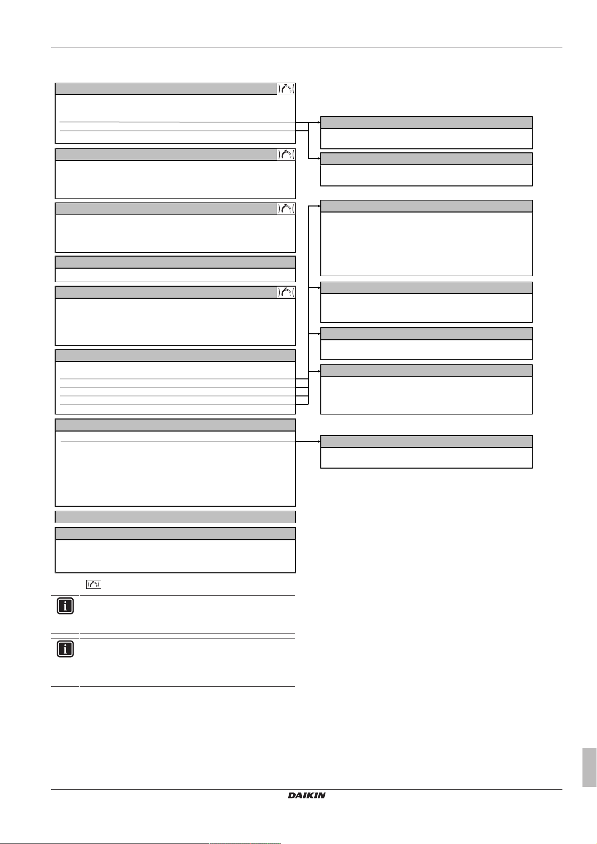
8.5 Menu structure: Overview user settings
[2]
Main zone
Schedule
Heating schedule
Setpoint mode
Heating WD curve
[3]
Additional zone
Schedule
Heating schedule
Setpoint mode
Heating WD curve
[5]
Tank
Powerful operation
Comfort setpoint
Eco setpoint
Reheat setpoint
Schedule
[8.1]
Energy data
Electricity input
Produced heat
[7]
User settings
Language
Time/date
Holiday
Quiet
Electricity price
Gas price
[C]
Operation
Room
Space heating/cooling
Tank
[B]
User profile
[7.3]
Holiday
Activation
From
Till
[7.4]
Quiet
Activation
Schedule
[7.5]
Electricity price
High
Medium
Low
Schedule
[7.2]
Time/date
Hours
Minutes
Year
Month
Day
Daylight savings time
Format
[1.4]
Antifrost
Activation
Room setpoint
[1.5]
Setpoint range
Heating minimum
Heating maximum
[1]
Room
Schedule
Heating schedule
Antifrost
Setpoint range
Room sensor offset
[4]
Space heating/cooling
Operation mode
[8]
Information
Energy data
Malfunction history
Dealer information
Sensors
Actuators
Operation modes
About
Connection status
8 Configuration
Setpoint screen
INFORMATION
Depending on the selected installer settings and unit type,
settings will be visible/invisible.
INFORMATION
Anti-legionella heater. In the menu structure the term
"Booster heater" is used. However, this is actually an antilegionella heater.
ERGA04~08DAV3(A) + EHVH04+08S23DAV
Daikin Altherma – Low temperature split
4P499573-1A – 2018.11
Installer reference guide
73
Page 74

8 Configuration
[9.C]
Bivalent
Bivalent
Boiler efficiency
Temperature
Hysteresis
[9.B]
Sensors
External sensor
Ext. amb. sensor offset
Averaging time
[9.6] Balancing
Space heating priority
Priority temperature
Offset BSH setpoint
Minimum running timer
Anti-recycle timer
Maximum running timer
Additional timer
[9.3]
Backup heater
Backup heater type
Voltage
Configuration
Additional capacity step 2
Capacity step 1
Equilibrium
Equilibrium temperature
Operation
[9.8] Benefit kWh power supply
Benefit kWh power supply
Allow heater
Allow pump
[9.4]
Booster heater
Capacity
BSH allowance schedule
BSH eco timer
Operation
[9.2]
Domestic hot water
Domestic hot water
DHW pump
DHW pump schedule
Solar
[9.9] Power consumption control
Power consumption control
Type
Limit
Limit 1
Limit 2
Limit 3
Limit 4
Priority heater
Electricity meter 2
Electricity meter 1
[9.A] Energy metering
[9]Installer settings
Configuration wizard
Domestic hot water
Backup heater
Booster heater
Emergency
Balancing
Water pipe freeze prevention
Benefit kWh power supply
Power consumption control
Energy metering
Sensors
Bivalent
Alarm output
Auto restart
Power saving function
Disable protections
Overview field settings
Forced defrost
8.6 Menu structure: Overview installer settings
INFORMATION
Solar kit settings are shown but are NOT applicable for this
unit. Settings shall NOT be used or changed.
INFORMATION
Depending on the selected installer settings and unit type,
settings will be visible/invisible.
INFORMATION
Anti-legionella heater. In the menu structure the term
"Booster heater" is used. However, this is actually an antilegionella heater.
Installer reference guide
74
ERGA04~08DAV3(A) + EHVH04+08S23DAV
Daikin Altherma – Low temperature split
4P499573-1A – 2018.11
Page 75

9 Commissioning
9 Commissioning
INFORMATION
The software is equipped with an "installer-on-site" mode
([9.G]: Disable protections), that disables automatic
operation by the unit. At first installation, setting Disable
protections is by default set to Yes, meaning automatic
operation is disabled. All protective functions are then
disabled. If the user interface home pages are off, the unit
will NOT operate automatically. To enable automatic
operation and the protective functions, set Disable
protections to No.
36 hours after the first power-on, the unit will automatically
set Disable protections to No, ending "installer-on-site"
mode and enabling the protective functions. If – after first
installation – the installer returns to the site, the installer
has to set Disable protections to Yes manually.
9.1 Overview: Commissioning
This chapter describes what you have to do and know to
commission the system after it is configured.
Typical workflow
Commissioning typically consists of the following stages:
1 Checking the "Checklist before commissioning".
2 Performing an air purge.
3 Performing a test run for the system.
4 If necessary, performing a test run for one or more actuators.
5 If necessary, performing an underfloor heating screed dryout.
9.2 Precautions when commissioning
INFORMATION
During the first running period of the unit, the required
power may be higher than stated on the nameplate of the
unit. This phenomenon is caused by the compressor, that
needs a continuous run time of 50 hours before reaching
smooth operation and stable power consumption.
NOTICE
NEVER operate the unit without thermistors and/or
pressure sensors/switches. Burning of the compressor
might result.
NOTICE
Do NOT operate the unit until the refrigerant piping is
complete (when operated this way, the compressor will
break).
The following field wiring has been carried out according
to this document and the applicable legislation:
▪ Between the local supply panel and the outdoor unit
▪ Between indoor unit and outdoor unit
▪ Between the local supply panel and the indoor unit
▪ Between the indoor unit and the valves (if applicable)
▪ Between the indoor unit and the room thermostat (if
applicable)
The system is properly earthed and the earth terminals
are tightened.
The fuses or locally installed protection devices are
installed according to this document, and have NOT been
bypassed.
The power supply voltage matches the voltage on the
identification label of the unit.
There are NO loose connections or damaged electrical
components in the switchbox.
There are NO damaged components or squeezed
pipes on the inside of the indoor and outdoor units.
Only if you use the optional backup heater:
Depending on the backup heater type, backup heater
circuit breaker F1B (on the switch box of the backup
heater) is turned ON.
The anti-legionella heater circuit breaker F2B (field
supply) is turned ON.
There are NO refrigerant leaks.
The refrigerant pipes (gas and liquid) are thermally
insulated.
The correct pipe size is installed and the pipes are
properly insulated.
There is NO water leak inside the indoor unit.
The shut-off valves are properly installed and fully open.
The stop valves (gas and liquid) on the outdoor unit are
fully open.
The air purge valve is open (at least 2 turns).
The pressure relief valve purges water when opened.
The minimum water volume is guaranteed in all
conditions. See "To check the water volume" in
"6.4Preparing water piping"on page25.
The domestic hot water tank is filled completely.
9.3 Checklist before commissioning
After the installation of the unit, first check the following items. Once
all below checks are fulfilled, the unit MUST be closed, ONLY then
can the unit be powered up.
You read the complete installation instructions, as
described in the installer reference guide.
The indoor unit is properly mounted.
Only if you use the optional backup heater:
The backup heater is properly mounted.
The outdoor unit is properly mounted.
ERGA04~08DAV3(A) + EHVH04+08S23DAV
Daikin Altherma – Low temperature split
4P499573-1A – 2018.11
9.4 Checklist during commissioning
To perform an air purge.
To perform a test run.
To perform an actuator test run.
Underfloor screed dryout function
The underfloor screed dryout function is started (if
necessary).
Installer reference guide
75
Page 76

9 Commissioning
9.4.1 To check the minimum flow rate
1 Confirm according to the hydraulic configuration
which space heating loops can be closed due to
mechanical, electronic, or other valves.
2 Close all space heating loops that can be closed
(see previous step).
3 Start the pump test run operation (see "9.4.4To
perform an actuator test run"on page77).
4 During pump test run operation, go to Sensors.
5 Select the flow rate information. During test run
operation, the unit can operate below the minimum
required flow rate.
6 Modify the bypass valve setting to reach the
minimum required flow rate + 2l/min.
Minimum required flow rate
12l/min
—
—
—
—
9.4.2 Air purge function
When commissioning and installing the unit, it is very important to
remove all air in the water circuit. When the air purge function is
running, the pump operates without actual operation of the unit and
the removal of air in the water circuit will start.
NOTICE
Before starting the air purge, open the safety valve and
check if the circuit is sufficiently filled with water. Only if
water escapes the valve after opening it, you can start the
air purge procedure.
There are 2 modes for purging air:
▪ Manual: the unit operates with a fixed pump speed and in a fixed
or custom position of the 3-way valve. The custom position of the
3-way valve is a more than helpful feature to remove all air from
the water circuit in the space heating or the domestic hot water
heating mode. Air purge must be performed for both the space
heating and the domestic hot water circuit. The operation speed of
the pump (slow or quick) can also be set.
▪ Automatic: the unit automatically changes the pump speed and
switches the position of the 3-way valve between the space
heating and the domestic hot water heating mode.
Typical workflow
Purging the air from the system should consist of:
1 Performing a manual air purge
2 Performing an automatic air purge
INFORMATION
Start by performing a manual air purge. When almost all
the air is removed, perform an automatic air purge. If
necessary, repeat performing the automatic air purge until
you are sure that all air is removed from the system.
During air purge function, pump speed limitation [9‑0D] is
NOT applicable.
The air purge function automatically stops after 30minutes.
To perform a manual air purge
Conditions: Make sure all operation is disabled. Go to the
Operation menu and turn off Room, Space heating/cooling and Tank
operation.
1 Set the user permission level to Installer. See "To
change the user permission level"on page47.
2 Go to [A.3]: Commissioning > Air purge.
3 In the menu, set Type = Manual.
—
4 Select Start air purge.
5 Select OK to confirm.
Result: The air purge starts. It will stop automatically
when air purge cycle is finished.
6 During manual operation, you can change the
desired pump speed. The position of the 3-way valve
must be changed between space heating and
domestic hot water. To change the settings during
the air purge, open the menu and go to Settings.
▪ Scroll to Circuit and set it to Space/Tank.
▪ Scroll to Pump speed and set it to Low/High.
7 To stop the air purge manually: —
1 Go to Stop air purge.
2 Select OK to confirm.
To perform an automatic air purge
Conditions: Make sure all operation is disabled. Go to the
Operation menu and turn off Room, Space heating/cooling and Tank
operation.
1 Set the user permission level to Installer. See "To
change the user permission level"on page47.
2 Go to [A.3]: Commissioning > Air purge.
3 In the menu, set Type = Automatic.
4 Select Start air purge.
5 Select OK to confirm.
Result: The air purge starts. It stops automatically
when done.
6 To stop the air purge manually: —
1 Go to Stop air purge.
2 Select OK to confirm.
—
9.4.3 To perform an operation test run
Conditions: Make sure all operation is disabled. Go to the
Operation menu and turn off Room, Space heating/cooling and Tank
operation.
1 Set the user permission level to Installer. See "To
change the user permission level"on page47.
2 Go to [A.1]: Commissioning > Operation test run.
3 Select a test from the list. Example: Heating.
4 Select OK to confirm.
Result: The test run starts. It stops automatically
when done (±30min).
To stop the test run manually: —
1 Go to Stop test run.
2 Select OK to confirm.
INFORMATION
When starting up the system in a cold climate, and NO
backup heater kit was installed, it may be required to start
up with a small water volume. To do this, gradually open
the heat emitters. As a result, the water temperature will
gradually rise. Monitor the inlet water temperature ([6.1.6]
in the menu structure) and make sure it does NOT drop
below 15°C.
—
Installer reference guide
76
ERGA04~08DAV3(A) + EHVH04+08S23DAV
Daikin Altherma – Low temperature split
4P499573-1A – 2018.11
Page 77

9 Commissioning
t
T
A1
25°C (1)
35°C (2)
24h (1) 36h (2)
If the installation of the unit has been done correctly, the unit will
start up during test operation in the selected operation mode. During
test mode, the correct operation of the unit can be checked by
monitoring its leaving water temperature (heating/cooling mode) and
tank temperature (domestic hot water mode).
To monitor the temperature:
1 Go to Sensors.
2 Select the temperature information.
9.4.4 To perform an actuator test run
Conditions: Make sure all operation is disabled. Go to the
Operation menu and turn off Room, Space heating/cooling and Tank
operation.
Purpose of the actuator test run is to confirm the operation of the
different actuators (e.g., when you select Pump, a test run of the
pump will start).
1 Set the user permission level to Installer. See "To
change the user permission level"on page47.
2 Go to [A.2]: Commissioning > Actuator test run.
3 Select a test from the list. Example: Pump.
4 Select OK to confirm.
Result: The actuator test run starts. It stops
automatically when done (±30min).
To stop the test run manually: —
1 Go to Stop test run.
2 Select OK to confirm.
—
Possible actuator test runs
▪ Booster heater test
▪ Backup heater 1 test (if applicable)
▪ Backup heater 2 test (if applicable)
▪ Pump test
INFORMATION
Make sure that all air is purged before executing the test
run. Also avoid disturbances in the water circuit during the
test run.
▪ Shut off valve test
▪ Diverter valve test
▪ Bivalent signal test
▪ Alarm output test
▪ C/H signal test
▪ DHW pump test
INFORMATION
▪ If Emergency is set to Manual ([A.6.C]=0), and the unit
is triggered to start emergency operation, the user
interface will ask confirmation before starting. The
underfloor heating screed dryout function is active even
if the user does NOT confirm emergency operation.
▪ During underfloor heating screed dryout, pump speed
limitation [9‑0D] is NOT applicable.
NOTICE
The installer is responsible for:
▪ contacting the screed manufacturer for the initial
heating instructions to avoid cracking the screed,
▪ programming the underfloor heating screed dryout
schedule according to the above instruction of the
screed manufacturer,
▪ checking the proper functioning of the setup on a
regular basis,
▪ selecting the correct program complying with the type
of the used screed of the floor.
NOTICE
To perform an underfloor heating screed dryout, room frost
protection needs to be disabled ([2‑06]=0). By default, it is
enabled ([2‑06]=1). However, due to the "installer-on-site"
mode (see "Commissioning"), room frost protection will be
automatically disabled for 36 hours after the first power-on.
If the screed dryout still needs to be performed after the
first 36 hours of power-on, manually disable room frost
protection by setting [2‑06] to "0", and KEEP it disabled
until the screed dryout has finished. Ignoring this notice will
result in cracking of the screed.
NOTICE
For the underfloor heating screed dryout to be able to start,
make sure the following settings are met:
▪ [4‑00]=1
▪ [C‑02]=0
▪ [D‑01]=0
▪ [4‑08]=0
▪ [4‑01]≠1
The installer can program up to 20 steps. For each step he needs to
enter:
1 the duration in hours, up to 72hours,
2 the desired leaving water temperature.
Example:
9.4.5 Underfloor heating screed dryout
This function is used for drying out the screed of an underfloor
heating system very slowly during the construction of a house. It
allows the installer to program and execute this program.
Conditions: Make sure all operation is disabled. Go to the
Operation menu and turn off Room, Space heating/cooling and Tank
operation.
ERGA04~08DAV3(A) + EHVH04+08S23DAV
Daikin Altherma – Low temperature split
4P499573-1A – 2018.11
T Desired leaving water temperature (15~55°C)
t Duration (1~72h)
(1) Action step 1
(2) Action step 2
Installer reference guide
77
Page 78

10 Hand-over to the user
To program an underfloor heating screed dryout schedule
1 Set the user permission level to Installer. See "To
change the user permission level"on page47.
2 Go to the programming screen [A.4.2]:
Commissioning > UFH screed dryout > Program.
3 Program the schedule:
To add a new step, select an empty line and change
its value. To delete a step and all steps below it,
decrease the duration to "–".
▪ Scroll through the schedule.
▪ Adjust the duration (between 1 and 72 hours) and
temperatures (between 15°C and 55°C).
4 Press the left dial to save the schedule.
—
—
To perform an underfloor heating screed dryout
Conditions: Make sure all operation is disabled. Go to the
Operation menu and turn off Room, Space heating/cooling and Tank
operation.
1 Set the user permission level to Installer. See "To
change the user permission level"on page47.
2 Go to [A.4]: Commissioning > UFH screed dryout.
3 Set a dryout program: go to Program and use the
UFH screed dryout programming screen.
4 Select OK to confirm.
Result: The underfloor heating screed dryout starts.
It stops automatically when done.
To stop the test run manually: —
1 Go to Stop UFH screed dryout.
2 Select OK to confirm.
—
To read out the status of an underfloor heating screed dryout
Prerequisite: You are performing an underfloor heating screed
dryout.
1 Press .
2 A graph highlighting the current step of the screed dryout
schedule, the total remaining time, and the current desired
leaving water temperature will be displayed.
Press the left dial to access the menu structure and view the status
of sensors and actuators and to adjust the current program.
To stop an underfloor heating screed dryout
When the program is stopped by an error, an operation switch off, or
a power failure, the U3 error will be displayed on the user interface.
To resolve the error codes, see "12.4 Solving problems based on
error codes"on page85.
1 Start in the UFH screed dryout screen. —
2 Open the menu and select Stop UFH screed dryout.
3 Select OK to confirm.
Result: The underfloor heating screed dryout is
stopped.
When the program is stopped due to an error, an operation switchoff, or a power failure, you can read out the underfloor heating
screed dryout status:
1 Go to [A.4.3]: Commissioning > UFH screed dryout >
Status
2 You can read out the value here: Stopped at + the
step where the underfloor screed dryout was
stopped.
3 Modify and restart the execution of the program. —
—
10 Hand-over to the user
Once the test run is finished and the unit operates properly, please
make sure the following is clear for the user:
▪ Fill in the installer setting table (in the operation manual) with the
actual settings.
▪ Make sure that the user has the printed documentation and ask
him/her to keep it for future reference. Inform the user that he can
find the complete documentation at the URL mentioned earlier in
this manual.
▪ Explain the user how to properly operate the system and what to
do in case of problems.
▪ Show the user what to do for the maintenance of the unit.
▪ Explain the user about energy saving tips as described in the
operation manual.
11 Maintenance and service
NOTICE
Maintenance MUST be done by an authorized installer or
service agent.
We recommend performing maintenance at least once a
year. However, applicable legislation might require shorter
maintenance intervals.
NOTICE
In Europe, the greenhouse gas emissions of the total
refrigerant charge in the system (expressed as tonnes CO
equivalent) is used to determine the maintenance intervals.
Follow the applicable legislation.
Formula to calculate the greenhouse gas emissions:
GWP value of the refrigerant × Total refrigerant charge [in
kg] / 1000
11.1 Overview: Maintenance and service
This chapter contains information about:
▪ The yearly maintenance of the outdoor unit
▪ The yearly maintenance of the indoor unit
11.2 Maintenance safety precautions
DANGER: RISK OF ELECTROCUTION
DANGER: RISK OF BURNING
NOTICE:Risk of electrostatic discharge
Before performing any maintenance or service work, touch
a metal part of the unit in order to eliminate static electricity
and to protect the PCB.
2
Installer reference guide
78
ERGA04~08DAV3(A) + EHVH04+08S23DAV
Daikin Altherma – Low temperature split
4P499573-1A – 2018.11
Page 79

11 Maintenance and service
b
a
c
d
11.3 Checklist for yearly maintenance of the outdoor unit
Check the following at least once a year:
▪ Heat exchanger
The heat exchanger of the outdoor unit can get blocked up due to
dust, dirt, leaves, etc. It is recommended to clean the heat
exchanger yearly. A blocked heat exchanger can lead to too low
pressure or too high pressure leading to worse performance.
11.4 Checklist for yearly maintenance of the indoor unit
Check the following at least once a year:
▪ Water pressure
▪ Magnetic filter/dirt separator
▪ Water pressure relief valve
▪ Relief valve hose
▪ Pressure relief valve of the domestic hot water tank
▪ Anti-legionella heater of the domestic hot water tank
▪ Switch box
▪ Descaling
▪ Chemical disinfection
Water pressure
Keep water pressure above 1bar. If it is lower, add water.
Magnetic filter/dirt separator
a Screw connection
b Magnetic sleeve
c Drain valve
d Drain cap
The yearly maintenance of the magnetic filter/dirt separator consists
of:
▪ Checking if both parts of the magnetic filter/dirt separator are still
screwed tight (a).
▪ Emptying the dirt separator as follows:
1 Take off the magnetic sleeve (b).
2 Unscrew the drain cap (d).
3 Connect a drain hose to the bottom of the water filter so that the
water and dirt can be collected in a suitable container (bottle,
sink...).
4 Open the drain valve for a couple of seconds (c).
Result: Water and dirt will come out.
5 Close the drain valve.
6 Screw the drain cap back on.
7 Reattach the magnetic sleeve.
8 Check the pressure of the water circuit. If required, add water.
NOTICE
▪ When checking the magnetic filter/dirt separator for
tightness, hold it firmly, so as NOT to apply stress to
the water piping.
▪ Do NOT isolate the magnetic filter/dirt separator by
closing the shut‑off valves. To properly empty the dirt
separator, sufficient pressure is required.
▪ To prevent dirt from remaining in the dirt separator,
ALWAYS take off the magnetic sleeve.
▪ ALWAYS first unscrew the drain cap, and connect a
drain hose to the bottom of the water filter, then open
the drain valve.
INFORMATION
For yearly maintenance, you do not have to remove the
water filter from the unit to clean it. But in case of trouble
with the water filter, you might have to remove it so that
you can thoroughly clean it. Then you need to do as
follows:
▪ "11.5.1To remove the water filter"on page80
▪ "11.5.2To clean the water filter in case of trouble"on
page81
▪ "11.5.3To install the water filter"on page81
Water pressure relief valve
Open the valve and check if it operates correctly. The water may be
very hot!
Checkpoints are:
▪ The water flow coming from the relief valve is high enough, no
blockage of the valve or in between piping is suspected.
▪ Dirty water coming out of the relief valve:
▪ open the valve until the discharged water does NOT contain dirt
anymore
▪ flush the system
To make sure this water originates from the tank, check after a tank
heat up cycle.
It is recommended to do this maintenance more frequently.
Pressure relief valve hose
Check whether the pressure relief valve hose is positioned
appropriately to drain the water. See "7.4.4 To connect the drain
hose to the drain"on page34.
Relief valve of the domestic hot water tank (field supply)
Open the valve and check the correct operation. Water may be very
hot!
Checkpoints are:
▪ The water flow coming from the relief valve is high enough, no
blockage of the valve or in between piping is suspected.
▪ Dirty water coming out of the relief valve:
▪ open the valve until the discharged water does not contain dirt
anymore
▪ flush and clean the complete tank, including the piping between
the relief valve and cold water inlet.
To make sure this water originates from the tank, check after a tank
heat up cycle.
It is recommended to do this maintenance more frequently.
ERGA04~08DAV3(A) + EHVH04+08S23DAV
Daikin Altherma – Low temperature split
4P499573-1A – 2018.11
Installer reference guide
79
Page 80

11 Maintenance and service
1 2
3 4
50% 100%
1× 1×
15 N∙m
2×
1
2
3
4
5
6
7
8
1
5
3
7
2
6
4
8
b
a
Anti-legionella heater of the domestic hot water tank
It is recommended to remove lime buildup on the anti-legionella
heater to extend its life span, especially in regions with hard water.
To do so, drain the domestic hot water tank, remove the antilegionella heater from the domestic hot water tank and immerse in a
bucket (or similar) with lime-removing product for 24 hours.
When reattaching the anti-legionella heater to the domestic hot
water tank, respect the tightening sequence and torque:
1 Clean the flange.
2 Align the gasket with the centre of the flange.
3 Tighten with your hand.
4 Tighten with a torque wrench in 2 steps:
▪ Step 1: 7.5N∙m
▪ Step 2: 15N∙m
NOTICE
When using means for descaling or chemical disinfection,
it must be ensured that the water quality remains compliant
with EU directive 98/83EC.
11.4.1 To drain the domestic hot water tank
DANGER: RISK OF BURNING
The water in the tank can be very hot.
Prerequisite: Turn OFF the unit via the user interface.
Prerequisite: Turn OFF the respective circuit breaker.
Prerequisite: Close the cold water supply.
Prerequisite: Open all the hot water tapping points to allow air to
enter the system.
1 Remove the top panel, the user interface panel and the front
panel.
2 Carefully remove the insulation sheet.
3 Connect a drain hose to the drain valve.
4 Open the drain valve.
Switch box
▪ Carry out a thorough visual inspection of the switchbox and look
for obvious defects such as loose connections or defective wiring.
▪ Using an ohmmeter, check if contactors K1M, K2M, K3M and K5M
(depending on your installation) operate correctly. All contacts of
these contactors must be in open position when the power is
turned OFF.
WARNING
If the internal wiring is damaged, it has to be replaced by
the manufacturer, its service agent or similarly qualified
persons.
Descaling
Depending on water quality and set temperature, scale can deposit
on the heat exchanger inside the domestic hot water tank and can
restrict heat transfer. For this reason, descaling of the heat
exchanger may be required at certain intervals.
Chemical disinfection
If the applicable legislation requires a chemical disinfection in
specific situations, involving the domestic hot water tank, please be
aware that the domestic hot water tank is a stainless steel cylinder.
We recommend to use a non-chloride based disinfectant approved
for use with water intended for human consumption.
Installer reference guide
80
a Insulation sheet
b Drain valve
11.5 About cleaning the water filter in case of trouble
INFORMATION
For yearly maintenance, you do not have to remove the
water filter from the unit to clean it. But in case of trouble
with the water filter, you might have to remove it so that
you can thoroughly clean it. Then you need to do as
follows:
▪ "11.5.1To remove the water filter"on page80
▪ "11.5.2To clean the water filter in case of trouble"on
page81
▪ "11.5.3To install the water filter"on page81
11.5.1 To remove the water filter
Prerequisite: Turn OFF the unit via the user interface.
Prerequisite: Turn OFF the respective circuit breaker.
1 The water filter is located behind the switch box. To get access
to it, see:
▪ "7.2.3To open the indoor unit"on page30
▪ "7.2.5 To lower the switch box on the indoor unit" on
page31
2 Close the stop valves of the water circuit.
ERGA04~08DAV3(A) + EHVH04+08S23DAV
Daikin Altherma – Low temperature split
4P499573-1A – 2018.11
Page 81

12 Troubleshooting
a
b
a
a
b
a
b
c
c
a
c
b
a
3 Close the valve (if equipped) of the water circuit towards the
expansion vessel.
4 Remove the cap on the bottom of the magnetic filter/dirt
separator.
5 Connect a drain hose to the bottom of the water filter.
6 Open the valve on the bottom of the water filter to drain water
from the water circuit. Collect the drained water in a bottle, sink,
… using the installed drain hose.
7 Remove the 2 clips that fix the water filter.
a Clip
b Magnetic filter/dirt separator
8 Remove the water filter.
9 Remove the drain hose from the water filter.
CAUTION
Although the water circuit is drained, some water may be
spilled when removing the magnetic filter/dirt separator
from the filter housing. ALWAYS clean spilled water.
11.5.2 To clean the water filter in case of trouble
1 Remove the water filter from the unit. See "11.5.1 To remove
the water filter"on page80.
INFORMATION
Correctly install the strainer in the magnetic filter/dirt
separator housing using the protrusions.
a Rolled‑up filter
b Strainer
c Protrusion
5 Install and properly tighten the bottom of the water filter
housing.
11.5.3 To install the water filter
CAUTION
Check the condition of the O-rings and replace if needed.
Apply water to the O-rings before installation.
1 Install the water filter in the correct location.
CAUTION
To protect the piping connected to the magnetic filter/dirt
separator from damage it is recommended to perform this
procedure with the magnetic filter/dirt separator removed
from the unit.
2 Unscrew the bottom of the water filter housing. Use an
appropriate tool if needed.
CAUTION
Opening the magnetic filter/dirt separator is ONLY required
in case of severe issues. Preferably this action is never to
be done during the complete lifetime of the magnetic filter/
dirt separator.
a Bottom part to be unscrewed
b Water filter housing
3 Remove the strainer and the rolled‑up filter from the water filter
housing and clean with water.
4 Install the cleaned rolled‑up filter and strainer in the water filter
housing.
ERGA04~08DAV3(A) + EHVH04+08S23DAV
Daikin Altherma – Low temperature split
4P499573-1A – 2018.11
2 Install the 2 clips to fix the water filter to the water circuit pipes.
3 Make sure that the air purge valve of the water filter is in the
4 Open the valve (if equipped) of the water circuit towards the
5 Open the stop valves and add water to the water circuit if
12 Troubleshooting
12.1 Overview: Troubleshooting
This chapter describes what you have to do in case of problems.
It contains information about:
a Clip
b Magnetic filter/dirt separator
c Air purge valve
open position.
expansion vessel.
CAUTION
Make sure to open the valve (if equipped) towards the
expansion vessel, otherwise the overpressure will be
generated.
needed.
Installer reference guide
81
Page 82

12 Troubleshooting
▪ Solving problems based on symptoms
▪ Solving problems based on error codes
Before troubleshooting
Carry out a thorough visual inspection of the unit and look for
obvious defects such as loose connections or defective wiring.
12.2 Precautions when troubleshooting
WARNING
▪ When carrying out an inspection on the switch box of
the unit, ALWAYS make sure that the unit is
disconnected from the mains. Turn off the respective
circuit breaker.
▪ When a safety device was activated, stop the unit and
find out why the safety device was activated before
resetting it. NEVER shunt safety devices or change
their values to a value other than the factory default
setting. If you are unable to find the cause of the
problem, call your dealer.
DANGER: RISK OF ELECTROCUTION
WARNING
Prevent hazards due to inadvertent resetting of the thermal
cut-out: power to this appliance MUST NOT be supplied
through an external switching device, such as a timer, or
connected to a circuit that is regularly turned ON and OFF
by the utility.
DANGER: RISK OF BURNING
12.3 Solving problems based on symptoms
12.3.1 Symptom: The unit is NOT heating as expected
Possible causes Corrective action
The temperature setting is NOT
correct
Check the temperature setting on
the remote controller. Refer to
the operation manual.
Possible causes Corrective action
The water flow is too low Check and make sure that:
▪ All shut-off valves of the water
circuit are completely open.
▪ The water filter is clean. Clean
if necessary.
▪ There is no air in the system.
Purge air if necessary. You
can purge air manually (see
"To perform a manual air
purge"on page76) or use the
automatic air purge function
(see "To perform an automatic
air purge"on page76).
▪ The water pressure is >1 bar.
▪ The expansion vessel is NOT
broken.
▪ The valve (if equipped) of the
water circuit towards the
expansion vessel is open.
▪ The resistance in the water
circuit is NOT too high for the
pump (see the ESP curve in
the "Technical data" chapter).
If the problem persists after you
have conducted all of the above
checks, contact your dealer. In
some cases, it is normal that the
unit decides to use a low water
flow.
The water volume in the
installation is too low
Make sure that the water volume
in the installation is above the
minimum required value (see
"6.4.3To check the water volume
and flow rate"on page26).
12.3.2 Symptom: The compressor does NOT start (space heating or domestic water heating)
Possible causes Corrective action
The unit must start up out of its
operation range (the water
temperature is too low) and the
system contains a backup
heater
If the water temperature is too
low, the unit uses the backup
heater to reach the minimum
water temperature first (15°C).
Check and make sure that:
▪ The power supply to the
backup heater is correctly
wired.
▪ The backup heater thermal
protector is NOT activated.
▪ The backup heater contactors
are NOT broken.
If the problem persists after you
have conducted all of the above
checks, contact your dealer.
Installer reference guide
82
ERGA04~08DAV3(A) + EHVH04+08S23DAV
Daikin Altherma – Low temperature split
4P499573-1A – 2018.11
Page 83

12 Troubleshooting
Possible causes Corrective action
The unit must start up out of its
operation range (the water
temperature is too low) and the
system does not contain a
backup heater
The preferential kWh rate power
supply settings and electrical
connections do NOT match
The preferential kWh rate signal
was sent by the electricity
company
The unit is able to perform an
automatic start‑up sequence: if
the space heating circuit is too
cold and defrost operation is
required, the unit will try to
perform defrost operation on the
domestic hot water tank. If this is
NOT possible because the
domestic hot water tank is too
cold, the unit will first preheat the
tank.
If this start‑up sequence does
NOT solve the problem, it may
be required to manually start up
with a small water volume. To do
this, gradually open the heat
emitters. As a result, the water
temperature will gradually rise.
Monitor the inlet water
temperature ([8.4.8] in the menu
structure) and make sure it does
NOT drop below 15°C.
If the problem persists after you
have conducted all of the above
checks, contact your dealer.
This should match with the
connections as explained in
"6.5Preparing electrical
wiring"on page28 and "7.9.8To
connect the main power
supply"on page44.
Wait for the power to return (2
hours max.).
12.3.3 Symptom: The system is making gurgling noises after commissioning
Possible cause Corrective action
There is air in the system. Purge air from the system.
Various malfunctions.
(a) We recommend to purge air with the unit's air purge
function (to be performed by the installer). If you purge air
from the heat emitters or collectors, mind the following:
WARNING
Air purging heat emitters or collectors. Before you
purge air from heat emitters or collectors, check if or
is displayed on the home screen of the user interface.
▪ If not, you can purge air immediately.
▪ If yes, make sure that the room where you want to
purge air is sufficiently ventilated. Reason: Refrigerant
might leak into the water circuit, and subsequently into
the room when you purge air from the heat emitters or
collectors.
Check if or is displayed
on the home screen of the user
interface. See "12.4.1To display
the help text in case of a
malfunction"on page85 for
more information about the
malfunction.
(a)
12.3.4 Symptom: The pump is making noise (cavitation)
Possible causes Corrective action
There is air in the system Purge air manually (see "To
perform a manual air purge"on
page76) or use the automatic air
purge function (see "To perform
an automatic air purge"on
page76).
The water pressure at the pump
inlet is too low
Check and make sure that:
▪ The water pressure is >1bar.
▪ The water pressure sensor is
not broken.
▪ The expansion vessel is NOT
broken.
▪ The valve (if equipped) of the
water circuit towards the
expansion vessel is open.
▪ The pre-pressure setting of the
expansion vessel is correct
(see "6.4.4 Changing the pre-
pressure of the expansion
vessel"on page27).
12.3.5 Symptom: The pressure relief valve opens
Possible causes Corrective action
The expansion vessel is broken Replace the expansion vessel.
The valve (if equipped) of the
water circuit towards the
expansion vessel is closed.
The water volume in the
installation is too high
The water circuit head is too high The water circuit head is the
Open the valve.
Make sure that the water volume
in the installation is below the
maximum allowed value (see
"6.4.3To check the water volume
and flow rate"on page26 and
"6.4.4Changing the pre-pressure
of the expansion vessel"on
page27).
difference in height between the
indoor unit and the highest point
of the water circuit. If the indoor
unit is located at the highest
point of the installation, the
installation height is considered
0m. The maximum water circuit
head is 10m.
Check the installation
requirements.
ERGA04~08DAV3(A) + EHVH04+08S23DAV
Daikin Altherma – Low temperature split
4P499573-1A – 2018.11
Installer reference guide
83
Page 84

12 Troubleshooting
12.3.6 Symptom: The water pressure relief valve leaks
Possible causes Corrective action
Dirt is blocking the water
pressure relief valve outlet
Check whether the pressure
relief valve works correctly by
turning the red knob on the valve
counterclockwise:
▪ If you do NOT hear a clacking
sound, contact your dealer.
▪ If the water keeps running out
of the unit, close both the
water inlet and outlet shut-off
valves first and then contact
your dealer.
12.3.7 Symptom: The space is NOT sufficiently heated at low outdoor temperatures
Possible causes Corrective action
If the system contains a backup
heater: backup heater operation
is not activated
If the system contains a backup
heater: the backup heater
equilibrium temperature has not
been configured correctly
There is air in the system. Purge air manually or
Check and make sure that:
▪ The backup heater operation
mode is enabled. Go to:
▪ [9.3.8]: Installer settings >
Backup heater > Operation
[4‑00]
▪ The backup heater overcurrent
fuse has not been turned off. If
it has, check the fuse and turn
it back on.
▪ The thermal protector of the
backup heater has not been
activated. If it has, check the
following, and then press the
reset button in the switch box:
▪ The water pressure
▪ Whether there is air in the
system
▪ The air purge operation
Increase the "equilibrium
temperature" to activate the
backup heater operation at a
higher outdoor temperature. Go
to:
▪ [9.3.7]: Installer settings >
Backup heater > Equilibrium
temperature [5‑01]
automatically. See the air purge
function in the chapter
"9Commissioning"on page75.
Possible causes Corrective action
Too much heat pump capacity is
used for heating domestic hot
water
Check and make sure that the
"space heating priority" settings
have been configured
appropriately:
▪ Make sure that the "space
heating priority status" has
been enabled. Go to [9.6.1]:
Installer settings > Balancing >
Space heating priority [5‑02]
▪ Increase the "space heating
priority temperature" to
activate backup heater
operation at a higher outdoor
temperature. Go to [9.6.3]:
Installer settings > Balancing >
Offset BSH setpoint [5‑03]
12.3.8 Symptom: The pressure at the tapping point is temporarily unusually high
Possible causes Corrective action
Failing or blocked pressure relief
valve.
▪ Flush and clean the complete
tank including the piping
between pressure relief valve
and the cold water inlet.
▪ Replace the pressure relief
valve.
12.3.9 Symptom: Decoration panels are pushed away due to a swollen tank
Possible causes Corrective action
Failing or blocked pressure relief
valve.
Contact your local dealer.
12.3.10 Symptom: Tank disinfection function is NOT completed correctly (AH-error)
Possible causes Corrective action
The disinfection function was
interrupted by domestic hot water
tapping
Large domestic hot water tapping
happened recently before the
programmed start-up of the
disinfection function
The disinfection operation was
stopped manually: [C.3]
Operation > Tank was turned off
during disinfection.
Program the start-up of the
disinfection function when the
coming 4hours NO domestic hot
water tapping is expected.
When Tank > Heat up mode >
Reheat only or Schedule +
reheat is selected, it is
recommended to program the
start-up the disinfection function
at least 4hours later than the last
expected large hot water tapping.
This start-up can be set by
installer settings (disinfection
function).
When Tank > Heat up mode >
Schedule only is selected, it is
recommended to program a Eco
action 3hours before the
scheduled start-up of the
disinfection function to preheat
the tank.
Do NOT stop tank operation
during disinfection.
Installer reference guide
84
ERGA04~08DAV3(A) + EHVH04+08S23DAV
Daikin Altherma – Low temperature split
4P499573-1A – 2018.11
Page 85

12 Troubleshooting
12.4 Solving problems based on error codes
When a problem happens, an error code appears on the user
interface. It is important to understand the problem and to take
measures before resetting an error code. This should be done by a
licensed installer or by your local dealer.
This chapter gives you an overview of all error codes and the
content of the error code as it appears on the user interface.
For a more detailed troubleshooting guideline for each error, please
see the service manual.
12.4.1 To display the help text in case of a malfunction
In case of a malfunction, the following will appear on the home
screen depending on the severity:
▪ : Error
▪ : Malfunction
You can get a short and a long description of the malfunction as
follows:
1 Press the left dial to open the main menu and go to
Malfunctioning.
Result: A short description of the error and the error
code is displayed on the screen.
2 Press in the error screen.
Result: A long description of the error is displayed
on the screen.
Error code Detailed error
code
F6 00 OU: Abnormal high pressure in
FA 00 OU: Abnormal high pressure,
JA 00 OU: Malfunction of high pressure
J3 00 OU: Malfunction of discharge
J6 00 OU: Malfunction of heat
J6 07 OU: Malfunction of heat
L3 00 OU: Electrical box temperature
L4 00 OU: Malfunction of inverter
L5 00 OU: Inverter instantaneous
P4 00 OU: Malfunction of radiating fin
U0 00 OU: Shortage of refrigerant
U2 00 OU: Defect of power supply
U7 00 OU: Transmission malfunction
Description
cooling
actuation of HPS
sensor
pipe thermistor
exchanger thermistor
exchanger thermistor
rise problem
radiating fin temperature rise
overcurrent (DC)
temperature sensor
voltage
between main CPU- INV CPU
Error codes of the indoor unit
12.4.2 Error codes: Overview
Error codes of the outdoor unit
Error code Detailed error
code
A1 00 Zero cross detection problem
A5 00 OU: High pressure peak cut /
E1 00 OU: PCB defect
E3 00 OU: Actuation of high pressure
E5 00 OU: Overheat of inverter
E6 00 OU: Compressor startup defect
E7 00 OU: Malfunction of outdoor unit
E8 00 OU: Power input overvoltage
EA 00 OU: Cool/heat switchover
H0 00 OU: Voltage/current sensor
H3 00 OU: Malfunction of high pressure
H6 00 OU: Malfunction of position
H8 00 OU: Malfunction of compressor
H9 00 OU: Malfunction of outdoor air
F3 00 OU: Malfunction of discharge
Description
freeze protection problem
switch (HPS)
compressor motor
fan motor
problem
problem
switch (HPS)
detection sensor
input (CT) system
thermistor
pipe temperature
Error code Detailed error
code
7H 01 Water flow problem
7H 04 Water flow problem during
7H 05 Water flow problem during
7H 06 Water flow problem during
7H 07 Water flow problem. Pump
80 00 Returning water temperature
81 00 Leaving water temperature
89 01 Heat exchanger frozen
89 02 Heat exchanger frozen
89 03 Heat exchanger frozen
8F 00 Abnormal increase outlet water
8H 00 Abnormal increase outlet water
8H 03 Overheating water circuit
AA 02 External backup heater
AC 00 Booster heater overheated
AH 00 Tank disinfection function not
AJ 03 Too long DHW heat-up time
Description
domestic hot water production
heating/sampling
cooling/defrost
deblocking active
sensor problem
sensor problem
temperature (DHW)
temperature
(thermostat)
overheated
completed correctly
required
ERGA04~08DAV3(A) + EHVH04+08S23DAV
Daikin Altherma – Low temperature split
4P499573-1A – 2018.11
Installer reference guide
85
Page 86

13 Disposal
Error code Detailed error
code
C0 00 Water flow detected while pump
C0 01 Flow switch malfunction
C0 02 Flow switch malfunction
C4 00 Heat exchanger temperature
CJ 02 Room temperature sensor
EC 00 Abnormal increase tank
EC 04 Tank preheating
H1 00 External temperature sensor
HC 00 Tank temperature sensor
HC 01 Second tank temperature sensor
HJ 10 Water pressure sensor
JA 17 Refrigerant pressure sensor
U3 00 Under floor heating screed dryout
U4 00 Indoor/outdoor unit
U5 00 User interface communication
U8 01 Connection with LAN adapter lost
U8 02 Connection with room thermostat
U8 03 No connection with room
UA 00 Indoor unit, outdoor unit matching
UA 17 Tank type problem
UA 21 Extension/hydro mismatch
UA 22 Communication problem between
INFORMATION
In case of error code AH and no interruption of the
disinfection function occurred due to domestic hot water
tapping, following actions are recommended:
▪ When the Domestic hot water > Type > Reheat or
Reheat + sched. is selected, it is recommended to
program the start-up of the disinfection function at least
4 hours later than the last expected large hot water
tapping. This start-up can be set by installer settings
(disinfection function).
▪ When the Domestic hot water > Type > Scheduled only
is selected, it is recommended to program a Storage
eco 3 hours before the scheduled start-up of the
disinfection function to preheat the tank.
Description
is OFF
sensor problem
problem
temperature
problem
problem
problem
abnormality
abnormality
function not completed correctly
communication problem
problem
lost
thermostat
problem
problem
control box and option box
INFORMATION
If the anti-legionella heater overheats and is disabled by
the thermostatic safety, the unit will not give an error
directly. Check if the anti-legionella heater is still in
operation if you experience one or more of the following
errors:
▪ Powerful operation takes a very long time to heat up
and the error code AJ-03 is displayed.
▪ During anti-legionella operation (weekly), the error code
AH-00 is displayed because the unit cannot reach the
requested temperature required for tank disinfection.
INFORMATION
A malfunctioning anti-legionella heater will have an impact
on energy metering and power consumption control.
NOTICE
When the minimum water flow is lower than described in
the table below, the unit will temporarily stop operation and
the user interface will display error 7H‑01. After some time,
this error will reset automatically and the unit will resume
operation.
INFORMATION
Error AJ-03 is reset automatically from the moment there is
a normal tank heat-up.
INFORMATION
How an error code can be reset will be displayed on the
user interface connected on the indoor unit.
Error code UA 17: Tank type problem
Possible cause Corrective action
No backup heater is installed,
and [E-05] is set to "0".
Set [E-05] to "1".
13 Disposal
NOTICE
Do NOT try to dismantle the system yourself: dismantling
of the system, treatment of the refrigerant, oil and other
parts MUST comply with applicable legislation. Units
MUST be treated at a specialised treatment facility for
reuse, recycling and recovery.
13.1 Overview: Disposal
Typical workflow
Disposing of the system typically consists of the following stages:
1 Pumping down the system.
2 Bringing the system to a specialized treatment facility.
INFORMATION
For more details, see the service manual.
13.2 To pump down
Example: To protect the environment, pump down when relocating
the unit or when disposing of the unit.
Installer reference guide
86
ERGA04~08DAV3(A) + EHVH04+08S23DAV
Daikin Altherma – Low temperature split
4P499573-1A – 2018.11
Page 87

DANGER: RISK OF EXPLOSION
a
c
b
d
d
e
2×
1 2 3
L N
L N PWR
HEAT
COOL
4
3
2
1
2
1
E
D
C
B
A
A
1
2
3
4
5
SW1
SW3
SW2
SW5
SW6
SW4
S501
S502
S2
1×
Pump down – Refrigerant leakage. If you want to pump
down the system, and there is a leak in the refrigerant
circuit:
▪ Do NOT use the unit's automatic pump down function,
with which you can collect all refrigerant from the
system into the outdoor unit. Possible consequence:
Self-combustion and explosion of the compressor
because of air going into the operating compressor.
▪ Use a separate recovery system so that the unit's
compressor does NOT have to operate.
13 Disposal
NOTICE
During pump down operation, stop the compressor before
removing the refrigerant piping. If the compressor is still
running and the stop valve is open during pump down, air
will be sucked into the system. Compressor breakdown or
damage to the system can result due to abnormal pressure
in the refrigerant cycle.
Pump down operation will extract all refrigerant from the system into
the outdoor unit.
1 Remove the valve lid from the liquid stop valve and the gas stop
valve.
2 Install a manifold on the gas stop valve.
3 Carry out the forced cooling operation. See "13.3 To start and
stop forced cooling"on page87.
4 After 5 to 10minutes (after only 1 or 2minutes in case of very
low ambient temperatures (<−10°C)), close the liquid stop valve
with a hexagonal wrench.
5 Check on the manifold if the vacuum is reached.
6 After 2-3 minutes, close the gas stop valve and stop forced
cooling operation.
4 Set DIP switches SW5 and SW6 to OFF.
5 Set DIP switch SW2 to COOL.
6 Reattach the service PCB cover.
7 Turn the power back ON. Proceed with the next step within 3
minutes after restarting.
8 To start forced cooling, press the forced cooling operation
switch SW1.
9 To stop forced cooling, press the forced cooling operation
switch SW1 again.
10 Turn OFF the power, remove the switch box cover and service
PCB cover and set the DIP switches SW5, SW6 and SW2 back
to their original position.
11 Reattach the service PCB cover and switch box cover and turn
the power back ON.
NOTICE
Take care that while running forced cooling operation, the
water temperature remains higher than 5°C (see
temperature read out of the indoor unit). You can achieve
this, for example, by activating all fans of the fan coil units.
a Liquid stop valve
b Closing direction
c Hexagonal wrench
d Valve lid
e Gas stop valve
13.3 To start and stop forced cooling
1 Turn OFF the power.
2 Remove the switch box cover.
3 Remove the service PCB cover.
ERGA04~08DAV3(A) + EHVH04+08S23DAV
Daikin Altherma – Low temperature split
4P499573-1A – 2018.11
Installer reference guide
87
Page 88

14 Technical data
R2T
7.0 CuT
7.0 CuT
7.0 CuT
7.0 CuT
7.0 CuT
7.0 CuT
12.7 CuT
12.7 CuT
12.7 CuT
6.4 CuT
6.4 CuT
6.4 CuT
6.4 CuT
4.0 CuT
4.0 CuT
9.5 CuT
15.9 CuT
3D110394
9.5 CuT
12.7 CuT
15.9 CuT
6.4 CuT
S1PH
Y1E
R1T
R3T
M1C
Y1S
4.0 CuT
M1F
b
ac
d
e
f
g
h
ij
k
k
g
g
14 Technical data
A subset of the latest technical data is available on the regional Daikin website (publicly accessible). The full set of latest technical data is
available on the Daikin Business Portal (authentication required).
14.1 Piping diagram: Outdoor unit
Installer reference guide
M1C Compressor
M1F Fan
S1PH High pressure switch (automatic reset)
88
a Field piping (liquid: Ø6.4mm flare connection)
b Field piping (gas: Ø15.9mm flare connection)
c Stop valve (liquid)
d Stop valve with service port (gas)
e Filter
f Muffler with filter
g Capillary tube
h Heat exchanger
i Accumulator
j Compressor accumulator
k Muffler
R1T Thermistor (outdoor air)
R2T Thermistor (heat exchanger)
R3T Thermistor (compressor discharge)
Y1E Electronic expansion valve
Y1S Solenoid valve (4‑way valve)(ON: cooling)
Heating
Cooling
ERGA04~08DAV3(A) + EHVH04+08S23DAV
Daikin Altherma – Low temperature split
4P499573-1A – 2018.11
Page 89

14.2 Piping diagram: Indoor unit
3D111712
B1PW
M3S
B2PR
R3T
R8T
R1T
R5T
R4T
A
C
C
l
a2
a1
b2
b1
f
f
f
g
e
h
k
k
k
i
j
m
j
d1
c2
d2
c1
B
14 Technical data
A Water side
B Refrigerant side
C Field installed
a1 Space heating water IN
a2 Space heating water OUT
b1 Domestic hot water: cold water IN
b2 Domestic hot water: hot water OUT
c1 Gas refrigerant IN (heating mode; condenser)
c2 Liquid refrigerant OUT (heating mode; condenser)
d1 Liquid refrigerant IN (cooling mode; evaporator)
d2 Gas refrigerant OUT (cooling mode; evaporator)
e Plate heat exchanger
f Shut-off valve for service (if equipped)
g Expansion vessel
h Magnetic filter/dirt separator
i Safety valve
j Air purge
k Drain valve
l Pump
m Flow sensor
B1PW Space heating water pressure sensor
B2PR Refrigerant pressure sensor
M3S 3-way valve (space heating/domestic hot water)
R1T Thermistor (heat exchanger – water OUT)
R3T Thermistor (liquid refrigerant)
R4T Thermistor (heat exchanger – water IN)
R5T, R8T Thermistor (tank)
Screw connection
Flare connection
Quick coupling
Brazed connection
ERGA04~08DAV3(A) + EHVH04+08S23DAV
Daikin Altherma – Low temperature split
4P499573-1A – 2018.11
Installer reference guide
89
Page 90

14 Technical data
14.3 Wiring diagram: Outdoor unit
See the internal wiring diagram supplied with the unit (on the inside of the top plate). The abbreviations used are listed below.
(1) Connection diagram
English Translation
Connection diagram Connection diagram
(2) Notes
English Translation
Notes Notes
Connection
X1M Main terminal
Earth wiring
Field supply
Option
Switch box
PCB
Wiring depending on model
Protective earth
Field wire
NOTES:
1 When operating, do not short-circuit protection device S1PH.
2 Refer to the combination table and the option manual for how
to connect the wiring to X6A, X28A and X77A.
3 Colours: BLK: black; RED: red; BLU: blue; WHT: white; GRN:
green; YLW: yellow
R3T Thermistor (discharge)
RTH2 Resistor
S Connector
S1PH High pressure switch
S20~502 Connector
SA1 Surge arrestor
SHM Terminal strip fixed plate
SW* Push button
U, V, W Connector
V3, V4, V401 Varistor
X*A Connector
X*M Terminal strip
Y1E Electronic expansion valve
Y1S Solenoid valve (4-way valve)
Z*C Noise filter (ferrite core)
Z*F Noise filter
# Field supply
(3) Legend
AL* Connector
C* Capacitor
DB* Rectifier bridge
DC* Connector
DP* Connector
E* Connector
F1U Fuse T6.3A 250V
FU1, FU2 Fuse T3.15A 250V
FU3 Fuse T30A 250V
H* Connector
IPM* Intelligent power module
L Connector
LED 1~5 Indication lamp
LED A Pilot lamp
L* Reactor
M1C Compressor motor
M1F Fan motor
MR* Magnetic relay
N Connector
PCB1 Printed circuit board (main)
PCB2 Printed circuit board (service)
PS Switching power supply
Q1L Thermal protector
Q1DI # Earth leakage circuit breaker
Q* Insulated gate bipolar transistor (IGBT)
R1T Thermistor (air)
R2T Thermistor (heat exchanger)
Installer reference guide
90
ERGA04~08DAV3(A) + EHVH04+08S23DAV
Daikin Altherma – Low temperature split
4P499573-1A – 2018.11
Page 91

14 Technical data
1
14.4 Wiring diagram: Indoor unit
See the internal wiring diagram supplied with the unit (on the inside of the indoor unit switch box cover). The abbreviations used are listed
below.
Notes to go through before starting the unit
English Translation
Notes to go through before
starting the unit
X1M Main terminal
X2M Field wiring terminal for AC
X3M Backup heater terminal
X5M Field wiring terminal for DC
X8M Anti-legionella heater power
Note 1: Connection point of the
power supply for the antilegionella heater should be
foreseen outside the unit.
Optional backup heater power
supply
1N~, 230 V, 6 kW 1N~, 230V, 6kW
3N~, 400 V, 6 kW 3N~, 400V, 6kW
User installed options User installed options
LAN adapter LAN adapter
Backup heater Backup heater
Remote user interface User interface used as room
Ext. indoor thermistor External indoor thermistor
Ext outdoor thermistor External outdoor thermistor
Digital I/O PCB Digital I/O PCB
Demand PCB Demand PCB
Main LWT Main leaving water temperature
On/OFF thermostat (wired) On/OFF thermostat (wired)
On/OFF thermostat (wireless) On/OFF thermostat (wireless)
Ext. thermistor External thermistor
Heat pump convector Heat pump convector
Add LWT Additional leaving water
On/OFF thermostat (wired) On/OFF thermostat (wired)
On/OFF thermostat (wireless) On/OFF thermostat (wireless)
Ext. thermistor External thermistor
Heat pump convector Heat pump convector
Position in switch box
English Translation
Position in switch box Position in switch box
Legend
A1P Main PCB
A2P * On/OFF thermostat (PC=power circuit)
Notes to go through before
starting the unit
supply terminal
Earth wiring
Field supply
Several wiring possibilities
Option
Not mounted in switch box
Wiring depending on model
PCB
Note 1: Connection point of the
power supply for the antilegionella heater should be
foreseen outside the unit.
Optional backup heater power
supply
thermostat
temperature
A3P * Heat pump convector
A4P * Digital I/O PCB
A8P * Demand PCB
A9P Status indicator
A10P MMI (=user interface connected to the
indoor unit) – Power supply unit PCB
A11P MMI (=user interface connected to the
indoor unit) – Main PCB
A12P MMI display PCB
A13P * LAN adapter
A14P * User interface used as room thermostat –
PCB
A15P * Receiver PCB (wireless On/OFF thermostat)
B1L Flow sensor
B1PR Refrigerant pressure sensor
B1PW Water pressure sensor
CN* (A4P) * Connector
DS1(A8P) * DIP switch
F2B # Overcurrent fuse anti-legionella heater
F2T Thermal fuse anti-legionella heater
F1U, F2U (A4P) * Fuse 5A 250V for digital I/O PCB
FU1 (A1P) Fuse T 5A 250V for PCB
FU2 (A10P) Fuse T 1.6A 250V for PCB
K3M Contactor anti-legionella heater
K*R (A4P) Relay on PCB
M1P Main supply pump
M2P # Domestic hot water pump
M2S # 2-way valve for cooling mode
M3S 3-way valve for floorheating/domestic hot
water
P1M MMI display
PC (A15P) * Power circuit
PHC1 (A4P) * Optocoupler input circuit
Q2L Thermal protector anti-legionella heater
Q4L # Safety thermostat
Q*DI # Earth leakage circuit breaker
R1H (A2P) * Humidity sensor
R1T (A1P ) Outlet water heat exchanger thermistor
R1T (A2P) * Ambient sensor On/OFF thermostat
R1T (A14P) * Ambient sensor user interface
R2T (A2P) * External sensor (floor or ambient)
R3T Refrigerant liquid side thermistor
R4T Inlet water thermistor
R5T, R8T Domestic hot water thermistor
R6T * External indoor or outdoor ambient
thermistor
S1S # Preferential kWh rate power supply contact
S2S # Electrical meter pulse input 1
S3S # Electrical meter pulse input 2
S6S~S9S * Digital power limitation inputs
SS1 (A4P) * Selector switch
SW1~2 (A12P) Turn buttons
ERGA04~08DAV3(A) + EHVH04+08S23DAV
Daikin Altherma – Low temperature split
4P499573-1A – 2018.11
Installer reference guide
91
Page 92

14 Technical data
SW3~5 (A12P) Push buttons
TR1 Power supply transformer
X8M # Anti-legionella heater power supply terminal
strip
X*, X*A, X*Y, Y* Connector
X*M Terminal strip
* Optional
# Field supply
Translation of text on wiring diagram
English Translation
(1) Main power connection (1) Main power connection
For preferential kWh rate power
supply
Indoor unit supplied from outdoor Indoor unit supplied from outdoor
Normal kWh rate power supply Normal kWh rate power supply
Only for normal power supply
(standard)
Only for preferential kWh rate
power supply (outdoor)
Outdoor unit Outdoor unit
Preferential kWh rate power
supply contact: 16 V DC
detection (voltage supplied by
PCB)
SWB Switch box
Use normal kWh rate power
supply for indoor unit
(3) User interface (3) User interface
Only for LAN adapter Only for the LAN adapter
Only for remote user interface
EKRUDAS
(4) Domestic hot water tank (4) Domestic hot water tank
Anti-legionella heater power
supply
SWB Switch box
(5) Ext. thermistor (5) External thermistor
SWB Switch box
(6) Field supplied options (6) Field supplied options
12 V DC pulse detection (voltage
supplied by PCB)
230 V AC supplied by PCB 230VAC supplied by PCB
Continuous Continuous current
DHW pump output Domestic hot water pump output
DHW pump Domestic hot water pump
For preferential kWh rate power
supply
Only for normal power supply
(standard)
Only for preferential kWh rate
power supply (outdoor)
Preferential kWh rate power
supply contact: 16VDC
detection (voltage supplied by
PCB)
Use normal kWh rate power
supply for indoor unit
Only for the user interface used
as room thermostat (EKRUDAS)
Anti-legionella heater power
supply
12VDC pulse detection (voltage
supplied by PCB)
English Translation
Electrical meters Electrical meters
For safety thermostat For safety thermostat
Inrush Inrush current
Max. load Maximum load
Normally closed Normally closed
Normally open Normally open
Safety thermostat contact: 16 V
DC detection (voltage supplied
by PCB)
Shut-off valve Shut-off valve
SWB Switch box
(7) Optional BUH (7) Optional backup heater
SWB Switch box
(7) Option PCBs (7) Option PCBs
Alarm output Alarm output
Changeover to ext. heat source Changeover to external heat
Max. load Maximum load
Min. load Minimum load
Only for demand PCB option Only for demand PCB option
Only for digital I/O PCB option Only for digital I/O PCB option
Options: ext. heat source output,
alarm output
Options: On/OFF output Options: On/OFF output
Power limitation digital inputs: 12
V DC / 12 mA detection (voltage
supplied by PCB)
Space C/H On/OFF output Space cooling/heating On/OFF
SWB Switch box
(8) External On/OFF thermostats
and heat pump convector
Additional LWT zone Additional leaving water
Main LWT zone Main leaving water temperature
Only for external sensor (floor/
ambient)
Only for heat pump convector Only for heat pump convector
Only for wired On/OFF
thermostat
Only for wireless On/OFF
thermostat
Safety thermostat contact:
16VDC detection (voltage
supplied by PCB)
source
Options: external heat source
output, alarm output
Power limitation digital inputs:
12VDC / 12mA detection
(voltage supplied by PCB)
output
(8) External On/OFF thermostats
and heat pump convector
temperature zone
zone
Only for external sensor (floor or
ambient)
Only for wired On/OFF
thermostat
Only for wireless On/OFF
thermostat
Installer reference guide
92
ERGA04~08DAV3(A) + EHVH04+08S23DAV
Daikin Altherma – Low temperature split
4P499573-1A – 2018.11
Page 93
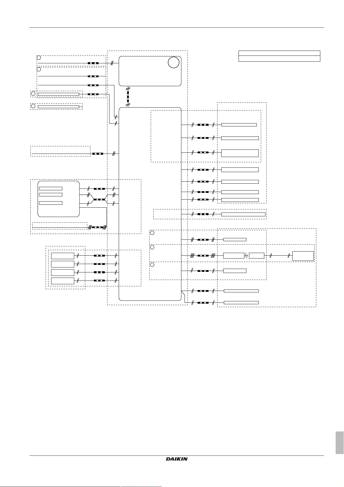
Electrical connection diagram
2x0.75
1
1
2
2
X1M: 1-2-3
X2M: 5-6
X5M: 9-10
A8P: X801M: 1-5
A8P: X801M: 2-5
A8P: X801M: 3-5
A8P: X801M: 4-5
A4P: Y1-YC
X2M: 7-9
A4P: X1-X2
X5M: 11-12
X2M: 1-2
X5M: 7-8
X5M: 5-6
X5M: 3-4
A4P: Y2-YC
X2M: 7-9
3
3
3
2x0.75
2x0.75
A15P: X1M: H-C-com
X2M: L-N
A2P: X1M: 1-3
A3P: X11M: 5-6
R2T
230 V
230 V
230 V
230 V
230 V
A2P: X1M: C-com-H
X1M: 1-2-3
4D112068B
X15M: 1-2
(EKLBUHCB6W1)
X15M: 8-9-10
X15M: 6-7
X5M: 1-2
X3M: 3-4-5
X3M: 1-2
- In case of signal cable: keep minimum distance to power cables >5 cm
Notes:
Field supply
Only for KRCS01-1 or EKRSCA1
2-way valve
signal
2 core
signal
2 core
signal
2 core
signal
2 core
signal
2 core
F1B:
L1-L2-L3-N + PE
or L-N + PE
5 core
Power limitation
demand input 4
Power limitation
demand input 3
Power limitation
demand input 2
Power limitation
demand input 1
Thermistor
Step 1-2
Clixon Q1L
Field supply
Only for *KRP1AHTA
Only for *KRP1HB*
Field supply
Indoor unit
Cooling/heating
On/OFF output
Electricity meter pulse input 2
Electricity meter pulse input 1
external thermistor (indoor or outdoor)
Circulation pump for DHW
M2S for cooling mode
Ext. heat source (e.g. boiler)
Alarm indication
2 core
2 core
signal
2 core
signal
signal
2 core
2 core
2 core
signal
2 core
2 core
External sensor
(floor or ambient)
Only for *KRTETS
signal
2 core
(3m included)
A13P: P1-P2 LAN adapter
A14P: P1-P2 user interface
Only for
(heat pump convector)
Only for EKRUDAS
Only for *KRTR
(wireless room thermostat)
Only for *KRTW
(wired room thermostat)
5 core for C/H operation
4 core for H only operation
3 core for C/H operation
2 core for H only operation
communication
2 core
communication
2 core
2 core
Optional part
External room thermostat / Heat pump convector
(main and/or additional zone)
main: X2M: 30-35
add: X2M: 30-35a
main: X2M: 30-31-34-35
add: X2M: 30-31-34a-35a
main: X2M: 30-34-35
add: X2M: 30-34a-35a
Cooling/heating
On/OFF output
NO valve: X2M: 21-28
NC valve: X2M: 21-29
Changeover to
ext. heat source output
Alarm output
3 core
3 core
3 core
2 core
2 core
X1M: L-N-earth
Normal kWh rate power supply for indoor unit: 230 V
Safety thermostat Q4L
Preferential kWh rate power supply contact
unit preferential kWh rate power supply:
230 V + earth
Only for preferential kWh rate power supply installation
unit power supply: 230 V + earth
Only for normal power supply installation
Outdoor unit
Standard part
Power supply
3 core
X8M: L-N-earth
Anti-legionella heater power supply (2, 4 kW): 230 V + earth
Power supply
3-5 core
Backup heater power supply (6 kW): 400 V or 230 V + earth
Power supply
Backup heater option
signal
signal
signal
For more details, please check the unit wiring.
14 Technical data
ERGA04~08DAV3(A) + EHVH04+08S23DAV
Daikin Altherma – Low temperature split
4P499573-1A – 2018.11
Installer reference guide
93
Page 94

14 Technical data
14.5 Table 1 – Maximum refrigerant charge allowed in a room: indoor unit
A
(m2) Maximum refrigerant charge in a room
room
1 0.138
2 0.276
3 0.414
4 0.553
5 0.691
6 0.829
7 0.907
8 0.970
9 1.028
10 1.084
11 1.137
12 1.187
13 1.236
14 1.283
15 1.328
16 1.371
17 1.413
18 1.454
19 1.494
20 1.533
21 1.571
22 1.608
23 1.644
24 1.679
25 1.714
26 1.748
27 1.781
28 1.814
29 1.846
30 1.877
31 1.909
(m
) (kg)
max
H=600mm
INFORMATION
▪ For floorstanding models, the value of "Installation
height (H)" is considered 600 mm to comply to
IEC60335-2-40:2013 A1 2016 Clause GG2.
▪ For intermediate mc values (i.e. when mc is between
two values from the table), consider the value that
corresponds to the higher mc value from the table. If
mc=1.87 kg, consider the value that corresponds to
"mc=1.88kg".
▪ Systems with a total refrigerant charge (mc) <1.84 kg
(i.e. if the piping length is <27 m) are NOT subjected to
any requirements to the installation room.
▪ Charges >1.9kg are NOT allowed in the unit.
14.7 Table 3 – Minimum venting opening area for natural ventilation: indoor unit
mcm
1.9 0.1 1.80 729
1.9 0.3 1.60 648
1.9 0.5 1.40 567
1.9 0.7 1.20 486
1.9 0.9 1.00 418
1.9 1.1 0.80 370
1.9 1.3 0.60 301
1.9 1.5 0.40 216
1.9 1.7 0.20 115
dm=mc–m
max
INFORMATION
▪ For floorstanding models, the value of "Installation
height (H)" is considered 600 mm to comply to
IEC60335-2-40:2013 A1 2016 Clause GG2.
▪ For intermediate dm values (i.e. when dm is between
two dm values from the table), consider the value that
corresponds to the higher dm value from the table. If
dm=1.55 kg, consider the value that corresponds to
"dm=1.6kg".
(kg) Minimum venting opening area
max
(cm2)
H=600mm
INFORMATION
▪ For floorstanding models, the value of "Installation
height (H)" is considered 600 mm to comply to
IEC60335-2-40:2013 A1 2016 Clause GG2.
▪ For intermediate A
between two values from the table), consider the value
that corresponds to the lower A
If A
=12.5m2, consider the value that corresponds to
room
"A
=12m2".
room
values (i.e. when A
room
value from the table.
room
14.6 Table 2 – Minimum floor area: indoor unit
mc (kg) Minimum floor area (m²)
H=600mm
1.84 28.81
1.86 29.44
1.88 30.08
1.90 30.72
Installer reference guide
94
room
is
ERGA04~08DAV3(A) + EHVH04+08S23DAV
Daikin Altherma – Low temperature split
4P499573-1A – 2018.11
Page 95
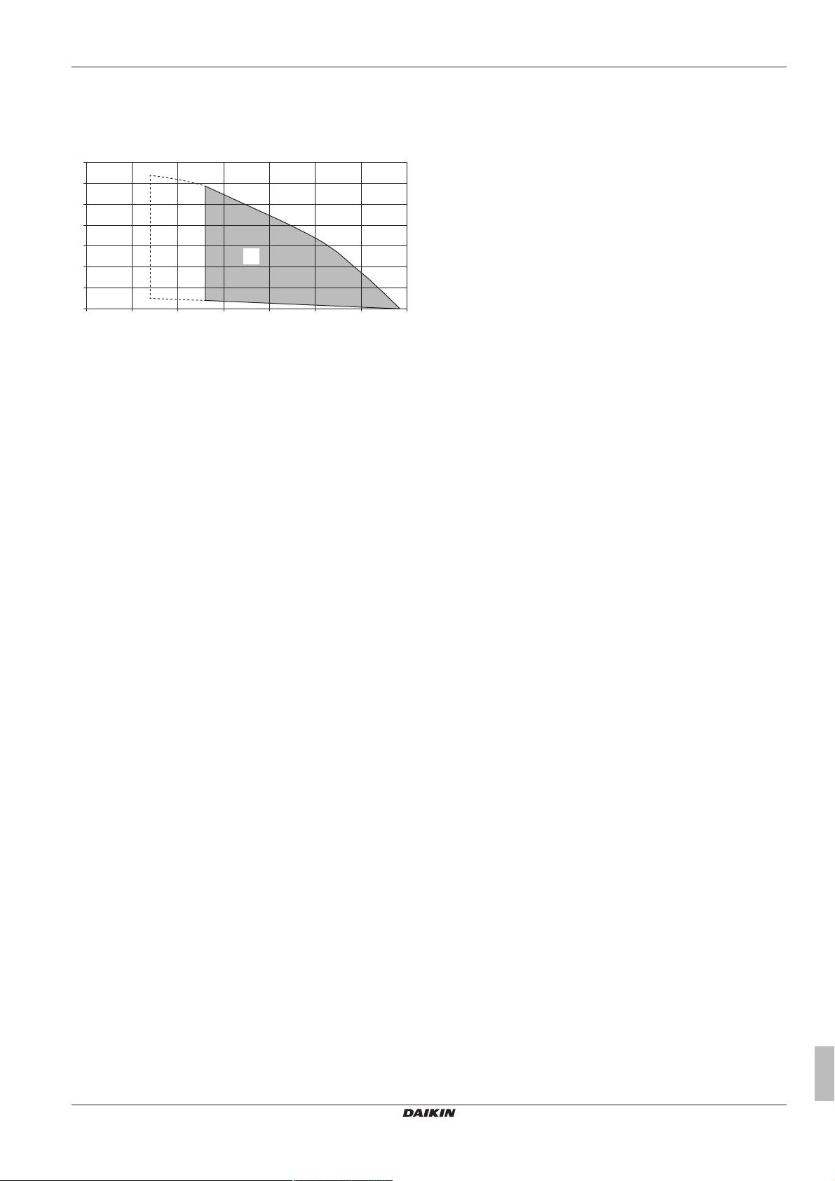
15 Glossary
0
0 5 10 15 20 25 30
35
20
30
C
40
50
60
70
10
4D112012
B (l/min)
A (kPa)
14.8 ESP curve: Indoor unit
Note: A flow error will occur when the minimum water flow rate is not
reached.
A External static pressure in the space heating/cooling circuit
B Water flow rate through the unit in the space heating/
cooling circuit
C Operation range
Dashed lines: Operation area is extended to lower flow rates only in
case the unit operates with heat pump only. (Not in startup, no
backup heater operation, no defrost operation.)
Notes:
▪ Selecting a flow outside the operating area can damage the unit or
cause the unit to malfunction. See also the minimum and
maximum allowed water flow range in the technical specifications.
▪ Water quality must be according to EU directive 98/83EC.
Accessories
Labels, manuals, information sheets and equipment that are
delivered with the product and that need to be installed
according to the instructions in the accompanying
documentation.
Optional equipment
Equipment made or approved by Daikin that can be
combined with the product according to the instructions in
the accompanying documentation.
Field supply
Equipment NOT made by Daikin that can be combined with
the product according to the instructions in the
accompanying documentation.
15 Glossary
Dealer
Sales distributor for the product.
Authorized installer
Technical skilled person who is qualified to install the
product.
User
Person who is owner of the product and/or operates the
product.
Applicable legislation
All international, European, national and local directives,
laws, regulations and/or codes that are relevant and
applicable for a certain product or domain.
Service company
Qualified company which can perform or coordinate the
required service to the product.
Installation manual
Instruction manual specified for a certain product or
application, explaining how to install, configure and maintain
it.
Operation manual
Instruction manual specified for a certain product or
application, explaining how to operate it.
Maintenance instructions
Instruction manual specified for a certain product or
application, which explains (if relevant) how to install,
configure, operate and/or maintain the product or
application.
ERGA04~08DAV3(A) + EHVH04+08S23DAV
Daikin Altherma – Low temperature split
4P499573-1A – 2018.11
Installer reference guide
95
Page 96

1/9
Field settings table
[8.7.5] = .... 7401
Applicable indoor units
EHVH04S23DAV*
EHVH08S23DAV*
Notes
4P499575-1A - 2017.11
Page 97

2/9
Breadcrumb Field code Setting name Range, step
Default valu
e
Date Value
Room
└─ Antifrost
1.4.1 [2-06] R/W 0: Disabled
1: Enabled
1.4.2 [2-05] R/W 4~16°C, step: 1°C
16°C
└─ Setpoint range
1.5.1 [3-07] R/W 12~18°C, step: 0,5°C
12°C
1.5.2 [3-06] R/W 18~30°C, step: 0,5°C
30°C
Room
1.6 [2-09] R/W -5~5°C, step: 0,5°C
0°C
1.7 [2-0A] R/W -5~5°C, step: 0,5°C
0°C
Main zone
2.4 0: Fixed
2: Weather de
p
enden
t
└─ Heating WD curve
2.5 [1-00] R/W -40~5°C, step: 1°C
-10°C
2.5 [1-01] R/W 10~25°C, step: 1°C
15°C
2.5 [1-02] R/W
[9-01]~[9-00], step: 1°C
35°C
2.5 [1-03] R/W [9-01]~min(45, [9-00])°C , step: 1°C
25°C
Main zone
2.7 [2-0C] R/W
0: Underfloor heating
1: Fancoil unit
2: Radiator
└─ Setpoint range
2.8.1 [9-01] R/W 15~37°C, step: 1°C
25°C
2.8.2 [9-00] R/W [2-0C]=2:
37~65, step: 1°C
55°C
[2-0C]≠2:
37~55, step: 1°C
55°C
Main zone
2.9 [C-07] R/W
0: LWT control
1: Ext RT control
2: RT control
2.A [C-05] R/W 0: 1: 1 contact
2: 2 contacts
└─ Delta T
2.B.1 [1-0B] R/W 3~10°C, step: 1°C
5°C
└─ Modulation
2.C.1 [8-05] R/W
0: No
1: Yes
2.C.2 [8-06] R/W 0~10°C, step: 1°C
5°C
└─ Shut off valve
2.D.1 [F-0B] R/W
0: No
1: Yes
Additional zone
3.4 0: Fixed
2: Weather de
p
enden
t
└─ Heating WD curve
3.5 [0-00] R/W [9-05]~min(45,[9-06])°C, step: 1°C
35°C
3.5 [0-01] R/W [9-05]~[9-06]°C, step: 1°C
50°C
3.5 [0-02] R/W 10~25°C, step: 1°C
15°C
3.5 [0-03] R/W -40~5°C, step: 1°C
-10°C
Additional zone
3.7 [2-0D] R/W
0: Underfloor heating
1: Fancoil unit
2: Radiator
└─ Setpoint range
3.8.1 [9-05] R/W 15~37°C, step: 1°C
25°C
3.8.2 [9-06] R/W [2-0D]=2:
37~65, step: 1°C
55°C
[2-0D]≠2:
37~55, step: 1°C
55°C
Additional zone
3.A [C-06] R/W 0: 1: 1 contact
2: 2 contacts
└─ Delta T
3.B.1 [1-0C] R/W 3~10°C, step: 1°C
5°C
Space heating / cooling
└─ Operation range
4.3.1 [4-02] R/W 14~35°C, step: 1°C
22°C
Space heating / cooling
4.4 [7-02] R/W
0: 1 LWT zone
1: 2 LWT zones
4.5 [F-0D] R/W 0: Continuous
1: Sample
2: Re
q
uest
4.6 [E-02] R/O
1: Heating onl
y
Setpoint mode
Installer setting at variance with
default value
Emitter type
Heating minimum
Leaving water value for low ambient temp. for LWT main zone heating WD curve.
Leaving water value for high ambient temp. for LWT main zone heating WD curve.
Activation
Room sensor offset
Room sensor offset
Room setpoint
Heating minimum
Space heating OFF temp
Number of zones
Thermostat type
Delta T heating
During thermo
Thermostat type
Emitter type
Leaving water value for low ambient temp. for LWT add zone heating WD curve.
Delta T heating
Field settings table
High ambient temp. for LWT main zone heating WD curve.
Modulation
Max modulation
Heating minimum
Heating maximum
Setpoint mode
Low ambient temp. for LWT add zone heating WD curve.
High ambient temp. for LWT add zone heating WD curve.
Control
Leaving water value for high ambient temp. for LWT add zone heating WD curve.
Heating maximum
Heating maximum
Low ambient temp. for LWT main zone heating WD curve.
Unit type
Pump operation mode
4P499575-1A - 2017.11 (#) Setting is not applicable for this unit.
Page 98

3/9
Breadcrumb Field code Setting name Range, step
Default valu
e
Date Value
Installer setting at variance with
default value
Field settings table
4.7 [9-0D] R/W 0~8, step:1
0 : No limitation
1~4 : 50~80%
5~8 : 50~80% during sampling
6
Space heating / cooling
4.9 [F-00] R/W
0: Restricted
1: Allowed
4.A [D-03] R/W 0: No
1: increase 2°C, span 4°C
2: increase 4°C, span 4°C
3: increase 2°C, span 8°C
4: increase 4°C, span 8°C
4.B [9-04] R/W 1~4°C, step: 1°C
1°C
4.C [2-06] R/W 0: Disabled
1: Enabled
Tank
5.2 [6-0A] R/W 30~[6-0E]°C, step: 1°C
60°C
5.3 [6-0B] R/W 30~min(50, [6-0E])°C, step: 1°C
45°C
5.4 [6-0C] R/W 30~min(50, [6-0E])°C, step: 1°C
45°C
5.6 [6-0D] R/W 0: Reheat only
1: Reheat + sched.
2: Scheduled onl
y
└─ Disinfection
5.7.1 [2-01] R/W 0: No
1: Yes
5.7.2 [2-00] R/W 0: Each day
1: Monday
2: Tuesday
3: Wednesday
4: Thursday
5: Friday
6: Saturday
7: Sunda
y
5.7.3 [2-02] R/W 0~23 hour, step: 1 hour
1
5.7.4 [2-03] R/O 55~75°C, step: 5°C
70°C
5.7.5 [2-04] R/W 5~60 min, step: 5 min
10 min
Tank
5.8 [6-0E] R/W 40~65°C, step: 1°C
65°C
5.9 [6-00] R/W 2~40°C, step: 1°C
25°C
5.A [6-08] R/W
2~20°C, step: 1°C
10°C
5.B R/W
0: Fixed
1: Weather de
p
endent
└─ WD curve
5.C [0-0B] R/W 35~[6-0E]°C, step: 1°C
55°C
5.C [0-0C] R/W 45~[6-0E]°C, step: 1°C
65°C
5.C [0-0D] R/W 10~25°C, step: 1°C
15°C
5.C [0-0E] R/W -40~5°C, step: 1°C
-10°C
Tank
5.D [6-01] R/W 0~10°C, step: 1°C
2°C
User settings
└─ Quiet
7.4.1 R/W
0: OFF
1: Quiet
2: More quiet
3: Most quiet
4: Automatic
└─ Electricity price
7.5.1 R/W 0,00~990/kWh
1/kWh
7.5.2 R/W 0,00~990/kWh
1/kWh
7.5.3 R/W 0,00~990/kWh
1/kWh
User settings
7.6 R/W 0,00~990/kWh
0,00~290/MBtu
1,0/kWh
Installer settings
└─ Configuration wizard
└─ System
9.1 [E-03] R/W
0: No heater
1: External heater
2: 3V
3: 6V
4: 9W
9.1 [E-05]
[E-06]
[E-07]
R/O
3: Integrated
9.1 [4-06] R/W
0: Manual
1: Automatic
9.1 [7-02] R/W
0: Single zone
1: Dual zone
└─ Backup heater
9.1 [5-0D] R/O 0~2
0: 230V, 1~
Duration
Tank setpoint
Hysteresis
Hysteresis
Setpoint mode
Leaving water value for high ambient temp. for DHW WD curve.
Leaving water value for low ambient temp. for DHW WD curve.
BUH type
Low ambient temp. for DHW WD curve.
Gas price
Pump limitation
Overshoot
Maximum
Heat up mode
Reheat setpoint
Eco setpoint
Comfort setpoint
Start time
Pump outside range
Antifrost
Increase around 0°C
Operation day
High ambient temp. for DHW WD curve.
Emergency
Margin
Activation
High
Medium
Low
Domestic hot water
Number of zones
Voltage
Activation
(#) Setting is not applicable for this unit. 4P499575-1A - 2017.11
Page 99

4/9
Breadcrumb Field code Setting name Range, step
Default valu
e
Date Value
Installer setting at variance with
default value
Field settings table
9.1 [4-0A] R/O 0~3
0: 1
9.1 [6-03] R/W 0~10kW, step: 0,2kW
3kW
9.1 [6-04] R/O 0~10kW, step: 0,2kW
3kW
└─ Main zone
9.1 [2-0C] R/W
0: Underfloor heating
1: Fancoil unit
2: Radiator
9.1 [C-07] R/W
0: LWT control
1: Ext RT control
2: RT control
9.1 R/W 0: Fixed
2: Weather de
p
enden
t
9.1 R/W
0: No
1: Yes
9.1 [1-00] R/W -40~5°C, step: 1°C
-10°C
9.1 [1-01] R/W 10~25°C, step: 1°C
15°C
9.1 [1-02] R/W
[9-01]~[9-00], step: 1°C
35°C
9.1 [1-03] R/W [9-01]~min(45, [9-00])°C , step: 1°C
25°C
9.1 [1-06]
20
9.1 [1-07]
35
9.1 [1-08]
22
9.1 [1-09]
18
└─ Additional zone
9.1 [2-0D] R/W
0: Underfloor heating
1: Fancoil unit
2: Radiator
9.1 R/W 0: Fixed
2: Weather de
p
enden
t
9.1 R/W
0: No
1: Yes
9.1 [0-00] R/W [9-05]~min(45,[9-06])°C, step: 1°C
35°C
9.1 [0-01] R/W [9-05]~[9-06]°C, step: 1°C
50°C
9.1 [0-02] R/W 10~25°C, step: 1°C
15°C
9.1 [0-03] R/W -40~5°C, step: 1°C
-10°C
9.1 [0-04]
8
9.1 [0-05]
12
9.1 [0-06]
35
9.1 [0-07]
20
└─ Tank
9.1 [6-0D] R/W 0: Reheat only
1: Reheat + sched.
2: Scheduled onl
y
9.1 [6-0A] R/W 30~[6-0E]°C, step: 1°C
60°C
9.1 [6-0B] R/W 30~min(50, [6-0E])°C, step: 1°C
45°C
9.1 [6-0C] R/W 30~min(50, [6-0E])°C, step: 1°C
45°C
└─ Domestic hot water
9.2.1 [E-05]
[E-06]
[E-07]
R/O
3: Integrated
9.2.2 [D-02] R/W
0: No
1: Secondary rtrn
2: Disinf. Shunt
9.2.4 [D-07] R/W
0: No
1: Yes
└─ Back up heater
9.3.1 [E-03] R/W
0: No heater
1: External heater
2: 3V
3: 6V
4: 9W
9.3.2 [5-0D] R/O 0~2
0: 230V, 1~
9.3.3 [4-0A] R/O 0~3
0: 1
9.3.4 [6-03] R/W 0~10kW, step: 0,2kW
3kW
9.3.5 [6-04] R/O 0~10kW, step: 0,2kW
3kW
9.3.6 [5-00] R/W 0: Allowed
1: Not allowe
d
9.3.7 [5-01] R/W -15~35°C, step: 1°C
0°C
9.3.8 [4-00] R/W 0: Disabled
1: Enabled
2: Onl
y
DHW
└─ Booster heater
9.4.1 [6-02] R/W 0~10kW, step: 0,2kW
2,4kW
9.4.3 [8-03] R/W 20~95 min, step: 5 min
50 min
9.4.4 [4-03] R/W 0: Restricted
1: Allowed
2: Overlap
3: Compressor off
4: Le
g
ionella onl
y
Configuration
Capacity step 1
Additional capacity step 2
Emitter type
Leaving water value for high ambient temp. for LWT main zone heating WD curve.
--
Control
Setpoint mode
Schedule
--
--
Low ambient temp. for LWT main zone heating WD curve.
High ambient temp. for LWT main zone heating WD curve.
Leaving water value for low ambient temp. for LWT main zone heating WD curve.
--
Leaving water value for high ambient temp. for LWT add zone heating WD curve.
Leaving water value for low ambient temp. for LWT add zone heating WD curve.
High ambient temp. for LWT add zone heating WD curve.
Low ambient temp. for LWT add zone heating WD curve.
Schedule
Emitter type
Setpoint mode
--
--
--
--
Heat up mode
Comfort setpoint
Eco setpoint
Reheat setpoint
Domestic hot water
DHW pump
Solar
BUH type
Voltage
Configuration
Capacity step 1
Additional capacity step 2
Equilibrium
Equilibrium temperature
Operation
Capacity
BSH eco timer
Operation
4P499575-1A - 2017.11 (#) Setting is not applicable for this unit.
Page 100

5/9
Breadcrumb Field code Setting name Range, step
Default valu
e
Date Value
Installer setting at variance with
default value
Field settings table
Installer settings
9.5 [4-06] R/W
0: Manual
1: Automatic
└─ Balancing
9.6.1 [5-02] R/W
0: Disabled
1: Enabled
9.6.2 [5-03] R/W -15~35°C, step: 1°C
0°C
9.6.3 [5-04] R/W 0~20°C, step: 1°C
10°C
9.6.4 [8-02] R/W 0~10 hour, step: 0,5 hour
3 hours
9.6.5 [8-00] R/W
0~20 min, step 1 min
1 min
9.6.6 [8-01] R/W 5~95 min, step: 5 min
30 min
9.6.7 [8-04] R/W 0~95 min, step: 5 min
95 min
Installer settings
9.7 [4-04]
0: Intermittent
1: Continuous
2: Off
└─ Benefit kWh power supply
9.8.1 [D-01] R/W
0: No
1: Active open
2: Active closed
3: Safet
y
thermostat
9.8.2 [D-00] R/W
0: None
1: BSH only
2: BUH only
3: All heaters
9.8.3 [D-05] R/W 0: Forced off
1: As normal
└─ Power consumption control
9.9.1 [4-08] R/W
0: No limitation
1: Continuous
2: Di
g
ital inputs
9.9.2 [4-09] R/W 0: Current
1: Powe
r
9.9.3 [5-05] R/W 0~50 A, step: 1 A
50
A
9.9.4 [5-05] R/W 0~50 A, step: 1 A
50
A
9.9.5 [5-06] R/W 0~50 A, step: 1 A
50
A
9.9.6 [5-07] R/W 0~50 A, step: 1 A
50
A
9.9.7 [5-08] R/W 0~50 A, step: 1 A
50
A
9.9.8 [5-09] R/W 0~20 kW, step: 0,5 kW
20 kW
9.9.9 [5-09] R/W 0~20 kW, step: 0,5 kW
20 kW
9.9.A [5-0A] R/W 0~20 kW, step: 0,5 kW
20 kW
9.9.B [5-0B] R/W 0~20 kW, step: 0,5 kW
20 kW
9.9.C [5-0C] R/W 0~20 kW, step: 0,5 kW
20 kW
9.9.D [4-01]
0: None
1: BSH
2: BUH
└─ Energy metering
9.A.1 [D-08] R/W
0: No
1: 0,1 pulse/kWh
2: 1 pulse/kWh
3: 10 pulse/kWh
4: 100 pulse/kWh
5: 1000
p
ulse/kWh
9.A.2 [D-09] R/W
0: No
1: 0,1 pulse/kWh
2: 1 pulse/kWh
3: 10 pulse/kWh
4: 100 pulse/kWh
5: 1000
p
ulse/kWh
└─ Sensors
9.B.1 [C-08] R/W
0: No
1: Outdoor sensor
2: Room sensor
9.B.2 [2-0B] R/W -5~5°C, step: 0,5°C
0°C
9.B.3 [1-0A] R/W
0: No averaging
1: 12 hours
2: 24 hours
3: 48 hours
4: 72 hours
└─ Bivalent
9.C.1 [C-02] R/W
0: No
1: Bivalent
9.C.2 [7-05] R/W
0: Very high
1: High
2: Medium
3: Low
4: Ver
y
low
9.C.3 [C-03] R/W -25~25°C, step: 1°C
0°C
9.C.4 [C-04] R/W 2~10°C, step 1°C
3°C
Installer settings
9.D [C-09] R/W
0: Normally open
1: Normall
y
closed
9.E [3-00] R/W 0: No
1: Yes
Ext. amb. sensor offset
Emergency
Space heating priority
Priority temperature
Offset BSH setpoint
Anti-recycle timer
Minimum running timer
Maximum running timer
Additional timer
Water pipe freeze prevention
Benefit kWh power supply
Allow heater
Allow pump
Power consumption control
Type
Limit
Limit 1
Limit 2
Limit 3
Limit 4
Limit
Limit 1
Limit 2
Limit 3
Limit 4
Priority heater
Electricity meter 1
Electricity meter 2
External sensor
Averaging time
Bivalent
Boiler efficiency
Temperature
Hysteresis
Alarm output
Auto restart
(#) Setting is not applicable for this unit. 4P499575-1A - 2017.11
 Loading...