


DE12, DE12T &
DE12TI & DE12TIS
DIESEL ENGINE
Shop Manual
65.99892-8030B
Daewoo reserves the righ t to improve our products in a continuing proc ess to provide the best possible
product to the mar ket place. These improvements can be implem ented at any time with no obligation t o
change materials on previously sold products. It is recommended that consumers periodically contact their
distributors for recent documentation on purchased equipment.
This documentation may include attachments and optional equipment that is not available in your
machine’s package. Please call your distributor for additional items that you may require.
Illustrations used throughout this manual are used only as a representation of the actual piece of
equipment, and may vary from the actual item.
65.99892-8030B Shop Manual

FOREWORD
This manual has been prepared to help you use and maintain the DE series diesel engines (DE12,
DE12T, DE12TI and DE12TIS) safely and correctly.
These economical and high-performance diesel engines(6 cylinders, 4 strokes, in-line, direct injection
type) have been designed and manufactured to be used for overland transport or industrial purpose. They meet all the requirements such as low noise, fuel economy, high engine speed and
durability.
Nonetheless, to obtain the best performance and long life of an engine, it is essential to operate it
appropriately and to carry out periodic checks as instructed in this manual. You are requested to
thoroughly read this manual from cover to cover and to acquaint yourself with all the information
contained in this manual.
All information, illustration and specifications continued in this literature are based on the latest
product information available at the time of publication approval. The right is reserved to make
changes at any time without notice.
Please contact Daewoo dealer for the answers to any questions you may have about DE series
engine's features, operation or manuals.

CONTENTS
1. General information
...............................................................................................................
1
1.1. Engine characteristics 1.4. Engine performance curve
1.2. Main data and specifications 1.5. Exterior view of engine
1.3. Engine specification(’98 type)
2. Major maintenance
.............................................................................................................. 22
2.1. Preventive maintenance 2.2. Diagnostics and troubleshooting
for the engine
3. Disassembly and reassembly of major components
....................................................... 37
3.1. Disassembly 3.3. Reassembly
3.2. Inspection 3.4. Breaking-in
4. Maintenance of major components
.................................................................................... 79
4.1. Cooling system 4.3. Fuel system
4.2. Lubricating system 4.4. Turbocharger
5. Scan pole diagnosis for DE12TIS
..................................................................................... 142
5.1. Wire harness connection 5.4. Sensor data
5.2. System & Vehicle selection 5.5. Actuator test
5.3. Self-diagnosis(current) 5.6. Flight record
6. Maintenance specifications
............................................................................................... 154
6.1. Tightening torque 6.2. Maintenance specification table
¥
WORLDWIDE NETWORK
1. General information
1.1. Engine characteristics
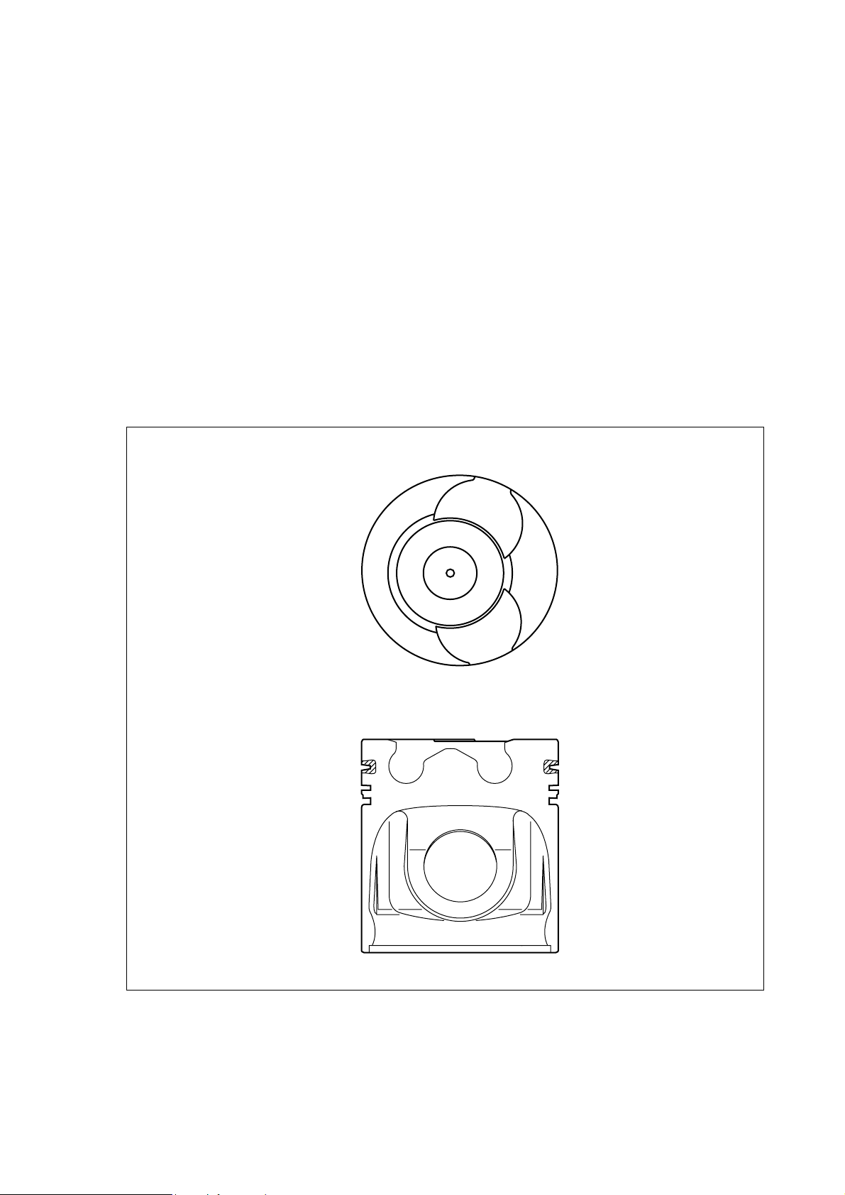
1.1.1. OMEGA combustion bowl
The OMEGA combustion bowl is a unit designed to perform high-efficiency, low- emission
combustion. As the rim around the combustion bowl port of the upper of the piston has been
machined in a smaller size than the interior of the combustion bowl, strong swirl is produced
in the combustion bowl and strong squish flow makes the fuel be mixed more sufficiently with
air.
Due to the application of OMEGA combustion system and optimal ultilization of intake and
exhaust port configuration within the cylinder head, the DE12 series engines discharge a
very low level of hazardous exhaust gases such as smoke, nitrogen oxide, hydrocarbon, or
carbon monoxide and thus ensure high performance and low fuel consumption.
- 1 -
EA2M1001
<Figure. 1-1> OMEGA combustion bowl
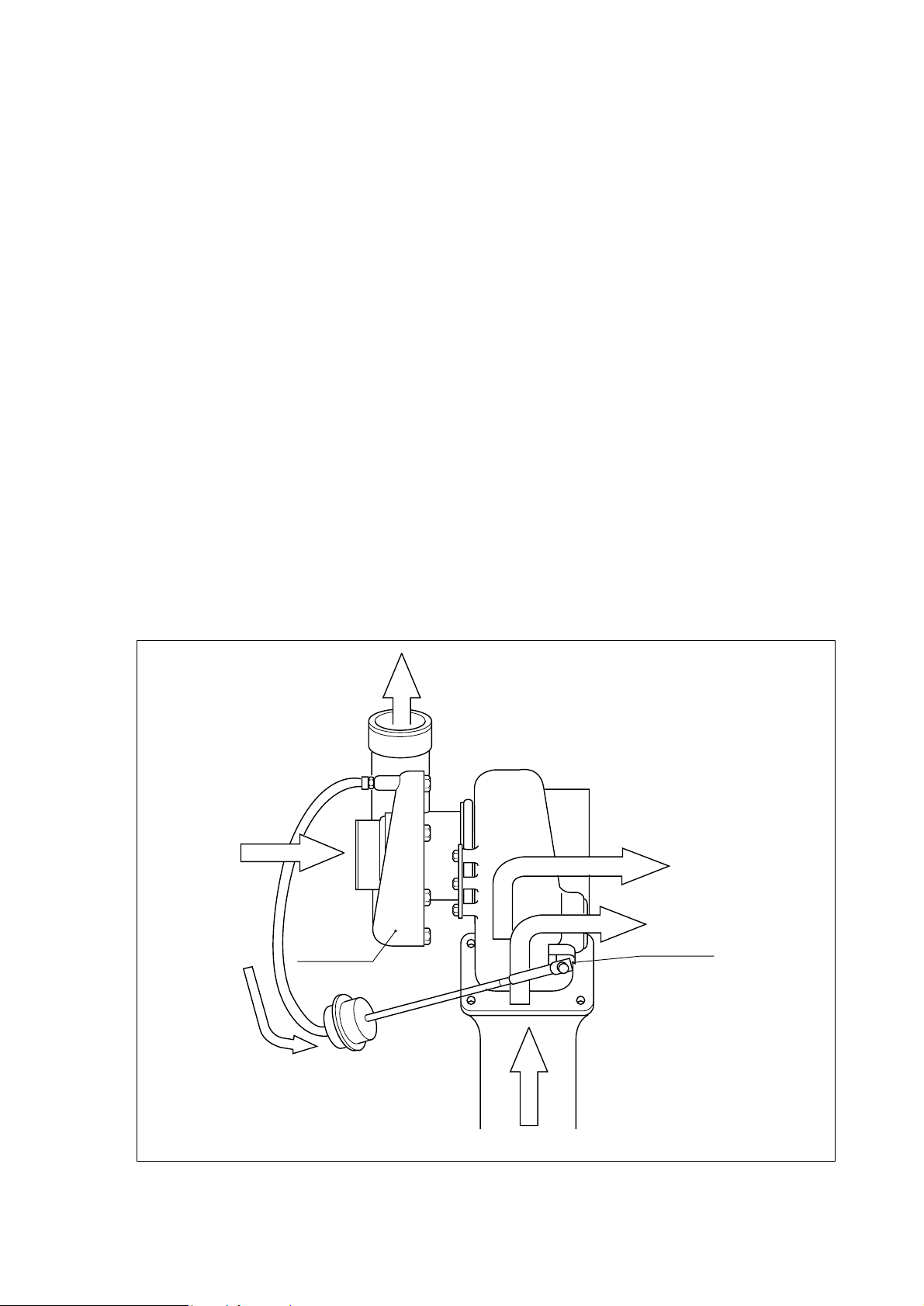
1.1.2. Wastegated turbocharging system
1) What is the wastegated turbocharging system?
Turbocharger is a system designed to pressurize the intake air to increase engine output and
decrease fuel consumption by using the energy of exhaust gas discharged from the engine.
However, the turbocharger has a weak point at low engine speed, its performance may drop,
thus performance at low speed is relatively low.
The WASTEGATED TURBOCHARGING SYSTEM is an up-to-date turbocharging system
remedying such a defect, and the working principle is as follows:
A small-sized high performance turbine is used to improve engine performance at low
speeds. As high charging efficiency can be obtained even If a small amount of exhaust gas
is present at low speed. On the other hand, if higher charging pressure is produced than
what is present at high speed, fuel consumption increases. To correct this, part of exhaust
gas is forced to be discharged into the exhaust manifold through the waste gate, not through
the turbine.
The waste gate is controlled by the ACTUATOR mounted in the turbocharger, and if the
pressure in the turbocharger becomes higher than what is required for the engine, the waste
gate is forced to open.
2) DE12T, DE12TI and DE12TIS engines are featured by the application of turbochager so that
the torque in low speeds can be increased by 30% or more, not only to create high performance, just from the time of starting off the vehicle but also to greatly reduce fuel consumption.
- 2 -
Compressed air outlet por
Intake air
Turbine
Turbine port
Exhaust gas
outlet port
Waste gate
Compressor
Actuator
EQM1003I
<Figure 1-3> Turbochager
1.2. Main data and specifications
Engine Model DE12 DE12T DE12TI DE12TIS
Type In-line, 4-stroke, vertical type
Combustion chamber type
OMEGA Combustion bowl
Fuel injection Direct injection type
BoreB stroke-No. of cylinders
123mm B 155 - 6
Total displacement 11,051cc
Compression ratio 17.1:1 17.1:1 16.5:1 16.8
Maximum power(PS) 225 ps/2,200 rpm 300 ps/2,200 rpm 340 ps/2,100 rpm
Maximum torque 81.5 kg.m/1,400 rpm 110 kg.m/1,300 rpm 135 kg.m/1,260 rpm
Injection timing 12° BTDC 9° BTDC 12° BTDC 1.0° BTDC
Firing order 1-5-3-6-2-4
Injection pump type S3000 S3000 S3S HD-TICS
Governor type RFD-C/RLD RFD-C RFD-D RLD-J
Timer type SP SP SPG Electronically control
Nozzle type
Multi-hole type(5-N0.29) Multi-hole type(5-N0.31) Multi-hole type(5-N0.33) Multi-hole type(5-N0.29)
Feed pump type K-P K-P K-PS
Valve Timing
Intake valve open at BTDC 18° BTDC 18°
Intake valve close at ABDC 34° ABDC 32°
Exhaust valve open at BBDC 46° BBDC 70°
Exhaust valve close at ATDC 14° ATDC 30°
Oil pump type Gear type
Oil cooler type Water-cooler
Fuel filter type Full flow type
Oil capacity 20M(Oil pan 17M)
Coolant capacity 19M
Thermostat type Wax-pallet
Starter : Voltage-output 24V-6.0Kw
Alternator : Voltage-capacity
24V-45A
- 3 -
1.3. Engine specification(’98 type)
- 4 -
Item DE12-228 DE12TI-280 DE12TI-310 DE12TIS
Manufacturer DHI
Mounting location Under Seat
Starting type SELF
Engine type Diesel 4 Cycle
Turbocharged & Intercooled
Cylinder(No. arrangement) In-line, vertical
Combustion chamber type Direct injection
Valve position OHV
Diameter x stroke 123x155
Compression ratio 17.1 16.1 16.8
Comp. pressure(kg/cm2-rpm) 28-200
Average efficient comp.(kg/cm2) 9.27 13.08 14.21
Max. horse power(ps/rpm) 228/2,200 280/2,100 310/2,100 340/2,100
Max. torque(kg•m/rpm) 80/1,400 115/1,260 125/1,260 140/1,260
Firing order 1-5-3-6-2-4
Engine dimension(LxWxH) 1,317x747x1,015 1,317x847x1,064
Dry weight(kg) 872 909 910
Cycle 4
Piston Material AL
Comp. ring 2
Oil ring 1
Open BTDC 18° BTDC 18°
Close ABDC 34° ABDC 32°
Open BBDC 46° BBDC 70°
Close ATDC 14° ATDC 30°
Intake 0.3
Exhaust 0.3
Engine speed at no load 550~600
Lubricating Type
Forced pressure type
Oil pump type Gear
Oil filter type Strainer
Oil capacity(M)20
Oil cooler type Water cooled
Intake
Exhaust
No. of piston ring
Valve clearance
(cold engine)
Lubricatring
system
In. & Ex.
Valve
timing
E
n
g
i
n
e
- 5 -
Item DE12-228 DE12TI-280 DE12TI-310 DE12TIS
Turbocharger type -
Exhaust gas driven
Intercooler type - Air cooled
Cooling type
Forced water circulation
Coolant capacity 19(engine only)
Water pump type Centrifugal
Thermostat type Wax pellet
Fuel pump type Plunger
Fuel filter type Full flow
Fuel injection type Mechanical
Electronic control
Type Inline
Timing BTDC 8° BTDC 12° BTDC 1.0°
Plunger Dia. 12
Cam lift(mm) 11 12 14
Nozzle mounting Flange
Nozzle type Multi hole
Orifice
No 5
Dia.(mm) 0.29 0.33 0.29
Inj. pressure(kg/cm2) 220 130/220 163/224
Voltage(V) 24V
Type Electric
Voltage(V) - Amp(A) 22-120
Output(V-A) ---Regulator ---Type Reduction
Output(kW) 24V-6.0kW
Type
Air compression
Cooling
system
Engine
Fuel
system
Electric
system
Inj.
pump
system
Inj.
nozzle
Preheat
-ing
system
Alternator
Starter
Ignition
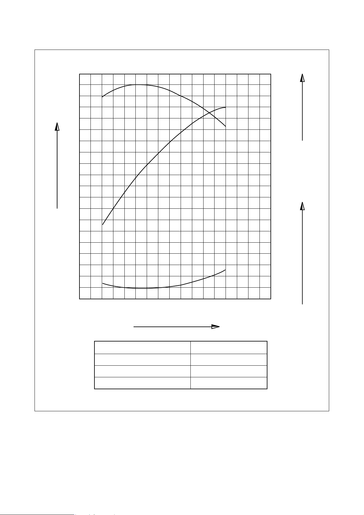
1.4. Engine performance curve
1.4.1. DE12
- 6 -
220
200
180
160
140
120
100
1000 1200 1400 1600 1800 2000 2200 2400
85
80
75
170
160
165
70
Performance criteria ISO 1585(SAE J1349)
Output(Max.) 235 ps/2,200 rpm
Torque(Max.) 81.5 kg.m/1,400 rpm
Fuel consumption ratio(min.) 160 g/ps.h
EQM1004I
Revolution(rpm)
Output(ps)
Torque(kg
.
m)Fuel consumption(g/ps
.
h)
- 7 -
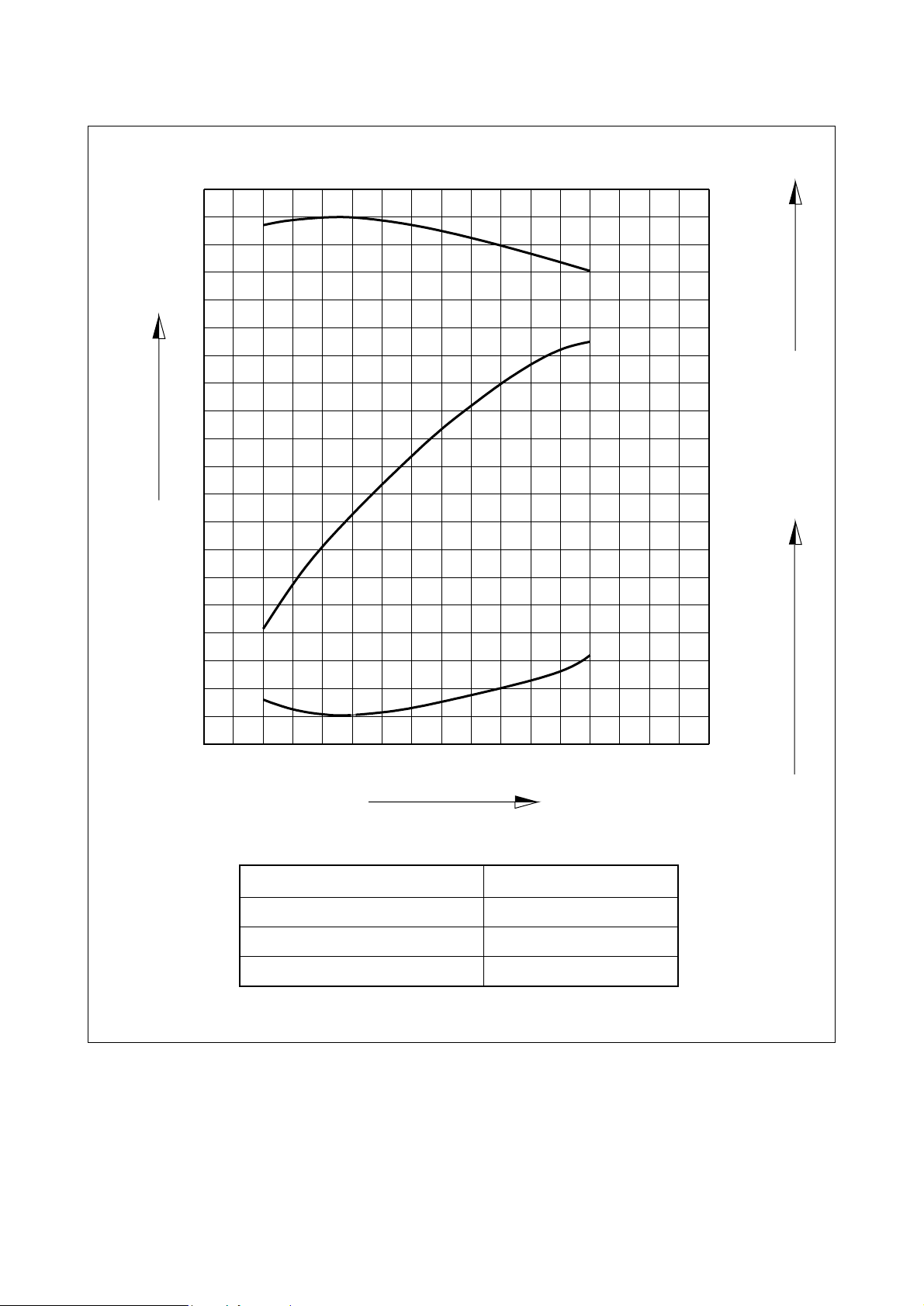
1.4.2. DE12(’98 type)
220
200
180
160
140
120
100
1000 1200 1400 1600 1800 2000 2200 2400
80
75
70
165
160
155
Performance ISO 1585(SAE J1349)
Output(Max.) 228 ps/2,200 rpm
Torque(Max.) 80 kg.m/1,400 rpm
Fuel consumption ratio(min.) 155 g/ps.h
EQM1005I
Revolution(rpm)
Output(ps)
Torque(kg
.
m)Fuel consumption(g/ps
.
h)
- 8 -
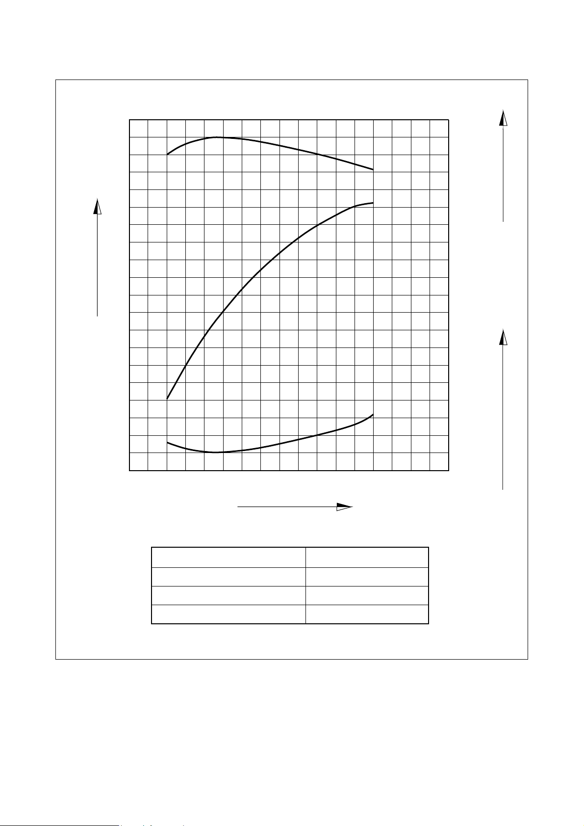
1.4.3. DE12T
155
160
165
170
90
80
100
110
1 000
1200
1400 1600 1800
2000
2200 2400
120
150
180
210
240
270
300
Performance ISO 1585(SAE J1349)
Output(Max.) 300 ps/2,200 rpm
Torque(Max.) 110 kg.m/1,300 rpm
Fuel consumption ratio(min.) 155 g/ps.h
EQM1006I
Revolution(rpm)
Output(ps)
Torque(kg
.
m)
Fuel consumption(g/ps
.
h)
- 9 -
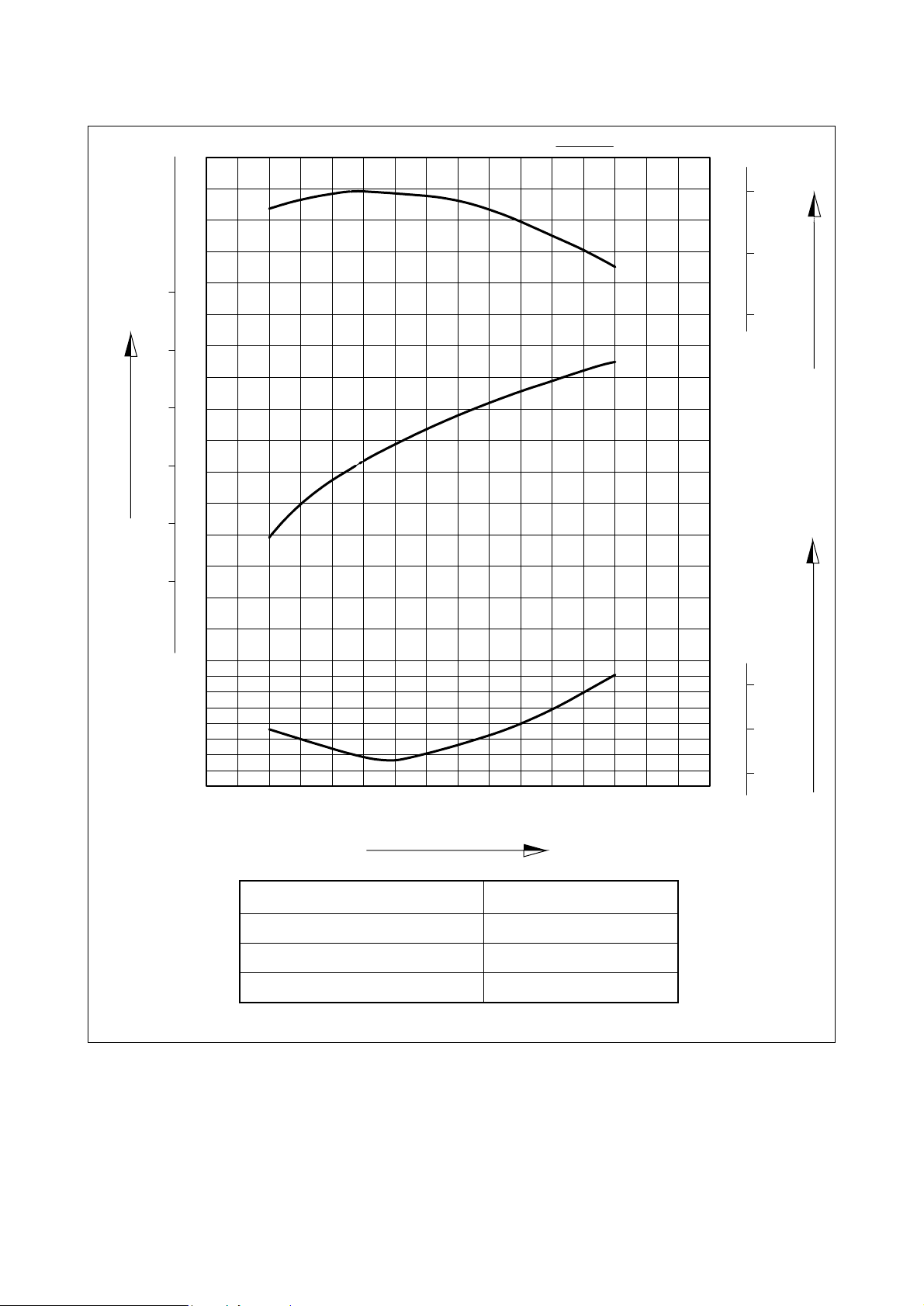
1.4.4. DE12TI
150
155
160
125
120
130
135
1 000
1200
1400 1600 1800
2000
2200 2400
160
190
220
250
280
310
340
Performance ISO 1585(SAE J1349)
Output(Max.) 340 ps/2,100 rpm
Torque(Max.) 135 kg.m/1,260 rpm
Fuel consumption ratio(min.) 147 g/ps.h
EQM1007I
Revolution(rpm)
Output(ps)
Torque(kg
.
m)
Fuel consumption(g/ps
.
h)
- 10 -
1.4.5. DE12TI(280 ps : ’98 type)
300
220
220
180
1000 1200 1600 1800 2000 2200 2400
145
150
155
115
105
95
1400
140
260
Performance ISO 1585(SAE J1349)
Output(Max.) 280 ps/2,100 rpm
Torque(Max.) 115 kg.m/1,260 rpm
Fuel consumption ratio(min.) 145 g/ps.h
EQM1008I
Revolution(rpm)
Output(ps)
Torque(kg
.
m)
Fuel consumption(g/ps
.
h)
- 11 -
1.4.6. DE12TI(310 ps : ’98 type)
320
125
115
105
155
150
145
280
240
200
160
1000 1200 1400 1600 1800 2000 2200 2400
Performance ISO 1585(SAE J1349)
Output(Max.) 310 ps/2,100 rpm
Torque(Max.) 125 kg.m/1,260 rpm
Fuel consumption ratio(min.) 145 g/ps.h
EQM1009I
Revolution(rpm)
Output(ps)
Torque(kg
.
m)
Fuel consumption(g/ps
.
h)
- 12 -
1.4.7. DE12TIS
400
300
100
0
200
ps kW
350
300
250
200
150
1200 120
1400
N.m
g/kW.h g/ps.h
ISO 1585
kg.m
140
1000
200
190
210
160
150
140
220
100
1000
EA2M1002
2000 22001800160014001200
Revolution(rpm)
Power output(ps)
Fuel consumption(g/ps
.
h)
Torque(kg
.
m)
Performance ISO 1585(SAE J1349)
Output(Max.) 340 ps/2,100 rpm
Torque(Max.) 140 kg.m/1,260 rpm
Fuel consumption ratio(min.) 143 g/ps.h
1.5. Exterior view of engine
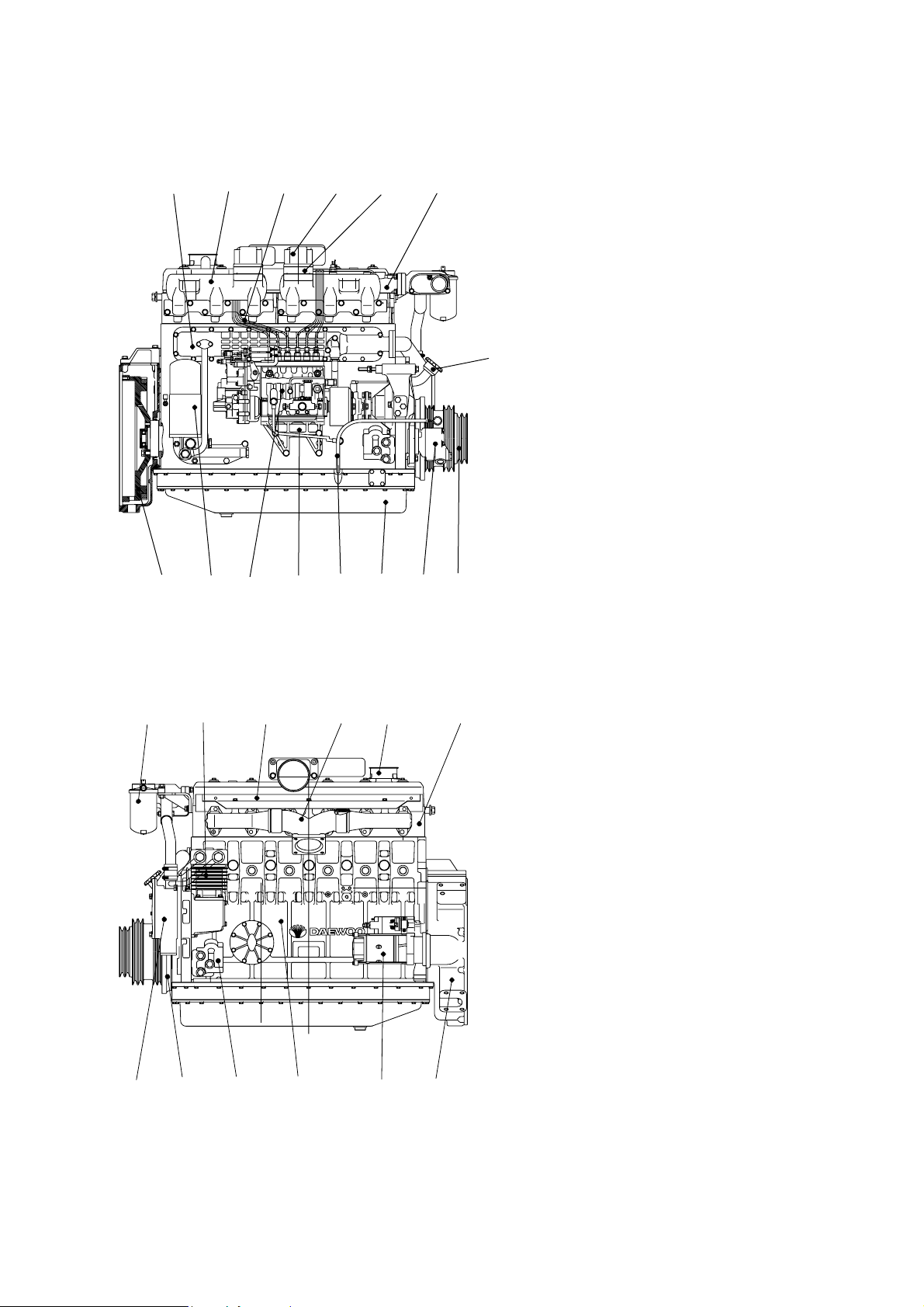
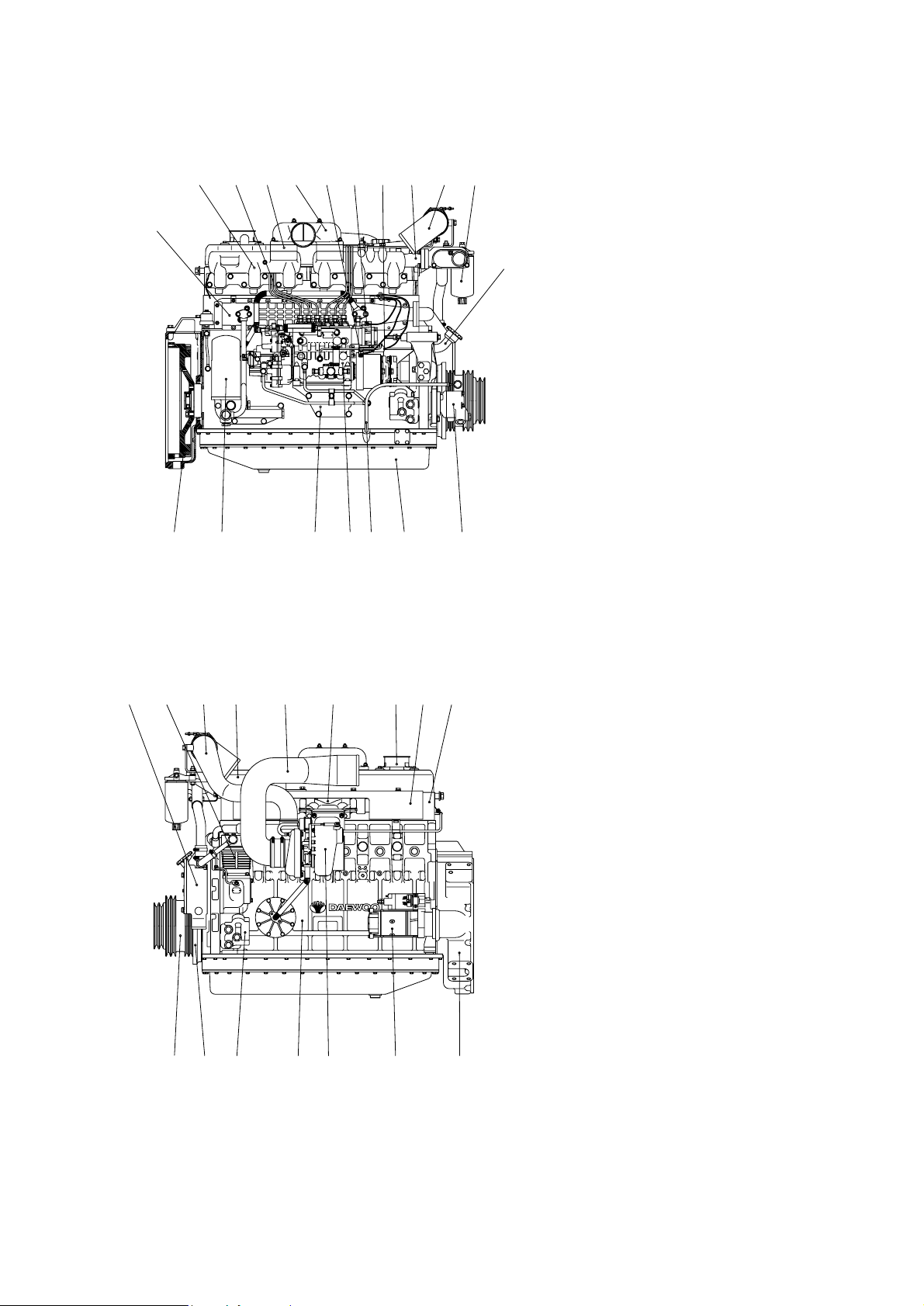
1.5.1. DE12- for Bus
- 13 -
17 19 18 13
4
67920
22
14 5 1 226 23
25 16 15 3 8
21 12 11 27
2410
1. Cylinder block
2. Flywheel housing
3. Breather
4. Oil filler pipe
5. Vibration damper
6. Flywheel
7. V-pulley
8. Cylinder head
9. Oil filter
10. Oil cooler
11. Oil pan
12. Oil dipstick
13. Cooling water pipe
14. Water pump
15. Exhaust manifold
16. Heat shield
17. Intake manifold
18. Intake stake
19. Injection pipe
20. Injection pump
21. Injection pump bracket
22. Fuel filter
23. Starter
24. Air heater
25. Air compressor
26. Mounting bracket
27. Power steering pump
EQM1010I
- 14 -
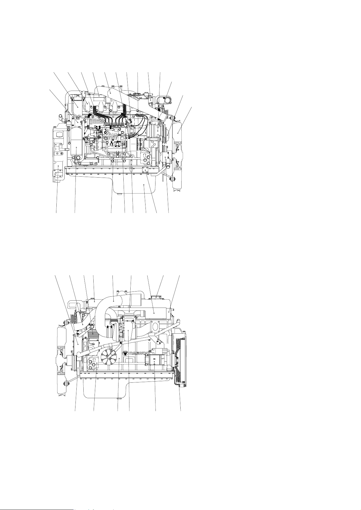
1.5.2. DE12- for Truck
18
24
7
610
15
2251285
EA2M1003
30 17938
22 294121321
16
272319 142620
11
1. Cylinder block
2. Flywheel housing
3. Breather
4. Oil filler pipe
5. Vibration damper
6. Flywheel
7. Idle pulley
8. Cylinder head
9. Cylinder head cover
10. Oil filter
11. Oil cooler
12. Oil pan
13. Oil dipstick
14. Cooling water pipe
15. Water pump
16. Cooling fan
17. Exhaust manifold
18. Intake manifold
19. Intake stake
20. Injection pipe
21. Injection pump
22. Injection pump bracket
23. Fuel filter
24. Alternator
25. Starter
26. Air heater
27. Air-conditioning compressor
28. Engine mounting bracket
29. Power steering pump
30. Air compressor

- 15 -
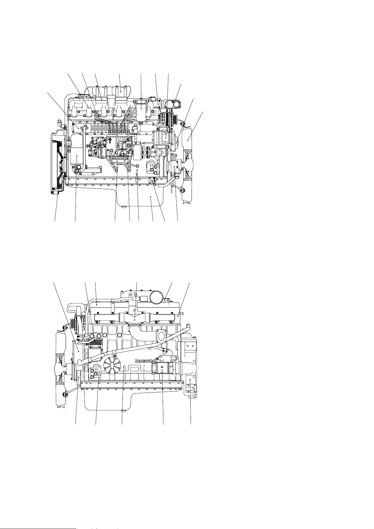
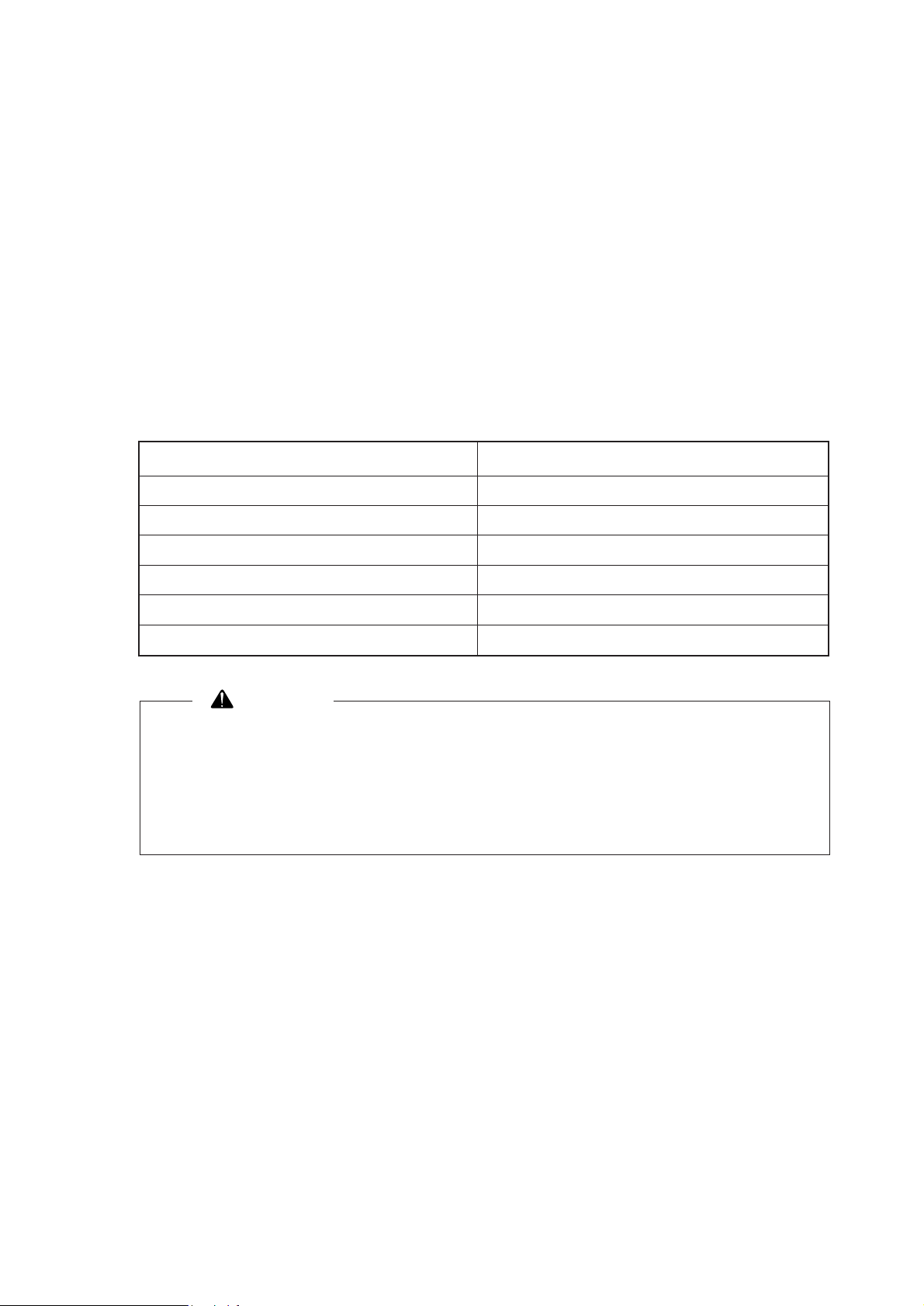
1.5.3. DE12T- for Bus
10 2016 18 13
4
621
23
111222 2897
25
26
17
19
3
15
8
14
5
27
1
24
2
1. Cylinder block
2. Flywheel housing
3. Breather
4. Oil filler pipe
5. Vibration damper
6. Flywheel
7. V-pulley
8. Cylinder head
9. Oil filter
10. Oil cooler
11. Oil pan
12. Oil dipstick
13. Cooling water pipe
14. Water pump
15. Exhaust manifold
16. Intake manifold
17. Heat shield
18. Intake stake
19. Turbocharger
20. Injection pipe
21. Injection pump
22. Injection pump bracket
23. Fuel filter
24. Starter
25. Air heater
26. Air compressor
27. Mounting bracket
28. Power steering pump
EQM1011I

- 16 -
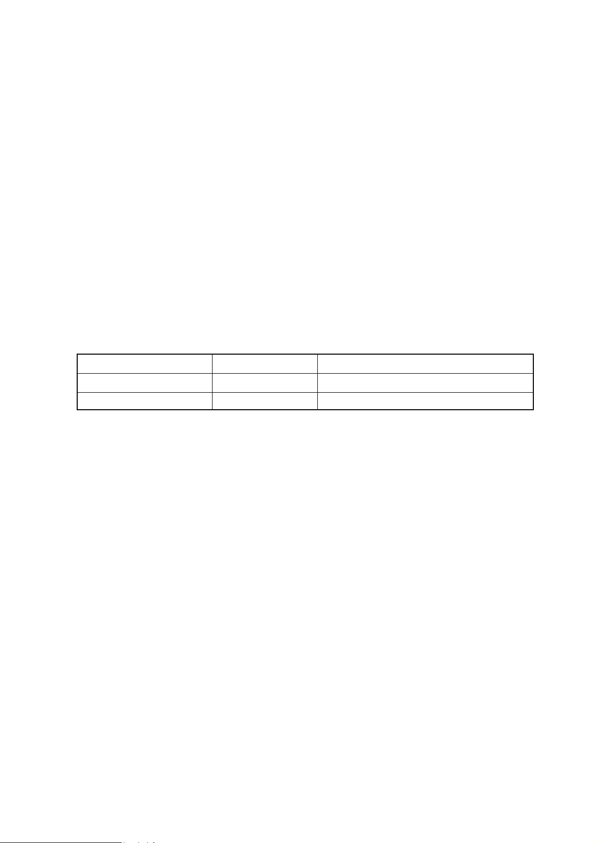
1.5.4. DE12TI(340 ps)- for Bus
10 16 22 17 27 21
29
4
67923
25 28 20 18
14 30 2651 2
19 1538
24 12 3111
13
1. Cylinder block
2. Flywheel housing
3. Breather
4. Oil filler pipe
5. Vibration damper
6. Flywheel
7. V-pulley
8. Cylinder head
9. Oil filter
10. Oil cooler
11. Oil pan
12. Oil dipstick
13. Cooling water pipe
14. Water pump
15. Exhaust manifold
16. Intake manifold
17. Intake stake
18. Turbocharger
19. Air pipe, T/C-A/P
20. Air pipe, A/P-I/C
21. Air pipe, A/P-I/C
22. Injection pipe
23. Injection pump
24. Injection pump bracket
25. Fuel filter
26. Starter
27. Air heater
28. Air compressor
29. Alternator
30. Mounting bracket
28. Power steering pump
EQM1012I
- 17 -
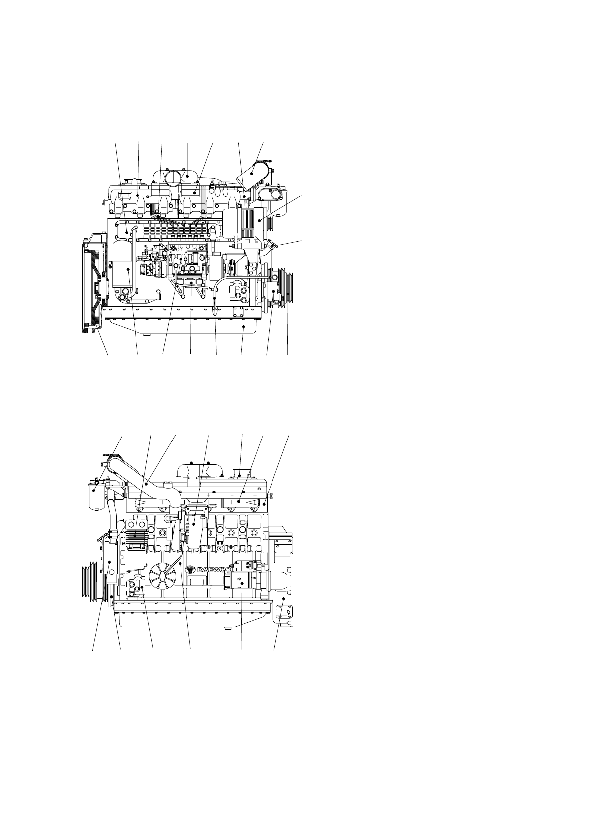
1.5.5. DE12TI(280 ps : ’98 type)- for Bus
10
28
4
9722
24 27 19 18
14 29 2551 2
1538
12 11 30236
17 1321 26 2016
1. Cylinder block
2. Flywheel housing
3. Breather
4. Oil filler pipe
5. Vibration damper
6. Flywheel
7. V-pulley
8. Cylinder head
9. Oil filter
10. Oil cooler
11. Oil pan
12. Oil dipstick
13. Cooling water pipe
14. Water pump
15. Exhaust manifold
16. Intake manifold
17. Intake stake
18. Turbocharger
19. Air pipe, T/C-A/P
20. Air pipe, A/P-I/C
21. Injection pipe
22. Injection pump
23. Injection pump bracket
24. Fuel filter
25. Starter
26. Air heater
27. Air compressor
28. Alternator
29. Mounting bracket
30. Power steering pump
EQM1013I

- 18 -
1.5.6. DE12TI(310 ps : ’98 type)- for Bus
10 16 22 17 27 21
29
4
67923
25 28 20 18
14 30 2651 2
19 1538
24 12 3111
13
1. Cylinder block
2. Flywheel housing
3. Breather
4. Oil filler pipe
5. Vibration damper
6. Flywheel
7. V-pulley
8. Cylinder head
9. Oil filter
10. Oil cooler
11. Oil pan
12. Oil dipstick
13. Cooling water pipe
14. Water pump
15. Exhaust manifold
16. Intake manifold
17. Intake stake
18. Turbocharger
19. Air pipe, T/C-A/P
20. Air pipe, A/P-I/C
21. Air pipe, A/P-I/C
22. Injection pipe
23. Injection pump
24. Injection pump bracket
25. Fuel filter
26. Starter
27. Air heater
28. Air compressor
29. Alternator
30. Mounting bracket
31. Power steering pump
EQM1014I
- 19 -
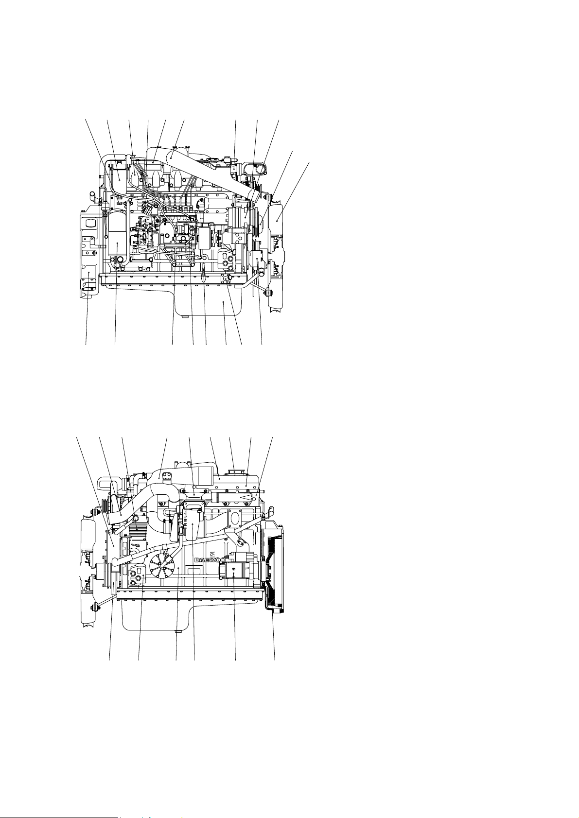
1.5.7. DE12TI - for Truck
EA2M1004
11 14 28 3119 24 30 20
7
16
15 23 34 22 17 1893 8
27
2134
5 32 1 29 621
3312252610
1. Cylinder block
2. Flywheel housing
3. Breather
4. Oil filler pipe
5. Vibration damper
6. Flywheel
7. Idle pulley
8. Cylinder head
9. Cylinder head cover
10. Oil filter
11. Oil cooler
12. Oil pan
13. Oil dipstick
14. Cooling water pipe
15. Water pump
16. Cooling fan
17. Exhaust manifold
18. Heat screen
19. Intake manifold
20. Intake stake
21. Turbocharger
22. Air pipe, A/C-T/C
23. Air pipe, T/C-I/C
24. Injection pipe
25. Injection pump
26. Injection pump bracket
27. Fuel filter
28. Alternator
29. Starter
30. Air heater
31. Air-conditioning compressor
32. Engine mounting bracket
33. Power steering pump
34. Air compressor
- 20 -
1.5.8. DE12TIS - for Bus
EA2M1005
18
11
4
6
15
71 233 31205
1735 22 21 16938
10 2912 12 341325
24 32 19 1426 23 3027 28
1. Cylinder block
2. Flywheel housing
3. Breather
4. Oil filler pipe
5. Vibration damper
6. Flywheel
7. Crank shaft pulley
8. Cylinder head
9. Cylinder head cover
10. Oil filter
11. Oil cooler
12. Oil pan
13. Oil dipstick
14. Cooling water pipe
15. Water pump
16. Exhaust manifold
17. Heat screen
18. Intake manifold
19. Intake stake
20. Turbocharger
21. Air pipe, A/C-T/C
22. Air pipe, T/C-A/P
23. Air pipe, A/P-I/C
24. Injection pipe
25. Injection pump
26. Pick-up sensor
27. Prestroke actuator sensor
28. Rack sensor
29. Injection pump bracket
30. Fuel filter
31. Starter
32. Air heater
33. Engine mounting bracket
34. Power steering pump
35. Air compressor
- 21 -
1.5.9. DE12TIS - for Truck
30
11
31
16
7
20 26 27 28 34332419 14
2410
15
56135 3221
923 37 22 17 18 3 8
29 25 13 12 36
EA2M1006
1. Cylinder block
2. Flywheel housing
3. Breather
4. Oil filler pipe
5. Vibration damper
6. Flywheel
7. Idle pulley
8. Cylinder head
9. Cylinder head cover
10. Oil filter
11. Oil cooler
12. Oil pan
13. Oil dipstick
14. Cooling water pipe
15. Water pump
16. Cooling fan
17. Exhaust manifold
18. Heat screen
19. Intake manifold
20. Intake stake
21. Turbocharger
22. Air pipe, A/C-T/C
23. Air pipe, T/C-I/C
24. Injection pipe
25. Injection pump
26. Pick-up sensor
27. Prestroke actuator sensor
28. Rack sensor
29. Injection pump bracket
30. Fuel filter
31. Alternator
32. Starter
33. Air heater
34. Air-conditioning compressor
35. Engine mounting bracket
36. Power steering pump
37. Air compressor
2. Major maintenance
2.1. Preventive maintenance
2.1.1. Cooling water
1) Check the coolant level of the radiator by removing the radiator filler cap, and add coolant if
necessary.
2) Check the pressure valve opening pressure using a radiator cap tester. Replace the radiator
filler cap assembly if the measured value does not reach the specified limit.
3) When injecting antifreeze solution, first drain out the old coolant from the cylinder block and
radiator, and then clean them with cleaning solution.
4) Be sure to mix soft water with antifreeze solution .
5) A proportion of antifreeze is represented as the ratio of antifreeze in volume, and antifreeze
must be added according to each ambient temperature as described below:
6) When the ratio of antifreeze in the mixture decreases new coolant should be added to make
up for the loss in old coolant resulting from engine operation, check the mix ratio with every
replenishment of coolant, and top up as necessary.
7) To prevent corrosion or air bubbles in the coolant path, be sure to add a specific additive, i.e.
corrosion inhibitor, to the coolant.
• Type : DAC65L
• Mix ratio : 1.5M of inhibitor to 50M of coolant
(Namely, add corrosion inhibitor amounting to 3% of water capacity.)
8) Add antifreeze of at least 5% in volume to prevent possible engine corrosion in hot weather.
If you add antifreeze in excess of 50% in volume, the engine may be overheated.
Avoid this.
As the individual freezing points corresponding to the above proportions of antifreeze
are subject to change slightly according to the kind of antifreeze, you must follow the
specifications provided by the antifreeze manufacturer.
Antifreeze solution(%) Freezing point(C)
20 -10
27 -15
33 -20
40 -25
44 -30
50 -40
- 22 -
CAUTION
2.1.2. Fan belt
1) Use a fan belt of specified dimensions, and replace if damaged, frayed, or deteriorated.
2) Check the fan belt for belt tension. If belt tension is lower than the specified limit, adjust the
tension by relocating the alternator and air conditioner. (Specified deflection: 10~15mm when
pressed down with thumb)
2.1.3. Engine oil
1) Check oil level using the oil dipstick and replenish if necessary.
2) Check the oil level with the vehicle stationary on a level ground, engine cooled. The oil level
must be between MAX and MIN lines on the stick.
3) Engine oil should be changed at the specified intervals. Oil in the oil filter also should be
changed simultaneously.
(First oil change : 1,000km running)
• Suggested engines oils
2.1.4. Oil filter
1) Check for oil pressure and oil leaks, and repair or replace the oil filter if necessary.
2) Change the oil filter element simultaneously at every replacement of engine oil.
2.1.5. Fuel filter
1) Drain water in cartridge with losen the cock under filter from time to time.
2) The fuel filter should be replaced at every 20,000km
2.1.6. Air cleaner
1) Replace any deformed or broken element or cracked air cleaner.
2) Clean or replace the element at regular intervals
Engine Model SAE NO. API NO
DE12, DE12T,DE12TI 15W40 CD grade or above
DE12TIS 15W40 CG grade
- 23 -
2.1.7. Valve clearance
1) Turn the crank shaft so that the piston in No. 1 cylinder reaches the TDC on compression
stroke, then adjust the valve clearance.
2) After releasing the lock nut for the rocker arm adjusting screw, insert a feeler gauge of specified thickness into the clearance between the rocker arm and valve stem, and adjust the
clearance with the adjusting screw. Fully tighten the lock nut when a correct adjustment is
obtained.
3) Carry out the same adjusting operation according to the firing order(1-5-3-6-2-4)
(Valve clearance(with engine cooled): 0.30mm for both intake and exhaust)
2.1.8. Cylinder compression pressure
1) Stop the engine after warming up, then remove the nozzle holder assembly.
2) Install a special tool(gauge adapter) in nozzle holder hole and mount the compression gauge
in position of the nozzle holder.
3) Cut off fuel circulation, rotate the starter, then measure compression pressure in each cylinder.
6 Testing conditions: Coolant temperature 20C, Engine speed, 200 rpm (10 turns)
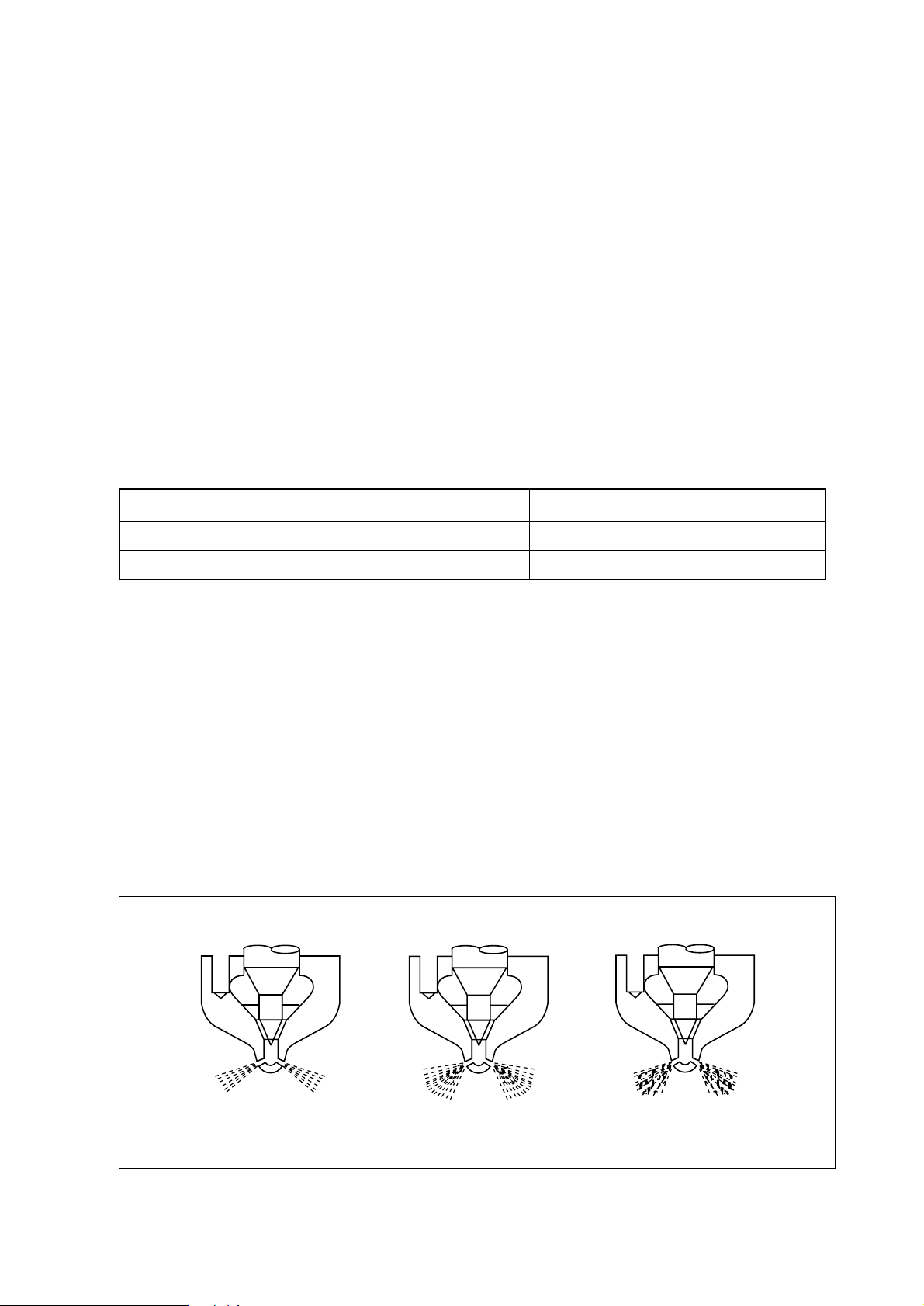
2.1.9. Injection nozzle
1) Assemble a nozzle to a nozzle tester.
2) Check injection pressure, and adjust the nozzle using the adjusting shim if the pressure does
not meet the specified limit.
3) Check nozzle spray patterns and replace if damaged.
Standard 28 kg/cm2over
Limit 24 kg/cm2or less
Difference between each cylinder L10% or less
- 24 -
Normal Abnormal Abnormal
<Figure 2-1> Nozzle spray patterns
EFM1006I

2.1.10. Fuel injection pump
1) Check the fuel injection pump housing for cracks or breaks, and replace if damaged.
2) Check and see if the lead seal for idling control and speed control levers have not been
removed.
2.1.11. Battery
1) Check the battery for damage or leaking of battery fluid(electrolyte) from cracks on the battery. Replace the battery if damaged.
2) Check battery fluid level and add distilled water if necessary.
3) Measure the specific gravity of the electrolyte in the battery. Recharge the battery if the
hydrometer readings are lower than the specified limit(1.12~1.28)
- 25 -
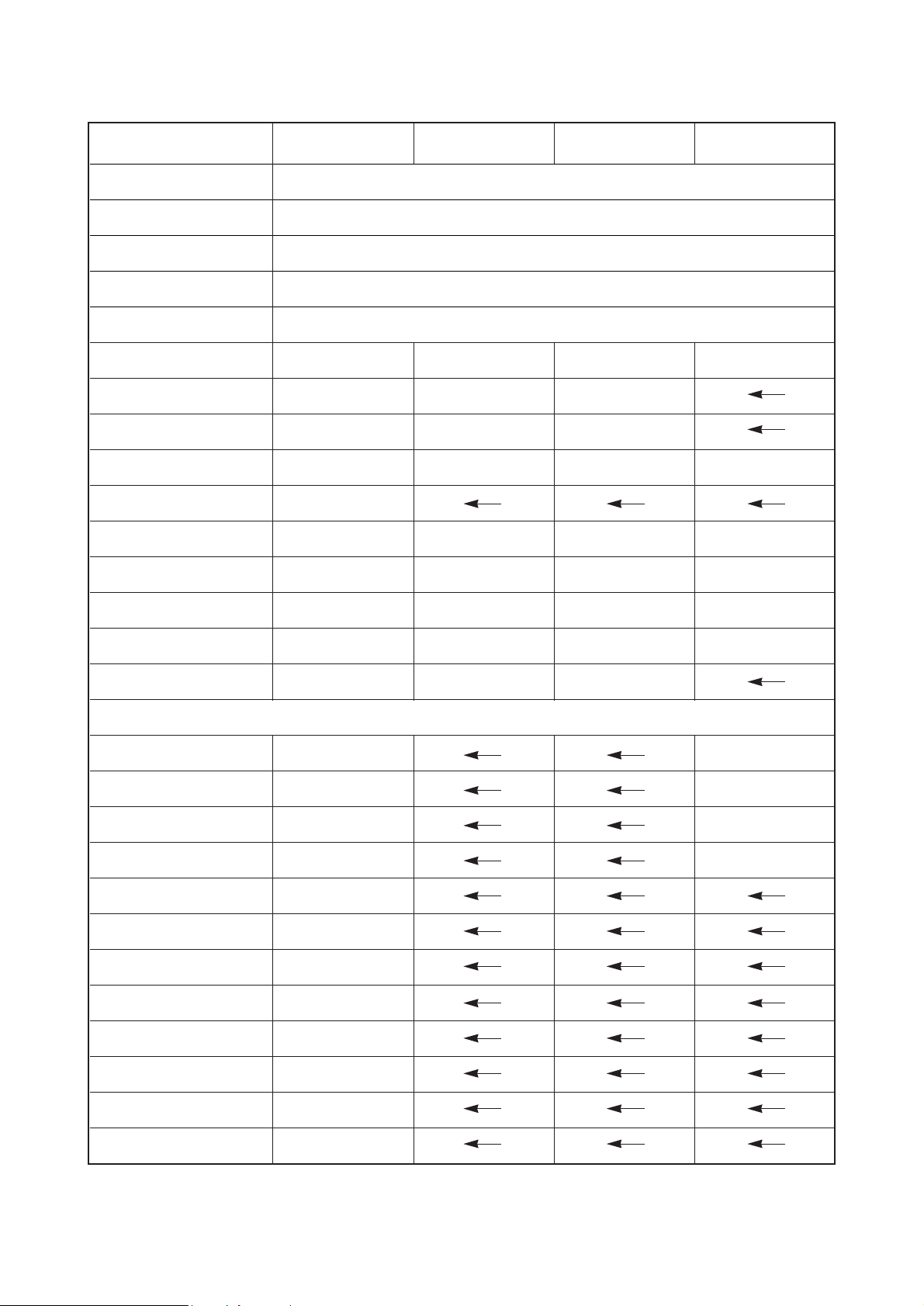
2.2. Diagnostics and trouble shooting for the engine
2.2.1. Diagnostics
- 26 -
1. Engine won’t start
Starter does not turn Starter turns but engine does not start
Check battery fluid and specific gravity Engine Fuel
Too low Check air cleaner Check fuel level
Replenish or recharge
Check cable connections
Check starter s/w
Check starter relay
Check magnetic s/w
Disassemble and check starter motor
Disassemble and check injection pump
Normal
Fouled
Replace or clean element
Check compression pressure
Check other parts
Check cylinder head gasket
Overhaul the engine
(valve assembly, cylinder
liner, piston, etc.)
Check fuel feed pump for function
Check feed pump valve and strainer Air in the fuel
Retighten the joint and/or replace gasket
Air bleeding
Continuous entry of air in fuel system
Disassemble and check feed pump
Dirty element and/or overflow valve faulty
Check fuel filter
Replace
Normal
Too low
Retighten or replace
Check valve clearance
Normal
No fuel
Replenish
Check fuel injection
Normal
AdjustNormal
Repair or replaceNormal
No fuel injection
Air bleeding and re-start
Check injection timing
Check injection nozzle(injection
pressure, injection condition, etc.)
Disassemble and check
injection pump
Normal
AdjustNormal
ReplaceNormal
Clean or replaceNormal
Normal
Replenish or recharge
Normal
Replenish or recharge
Normal
ReplaceNormal
Replenish or recharge
Normal
Overhaul the engine
- 27 -
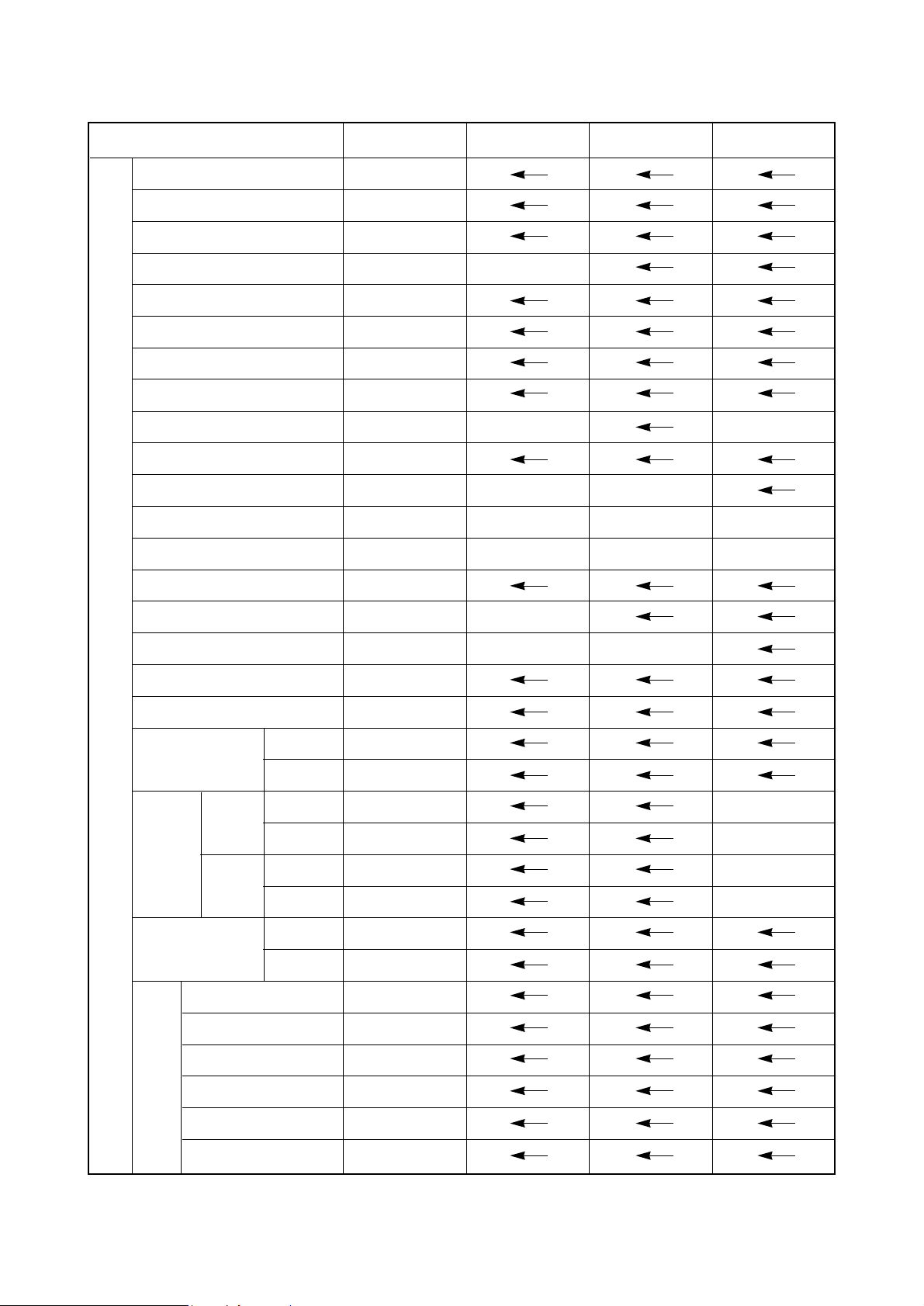
2. Engine overheating
Cooling system Fuel system
Check coolant level Check fuel quality
Operating conditions
1. Overload
2. Clogged radiator core
3. Continued overrunning
Too lowNormal Bad
Repair or replaceNormal
ReplaceNormal
ReplaceNormal
Damaged
Repair or replace
Normal
Check fan belt for tension, wear, or breaks Clean or replace with the specified fuel
Check radiator cap Replenish
Check thermostat
Check radiator
Repair or replaceNormal
Check water pump
Check water pump
InternalExternal
Overhaul engineRetighten or repair
Clean coolant path
Abnormal
Repair or replace
Normal
Check injection nozzles
Excessive fuel rate
Adjust or repair injection pump

- 28 -
3. Lack of power
Engine Chassis
Check for clutch slip
Adjust or replace clutch
Fuel system Others
Check fuel line for air Check air cleaner
Check engine control rod, link and
cable
Check fuel feed pump
Check fuel filter element and overflow valve
Check injection piping
Check injection nozzle(injection pres-
sure, nozzle spray patterns, etc.)
Normal Clean or replace
Normal Clean or replace
Normal
Check valve clearance
Check cylinder head gasket for break
Overhaul engine(valve assembly)
Adjust
Normal Adjust
Normal Replace
Normal Replace
Normal Repair or replace
Normal Adjust or replace
Normal Adjust
Check injection timing
Overhaul engine or injection pump

- 29 -
4. Low oil pressure
Normal
Normal Too high
Normal
Normal Adjust or replace
Check if oil pressure gauge
indicates exactly
Check cooling water temperature
Too low
Refill with recommanded oil
Check oil quality Refer to ‘Engine overheating’
Check oil pressure relief valve Water, fuel, etc. mixed in oil
Overhaul engine or injection pump
Inadequate
Replace with suggested lub. oil
Overhaul the engine
Check oil level

- 30 -
5. High fuel consumption
Normal
Normal Adjust or replace
Normal
Normal
Normal
Normal
Check injection timing
Check compression pressure
Disassemble injection pump
Check head gasket
Overhaul engine
(valve assembly, piston,
cylinder liner, etc.)
Check injection nozzle (injection
pressure, spray patterns, etc.)
Causes according to operating conditions
1. Overload
2. Frequent use of low gear position at high speed
3. Frequent use of high gear position at low speed
4. Clutch slip
5. Too low tire inflation pressure
Oil leakage
Retighten or replace
Check fuel leakage
Adjust
Check valve clearance
Repair or replace
Cylinder liner
Piston ring
Piston
Adjust
Replace

Clean or replace
Oil leak
External Internal
Normal
Disassemble cylinder
head(valve stem seal)
Check compression pressureRetighten or replace
Overhaul engine
(piston, cyl. liner)
- 31 -
6. Excessive oil consumption
Normal
Check oil quality
Replace with suggested lub. oil
Causes according to operating conditions
1. Too high lub. oil level
2. Continuous driving at low speed or
with excessive cold engine
Check oil leakage Check air cleaner

- 32 -
7. Engine knocks(excessive)
Identified
Overhaul engineCheck compression pressure
Check injection timing
Check fuel quality
Use suggested fuel
Normal Too low
Check valve clearance, cyl.
head gasket for damage
Normal Adjust
Normal Replace or adjust
Overhaul engine
Check fuel and oil burning(Check
carbon deposit from exhaust gas)
Not identified

- 33 -
8. Dead or weak battery
Alternator
Check fan belt for
deflection, damage, etc.
Check battery fluid level
Harness, switch
Check wiring connections
for short, etc
Repair or replace
Battery
Normal
Replenish Replace Recharge
Check battery fluid specs.
Damaged battery case
Normal
Check charging condition
Discharged
Disassemble alternator
and regulator
Abnormal
Adjust or replace
Battery discharged Battery overcharged
Check alternator and
voltage regulator

Complaint Cause Correction
- 34 -
1) Difficulty in engine
starting
(1) Trouble in starter
(2) Trouble in fuel system
(3) Lack of compression
pressure
2) Rough engine idling
3) Lack of engine power
(1) Engine continues to
lack power
(2) Engine lacks power on
acceleration
4) Engine overheating
(See <2.2.1>)
(See <Section 4.3 Fuel system>)
Valves holding open, skewed valve stem
Valve springs damaged
Leaky cylinder head gasket
Worn pistons, piston ring, or liner
Wrong injection timing
Air in injection pump
Valve clearance incorrect
Valve poorly seated
Leaky cylinder head gasket
Piston rings worn, sticking, or
damaged
Injection timing incorrect
Volume of fuel delivery insufficient
Nozzle injection pressure incorrect
or nozzles seized
Feed pump faulty
Restrictions in fuel pipes
Volume of intake air insufficient
Compression pressure insufficient
Injection timing incorrect
Volume of fuel delivery insufficient
Injection pump timer faulty
Nozzle injection pressure or spray
angle incorrect
Feed pump faulty
Volume of intake air insufficient
Lack of engine oil or poor oil
Lack of coolant
Fan belts slipping, worn or damaged
Water pump faulty
Thermostat inoperative
Valve clearance incorrect
Back pressure in exhaust line
7
6
5
4
3
2
1
7
6
5
4
3
2
1
10
9
8
7
6
5
4
3
212
1
4
3
2
1
Check valve and valve seat,
then repair or replace
Replace valve springs
Replace gasket
Replace
Adjust
Air bleeding
Adjust
Repair
Replace gasket
Replace piston rings
Adjust
Adjust injection pump
Adjust or replace nozzles
Repair or replace
Repair
Clean or replace air cleaner
Overhaul engine
Adjust
Adjust injection pump
Repair or replace
Repair or replace
Repair or replace
Clean or replace air cleaner
Replenish or replace
Replenish or replace
Adjust or replace
Repair or replace
Replace
Adjust
Clean or replace
2.2.2. Trouble shooting

- 35 -
Complaint Cause Correction
5) Engine noises
(1) Crankshaft
(2) Conn. rod and conn.
rod bearings
(3) Pistons, piston pins,
and piston rings
(4) Others
6) Excessive fuel
consumption
It is important to correctly locate the
causes of noise since generally noises may originate from various engine
components such as rotating parts,
sliding parts, etc.
Oil clearance excessive due to
worn bearings or crankshaft
Crankshaft worn out-of-round
Restrictions in oil ports and resultant lack of oil supply
Bearings seized up
Conn. rod bearings worn out-ofround
Crank pin worn out-of-round
Conn. rod skewed
Bearings seized up
Restrictions in oil ports and resultant lack of oil supply
Piston clearance excessive due to
worn piston and piston rings
Piston or piston pin worn
Piston seized up
Piston poorly seated
Piston rings damaged
Crankshaft and/or thrust bearing
worn
Camshaft end play excessive
Idle gear end play excessive
Timing gear backlash excessive
Valve clearance excessive
Tappets and cams worn
Injection timing incorrect
Volume of fuel injection excessive
Tire under-inflated
Gear selection inadequate(frequent
use of low gears)
4
3
2
1
6
5
4
3
2
1
5
4
3
2
1
5
4
3
2
1
4
3
2
1
Replace bearings and grind
crankshaft
Grind or replace crankshaft
Clean oil path
Replace bearings and grind
crankshaft
Replace bearings
Grind crankshaft
Repair or replace
Replace bearings and grind
crankshaft
Clean oil path
Replace pistons and piston
rings
Replace pistons and piston
rings
Replace pistons
Replace pistons
Replace piston rings
Replace thrust bearings
Replace thrust plate
Replace thrust washers
Adjust or replace
Adjust valve clearance
Replace tappets and camshaft
Adjust
Adjust injection pump
Adjust
Select gears correctly according to load

- 36 -
Complaint Cause Correction
7) High oil consumption
(1) Oil leaking into
combustion chamber
(2) Oil leaking past cylinder
head
(3) Oil leaks
Clearance between cylinder liner
and piston excessive
Piston rings and ring grooves
worn excessively
Piston rings broken, worn, or sticking
Piston rings gaps set incorrectly
Piston skirt portion broken, worn
excessively
Oil return holes in oil control ring
restricted
Oil ring seated incorrectly
Breather piping restricted
Valve stems and valve guide
loose excessively
Valve stem seals worn
Leaky cylinder head gasket
Applicable parts loosened
Applicable packings worn
Oil seals worn
3
2
1
3
2
1
8
7
6
5
4
3
2
1
Replace
Replace pistons and piston
rings
Replace piston rings
Correct
Replace pistons
Replace piston rings
Replace piston rings
Clean or replace
Replace as complete set
Replace seals
Replace gasket
Replace or repair gasket
Replace packings
Replace oil seals

3. Disassembly and reassembly of major components
3.1. Disassembly
3.1.1. General precautions
1) Maintenance operation should be carried out in a bright and clean place.
2) Before disassembly, provide parts racks for storage of various tools and disassembled parts.
3) Arrange the disassembled parts in the disassembly sequence and take care to prevent any
damage to them.
3.1.2. Engine oil
1) Take out the oil dipstick.
2) Remove the drain plug from the oil pan
and drain out the engine oil into a container.
3) Reassemble the drain plug with the oil
pan after draining out the engine oil.
- 37 -
EQM3001I
3.1.3. Cooling water
1) Remove the drain plug from the cylinder
block and drain out the cooling water into
a container.
EQM3002I
3.1.4. Fan belt
1) Remove the fan guide and bracket.
2) Loosen the tension adjusting nuts
installed on the alternator and air-conditioning compressor, and take off the fan
belt.
EQM3003I

3.1.5. Cooling fan
1) Remove the flange fixing bolts, then take
off the flange and cooling fan.
- 38 -
EQM3004I
3.1.6. Oil level gauge guide tube
1) Loosen the flange nut installed on the
ladder frame to remove the guide tube.
EQM3005I
3.1.7. Alternator
1) Loosen the alternator fixing bolts to disassemble the alternator, then remove
the tension adjusting bolt and bracket.
EQM3006I
3.1.8. Air-conditioning compressor
1) Remove the compressor fixing bolts and
disassemble the A/C compressor.
2) Disassemble the A/C compressor tension adjusting bolt and alternator fixing
bracket.
3) Disassemble the A/C compressor fixing
bracket.
EQM3007I

3.1.9. Fuel filter
1) Remove fuel hoses connected to the fuel
injection pump, take off the bracket fixing
bolts, then disassemble the fuel filter.
3.1.10. Breather
1) Loosen the clamp screw to remove the
rubber hose.
- 39 -
EQM3008I
3.1.11. Injection pipe
1) Unscrew the hollow screws to disassemble the fuel return pipe.
2) Remove the nuts installed on the fuel
injection pump and nozzles, then disassemble the injection pipe.
EQM3009I
3.1.12. Air heater
1) Remove the electrical wiring for the air
heater.
2) Disassemble the intake pipes by loosening the nuts installed thereon.
3) Disassemble the air heater and gasket.
EQM3010I
3.1.13. Intake manifold
1) Remove the air hose connected to the
fuel injection pump.
2) Loosen the intake manifold fixing bolts,
then disassemble the intake manifold.
EQM3011I

3.1.14. Turbocharger (for DE12T / DE12TI /
DE12TIS only)
1) Release the clamp screw of the rubber
hose connected to the intake manifold,
and take off the intake pipes both simultaneously.
2) Unscrew the exhaust pipe bracket fixing bolts, release the nuts installed on
the turbocharger, then disassemble the
exhaust pipe.
3) Remove the turbocharger after removing the oil supply pipe and return pipe
and releasing the fixing nuts.
3.1.15. Exhaust manifold
1) Release the exhaust manifold fixing
bolts, disassemble the exhaust manifold, then remove the heat shield and
gasket.
Note : Make sure to release the nuts one
after another because the exhaust
manifold will be removed if you
unscrew the two nuts simultaneously.
3.1.16. Starter
1) Unscrew the starter fixing bolts, then
disassemble the starter.
- 40 -
EQM3012S
EQM3013S
EQM3014I
EQM3015I
3.1.17. Thermostat
1) Remove the by-pass pipe connected to
the water pump, unscrew the thermostat fixing bolts, then dissemble the
thermostat assembly.
2) Disassemble the thermostat housing
and remove the thermostat.
3) Disassemble the water pipe by
unscrewing the bolts and nuts installed
on the cylinder head.

3.1.18. Fuel injection pump
1) Remove the oil supply pipe and return
pipe connected to the fuel injection
pump.
2) Unscrew the bolts connecting the coupling and drive shaft, loosen the injection pump attaching bolts, then disassemble the injection pump.
Note : Place the No.1 cylinder in the
exact 'OT' position to disassemble the injection pump.
3) Release the pump fixing bracket bolts
to disassemble the bracket from the
cylinder block.
Note : Do not interchange the shims as
they must be installed in their
original positions at reassembly.
3.1.19. Oil filter
1) Using a filter remover, remove the filter
element.
2) Remove the pipe connected to the oil
cooler.
3) Loosen the oil filter fixing bolts and disassemble the oil filter head from the
cylinder block.
3.1.20. Idle pulley
1) Remove the bolts and disassemble the
idle pulley.
- 41 -
EQM3017I
EQM3016I
EQM3018S
EQM3019S

3.1.21. Power steering pump
1) Remove the oil hoses.
2) Unscrew the hex bolts and remove the
steering pump.
- 42 -
EQM3020S
3.1.22. Water pump
1) Remove the water pipe connected to
the expansion tank
2) Remove the water pipe and hoses connected to the water pump.
3) Unscrew the water pump fixing bolts
and remove the water pump.
EQM3021S
3.1.23. Air compressor
1) Remove the oil hose, water pipe, air
pipe connected to the air compressor,
remove the air cooler fixing bolts, then
disassemble the air compressor from
the timing gear case.
EQM3022S
3.1.24. Vibration damper
1) Unscrew the pulley fixing bolts and disassemble the pulley-vibration damper
assembly.
2) Unscrew the vibration damper fixing
bolts and disassemble the damper from
the pulley.
EQM3023S

3.1.25. Timing gear case cover
1) Disassemble the oil seal using an oil
seal removing jig.
2) Remove the cover fixing bolts and disassemble the cover from the timing
gear case.
- 43 -
EQM3024I
3.1.26. Idle gear
1) Unscrew the idle gear fixing bolts and
disassemble the thrust washer and idle
gear.
2) Disassemble the idle gear pin using a
rubber hammer to prevent damage to
them.
EQM3025S
3.1.27. Fuel injection pump drive assembly
1) Remove the dowel pin for the steering
pump.
2) Unscrew the injection pump drive shaft
bearing housing fixing bolts and remove
the injection pump drive assembly in
which the shaft, gear, bearings, and
housing are put together.
EQM3026I
3.1.28. Cylinder head cover
1) Unscrew the cover fixing bolts and disassemble the cover.
2) Keep the bolts in an assembly state so
that the packings and washers may not
be lost, and keep the cover packing as
assembled with the cover.
EQM3027I

3.1.29. Rocker arm assembly
1) Unscrew the rocker arm bracket bolts
and remove the rocker arm assembly.
2) Take off the snap rings to remove the
washers and rocker arm, then unscrew
the bracket fixing bolts to take off the
bracket and springs.
3) Take out the push rods.
- 44 -
EQM3028I
3.1.30. Injection nozzle
1) Remove the nozzle fixing nuts and
extract the nozzles.
2) Remove the nozzle tube using nozzle
tube removing jig.
Do not perform disassembly operation unless coolant, gas, etc. leak
out.
EQM3029I
3.1.31. Cylinder head
1) Unscrew the cylinder head fixing bolts
and take off the cylinder head.
2) Remove the cylinder head gasket.
EQM3030I
3.1.32. Valve and valve stem seal
1) Compress the valve spring retainer using
a jig and take off the valve cotter pin.
2) Disassemble the valve springs and
retainer.
3) Take off the valve.
4) Remove and discard the valve stem
seal using a general tool as it should
not be re-used.
EJM3027S
Compress the spring

3.1.33. Oil cooler
1) Remove the water pipe connected to
the water pump.
2) Unscrew the oil cooler cover fixing bolts
and disassemble the oil cooler assembly from the cylinder block.
3) Unscrew the oil cooler fixing bolts and
remove the oil cooler from the oil cooler
cover.
3.1.34. Oil pan
1) Stand the engine with the flywheel
housing facing toward the bottom.
2) Release the oil pan fixing bolts, remove
the stiffeners, then disassemble the oil
pan.
- 45 -
EQM3031I
EQM3032I
3.1.35. Oil pump and oil pipe
1) Unscrew the oil inlet pipe bracket bolts,
releasing the pipe fixing bolts, then disassemble the oil suction pipe assembly.
2) Disassemble the oil pipe feeding oil
from the oil pump to the cylinder block.
3) Unscrew the oil pump fixing bolts and
disassemble the oil pump.
EQM3033I
3.1.36. Ladder frame
1) Disassemble the ladder frame.
EQM3034I

3.1.37. Piston and connection rod
1) Disassemble the pistons by two hands
while turning the crankshaft.
2) Unscrew the conn. rod fixing bolts and
take off the pistons and conn. rods in
the direction of piston.
- 46 -
EQM3035I
3) Remove the piston pin snap rings, take
off the piston pin, then disconnect the
conn. rod from the piston.
EQM3036S
4) Disassemble the piston rings using ring
pliers.
5) Take care not to interchange the disassembled parts and keep them in the
sequence of cylinder No.
EQM3037S
3.1.38. Cylinder liner
1) Take off the cylinder liner.
EQM3038I
Piston ring jig

3.1.39. Flywheel
1) Position the engine so that the head
installing surface of the cylinder block
faces down.
2) Unscrew the flywheel fixing bolts and fit
a dowel pin.
3) Install flywheel disassembling bolts in
the bolt holes machined on the flywheel,
and disassemble the flywheel.
3.1.40. Oil seal
1) Take off the rear oil seal using an oil
seal disassembling jig.
2) If only the inside guide ring is removed,
use a general tool to take off the outside
seal.
- 47 -
EQM3039I
EQM3040I
3.1.41. Flywheel housing
1) Loosen the housing fixing bolts and disassemble the flywheel housing.
EQM3041I
3.1.42. Cam shaft and tappet
1) Remove the cam shaft gear.
2) Take off the cam shaft gear thrust
washer.
3) Take out the cam shaft carefully not to
damage the cam shaft.
4) Slide out the tappets by hand.
EQM3042I

3.1.43. Crankshaft gear and oil pump idle
gear
1) Loosen the socket head bolts and take
out the oil pump idle gear.
2) Use a puller to remove the crankshaft
gear.
- 48 -
EQM3043S
3.1.44. Timing gear case
1) Unscrew the case fixing bolts and disassemble the timing gear case.
EQM3044I
3.1.45. Crankshaft
1) Unscrew the main bearing cap fixing
bolts and remove the bearing cap.
2) Take off the crankshaft.
3) Take off the main bearing.
EQM3045S
3.1.46. Oil spray nozzle
1) Remove the oil spray nozzles.
EQM3046S
Puller

3.2. Inspection
3.2.1. Cylinder block
1) Clean the cylinder block thoroughly and make a visual inspection for cracks or damage.
2) Replace if cracked or severely damaged, and correct if slightly damaged.
3) Check oil and water flow lines for restriction or corrosion.
4) Make a hydraulic test to check for any cracks or air leaks.
(Hydraulic test) :
Stop up each outlet port of water/oil passages in the cylinder block, apply air pressure of
about 4kg/cm
2
against the inlet ports, then immerse the cylinder block in water for about 1
minute to check any leaks. (Water temperature: 70
C)
3.2.2. Cylinder head
1) Check the cylinder head for cracks or damage.
(1) Carefully remove carbon from the lower face of the cylinder head using nonmetallic mate-
rial to prevent scratching of the valve seat faces.
(2) Check the entire cylinder head for very fine cracks or damage invisible to ordinary sight
using a hydraulic tester or a magnetic flaw detector.
2) Check the lower face of the cylinder
head for distortion.
(1) Measure the amount of distortion
using a straight edge and a feeler
gauge at six positions as shown in
the figure right.
(2) If the measured value exceeds the
standard value(0.2mm), reface the
head with grinding paper of fine grain
size to correct such defect.
(3) If the measured value exceeds the
maximum allowable limit(0.3mm),
replace the cylinder head.
3) Measure flatness of the intake/exhaust
manifolds fitting surfaces on the cylinder
head using a straight edge and a feeler
gauge.
4) Hydraulic test method for the cylinder
head is the same as that for cylinder
block.
- 49 -
EF
A
B
C D
EQM3047I
<Figure 3-1> Measuring cylinder head
distortion

3.2.3. Valve and valve guide
1) Inspecting the valve
Clean the valves with clean diesel oil,
then inspect them as follows:
(1) Measure the valve stem outer diam-
eter at 3 positions(top, middle, and
bottom). If the amount of wear is
beyond the limit(0.18mm), replace
the valve.
(2) Check the valve seat contacting
faces for scratches or wear, and correct the faces with grinding paper as
necessary. Replace if severely damaged.
(3) Measure the valve head thickness,
and replace the valve if the measured value is 1mm or less(a).
Dimensions
Standard Limit
Descriptions
Intake valve
N10.950~10.970 10.87
stem (mm)
Exhaust valve
N10.935~10.955 10.84
stem (mm)
2) Inspection and measurement of valve guide
(1) Install the valve into the valve guide and measure the clearance between them by valve
movement. If the clearance is excessive, measure the valve and replace either the valve or
the valve guide, whichever worn more.
(2) Install the valve into the cylinder head valve guide, then check and see if it is centered with
the valve seat using a special tool.
- 50 -
END OF STEM
EFM2036I
<Figure 3-2> Measuring valve stem
EQM3048I
<Fig. 3-3> Measuring thickness of valve head
a

3) Inspection and correction of valve seat
(1) Measure the contacting face
between the intake valve seat and
exhaust valve seat for valve seat
wear, and replace if the measured
value exceeds the specified limit.
(2) Install the valve into the valve seat on
the cylinder head, and check the
amount of depression of the valve
from the lower portion of the cylinder
head using a dial gauge.
If the amount of depression is beyond the specified limit, replace the valve seat.
(3) For removal of the valve seat, apply arc welding work to two points of valve seat insert,
and pull out valve seat insert with inner extractor.
(4) Undercool a new valve seat with dry ice for about 2 hours and press the valve seat insert
into position in the cylinder head using a special tool(bench press).
(5) Apply valve lapping compound to the valve head seating face on the valve seat and lap
the valve seat by turning it until it is seated in position, then wipe out the lapping compound.
- 51 -
EQM3049I
4) Inspection and correction of valve spring
(1) Visually check the exterior of the
valve springs for damage, and
replace if necessary.
(2) Measure free length and spring ten-
sion with a valve spring tester.
(3) Measure the spring inclination with a
square.
(4) Compare the measured value with
the standard value to determine
whether to replace or repair.
1mm or less
Free length
Square
EFM2039I
<Figure 3-4> Measuring spring tension and
inclination
-0.3~0

3.2.4. Rocker arm shaft assembly
1) Measurement of rocker arm shaft
(1) Place the rocker arm shaft on two V-
blocks and inspect the shaft for bend
using a dial gauge.
If the amount of this run-out is small,
press the shaft with a bench press to
correct the run-out. Replace the
shaft if the measured value exceeds
the limit.
(2) With an outside micrometer, measure the rocker arm shaft diameter at the point where
the rocker arms have been installed. Replace the rocker arm if the amount of wear is
beyond the specified limit.
2) Inspection of rocker arm
(1) Visually check the face of the rocker arm in contact with the valve stem end for scores
and step wear. If the wear is small, correct it with an oil stone or grinding paper of fine
grain size. Rocker arm with a considerable amount of step wear should be replaced.
(2) Measure the inside diameter of the rocker arm bushing with an inside micrometer or
vernier calipers, and compare the measured values with the rocker arm shaft diameter. If
the clearance exceeds the limit, replace either bushing or shaft, whichever worn more.
- 52 -
EDM2037I
<Figure 3-5> Measuring run-out of rocker arm
shaft
3) Inspection of tappet and push rod
(1) Measure the outer diameter of the
tappets with an outside micrometer.
If the amount of wear is beyond the
specified limit, replace tappets.
(2) Visually check the face of the tappets
in contact with the cam for pitting,
scores or cracks, and replace if
severely damaged. If the amount of
cracks or pitting is small, correct with
an oil stone or grinding paper.
(1) Pitting (2) Crack (3) Normal
(4) Abnormal
EFM2041I
<Figure 3-6> Inspecting tappet face
(3) Support the push rod on two V-
blocks and check for bend using a
feeler gauge.
EDM2037I
<Figure 3-7> Measuring push rod run-out

3.2.5. Cam shaft
1) Inspection of cam
(1) Measure the cam height with a
micrometer and replace the camshaft
if the measured value is beyond the
specified limit.
(2) Inspect the cam face for scratch or
damage.
Slight step wear or damage on the
cam face may be corrected with oil
stone or oiled grinding paper. But,
replace if severely damaged.
- 53 -
EDM2045I
<Figure 3-8> Measuring cam height
2) Inspection of cam shaft
(1) With an outside micrometer, mea-
sure the camshaft journal diameter.
(2) Measure the inside diameter of the
camshaft bushing on the cylinder
block using a cylinder bore indicator,
and compare the measured value
with the camshaft outside diameter to
determine the clearance.
(3) Replace the bushing if the measured
value is beyond the specified limit.
(4) Support the cam shaft on two V-
blocks and check for run-out using a
dial indicator. Correct or replace the
cam shaft if the amount of run-out is
beyond the value indicating need for
servicing.
EAOM4063
<Figure 3-9> Measuring inside diameter of
cam shaft bushing on cylinder block
EFM2046I
<Figure 3-10> Measuring cam shaft run-out
3) Cam shaft end play
(1) Push the thrust plate toward the cam
gear.
(2) With a feeler gauge, measure the
clearance between the thrust plate
and cam shaft journal.
(3) If the end play is excessive, replace
the thrust plate.
EAOM4067
<Figure 3-11> Measuring cam shaft axial play
Cam bushing

3.2.6. Crank shaft
1) Inspection for scores or cracks
(1) Visually check the crank shaft journal and crank pins for scores or cracks.
(2) Using a magnetic power and color check, inspect the crank shaft for cracks, and replace
the crank shaft which has cracks.
2) Checking crank shaft for wear
(1) With an outside micrometer, measure the diameter of the crank shaft journals and pins in
the directions as shown, and compare the measured values to determine the amount of
wear.
(2) If the amount of wear is beyond the limit, have the crank shaft ground and install under-
size bearings. However, if the amount of wear is within the limit, you can correct the wear
using an oil stone or oiled grinding paper of fine grain size.
(Be sure to use grinding paper which has been immersed in oil.)
•Undersize bearings available
(1) Standard
(2) 0.25 (Inside diameter is 0.25mm
lesser than the standard size.)
(3) 0.50 (Inside diameter is 0.50mm
lesser than the standard size.)
(4) 0.75 (Inside diameter is 0.75mm
lesser than the standard size.)
(5) 1.00 (Inside diameter is 1.00mm
lesser than the standard size.)
Undersize bearings are available in
4 different sizes as indicated above,
and the crankshaft can be reground
to the above sizes.
- 54 -
B B
B
A
A
B
EFM2047I
<Figure 3-12> Measuring crank shaft outer
diameter
Note : When regrinding the crank
shaft as described above, the
fillet section 'R' should be finished correctly.
Avoid sharp corners or insufficient fillet.
Standard values of 'R'
Crankshaft pin 'R' : 4.5
Crankshaft journal 'R' : 4
" R "
" R "
" R "
Right Wrong Wrong
" R " " R "
EFM2048I
<Figure 3-13> The shape of crankshaft 'R'
1
2
“R”

3) Measurement of crankshaft run-out
(1) Support the crankshaft on V-blocks.
(2) Turn the crankshaft with a dial indi-
cator placed on the surface plate and
take the amount of crank shaft runout.
- 55 -
EDM2040S
<Figure 3-14> Measuring crank shaft run-out
EDM2041S
<Figure 3-15> Measuring crank shaft outer
diameter
3.2.7. Crank shaft bearing and connecting
rod bearing
1) Visually check the crank shaft bearing
and connecting rod bearing for scores,
uneven wear or damage.
2) Check oil clearance between crankshaft
and bearing.
(1) Install the main bearing in the cylin-
der block, tighten the bearing cap to
specified torque, then measure the
inside diameter.
(2) Install the connecting rod bearing in
the conn. rod bearing cap, tighten the
connecting rod cap bolts to specified
torque, then measure the inside
diameter.
EDM2042S
EQM3050S
<Figure 3-16> Measuring main bearing inside
diameter

(3) Compare the two values obtained
through measurement of bearing
inside diameter with the outside
diameters of crankshaft journals and
pins to determine the oil clearance.
(4) If the clearance deviates from the
specified range, have the crankshaft
journals and pins ground and install
undersize bearings.
- 56 -
EDM2044I
<Figure 3-17> Measuring conn. rod bearing
inside diameter
3) Inspection of bearing spread and crush
(1) Check to see that the bearing
requires a considerable amount of
finger pressure at reassembly operation.
(2) With a bearing crush aligner, mea-
sure bearing crush.
•Standard bearing crush
Crank shaft bearing crush(mm)
0.15~0.25
Conn. rod bearing crush(mm)
0.3~0.5
EDM2046S
<Figure 3-18> Checking bearing tension
<Figure 3-19> Bearing and cylinder block
O A
Spread = O A - O B
O B
EDM2047I
EDM2048I
<Figure 3-20> Measuring main bearing crush

(3) Conn. rod bearing crush can be
checked as follows:
Install the bearing and cap in the
conn. rod big end, retighten the bolts
to specified torque, unscrew out one
bolt completely, then measure the
clearance between the bearing cap
and conn. rod big end using a feeler
gauge.
- 57 -
EDM2049I
<Figure 3-21> Conn. rod bearing crush
4) Measurement of crank shaft end play
(1) Assemble the crankshaft to the cylin-
der block.
(2) With a dial gauge, measure crank
shaft end play.
EPM2018S
<Figure 3-22> Measuring crankshaft end play
3.2.8. Piston
1) Visually check the pistons for cracks,
scuff or wear, paying particular attention
to the ring groove.
2) Measurement of the clearance between
the piston and cylinder liner.
(1) With an outside micrometer, mea-
sure the piston outside diameter at a
point 18mm away from the lower end
of piston skirt in a direction at a right
angle to the piston pin hole.
EQM3051S
<Figure 3-23> Measuring piston outside
diameter
<Figure 3-24> Measuring cylinder liner inside
diameter
(2) Using a cylinder bore gauge, mea-
sure cylinder liner inside diameter at
3 points (cylinder top ring contacting
face, middle, and oil ring contacting
face on BDC) in a direction at an
angle of 45°. Take the mean value
with the largest and smallest values
excepted.
2
EQM3052I
Position of measuring
outside diameter

(3) The clearance is computed by sub-
tracting the piston outside diameter
from the cylinder liner inside diameter. Replace either piston or cylinder
liner, whichever damaged more, if
the clearance is beyond the specified
limit.
3.2.9. Piston rings
1) Replace the piston rings with new ones if
detected worn or broken when the
engine is overhauled.
2) Measure piston ring gap.
(1) Insert the piston ring into the upper
portion of the cylinder liner bore so
that it is held at a right angle to the
cylinder liner wall.
(2) Measure the piston ring gap with a
feeler gauge.
(3) Replace piston rings with new ones if
the gap is beyond the limit.
3) Measure piston ring side clearance.
(1) Fit the compression ring and oil ring
in the piston ring groove.
(2) With a feeler gauge, measure side
clearance of each ring, and replace
either the ring or piston if the measured value is beyond the specified
limit.
Dimensions
Standard(mm) Limit(mm)
Descriptions
Top ring 0.40~0.65 1.5
2nd ring 0.40~0.65 1.5
Oil ring 0.30~0.60 1.5
Liner Standard Limit
Cylinder line
inside diameter l123
+0.005
123.225
(mm)
-0.015
- 58 -
EFM2053I
<Figure 3-25> Measuring piston ring gap

4) With a tension tester, measure piston
ring tension. Replace the piston ring if
the measured value is beyond the limit.
3.2.10. Piston pin
1) Measure the amount of wear on the piston pin
(1) Measure the amount of wear on the
piston pin at the points as shown.
The measured values are beyond
the limit(0.005mm or greater),
replace the pin.
(2) Measure the clearance between the
piston pin and conn. rod bushing,
and replace either of them, which
ever damaged more, if the measured value is beyond the
limit(0.011mm).
2) Check the engaged condition of the piston and piston pin. If it is possible to
force the pin into the piston heated with
piston heater, the piston is normal.
When replacing the piston, be sure to
replace the piston pin together.
Dimensions
Standard(mm) Limit(mm)
Descriptions
Top ring 2nd ring 0.07~0.102 0.15
Oil ring 0.05~0.085 0.15
- 59 -
B
A (A) (B) (C)
EDM2058I
<Figure 3-26> Measuring piston pin

3.2.11. Connecting rod
1) Check the connecting rod for distortion.
As shown in the figure right, install the
conn. rod to the conn. rod tester, and
check for distortion using a feeler
gauge. If the conn. rod is found distorted, never re-use it and replace it with a
new one.
2) Measure the alignment of the conn. rod
piston ring bushing holes with conn. rod
big end holes. At this time also, use
both conn. rod tester and feeler gauge.
3) Inspection of the amount of wear on the
conn. rod big end and small end
(1) Assemble the conn. rod to the crank
shaft and measure conn. rod big
end side clearance using a feeler
gauge.
(2) Assemble the conn. rod to the piston
and measure conn. rod small end
side clearance.
(3) If the measured values are beyond
the limit(0.5mm), replace the connecting rod.
- 60 -
EJM2087I
<Figure 3-27> Measuring alignment of
conn. rod
3.2.12. Tappet
1) Check the tappets for cracks, scores, or
damage.
2) With an outside micrometer, measure
the tappet outside diameter. If the measured value is beyond the limit, replace
tappets.
EDM2061I
<Figure 3-28> Measuring tappet outside
diameter

3.3.3. Oil spray nozzle
1) Tighten and assemble the oil spray nozzle flange with fixing bolts.
- 61 -
EQM3053I
3.3.4. Tappet and cam shaft
1) Undercool a new bush with dry ice for
about 2 hours and press it into position in
the cylinder block using a bench press.
After the pressing operation, measure
the inside diameter of the cam bush to
check if it is not deformed.
2) Apply engine oil to the entire face of the
tappets and slide them into the tappet
holes on the cylinder block.
EDM2059S
3.3. Reassembly
3.3.1. General precautions
1) Wash clean all the disassembled parts, particularly oil and water ports, using compressed air,
then check that they are free from restrictions.
2) Arrange the general and special tools for engine assembly operation.
3) To wet each sliding part, prepare clean engine oil.
4) Prepare service materials such as sealant, etc.
5) Discard used gaskets, seal rings, and consumable parts, and replace with new ones.
6) Apply only the specified torque for bolts in the specified tightening order and avoid over-tightening.
7) Be sure to check that all the engine parts operate smoothly after being reassembled.
8) Check the bolts for looseness after preliminary reassembly.
9) After completing the engine reassembly operation, check if there is missing parts or shortage
of parts.
10) Keep your hands clean during the working
3.3.2. Cylinder block
1) Cover the floor of the workshop with wood plate or thick paper to prevent damage to the
cylinder head, and place the cylinder block with the head fitting surface facing downward.

3) Wet the cam bush inside diameter and
cam shaft with oil, and carefully assemble them while turning the cam shaft.
4) Check to see that the cam shaft rotates
smoothly.
- 62 -
EDM2060I
3.3.5. Crank shaft
1) Install the main bearing machined with
two holes in the cylinder block so that the
key is aligned with the key groove, then
apply oil to the bearing surface.
2) Apply sealant in the inside wall of the
crank shaft gear evenly before placing
over the shaft
3) Semi-tighten a bolt at both sides of the
crank shaft, apply engine oil to journals
and pins, then assemble the crank shaft
with the cylinder block by tightening the
fixing bolts.
4) Install the oiled thrust washers with the
oil groove facing outward.
EQM3054S
EQM3055S
EQM3056S
Oil port and passage
Key groove

5) Install the bearing and thrust washers to
the bearing cap and apply oil to the bearing and thrust washers.
- 63 -
EQM3057I
6) Install the bearing cap by matching the
cylinder block No. with the bearing cap
No.
7) Apply oil to the entire part of the bearing
cap bolts, then tighten in tightening
sequence to specified torque(30kg
•
m).
8) After semi-tightening both bolts evenly,
tighten them diagonally to about 15kg
•
m
for the first stage and 25kg
•
m for the
second stage respectively, then tighten
them completely to the specified torque
using a torque wrench.
9) Tighten the bearing cap in the sequence
of 4-3-5-2-6-1-7.
10) Check to see that the assembled crank
shaft turns smoothly.
3
4
5
6
7
2
1
EQM3058I
EQM3059I
3.3.6. Flywheel housing
1) Temporarily install the guide bar on the
cylinder block.
2) Apply gasket to the cylinder block.
3) Using the dowel pin and guide bar,
install the flywheel housing and tighten
the fixing bolts in a diagonal sequence to
specified torque(12kg°m)
EQM3060I

3.3.7. Rear oil seal
1) Apply lubricating oil to the outside of the
oil seal and flywheel inside diameter and
fit them over the crank shaft, then
assemble the oil seal using an oil seal fitting jig.
- 64 -
EQM3061I
3.3.8. Flywheel
1) Install a guide bar into a bolt hole on the
crank shaft, and lift the flywheel to align
the dowel pin with the pin hole on the flywheel for temporary assembly operation.
2) Install bolts in the remaining holes with
no guide bar installed, take out the guide
bar, then install a bolt in the hole where
the guide bar had been inserted.
3) Tighten the fixing bolts using a torque
wrench in a diagonal sequence to specified torque(18kg•m).
EQM3062I
2
6
4 8
1
5
7
3
EQM3063I
3.3.9. Timing gear case
1) Mount gasket using dowel pin.
2) Install the timing gear case by aligning
the dowel pin with the dowel pin hole on
the timing gear case.
EQM3064I
<Tightening sequence for flywheel fixing bolts>

3.3.10. Fuel injection pump drive gear
assembly
1) Mount gasket by aligning the bolt holes
with the pin holes on the bearing housing.
2) Tighten up the fixing bolts in the direction
of fuel injection pump.
- 65 -
EQM3065I
3.3.11. Timing gear
1) Install the oil pump idle gear onto the
No. 7 bearing cap.
2) Install a thrust washer over the cam
shaft and assemble the cam gear by
aligning it with cam shaft key groove.
3) With the oil port on the idle gear pin facing the cylinder head, install the idle
gear pin.
4) Install the idle gear by coinciding the
marks impressioned on the crank gear,
cam gear, fuel injection pump drive
gear, and idle gear.
5) Install a thrust washer on the idle gear
and tighten to specified torque (6.2kg
•
m).
6) Check and adjust the amount of backlash between gears using a feeler
gauge. (backlash : 0.1~0.2)
EQM3066I
Fuel injection
pump drive
gear
Idle gear
Cam gear
Crank
gear
EDM2075I
3.3.12. Timing gear case cover
1) Install dowel pin on the timing gear case.
2) Mount a gasket by aligning the fixing
bolt holes with those on the gasket.
3) Align the dowel pin with the cover pin
hole, then install the cover with a light tap.
4) Tighten the fixing bolts beginning with
the oil pan fitting face.
EQM3067S
<Timing gear marks>

3.3.13. Front oil seal
1) Apply lubricating oil to the outside of the
oil seal and timing gear case inside
diameter and fit them over the crank
shaft, then assemble the oil seal using
an oil seal fitting jig.
- 66 -
EQM3068I
3.3.14. Cylinder liner
1) Stand the cylinder block so that the flywheel faces downward.
2) Thoroughly clean the liner flange fitting
surface and bore inside with compressed air to prevent the entry of foreign substances.
3) After the cleaning operation, make the
cylinder liner dried up and push it into
the cylinder block by hand.
4) Wet the liner inside diameter with
engine oil.
EQM3069I
3.3.15. Piston and connecting rod
1) Align the piston pin hole with the oiled
connecting rod small end and press the
piston pin (by lightly tapping with a rubber hammer) to assemble the conn. rod
with the piston.
2) Noting the direction of the piston, make
the longer side(machined with key
groove on the bearing) of the conn. rod
big end and the mark of ' ' impressioned on the inside of the piston face
each other in opposite directions.
On the piston head surface, the longer
side of conn. rod big end is in opposite
direction from the valve seating surface as well as in the same direction
with the narrow margin of combustion
chamber.
3) Install the snap rings and check to see
that it is securely assembled.
EDM2057I
106
EQM3070I

4) Install the piston ring in the piston using
piston ring pliers.
5) Identify the mark "Y" or "TOP" on the
ring end to prevent the top and bottom
of the piston ring from being interchanged and make the marked portion
face upward.
- 67 -
EQM3071I
6) Adjust the angle among individual piston ring gaps to 120° and fit a piston
assembling jig onto the piston. Use
care not to match the ring gaps with the
pin direction.
7) Install the bearing by aligning it with the
conn. rod key groove and apply oil to
the bearing and piston.
Top ring gear
Piston pin
Oil ring gear 2nd ring gear
Piston
120
120
120
EFM2069I
8) Position the valve seating surface
toward the tappet hole and insert the
piston with hand.
Take care not to damage the cylinder
liner and piston, and slightly lift and
insert the piston into the cylinder so that
the ring may not be damaged by the fillet
of the liner.
EDM2080I
9) Install the bearing in the conn. rod cap
and apply oil.
10) Make sure that the manufacture numbers impressioned on the conn. rod cap
and conn. rod big end are identical, and
install the conn. rod cap by aligning it
with dowel pin.
11) Wet the fixing bolts with oil, semi-tighten
them with hand, tighten them to 15kg
•
m
for 1st stage and 22kg
•
m for 2nd stage
respectively, and finally to specified
torque(28kg•m).
EQM3072S
Marked with the name of piston
ring manufacturing company

12) Move the bearing cap with hand, and
release and reassemble it if no movement is detected.
- 68 -
EQM3073I
3.3.16. Ladder frame
1) Cut out the gasket protruding from the
joints of the timing gear case, case
cover, and flywheel housing.
2) Apply silicon to each joint and attach
gasket to the cylinder block.
3) Tighten fixing bolts at both ends, intermediate bolts, and remaining bolts in
the described order.
EQM3074I
3.3.17. Oil pump and oil pipe
1) Install a dowel pin in the No.7 bearing
cap, mount gasket, then assemble the
oil pump.
2) Install the fixing bolts and bend the fixing
washers to prevent looseness of bolts.
3) Assemble the oil suction pipe with the
delivery pipe, then install the bracket on
the ladder frame.
EQM3075I
3.3.18. Oil pan
1) Mount gasket and put the oil pan thereon.
2) Place stiffeners and tighten bolts.
3) Align the bolt holes with gasket holes to
prevent damage to the gasket and
tighten to specified torque(2.2kg
•
m).
EQM3076I

3.3.19. Intake and exhaust valves
1) Identify the marks of "IN" and "EX"
impressioned on the valve head before
assembling the valve with the valve
head.
2) With a valve stem seal fitting jig,
assemble the valve stem seal with the
valve guide.
- 69 -
EJM2040S
3) After installing valve springs and spring
retainer, press the retainer with a jig,
then install cotter pin.
4) Tap the valve stem lightly with a rubber
hammer to check that the valve is
assembled correctly.
EJM2027S
3.3.20. Nozzle tube
1) Apply sealant (LOCTITE 620) to the
nozzle tube and place the O-ring over
the cylinder head fitting face on the
nozzle tube, then install the nozzle tube
in the cylinder head.
2) Install a nozzle tube pressing tool into
the cylinder head, then tighten the nozzle fixing nuts.
3) Apply engine oil to an expander and
install it onto the special tool.
4) Tighten the bolts until the expander is
forced out of the cylinder head bottom.
5) After mounting the nozzle tube, make a
hydraulic test to check for water leaks.
(Test pressure: 2kg/cm
2
)
EQM3077I
EQM3078I
Jig
Compress the spring

3.3.21. Rocker arm assembly
1) Apply lubricating oil to the rocker arm
bush and shaft, and assemble the intermediate bracket with the rocker arm
using fixing bolts.
2) Semi-install valve clearance adjusting
bolts onto the rocker arm.
3) Install the washer, rocker arm, spring,
rocker arm, washer, bracket, spring,
washer, and snap ring in the described
sequence.
4) Install the rocker arm and bracket in the
same direction.
- 70 -
EQM3079I
3.3.22. Cylinder head
1) Install the injection nozzle fixing stud
bolts and water pipe fixing stud bolts.
2) Clean the head bolt holes on the cylinder block with compressed air to
remove foreign substances and thoroughly clean the gasket fitting face of
the cylinder block.
3) Install head gasket, with 'TOP' mark
facing upward, on the cylinder block by
aligning the holes with dowels.
4) Check the inside of combustion chamber for foreign substances, and carefully mount the cylinder head assembly in
the block by aligning the dowel pin with
the dowel pin hole. Be careful not to
damage the head gasket. If the dowel
pin is not in alignment, lift the cylinder
head again and then re-mount it.
5) Coat the head bolts with engine oil,
then tighten them in proper sequence
to the specified torque(24.5kg
•
m).
TOP
EQM3080I
EQM3081I

6) Coat the push rod with engine oil and
insert it into the push rod hole.
7) Mount the rocker arm assembly on the
cylinder head and tighten the rocker
arm bracket fixing bolts to specified
torque(4.4kg•m).
8) Adjust the valve clearance.
•
Guide for valve clearance adjustment
- Place No. 1 piston in the "OT" position
and adjust valve clearance at six positions as shown in th right-hand figure.
At this time, the intake and exhaust
valves of No. 6 cylinder are in an overlapped state.
- Turn the crank 360 degrees to bring the
No. 6 piston in the "OT" position, then
adjust the remaining valve clearance.
- Determine the sequence of the cylinders
and intake/exhaust valves beginning
with the flywheel housing size.
- Intake valve clearance : 0.3mm
- Exhaust valve clearance : 0.3mm
9) Adjust valve clearance with a feeler
gauge and tighten the fixing nuts to
specified torque(4.4kg
•
m).
- 71 -
EQM3082I
654321
EA2O2001
EDM1003S
EQM3083I
<Tightening sequence of cylinder head fixing
bolts>
ENGINE TOP VIEW
•
Cylinder No.
Cylinder No.
123456
IN EX IN EX IN EX IN EX IN EX IN EX
No. 1 TDC
No. 6 TDC
Adjusting
valve
3.3.23. Injection nozzle
1) Install the dust seal with its round portion
facing downward.
2) Mount a seal ring(0.5mm) on the seal
ring seating surface of the nozzle tube
and assemble it with the stud bolt with
the nozzle pipe installing direction facing
outward.
3) Be sure to follow the specified torque
(1.0kg•m).
Flywheel housing side
Cooling fan side

3.3.24. Water pipe and thermostat
1) Install the water pipe onto the cylinder
head.
2) Install the thermostat in the housing.
3) With socket head bolts, install the thermostat housing onto the water pipe.
- 72 -
EQM3084I
3.3.25. Oil cooler
1) Install the oil cooler onto the oil cooler
cover.
Carefully apply the gasket to prevent oil
leakage.
2) Do not damage the gasket and install
the cover onto the cylinder block.
3) Connect a connection pipe between the
water pump and oil cooler.
EQM3018S
3.3.26. Oil filter
1) With the hollow screw, assemble the oil
pipe connected between the oil cooler
and cylinder block.
2) Install a connection pipe between the
oil cooler and oil filter.
3) Install the oil cooler connecting pipe.
4) Install packing and assemble the oil filter using a filter assembling wrench.
EQM3018S
3.3.27. Injection pump
1) Install the fuel injection pump bracket in
the cylinder block.
2) After measuring the amount of run-out
with an alignment setting jig, disassemble the bracket, adjust the shims, then
reassemble it.
3) Mount the top/bottom adjusting shims
in the bracket and then mount the fuel
injection pump.
EQM3087I

4) Tighten the fixing bolts in a diagonal
sequence to specified torque (4.4kg
•
m).
5) Turn the flywaheel until No. 1 piston is
placed in the "OT" position, and then
turn again the flywheel clockwise until,
of notch marks on the flywheel, the
notch mark under the figure corresponding to the injection timing is
aligned with the pointer( ) on the flywheel housing.
6) Turn the timer until the notch mark of
the indicator plate attached to the fuel
injection pump is aligned with the notch
mark of the timer.
- 73 -
EQM3088I
EQM3089S
7) Tighten the coupling fixing bolts and
nuts to specified torque(6.0kg•m).
8) Tighten the drive shaft connecting
flange fixing bolts to specified
torque(7.5~8.5kg•m).
9) Install the oil delivery pipe and return
pipe.
10) At the same time, install the oil delivery
pipe which feeds oil to the air compressor.
EQM3090I
3.3.28. Power steering pump
1) Mount gasket, align the dowel pin with
the pin hole, then assemble the power
steering pump by using hammer not to
damage the gears .
EQM3091S
Injection timing
notch mark
Flywheel
Flywheel ring gear

3.3.29. Vibration damper and pulley
1) Install the vibration damper on the
crank shaft pulley.
2) Install the crank shaft pulley assembly
on the crank shaft, then tighten the
bolts and thrust washers.
(bolt tightening torque : 13.4kg
•
m)
- 74 -
EQM3092S
3.3.30. Idle pulley
1) Install the idle pulley onto the timing
gear case cover.
EQM3093S
3.3.31. Air compressor
1) Mount gasket and assemble the air
compressor assembly with care to prevent damage.
2) Using hollow screw, assemble the oil
delivery pipe with the adaptor.
3) Install water hoses to the water pump.
4) Connect the air hoses and pipes to the
air compressor.
EQM3094S
3.3.32. Water pump
1) Mount a new gasket.
2) Install the water pump drive pinion over
the air compressor spline.
3) Connect water pipes, by-pass pipe, and
air compressor cooling water hoses to
the water pump.
4) Connect a water pipe to the expansion
tank.
EQM3095I

3.3.33. Exhaust manifold
1) Install the exhaust manifold gasket over
the stud bolts by aligning the gasket
with the exhaust port on the cylinder
head so that the face and back of the
gasket can be positioned correctly.
2) Semi-assemble the exhaust manifold
and install the heat resisting plate.
3) First, install the nuts and then place an
additional nut on each of them to prevent looseness.
3.3.34. Turbocharger
1) Fit a new gasket over the stud bolts of
the exhaust manifold before tightening
those turbocharger fixing bolts.
2) Install the oil supply pipe and return
pipe.
3) Fit a gasket on the exhaust side of the
turbocharger to assemble the exhaust
elbow, then install the bracket onto the
cylinder block.
4) Semi-assemble the bracket to the intake
pipe, connect a rubber hose between
the turbocharger and intake pipe using
rubber hose, then assemble the bracket
completely.
- 75 -
EQM3096I
EQM3097I
EQM3098I
3.3.35. Starter
1) Assemble the starter in position on the
flywheel housing.
EQM3099I

3.3.36. Intake manifold
1) Fit a gasket on the intake manifold
before assembling the intake manifold.
2) Mount the air heater gasket on the
intake manifold, then assemble the air
heater with the intake manifold.
3) Connect the air hose to the boost compensator mounted on the fuel injection
pump.
- 76 -
EQM3100I
3.3.37. Injection pipe
1) Semi-assemble a nut at both ends of
the fuel high pressure pipe and tighten
them up one by one to specified torque.
2) Tighten hollow screws to assemble the
fuel return pipe.
3) Assemble the fuel return hose with the
fuel injection pump.
EQM3101I
3.3.38. Fuel filter
1) Assemble the fuel filter at bracket.
2) Assemble the fuel hose.
EQM3102I
3.3.39. Cylinder head cover
1) Assemble the cover packing with the
cover, install the cover on the head,
then tighten the fixing bolts in sequence
to specified torque (1.5kg
•
m).
2) Assemble the breather hose with PCV
valve.
EQM3103I

3.3.40. Air-conditioning compressor
1) Install the A/C compressor mounting
bracket on the timing gear case.
2) Install the alternator mounting bracket
on the timing gear case, then install A/C
compressor fixing bolts.
3) Tighten the fixing bolts.
- 77 -
EQM3104I
3.3.41. Alternator
1) Install the alternator mounting bracket
with a fixing bolt onto the cylinder head.
2) Install the alternator in position.
EQM3105S
3.3.42. Cooling fan
1) Install the cooling fan and flange onto
the fan coupling.
2) Install the flange onto the crank pulley.
EQM3106I
3.3.43. V-belt
1) Install the V-belt on the crank pulley,
idle pulley and alternator pulley.
2) Adjust the V-belt tension using the A/C
compressor tension adjusting bolt.
3) Install another V-belt on the idle pulley
and alternator pulley.
4) Adjust the V-belt tension using the
alternator tension adjusting bolt.
EQM3107I

3.3.44. Fan guide
1) Install the three fan guide brackets.
2) Install the fan guide to the bracket.
3.3.45. Oil level gauge
1) Assemble the oil level gauge to the ladder frame.
3.4. Breaking-in
3.4.1. Preparations for breaking-in
1) Fill 20M of new engine oil through the oil filler cap.
When measuring the oil level with the oil dip stick with the engine mounted, the oil level
must indicate about 10mm above the MAX line.
2) Connect water hose and fill up cooling water.
3) Connect the fuel hose to the fuel tank and to top(radiator or surge tank). check the air
bleeding of the fuel system.
4) Connect the electrical systems such as starter, air heater, etc. with power source.
3.4.2. Breaking-in
1) Idle the engine for about 30 minutes.
2) Run the engine at 1,200~1,600 rpm for about 2 hours.
3) Run the engine at the maximum speed for about 10 minutes when the temperature of cooling water reaches 80°~95°.
4) Keep checking the oil pressure while running the engine.
5) Make sure to check for leaks of oil, fuel, or cooling water and pay particular attention to
exhaust gases and unusual sound.
3.4.3. Diagnostics after the breaking-in
1) Readjust the valve clearance with the engine cooled down.
2) Recheck the oil level and replenish as required.
- 78 -
EQM3108S

4. Maintenance of major components
4.1. Cooling system
4.1.1. General descriptions and main data
This engine is water-cooling type. Heat from the combustion chamber and engine oil heat are
cooled down by coolant and radiated to the outside, resulting in the normal operation of the
engine.
Looking into the cooling system, the water pumped up by the water pump circulates around the
oil cooler through the water pipe to absorb the oil heat, and then flows through the water jacket of the cylinder block and water passage of the cylinder head to absorb the heat of the combustion chamber.
The water absorbing the oil heat and combustion chamber heat goes on to the thermostat
through the water pipe, and circulates to the water pump if water temperature is lower than the
valve opening temperature on the thermostat, while circulating to the radiator at water temperature higher than the valve opening temperature. At the radiator, the heat absorbed in the
coolant is radiated to cool down and the coolant recirculates to the water pump.
- 79 -
Water pipe
Cylinder head
Cylinder block
Oil cooler
Thermostart
Water pump
Air compressor
R
a
d
i
a
t
o
r
EQM4001I
<Figure 4-1> Diagram of cooling system
Item Specifications
1. Water pump Centrifugal type
Type
Delivery(
M/min) About 350
Pumping speed 2,100 rpm
Pump back pressure 760mmHg
2. Thermostat
Operating temperature(C) 83~95
3. Cooling fan and belt
Fan diameter B Number of blades 700 B 8
Fan belt tension 15mm/deflection by thumb
•
Specifications

4.1.2. Water pump
1) Loosen the bolt (14) to disassemble the housing cover (13).
2) Heat the impeller (5) slightly, then remove it using a puller.
3) Remove the mechanical seal.
4) Remove the shaft and bearing assembly from the housing.
5) With a press, remove the spline shaft and bearing.
6) Reverse the disassembly sequence for reassembly operation.
7) Replace the oil seal (6) with a new one at reassembly.
8) To reassemble the impeller, maintain a constant gap(0.3~0.6mm) between the impeller and
pump housing using a feeler gauge.
- 80 -

- 81 -
3
4
6
14
7
5
13 12
1
2
8
9
10
15
11
30
O
13
O
18.5
R5
4
55
Thickness 0.3 ~ 0.6
Par latex
coating
2(Bead)
1. Water pump housing
2. Pipe
3. Shaft
4. Mechanical seal
5. Impeller
6. Oil seal
7. Ball bearing
8. Spacer
9. Ang. contact ball
10. Stop ring
11. Spline shaft
13. Cover, water pump housing
14. Bolt ass’y
15. Pipe for surge tank
EQM4003I

4.1.3. Thermostat
1) General descriptions and main data
The thermostat maintains a constant
temperature of coolant(90 ~95c) and
improve thermal efficiency of the engine
by preventing heat loss.
Namely, when the temperature of
coolant is low, the thermostat valve is
closed to make the coolant bypass to
directly enter the water pump; when the
coolant temperature rises to open wide
the thermostat valve, the bypass circuit
is closed and the water passage to the
radiator is opened so that the coolant is
forced to flow into the radiator.
Item Specifications
Type Wax-pallet type
Open at(C)83
Open wide at(C)95
Valve lift mm 8 or more
- 82 -
EQM4004I
<Figure 4-3> Thermostat
Thermometer
Wood plate
Bar
EFM2055I
<Figure 4-4> Checking thermostat
2) Inspection
(1) Check the wax pallet and spring for damage.
(2) Put the thermostat in a container of water, then heat the water slowly and check temperature with
a thermometer. If the valve lift is 0.1mm(starting to open) at temperature of 83C and 8mm or
more(opening wide) at temperature of 95C, the thermostat is normal.
3) Replacing thermostat and precautions for handling
(1) Precautions for handling
The wax pallet type thermostat does not react as quickly as bellows type one to a variation
of temperature of coolant. Such relatively slow reaction is mainly due to the large heat
capacity of the wax pellet type thermostat. Therefore, to avoid a sharp rise of coolant temperature, it is essential to idle the engine sufficiently before running it. In cold weather, do
not run the engine at overload or overspeed it immediately after starting off.
(2) When draining out or replenishing coolant, do it slowly so that air is bled sufficiently from
the entire cooling system.
(3) Replacing thermostat
If the thermostat is detected defective, replace with a new one.
From cooling
water pump
To bypass
tube
To radiator
Bypass
valve

4.1.4. Diagnostics and troubleshooting
Complaints Possible causes Corrections
1. Engine (1) Lack of coolant (1) Replenish coolant
overheating (2) Radiator cap pressure valve spring (2) Replace cap
weakened
(3) Fan belt loosened or broken (3) Adjust or replace fan belt
(4) Fan belt fouled with oil (4) Replace fan belt
(5) Thermostat inoperative (5) Replace thermostat
(6) Water pump defective (6) Repair or replace
(7) Restrictions in water passages due (7) Clean radiator and water
to deposit of scales passages
(8) Injection timing incorrect (8) Adjust injection timing correctly
(9) Restriction in radiator core (9) Clean exterior of radiator
(10) Gases leaking into water jacket (10) Replace cylinder head gasket
due to broken cylinder head gasket
2. Engine (1) Thermostat inoperative (1) Replace thermostat
overcooling (2) Ambient temperature too low (2) Install radiator curtain
3. Lack of (1) Radiator leaky (1) Correct or replace
coolant (2) Radiator hoses loosely connected (2) Retighten clamps or replace hoses
or damaged
(3) Radiator cap valve spring weakened (3) Replace cap
(4) Water pump leaky (4) Repair or replace
(5) Heater hoses loosely connected or (5) Tighten or replace hoses
broken
(6) Cylinder head gasket leaky (6) Replace cylinder head gasket
(7) Cylinder head or cylinder block (7) Replace cylinder head block
cracked
4. Cooling (1) Water pump bearing defective (1) Replace bearing
system (2) Fan loosely fitted or bent (2) Retighten or replace fan
noisy (3) Fan out of balance (3) Replace fan
(4) Fan belt defective (4) Replace fan belt
- 83 -

4.2. Lubricating system
4.2.1. General descriptions and main data
1) General descriptions
All the engine oil pumped up from the oil pan by the gear type oil pump is filtrated through
the oil cooler and oil filter, and this filtrated oil is forced through the main oil gallery in the
cylinder block from where it is distributed to lubricate the various sliding parts, fuel injection
pump, and air compressor in order to ensure normal engine performance.
2) Specifications
3) Diagram of lubricating system
Item Specifications Item Specifications
Lubricating system Forced pressure Oil filter type Full-flow
circulation
Oil pump type Gear type Bypass for filter element
Relief valve opening pressure 10L1.5 Valve opening pressure(kg/cm
2
) 1.8~2.3
(kg/cm
2
) Bypass for entire oil filter
Bypass for oil cooler Valve opening pressure(kg/cm
2
) 4.0~4.8
Opening pressure (kg/cm
2
) 5+1
Adjusting valve for spray nozzle
Opening pressure (kg/cm
2
) 1.5~1.8
- 84 -
5bar
4.4bar
1.3bar
2bar
10bar
<Figure 4-5> Diagram of lubricating system
Conn. rod bearing
Main bearing
Main oil gallery
Valve
Oil cooler Oil filter Oil pump
Oil spray nozzle
Rocker arm
Air compressor
Water pump
bearing
Fuel injection
pump
Turbocharger
EQM4005I

4.2.2. Oil pump
1) Disassembly
(1) Disassembly of oil pump drive gear
a. Unscrew the screw and disassem-
ble the oil relief valve.
b. Loosen the washer for the oil
pump drive gear fixing nut and
remove the nut.
c. Disassemble the drive gear.
(2) Remove the oil pump cover fixing
nuts and disassemble the oil pump
cover.
The oil pump cover is fixed with the
two dowel pins.
(3) Disassemble the drive gear and dri-
ven gear.
- 85 -
EQM4006I
<Figure 4-6> Disassembling drive gear
EQM4007I
<Figure 4-7> Disassembling pump cover
2) Inspection and correction
(1) With steel rule and feeler gauge,
measure the axial end play of the oil
pump gear.
Replace if the measured value is
beyond the limit.
EQM4008I
<Figure 4-8> Measuring end play
(2) With a feeler gauge, measure the
amount of back lash between the oil
pump drive gear and driven gear.
Replace if the measured value is
beyond the limit(0.50~0.64mm).
EQM4009I
<Figure 4-9> Measuring gear back lash
Limit (mm) 0.025~0.089

(3) Measuring clearance between drive shaft and bushing
a. Measure the outside diameter of the drive shaft and driven shaft, and replace if the mea-
sured values are less than the limit (N16.95mm).
b. Measure the inside diameter of the pump body bushing to determine the clearance
between the bushing and shaft, and compare the measured value with the standard
value to determine whether to replace or not.
(Clearance : 0.032~0.077mm)
3) Reassembly
(1) For reassembly, reverse the disassembly sequence.
4.2.3. Oil filter
The oil filter mounted in this engine is of cartridge type, so it is necessary to replace it with a
new one at the specified intervals.
- 86 -
Oil filter (Cartridge)
Oil filter head
EQM4010I
<Figure 4-10> Oil filter

4.2.4. Diagnostics for oil
- 87 -
Complaints Possible causes Corrections
Oil consumption (1) Poor oil (1) Use suggested oil
excessive (2) Oil seal or packing leaky (2) Replace cap
(3) Pistons or piston rings worn (3) Replace pistons and/or piston rings
(4) Cylinder liner worn (4) Replace cylinder liner
(5) Piston rings sticking (5) Replace pistons and/or piston rings
(6) Valve guide oil seals or valve (6) Replace
guides, or valve stem worn
Oil pressure (1) Poor oil (1) Use suggested oil
too low (2) Relief valve sticking (2) Replace
(3) Restrictions in oil pump strainer (3) Clean strainer
(4) Oil pump gear worn (4) Replace
(5) Oil pump feed pipe cracked (5) Replace
(6) Oil pump defective (6) Correct or replace
(7) Oil pressure gauge defective (7) Correct or replace
(8) Various bearings worn (8)Replace
Oil deteriorates (1) Restriction in oil filter (1) Replace filter element
quickly (2) Gases leaking (2) Replace piston rings and
cylinder liner
(3) Wrong oil used (3) Use suggested oil

4.3. Fuel system
4.3.1. General descriptions
The fuel system consists of the fuel tank, injection pump, injection nozzle, fuel filter, and fuel
lines such as pipes and hoses necessary to connect those components.
- 88 -
3
8
9
4
7
12
10
11
5
1b
2
1
1a
1. Fuel filter ass’y
1a. Fuel water drain plug
1b. Air bleeding plug (for fuel filter)
2. Fuel pipe connector
3. Injection nozzle
4. Overflow tube
5. Fuel pipe (filter - injection pump)
6. Overflow valve
7. Delivery pipe
8. Fuel pipe (manual pump - filter)
9. Fuel tank
10. Fuel return pipe
11. Suction pipe
12. Feed pump
13. Injection pump
EQM4011I
4.3.2. Injection pump
The components related to the injection pump should be serviced at regular intervals as the
plunger and delivery valve may be worn after a given length of time for use and cause the deterioration of the engine.
Make sure that servicing should be performed at the professional maintenance shop as authorized by Bosch or Zexel Company.
For adjustment of fuel injection volume, refer to the 'Specifications of fuel injection pump'
described on the following pages.
<Figure 4-11> Diagram of fuel system

1) DE12
(1) DE12(A)
(a) Main data and specifications
Part No. : 65.11101-7260(106671-9170)
Model : PE6P type
Governor : RFD+C type
Timer : SD type, range of operation: 5.5°/600-1100 rpm
Plunger : 65.11125-0010
Delivery valve : 65.11108-6009
Fuel feed pump : 65.12101-7013
Pre-stroke : 4.7L0.05mm
Rotating direction : C.W. at driving gear side
Injection order : 1-5-3-6-2-4
Injection timing : BTDC 12°
(b) Calibration data
- 89 -
Adjusting
Rack position Pump speed Injection volume
Variation Basic Fixing Ref.
point (mm) (rpm) (mm3/1,000st) rate (%) point point
A 9.4 700 123L2 L20
B 9.4 1,100 117L3 L3
C 8.9 500 110L2 L3
D 5.2 250 14.5L1.5 L15
E - 100 100 or more -
Contents Specifications Engine application
Nozzle holder assembly 105780-8140 65.10101-7070
Nozzle 105780-0000 65.10102-6032
Nozzle holder 105780-2080
Opening pressure 175 kg/cm
2
220 kg/cm
2
Injection pipe N8 B N3 - 600mm N6 B N2 - 650mm
Fuel delivery pressure 1.6 kg/cm
2
Fuel temperature 35~45 C
Adjusting
conditions

(c) Adjusting governor
- 90 -
9.4
8.9
8.4
6.7
5.2
3.9
1170
1150
+20
680
+20
500
±15
390
-10
1205
±5
380
250
D
B
A
E
RACK LIMIT CR=9.5
Rack position (mm)
Injection pump speed (rpm)
or more
±0.05
EQM4012I

- 91 -
(2) DE12(B)
(a) Main data and specifications
Part No. : 65.11101 - 7296
Model : PE6P type
Governor : RLD+J type
Timer : SD type, range of operation: 6°/600-950 rpm
Plunger : 65.11125-0021
Delivery valve : 65.11108-6019
Fuel feed pump : 65.12101-7027
Pre-stroke : 4.7L0.05mm
Rotating direction : C.W. at driving gear side
Injection order : 1-5-3-6-2-4
Injection timing : BTDC 8°
(b) Calibration data
Adjusting
Rack position Pump speed Injection volume
Variation Basic Fixing Ref.
point (mm) (rpm) (mm3/1,000st) rate (%) point point
A 12° 700 99 L20
B 12.3 1,100 95L3 C 11.3 500 81 D 8.5 250 14.5 L15
E - 100 95L3-
Contents Specifications Engine application
Nozzle holder assembly 105780-8140 65.10101-7070
Nozzle 105780-0000 65.10102-6032
Nozzle holder 105780-2080
Opening pressure 175 kg/cm
2
220 kg/cm
2
Injection pipe N8 B N3 - 600mm N6 B N2 - 650mm
Fuel delivery pressure 1.6 kg/cm
2
Fuel temperature 35~45 C
Adjusting
conditions

- 92 -
(c) Adjusting governor
A
B
C
RACK LIMIT
D
12.1
12.0
11.3
8.5
10.5
or more
8.1
0
- 0.1
0.1
6.5
250
290
380 500 700 1100
(1120)
1210
+
-
15
+
-
12.3
Rack position (mm)
Injection pump speed (rpm)
Damper spring set
EQM4013I

- 93 -
2) DE12T
(1) DE12T(A)
(a) Main data and specifications
Part No. : 65.1101-7261(106671-9170)
Model : PE6P type
Governor : RFD+C type
Timer : SD type, range of operation: 3°/700-1100 rpm
Plunger : 65.11125-0010
Delivery valve :
Fuel feed pump : 65.12101-7013
Pre-stroke : 4.2L0.05mm
Rotating direction : C.W. at driving gear side
Injection order : 1-5-3-6-2-4
Injection timing : BTDC 9°
(b) Calibration data
Adjusting
Rack position Pump speed Injection volume
Variation Basic Fixing Ref.
point (mm) (rpm) (mm3/1,000st) rate (%) point point
A 10.9 700 161.5L2 L20
B 10.9 1,100 152L3 L3
C - 500 (97) D 5.2 250 14.5L1.5 L15
E - 100 165L5-
Contents Specifications Engine application
Nozzle holder assembly 105780-8140 65.10101-7071
Nozzle 105780-0000 65.10102-6033
Nozzle holder 105780-2080
Opening pressure 175 kg/cm
2
220 kg/cm
2
Injection pipe N8 B N3 - 600mm N6 B N2.2 - 650mm
Fuel delivery pressure 1.6 kg/cm
2
Fuel temperature 35~45 C
Adjusting
conditions

- 94 -
(c) Adjusting governor
9.4
8.9
8.4
6.7
5.2
5.2
3.9
1170
1150
+20
680
+20
500
±15
390
-10
1205
±5
380
250
D
B
A
E
RACK LIMIT CR=9.5
I0.05
EQM4014I
Rack position(mm)
Pump speed(rpm)
Rack limit CR=9.5
10.05
or more

- 95 -
3) DE12TI
(1) DE12TI-280
(a) Main data and specifications
Part No. : 65.11101 - 7296
Model : PE6P type
Governor : RFD+D type
Timer : SPG type, range of operation: 3°/700-1100 rpm
Plunger : 65.11125-0010
Delivery valve : 65.11108-6009
Fuel feed pump : 65.12101-7013
Pre-stroke : 4.2L0.05mm
Rotating direction : C.W. at driving gear side
Injection order : 1-5-3-6-2-4
Injection timing : BTDC 12°
(b) Calibration data
Adjusting
Rack position Pump speed Injection volume
Variation Basic Fixing Ref.
point (mm) (rpm) (mm3/1,000st) rate (%) point point
A 8.2 1,050 135L2 L20
B 5.1 250 16L1.5 L15
C - 100 90 or More D 8.7 500 150L3-
E 7.1 500 (115)L3-
Contents Specifications Engine application
Nozzle holder assembly 105780-8140 65.10101-7072
Nozzle 105780-0000 65.10102-6034
Nozzle holder 105780-2080
Opening pressure 175 kg/cm
2
1st : 160 kg/cm2, 2nd : 220 kg/cm
2
Injection pipe N8 B N3 - 600mm N6 B N2 - 650mm
Fuel delivery pressure 1.6 kg/cm
2
Fuel temperature 35~45 C
Adjusting
conditions

- 96 -
(c) Adjusting governor
8.7
7.1
8.2=R1
R2+1.5
4.0=R4
5.1=R2
(R2-3.6)
±0.5
(250)
±25
450
±15
720
±15
1100
±10
0.5
±0.1
(850)
(1185)
250
B
D
A
C
E
BOOST COMPENSATOR STROKE:1.6
±0.1
mm
Rack position (mm)
Injection pump speed (rpm)
or more
EQM4016I

- 97 -
(2) DE12TI-310
(a) Main data and specifications
Part No. : 65.11101 - 7297
Model : PE6P type
Governor : RFD+D type
Timer : SPG type, range of operation: 3°/700-1100 rpm
Plunger : 65.11125-0010
Delivery valve : 65.11108-6009
Fuel feed pump : 65.12101-7013
Pre-stroke : 4.2L0.05mm
Rotating direction : C.W. at driving gear side
Injection order : 1-5-3-6-2-4
Injection timing : BTDC 12°
(b) Calibration data
Adjusting
Rack position Pump speed Injection volume
Variation Basic Fixing Ref.
point (mm) (rpm) (mm3/1,000st) rate (%) point point
A 9.2 1,050 154L2 L20
B 5.1 250 16L1.5 L15
C - 100 100 D 9.7 500 170L3-
E 7.1 500 115L3-
Contents Specifications Engine application
Nozzle holder assembly 105780-8140 65.10101-7072
Nozzle 105780-0000 65.10102-6034
Nozzle holder 105780-2080
Opening pressure 175 kg/cm
2
1st : 160 kg/cm2, 2nd : 220 kg/cm
2
Injection pipe N8 B N3 - 600mm N6 B N2 - 650mm
Fuel delivery pressure 1.6 kg/cm
2
Fuel temperature 35~45 C
Adjusting
conditions
 Loading...