


Service Manual
42" PLASMA PDP MONITOR
CHASSIS : E1
DAEWOO ELECTRONICS Corp.
http : //svc.dwe.co.kr |
SEP. 2005 |
CONTENTS |
PAGE |
|
|
|
o |
Safety Instructions |
2 |
|
|
o |
Technical Specifications |
3 |
|
|
o |
Remote Control |
4 |
|
|
o |
Preperations |
5 |
|
|
o |
Operating Your TV |
6 |
|
|
o |
Block Diagram |
10 |
||
o |
IC Specs |
11 |
||
o Pin Voltages of IC’s |
18 |
|||
|
|
|
||
o OSCILLOSGRAPHS OF SOME IC PINS |
19 |
|||
o |
Electrical Adjustments |
22 |
||
o |
Channel Frequency Tables |
25 |
||
o |
Spare Part List |
27 |
||
1
1. SAFETY INSTRUCTIONS
GENERAL GUIDELINES
1.It is advised to insert an isolation transformer in the AC supply before servicing a hot chassis.
2.Potentials as high as 33KV are present when this receiver is in operation. Operation of the receiver without the rear cover involves the danger of a shock hazard from the receiver power supply. Servicing should not be attempted by any one who is not competent with the precautions necessary when working on the high voltage equipment. Always discharge the anode of the tube.
3.When servicing observe the original lead dress in the high voltage circuits. If a short circuit is found, replace all the parts which have been overheated or damaged by the short circuit.
4.Always use the manufacturer’s replacement safety components. The critical safety components marked with  on the schematics diagrams should not be replaced by other substitutes. Other substitute may create the electrical shock, fire or other hazards. Take attention to replace the spacers with the originals. Furthermore where a short circuit has occurred, replace those components that indicate evidence of overheating.
5.After servicing, see that all the protective devices such as insulation barriers, insulation papers, shields and isolation R-C combinations are correctly installed.
6.When the receiver is not being used for a long time of period of time, unplug the power cord from the AC outlet.
7.After servicing make the following leakage
current checks to prevent the customer from being exposed to shock hazard.
LEAKAGE CURRENT COLD CHECK
1.Unplug the AC cord and connect a jumper between the two prongs of the plug.
2.Turn the receiver’s power switch on.
3.Measure the resistance value with an ohmmeter, between the jumpered AC plug and each exposed metallic cabinet part on
2
.
the receiver, such as screw heads, aerials, connectors, control shafts etc. When the exposed metallic part a return path to the chassis the reading should be between 4Mohm and the 20Mohm. When the exposed metal does not have a return path to the chassis, the reading must be infinite.
LEAKAGE CURRENT HOT CHECK
1.Plug the AC cord directly in to the AC outlet. Do not use an isolation transformer for this check.
2.Connect a 2Kohm 10W resistor in series with an exposed metallic part on the receiver and an earth, such as a water pipe.
3.Use an AC voltmeter with high impedance to measure the potential across the resistor.
4.Check each exposed metallic part and check the voltage at the each point.
5.Reverse the AC plug at the outlet and repeat each of the above measurements.
6.The potential at the any point should not exceed 1.4 Vrms. In case a measurement is outside the limits specified, there is the possibility of a shock hazard, and the receiver should be repaired and rechecked before it is returned to the customer.
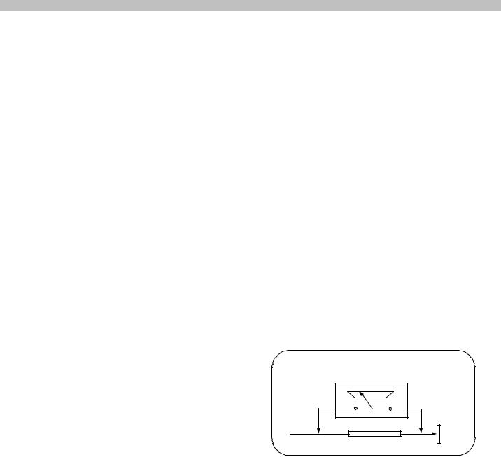
HOT CHECK CIRCUIT
|
AC-Voltmeter |
TO INSTRUMENTS |
|
EXPOSED |
Water pipe |
METALLIC PARTS |
|
|
(earth) |
|
2 K Ohm |
Figure 1
X-RAY RADIATION WARNING
The primary source of X-ray radiation in this receiver is the picture tube. The chassis is specially constructed to limit X-ray radiation. For continued X- ray radiation protection, replace the tube with the same type of the original one.
CAUTION
AFTER REMOVAL OF THE ANODE CAP, DISCHARGE THE ANODE OF THE PICTURE TUBE AND THE ANODE CAP TO THE METAL CHASSIS, CRT SHIELD, OR THE CARBON PAINTED ON THE CRT WITH A HIGH VOLTAGE PROBE
AND MULTIMETER (SELECT VDC) AND THEN SHORT |
|
CIRCUIT DIRECTLY TO DISCHARGE COMPLETELY |
||||
|
2. |
|
TECHNICAL SPECIFICATIONS |
|
. |
|
Power source: |
220-240V AC, 50-60Hz |
|
||||
Power consumption (nom.) : |
40 W |
14” |
|
|||
|
|
|
|
50 W |
20”, 21” |
|
Standby power consumption : |
4 W |
|
|
|||
Aerial impedance : |
75Ohm, coaxial type |
|
||||
Receiving system 1: |
PAL BG |
|
|
|||
|
|
|
|
PAL SECAM BG |
|
|
|
|
|
|
PAL SECAM BG DK |
|
|
|
|
|
|
PAL I |
|
|
Receiving channels: |
VHF BAND I |
CH2-4 |
|
|||
|
|
|
|
VHF BAND III |
CH5-12 |
|
|
|
|
|
CABLE TV |
S1-41 |
|
|
|
|
|
UHF BAND |
CH21-69 |
|
Audio outputs : |
2.0W RMS at %10 THD |
14” |
||||
|
|
|
|
2.5W RMS at %10 THD |
20”, 21” |
|
High Voltage : |
23 ± 0.5 KV |
|
14” |
|||
|
|
|
|
25 ± 0.5 KV |
|
20”, 21” |
Focus voltage : |
%25.6 ± %38 of EHT |
|
||||
Grid 2 voltage : |
0-1400 V |
|
|
|||
Heater voltage : |
6.2 ± 0.2 Vrms |
|
|
|||
Video/Audio Terminals : |
AV1 IN |
|
Video : 1 Vpp,75 Ohm |
|||
|
|
|
|
|
|
Audio : 0.5 Vrms, >10 Kohm |
|
|
|
|
|
|
RGB |
|
|
|
|
AV1OUT |
|
Video : 1 Vpp, 75 Ohm |
|
|
|
|
|
|
Audio : 0.5 Vrms, <1 Kohm |
|
|
|
|
AV2 IN (RCA, optional) |
Video : 1 Vpp, 75 Ohm |
|
|
|
|
|
|
|
Audio : 0.5 Vrms, >10 Kohm |
Operating temperature : |
0-45 Degrees |
|
|
|||
Safety : |
IEC 65 /BS P2N |
|
|
|||
X-Ray radiation : |
ACC. IEC 65/BS P2N |
|
||||
1 |
|
: TV set is produced to receive “one” of these colour and sound systems. |
||||
3
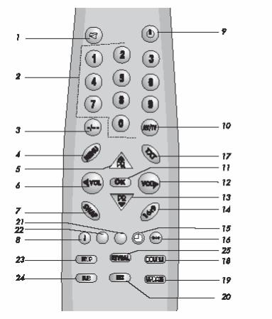
3. REMOTE CONTROL |
. |
|
1. |
MUTE button |
|
2. |
Ten key program button |
|
3. |
Two digit program button (-/--) |
|
4. |
MENU button |
|
5. |
Program up button |
|
6. |
Volume decrease button |
|
7. |
Return to selected programme button (SWAP) |
|
8. |
Information button (i) |
|
9. |
STAND-BY button |
|
10. |
AV-TV selection button |
|
11. |
OK button |
|
12. |
Volume increase button |
|
13. |
Program down button |
|
14. |
16:9 picture format button |
|
15. |
Sleep timer button |
|
16. |
Normalization button |
|
|
For Teletext Function (Opt.) |
|
1. |
Yellow fastext button |
|
2. |
Blue fastext button |
|
3. |
Teletext/TV select button |
|
4. |
Enlarge button |
|
5. |
UPDATE button |
|
6. |
MIX button |
|
7. |
Green fastext button |
|
8. |
Red fastext button |
|
9. |
STOP button |
|
10. |
SUB-PAGE button |
|
11. |
REVEAL button |
|
Special features
•Automatic Programming
•100 Programme Memory
•Available for Cable Channels (A decoder may be required)
•Manual Fine Tuning
•Skipping back to the last channel you have started to zapp via only one button(SWAP).
•16:9 picture format
•Scart Socket: Video cassette recorder, satellite receiver, video disc player, DVD, TV games or a home computer can be connected to this AV socket with an appropriate connecting cable.
•Normalization system to recall the setting in memory after the colour, contrast, brightness setting have been changed.
•Automatic Volume Limiting.
•Infrared Remote Control.
•Your TV will automatically switch off if it’s been programmed from 15 to 120 minutes.
•Automatically switch to Stand by five minutes after a channel ceases to transmit.
•Multi language menu system
•Naming the channels (Automatic with ATS).
•NTSC playback.
•S-VHS via Scart.
•ATS: Automatic Tuning System with country selection (*).
•Audio/Video RCA sockets (*).
•Headphone socket (*).
•Teletext reception (*).
•Zapping (*).
•I.P.S.: Intelligent Programme Switch: You can set your TV to skip to a specific
•Channel at a specific time. It works also as an alarm function (*).
•Childlock (*).
•Please Note: Zapping, I.P.S., Childlock are optional if ATS exists.
(*): These features are not available in all models.
4

4. PREPARATIONS |
. |
MAIN SUPPLY CONNECTIONS
Connect the TV mains plug into your domestic mains socket outlet (230 V 50Hz AC).
Press the Program up, Program down button or Numeric Buttons on the remote handset to switch the TV on.
AERIAL CONNECTION
Using a 75Ω aerial lead connect your TV to the aerial outlet in your home.
BATTERY FITTING
Insert the 2 AAA Batteries supplied into the compartment on the rear of the remote control, ensure you follow the polarity diagram inside the compartment.
PIN CONNECTIONS FOR SCART SOCKET
1- Audio output Right |
11- RGB input, Green |
2- Audio input Right |
12- |
3- Audio output Left(Mono)13- Red ground |
|
4- Audio ground |
14- Ground |
5- Blue ground |
15- RGB input, Red |
6- Audio input Left(Mono) |
16- Blanking Signal |
7- RGB input, Blue |
17- Video output ground |
8- Switching voltage |
18- Video input ground |
9- Green ground |
19- Video output |
10- |
20- Video input |
|
21- Screening |
CONNECTING TV WITH VIDEO AND SATELLITE/DIGITALRECEIVER
5
5.OPERATING YOUR TV
A.ZAPP FUNCTİON (OPTİONAL)
Select the programme you would like to recall by pressing SWAP button. Selected programme number will appear on the upper left side of the
screen. |
Watching |
any |
programme, |
you can |
recall the |
selected one by pressing SWAP button again. If you press SWAP button again, you can recall the
last programme you
watched. You can cancel ZAPP function by pressing INFO button.
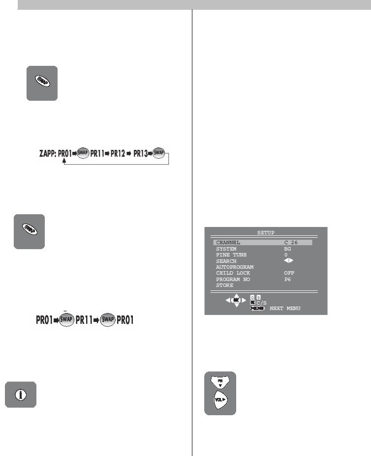
B. SWAP FUNCTION
Allows you to swap between the program you are watching and the
last selected program. i.e. If you were watching Program 1 and change to Program 11, press the
SWAP button to go back to Program 1. Press it again to return to Program 11.
Note: If Zapping function is available SWAP function will not work.
C. INFO
By pressing the “WHITE (i)” button the programme number and programme name (if it is exist) will appear on the screen. This will disappear automatically after a few seconds.
.
D. TUNING THE TELEVISION
There are two ways of tuning your television:
•Manual, where you control the tuning process or Autoprogram where the television does it all automatically.
•The TV sets equipped with ATS (Automatic Tuning System) sorts the channels regarding the broadcasting system of your country (optionally).
Please Note
If the TV is set to a channel with no signal the
TV will return to standby after 5 minutes. The time remaining is displayed on the screen.
Manual Tuning
Tuning the TV is accessed through the SETUP menu.
To access the SETUP menu:
Press the MENU button twice. SETUP Menu will appear.
a) If you don’t know the channel number (Tuning with SEARCH function).
Enter the SETUP menu by pressing MENU button twice.
In the SETUP Menu select
PROGRAM NO and change to P1 using the Program down button to select it and the Volume up or Volume down button to change it.
6
Starting with Program P1, tune in the first channel as follows:
Use the Program up button to select SEARCH.Press the Volume up or
Volume down button to start the tuning search. The search arrow will appear. When the search finds a strong searching. The picture will appear, channel signal it will stop.
Identify which channel you are watching (BBC 1, ITV 1 etc.) and decide which program number you want it to be.
Use the Program down button to select PROGRAM NO.
Use the Volume up/down buttons to select the program number.
Use the Program down button to select STORE. Press the OK button and STORED will appear on the STORE line.
You have now stored the first channel.
Use the Program up button to select again SEARCH and continue the tuning procedure until you have
tuned in all the programmes you want or the television can receive.
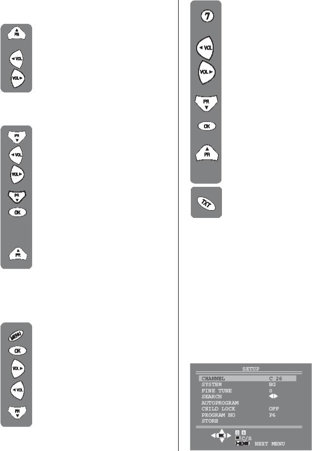
b) If you know the channel number. (Tuning with channel numbers)
Press the OK button to select “S” for cable channels and “C” for terrestrial broadcast.
Use Volume up/down button to select the channel number or enter the channel number using the Numeric buttons.
Use the Program down button to select PROGRAM NO.
Enter the desired program number by using the Ten key program buttons
Use the Volume up/down buttons to select the program number.
Use the Program down button to select STORE. Press the OK button and STORED will appear
on the STORE line. The channel will be stored with the program number you desired.
You have now stored the first channel.
Use the Program up button to select again CHANNEL and continue the tuning procedure until you have tuned in all the programmes you want or the television can receive.
To exit the SETUP menu press the
TXT button.
Please note
The system will displayed automatically on
SYSTEM row i.e.BG, L, I, DK depending the receiving broadcasting system of the country. In some countries the broadcasting system can be both in BG/DK or BG/LL´.Only the TV sets produced with Pal Secam BG/DK or Pal Secam
BG/LL´ systems can receive both BG/DK or
BG/LL´ broadcasts.
Please note
If you do not press any buttons for 15 seconds the TV will exit the menu system.
Automatic Tuning (Autoprogram)
Enter the SETUP menu as before.
7
Use the Program down button to select AUTOPROGRAM and press the OK button.
Please Note:
a)On the TV sets equipped with ATS a COUNTRY SELECTION menu will appear.
Select the desired country using Program and Volume buttons.
Press the OK button to select the country and press the OK button again the Automatic Tuning
System regarding the broadcasting system in the desired country.
b) On the TV sets without ATS pressing the OK button starts AUTOPROGRAM.
When you are sure the aerial is connected properly press the OK button and to confirm it press OK button again.
To cancel Autoprogram whilst it is working press the Menu button. As Autoprogram stores a channel it will appear briefly on the screen.
Your TV is now tuned and ready to use
E. TV SET UP
The TV set up is accessed through a menu system.
Once you have stored your set up, this is the set up the TV will default to when you switch it on.
Please note
If you do not press any buttons for 18-19 seconds the TV will exit the menu system.
There are three menus;
•Picture Menu
•Setup Menu
•Features Menu
• Picture Menu
To reach the picture menu press one time to MENU button.
BRIGHTNESS
CONTRAST
COLOUR SHARPNESS
To change, for example, the colour, select it using Program down buttons.
Use the Volume up and Volume down buttons to change the setting.
To save your settings, select STORE and press the OK button. STORED will be displayed.
Note:
If you play NTSC formatted tape from the scart, the TINT menu will appear to adjust the TINT level.
• Set up Menu
Set up menu is explained above, under “Tuning the Television” topic
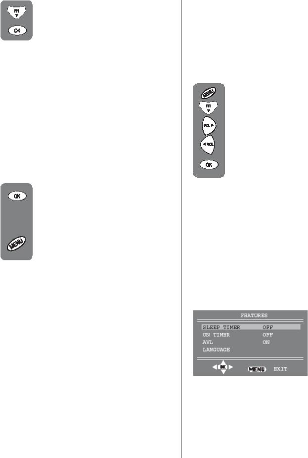
• Features Menu
To reach the feature menu press three times to MENU button.
a) Sleep Timer
The sleep timer automatically switches the set to stand-by after the preset time has elapsed.
You can select the time from 15 to 120 minutes with 15 minutes steps.
There are two ways to set the sleep timer;
8
1- Select the SLEEP TIMER in the FEATURES menu. Select the desired time by using Volume down or Volume up buttons.
2- You can also use the YELLOW ( ) button on your remote control to select this function. You can increase the switch off time interval by pressing this button repeatedly.
Notes:
The last 60 seconds of the desired switch off time by counting from 59 down. When this time interval has elapsed the set will switch to STAND-BY.
To view the remaining sleep time, press YELLOW ( ) button. To cancel the sleep time select OFF in SLEEP TIMER.
b) On Timer
You can select the on time between 30 minutes to 12 hours by pressing numeric buttons or AV button.
If TV is at Stand-by position, you can switch it on at desired time and programme by activating the ON TIMER feature.
To cancel the on time select off in ON TIMER.
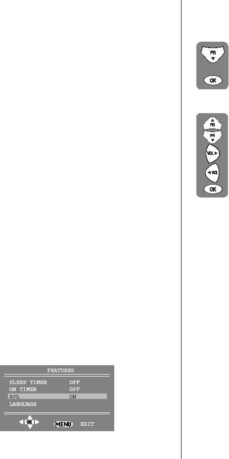
c) AVL
TV transmitters have different sound levels.
AVL (automatic volume limiting) maintains the same sound level as you switch from program to program.
From the features menu you can select AVL button by pressing Program down button.
To supply this press Volume up or down button and select ON for AVL.
d) Language
There are many languages available for the On
Screen Displays (OSD).
In the features menu select
Language by program down button.
Press the OK button to select the language list.
Press the Program up/down or Volume up/down buttons to page through all the languages and OK to select.
9
TUNER
AGC SCL SDA |
IF1 IF1 |
10
220V AC in
IC 601
TDA 16846
POWER SUPPLY
115 V 33 V 12.5 V 3.3 V
POWER AMP. |
AOUT |
|
|
|
|
IC 301 TDA 2822 |
|
|
|
|
|
KEYBOARD
EEPROM
IC 103 24CO8AN 10SI-2.7
IC 104
TDA 9830
AM DEMOD.
IR RECEIVER |
|
|
|
||
|
|
MUTE |
|
AOUT |
|
|
|
|
|
||
|
|
|
|
|
|
|
10 |
44 |
|||
|
|
|
|
|
|
5 |
|
|
|
||
51/52/53 |
|||||
6/7 TDA 9345 Tvsignal
23 processor- 8
24Teletextdecoder
3 with embedded-4647
2 Controller 48
27
IC 101
AM OUT
28 |
|
|
|
33 |
|||
|
|
|
|
34 |
|||
|
VDR A |
|
VDR B |
VGUARD |
|
|
|
|
|
|
|
||||
|
|
|
|||||
|
|
|
|
|
|
|
|
T701, T702, |
R |
|
T703 |
||
|
||
G |
||
CRT MODULE |
||
|
||
B |
||
T704, T705, |
||
|
||
|
||
T706 |
|
|
|
|
8
R
G |
SCART |
B |
AV SEL/C-VBS/AUD
H-OUT |
HORIZONTAL |
|
|
|
DEFLECTION |
H-SYNC |
2SD2599 |
|
|
VERTICAL DEFL.
IC 501
TDA 8357
SCART/FRONT AV |
A |
|
SWITCH |
||
|
||
IC 201 |
V |
|
HEF 4053 |
107 V
FBT
TR 501
EHT 45 V 12 V 8 V 5 V
CHASSIS E1 OF DIAGRAM BLOCK .6
.
 Loading...