


 HEAD OFFICE (FACTORY)
#58, SUNG SAN-DONG, CHANGWON, KYUNGNAM, KOREA TEL : (82-55) 239-7000 / FAX : (82-55) 239-7524
 OVERSEAS SALES OFFICE
#13-5, SUNG SOO 1DONG 1GA, SUNG DONG GU, SEOUL, KOREA TEL : (82-2) 498-6465 / FAX : (82-2) 467-9997

HOW TO USE THIS MANUAL
This manual describes effective maintenance procedure for the VJ125 manufactured by DAELIM Motor Co., Ltd. To ensure safety and optimal operating conditions of the vehicle, carry out regular inspections according to the maintenance schedule (Section 2).
Sections 1 through 2 provide information on overall vehicle; and section 3 describes maintenance procedure for the engine, frame and electrical systems.
To facilitate use of this manual, each page starts with disassembly and system diagrams, service information, and troubleshooting guide. If you cannot find the cause of trouble, refer to Section 21: Troubleshooting.
Contents of this manual and specifications are subject to change without prior notice for improvement of vehicle quality.
No part of this publication may be reproduced without written permission of DAELIM Motor Co., Ltd.,
ENGINE
FRAME
ELECTRICAL SYSTEM
CONTENTS
GENERAL INFORMATION
INSPECTIONS / ADJUSTMENTS
LUBRICATION
FUEL SYSTEM
COOLING SYSTEM
ENGINE REMOVAL
CLUTCH / GEARSHIFT
A.C.GENERATOR/STARTERCLUTCH
CYLINDER HEAD / VALVES
CYLINDER / PISTON
CRANKCASE / TRANSMISSION / CRANKSHAFT
EXTERNAL PARTS
FRONT WHEEL/FRONT FORK/STEERING
REAR WHEEL /REAR SUSPENSION
HYDRAULIC BRAKE
BATTERY / CHARGING SYSTEM
IGNITION SYSTEM
ELECTRIC STARTER
LIGHTS/METER/SWITCHES
WIRING DIAGRAM
TROUBLESHOOTING
1. GENERAL INFORMATION
|
|
|
|
|
|
SERVICE INFORMATION |
1-1 |
TORQUE VALUES |
1-12 |
|
|
|
|
||||
SERVICE RULES |
1-1 |
SYMBOLS / ABBREVIATIONS |
1-14 |
|
|
CAUTION WHEN WIRING |
1-5 |
TOOLS |
1-15 |
|
|
MODEL IDENTIFICATION |
1-9 |
WIRING DIAGRAM |
1-16 |
|
|
SPECIFICATIONS |
1-10 |
|
|
|
|
|
|
|
|
|
|
SERVICE INFORMATION
1.Do not run the engine for a long time in closed or not well-ventilated area because the exhaust gas contains toxic substances such as carbon monoxide, hydrocarbon, nitric oxide.
2.The battery fluid(lean sulfuric acid) is extremely toxic. It is dangerous if skin is exposed to it or if it enters into the eye. Be careful in handling. When exposed to the battery fluid, wash it with water and get a medical check up.(store the battery fluid in a safe place to avoid touching by the children)
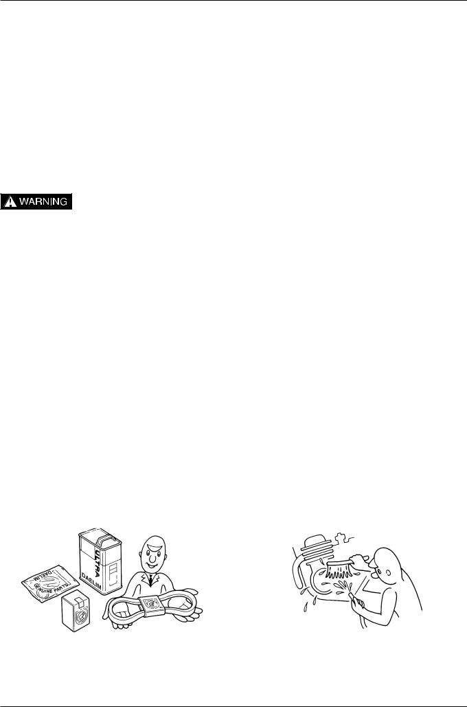
3.Pay attention not to be burned and always put on the protection gears because the engine or the muffler is hot right after engine stops.
4.Gasoline is extremely flammable. Maintenance must be performed in the place free of the open fire or electric spark.
5.When more than two person are working, always pay attention to other worker’s action and always have safety in mind.
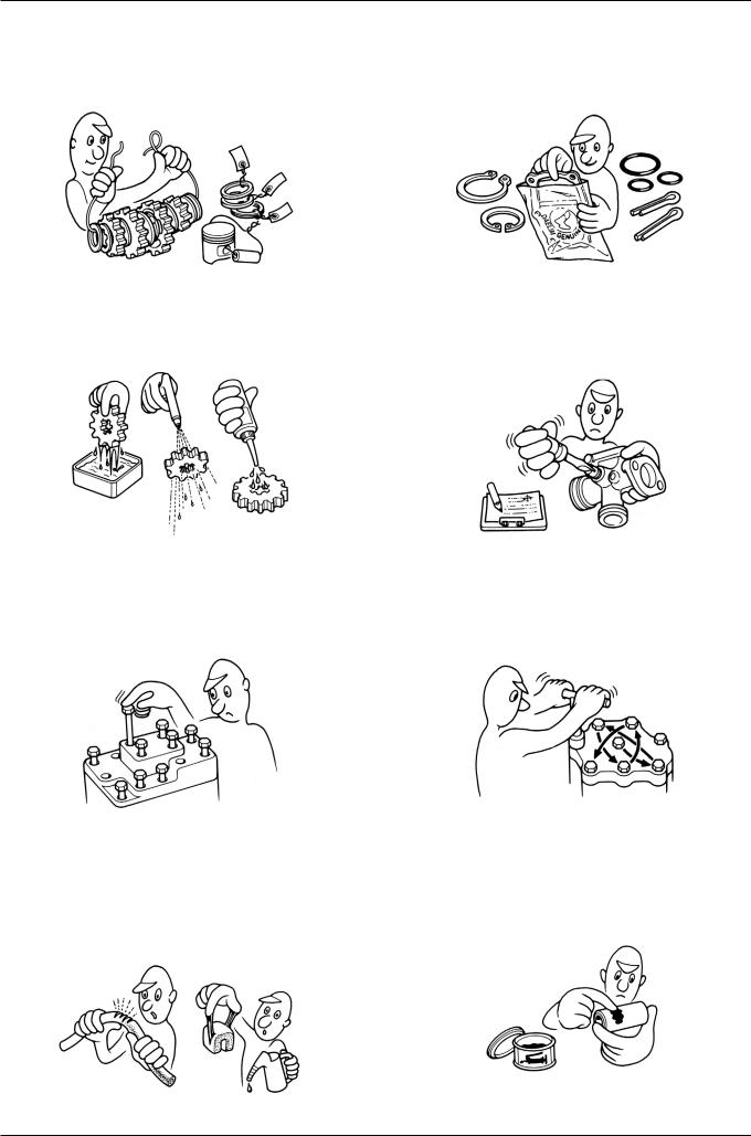
6.The skin exposed to used engine oil can be a major reason of the skin cancer. Pay attention not to be exposed and wash carefully with soap and water after handling.
7.If compressed air is used to clean the brake, dust scattered in the air can be breathed in by workers. Please take action not to scatter dust in the brake cleaner, etc.
8.Flammable nitrogen gas is generated during charging the battery so charging must be performed in well-ventilated area and free of the open fire and spark.
SERVICE RULES
1.Parts and lubrication oil must be DAELIM genuine or recommended parts.
2.Before maintenance, remove deposit or dust from the chasis.
1-1
GENERAL INFORMATION
3.Store the parts of each system discriminatively to install each part in the right place.
5.Clean the parts after the overhaul and before the test and remove the cleaning oil with compressed air. Apply oil to seal face during installation.
7.Align the bolts to uniform the tightening points before tightening them when you don’t know the bolt length.
9.Check to see if the rubber part is worn out when removing it and replace it if necessary. Some rubber part is weak to gasoline and kerosene, so pay attention not to soak with gasoline or oils.
4.After removing gasket, O-ring, piston pin clip and cotter pin, always replace them with the new one. When removing the snap ring, it can be easily missed after transformation or installation.
6.Check necessary place and measure necessary data during installation. When installing, return to the state before removing.
8.Bolts, nuts and pieces must be tightened from the bigger diameter to the smaller one, from inside to outside and diagonally with the specified torque.
10.Recommended grease must be applied to or filled in the specified place.
1-2
GENERAL INFORMATION
11.Maintenance needed to use the specialized tools must be performed with the right tool.
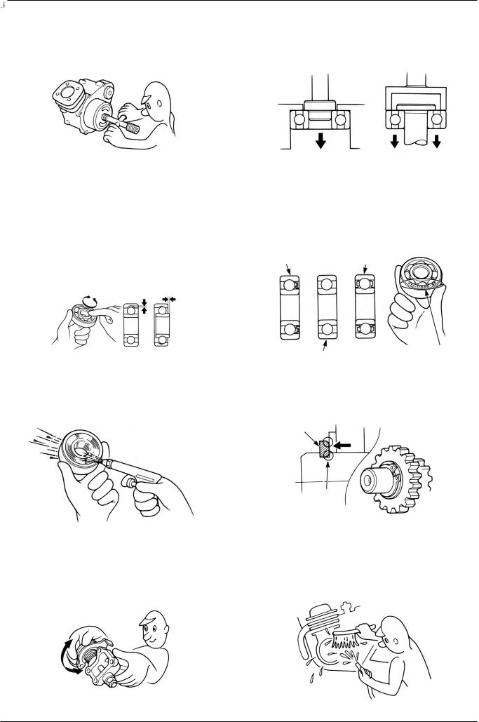
13.Check the smooth rotation of inner or outer race of the ball bearing by rotating it manually.
Replace the ball bearing having excessive axial/ longitudinal hanging.
Wipe the ball bearing likely to have hanging with cleaning oil.(except double-sided sealed type ball bearing)
Replace the ball bearing of which press-fitted part is slacked at the case or shaft.
15.When blowing the ball bearing with compressed air after cleaning, keep the race from rotating. High speed rotation of the race may damage the bearing. Prior to installation, apply oil or grease to the bearing.
17.Check each part for proper tightening and operation after installation.
12.Never reuse the ball bearing removed with the ball applied pressure when removing press-fitted the bearing.
14.Pay attention to installation direction in case of the single-sided sealed ball bearing. Install the opendirection or double-sided sealed bearing in the way that the face marked with manufacturer and size should direct to the outer axle.
’
16.Install the snap ring so that chamfered side directs to the load-applied side. After installation, check the proper installation by rotating the snap ring.
18.The brake fluid and coolant can damage the painted plastic or rubber parts. Keep these parts from contacting with them and wash these parts with water in case of contact.
1-3
GENERAL INFORMATION
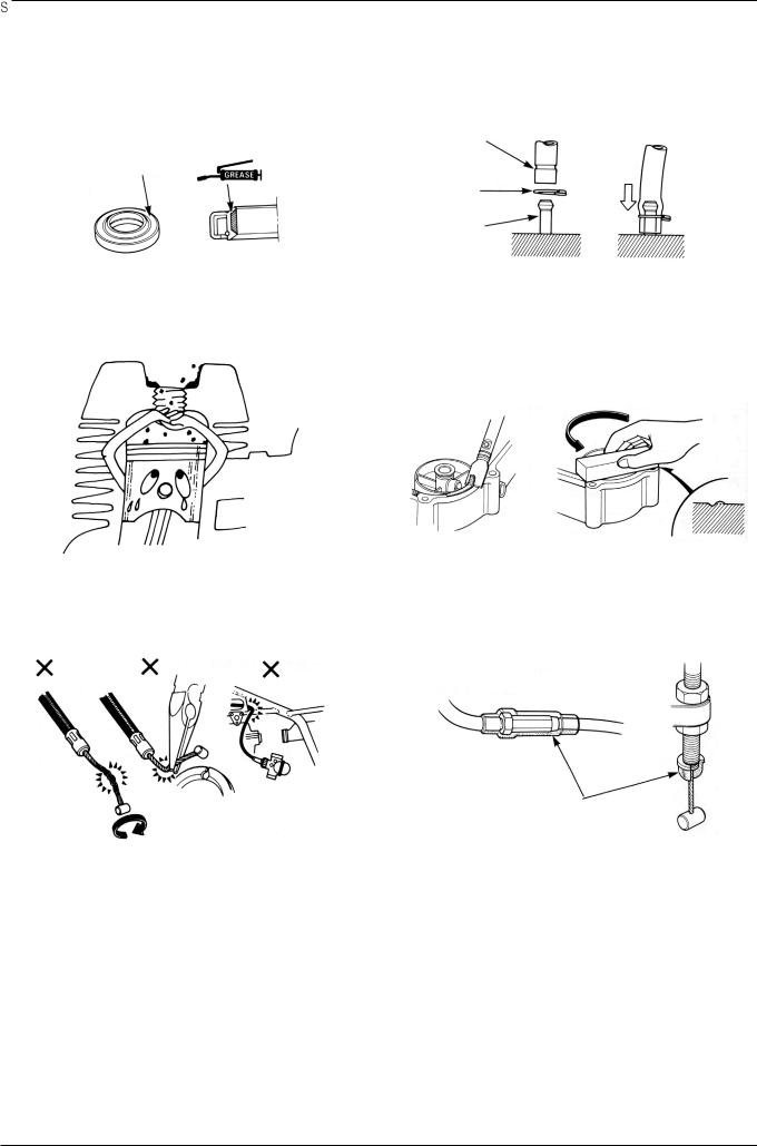
19.Install the oil seal so that the manufacturer marked surface directs outer surface.(direction not covered with oil)
Pay attention not to bend or damage the lip. Apply the grease to the lip.
20.Connect the tube until the tube fully inserted in the joint. Install the clip if it is supplied. Replace the tube having slacked end.
’
21.Keep the pneumatic system interior or the engine interior from the infiltration of dust.
23.Pay attention not to bend the cable excessively. Transformed or damaged cable may cause malfunction or damage.
22.Install the gasket mounted in the contact surface of each case of the engine while removing gasket material completely. Remove damaged contact surface by wiping with the oil stone equally.
24.Install the boots with the installing groove by inserting the boots into the groove.
1-4
GENERAL INFORMATION
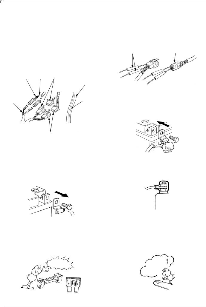
CAUTION WHEN WIRING
Each cord must be connected depending on its color. When connecting different cord, attach color tube around the connector. Connect the coupler to the connector with same color and same pin number.
Identify the two-colored cord by main color first and then spriped color .
When measuring voltage or resistance of the cord terminal using tester, contact the tester plug behind of the coupler. Pay attention not to open the cord terminal and contact the tester plug from the front of the coupler in case of water-proof coupler.
Recheck the condition of contact, securing and continuity of each part after maintenance.
When connecting the battery, the plus terminal must be connected first.
After connecting the terminal, apply the grease to the terminal.
When disconnecting the battery, the minus terminal must be disconnected first.
Make sure that the tool such as spanner do not contact with the frame.
If the fuse is short-circuited, find out the cause and repair. Replace with the fuse having the specified capacity.
Connect covers to the terminal after maintenance.
If there is rust in the terminal, remove the rust with sand paper prior to connecting.
VALIDATION |
REMOVE |
OF CAPACITY! |
THE |
|
|
|
RUST! |
1-5
GENERAL INFORMATION
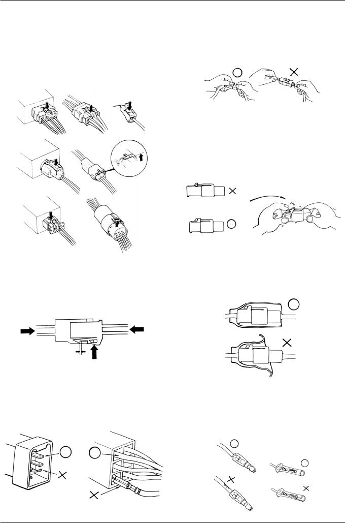
Turn off the main switch before connecting/disconnecting.
Release the lock to disconnect the lock of the coupler. The lock of the coupler has two types according to releasing method(press type and pull type) so release it properly according to the shape.
-Typical releasing method of the coupler is illustrated in the following.
Release the lock by inserting the coupler slightly and then narrowing connection to remove the coupler.
Check to see if there is bended terminal and secure it to avoid disconnecting.
When disconnecting the coupler, disconnect it while holding the coupler body. Pull while holding the wire harness cord and do not remove the coupler connection.
Insert the lock of the coupler until the lock is fully secured.
Pay attention not to damage the vinyl cover of the coupler.
If the wire harness coating is damaged, repair by winding vinyl tape or replace it.
Prior to connecting the connector, make sure that the cover is not damaged and the mess terminal is not opened.
1-6
GENERAL INFORMATION
Insert the connector until the vinyl cover is fully inserted into the terminal.
The opening of the vinyl cover must face at the ground direction but in case of the plain connector, the draining opening must face at the sky direction.
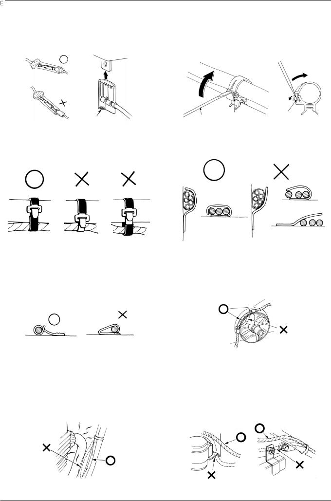
Wire band must be secured firmly in the specified location of the frame. In case of aluminium band, secure the wire harness to the coated part.
In case of the weld clamp, do not clamp in the welded part.
When clamping the wire, pay attention not to contact with hot part.
When removing T-start, broaden the groove of T-start using the wiring driver and release the torque.
Connect the harness and the hose to T-start and then insert until the groove is locked.
When removing T-start from the frame, replace it with the new one.
Secure the wire harness firmly using the clamp.
When clamping the wire harness, make sure that the harness is not contacted with the shaft or rotating part.
The wire harness must be routed without contacting with the end of the lamp or any sharp edge.
The wire harness must be routed without contacting with the end of the bolt or the piece.
1-7
GENERAL INFORMATION
In case that the wire harness is contacted with the end or the sharp edge, protect both parts with tube or tape.
The wire must not hang down or be pulled excessively.
NOT TO
PULL!
If necessary, lock the wire harness properly.
Do not twist the wire harness.
Prior to using the tester, please read the manual carefully and understand the contents.
When testing the resistance of the tester, the zero adjustment must be performed before testing.
Is this measurement range or configuration in accord
with the manual?
When mounting parts, make sure that the wire harness is not pressed by the parts.
Wire the wire harness not to be pulled or expanded when the handle is turned to the right or the left completely. Avoid excessive bending or chewing and interference with the engine.
Do not drop or throw the parts especially semiconductor contained parts because these parts may be damaged by the impact of the drop.
1-8
GENERAL INFORMATION
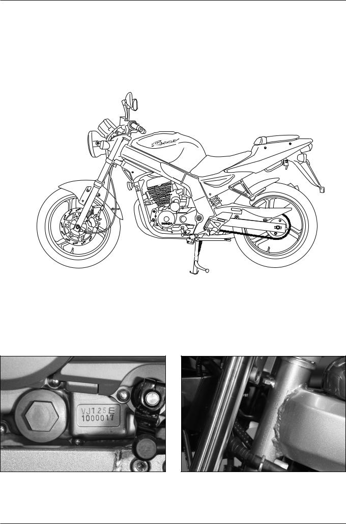
MODEL IDENTIFICATION
ENGINE SERIAL NUMBER LOCATION
The engine serial number is stamped on left crankcase.
FRAME SERIAL NUMBER LOCATION
The frame serial number is stamped on the left side of steering head.
1-9

GENERAL INFORMATION
SPECIFICATIONS
|
ITEM |
|
|
|
SPECIFICATIONS |
|
|
|
|
||
|
OVERALL LENGTH |
|
2,010mm |
||
|
OVERALL WIDTH |
|
740mm |
||
DIMENSIONS |
OVERALL HEIGHT |
|
1,040mm |
||
WHEEL BASE |
|
1,380mm |
|||
|
SEAT HEIGHT |
|
780mm |
||
|
GROUND CLEARANCE |
|
150mm |
||
|
DRY WEIGHT |
|
130kgf |
||
|
CURB WEIGHT |
|
147kgf |
||
|
|
|
|
||
|
TYPE |
|
Double Cradle |
||
|
FRONT SUSPENSION / STROKE |
Telescopic / 130mm |
|||
|
REAR SUSPENSION / STROKE |
Swingarm / 28mm |
|||
|
FRONT TIRE SIZE (TYPE) |
110/70-17 54P (Tubeless) |
|||
|
REAR TIRE SIZE (TYPE) |
|
140/60-17 69P (Tubeless) |
||
|
TIRE PRESSURE 1 PERSON FRONT |
2.00kgf/cm2(200kPa) |
|||
FRAME |
|
REAR |
2.00kgf/cm2(200kPa) |
||
2 PERSON FRONT |
2.00kgf/cm2(200kPa) |
||||
|
|
REAR |
2.25kgf/cm2(225kPa) |
||
|
FRONT BRAKE |
|
Hydraulic Disk |
||
|
REAR BRAKE |
|
Hydraulic Disk |
||
|
FUEL CAPACITY |
|
16 |
|
|
|
FUEL RESERVE CAPACITY |
1.1 |
|
|
|
|
CASTER ANGLE |
|
25.2 |
|
|
|
TRAIL |
|
93.5mm |
||
|
FRONT FORK OIL CAPACITY |
265 |
|
2.5cc |
|
|
|
|
|
||
|
TYPE |
|
Air Cooled 4-stroke SOHC |
||
|
CYLINDER NUMBER, ARRANGEMENT |
1 Cylinder, 15 Inclined from vertical |
|||
|
BORE AND STROKE |
|
56.5 X 49.5mm |
||
|
DISPLACEMENT |
|
124.1cm3 |
||
|
COMPRESSION RATIO |
|
10.7:1 |
||
|
VALVE TRAIN |
|
SOHC Chain Drive |
||
|
OIL CAPACITY |
|
1.1 |
|
After Disassembly |
ENGINE |
|
|
1.05 After Draining and Oil Filter Change |
||
|
|
1.0 |
|
After Draining |
|
|
LUBRICATION SYSTEM |
|
Wet Pressing and Spray |
||
|
AIR FILTRATION TYPE |
|
Paper Filter |
||
|
CYLINDER COMPRESSION |
13.0kgf/cm2 (600rpm) |
|||
|
INTAKE VALVE |
OPEN |
6 BTDC |
||
|
|
CLOSED |
22 |
ABDC (1.12mm Lift) |
|
|
EXHAUST VALVE |
OPEN |
24 |
BBDC |
|
|
|
CLOSED |
-4 |
ATDC (1.12mm Lift) |
|
|
VALVE CLEARANCE |
INTAKE |
0.12 |
0.02mm |
|
|
(A COOLING-OFF PERIOD) EXHAUST |
0.12 |
0.02mm |
||
|
ENGINE DRY WEIGHT |
|
32.3kgf |
||
|
|
|
|
|
|
1-10

GENERAL INFORMATION
|
ITEM |
|
SPECIFICATIONS |
|
|
|
|
|
TYPE |
PD 24 |
|
|
VENTURI BORE |
24mm |
|
|
SETTING SERIES MARK |
VJ 125 C |
|
|
MAIN JET |
#100 |
|
CARBURETOR |
SLOW JET |
#38 |
|
|
PILOT SCREW INITIAL SETTING |
2 1/8 |
|
|
FLOAT LEVEL |
12.5mm |
|
|
IDLE SPEED |
1,600 100(rpm) |
|
|
|
|
|
|
CLUTCH TYPE |
Multiplate Wet Clutch |
|
|
TRANSMISSION TYPE |
Constant Mesh Transmission |
|
|
GEAR RATIO 1st |
3.083(37/12 T) |
|
DRIVE TRAIN |
GEAR RATIO 2nd |
1.882(32/17 T) |
|
|
GEAR RATIO 3rd |
1.380(29/21 T) |
|
|
GEAR RATIO 4th |
1.095(23/21 T) |
|
|
GEAR RATIO 5th |
0.923(24/26 T) |
|
|
GEARSHIFT PATTERN |
Left foot operated return system |
|
|
|
1-N-2-3-4-5 |
|
|
|
|
|
|
IGNITION TYPE |
DC-CDI Ignition |
|
|
IGNITION TIMING “F” MARK |
8 |
BTDC / 1,600(rpm) |
|
FULL ADVANCE |
28 |
BTDC / 4,000(rpm) |
|
AC GENERATOR |
12V-11A/5,000(rpm) |
|
|
BATTERY CAPACITY |
12V 10AH |
|
|
SPARK PLUG |
CR8EH - 9 |
|
|
SPARK PLUG GAP |
0.8 - 0.9mm |
|
|
FUSE CAPACITY |
15A |
|
|
STARTING SYSTEM |
Starter Motor |
|
ELECTRICAL |
HEADLIGHT (HIGH/LOW BEAM) |
35W/35W |
|
|
POSITION LAMP |
3W |
|
|
WINKER LAMP |
10W 4 |
|
|
STOP/TAIL LIGHTS |
21W/5W |
|
|
SPEEDOMETER LAMP |
3W |
|
|
FUEL RESERVE INDICATOR LAMP |
2W |
|
|
NEUTRAL INDICATOR LAMP |
3W |
|
|
HIGH BEAM INDICATOR LAMP |
3W |
|
|
WINKER INDICATOR LAMP |
3W 2 |
|
|
LICENCE PLATE LAMP |
5W |
|
|
TACHOMETER LAMP |
2W |
|
|
|
|
|
1-11

GENERAL INFORMATION
TORQUE VALUES
ENGINE
ITEM |
Q’TY |
THREAD DIA |
TORQUE |
REFERENCE |
||
(mm) |
kgf.m,(N.m) |
|||||
|
|
|
||||
CAM SHAFT HOLDER NUT |
4 |
M8 |
1.25 |
2.0 (20) |
Apply Engine Oil |
|
CYLINDER HEAD COVER BOLT |
2 |
M6 |
1.0 |
1.0 (10) |
|
|
CAM CHAIN TENSIONER PIVOT BOLT |
1 |
M8 |
1.25 |
1.0 (10) |
|
|
CAM CHAIN TENSIONER LIFTER BOLT |
2 |
M6 |
1.0 |
1.2 (12) |
|
|
CAM CHAIN TENSIONER LIFTER SCREW |
1 |
M6 |
1.0 |
0.4 (4) |
|
|
TAPPET VALVE ADJUST HOLE CAP |
1 |
M36 |
1.5 |
1.5 (15) |
|
|
TAPPET ADJUST NUT |
4 |
M5 |
0.5 |
1.1 (11) |
|
|
PRIMARY DRIVE GEAR NUT |
1 |
M16 |
1.0 |
6.5 (65) |
Apply Engine Oil |
|
CLUTCH LOCK NUT |
1 |
M16 |
1.0 |
6.5 (65) |
Apply Engine Oil |
|
FLYWHEEL BOLT |
1 |
M10 |
1.25 |
5.5 (55) |
Apply Engine Oil |
|
STARTER CLUTCH SOCKET BOLT |
3 |
M8 |
1.25 |
3.2 (32) |
|
|
BEARING SET PLATE BOLT |
2 |
M6 |
1.0 |
1.2 (12) |
|
|
OIL FILTER COVER SOCKET BOLT |
1 |
M10 |
1.25 |
1.2 (12) |
|
|
SHIFT DRUM STOPPER ARM BOLT |
1 |
M6 |
1.0 |
1.2 (12) |
|
|
DRIVE SPROCKET BOLT |
2 |
M6 |
1.0 |
1.2 (12) |
|
|
R. CRANKCASE COVER BOLT |
11 |
M6 |
1.0 |
1.1 (11) |
|
|
OIL FILTER COVER BOLT |
3 |
M6 |
1.0 |
1.1 (11) |
|
|
L. CRANKCASE COVER BOLT |
7 |
M6 |
1.0 |
1.1 (11) |
|
|
A.C GENERATOR CAP |
1 |
M14 |
1.5 |
0.6 (6) |
|
|
CRANKSHAFT HOLE CAP |
1 |
M30 |
1.5 |
0.8 (8) |
|
|
CRANKCASE BOLT |
10 |
M6 |
1.0 |
1.1 (11) |
|
|
SPARK PLUG |
1 |
M10 |
1.25 |
1.1 (11) |
|
|
OIL PUMP MOUNT BOLT |
2 |
M6 |
1.0 |
1.1 (11) |
|
|
START MOTOR NUT |
1 |
M6 |
1.0 |
1.2 (12) |
|
|
OIL THROUGH BOLT(CYLINDER) |
2 |
M12 |
1.25 |
3.2(32) |
|
|
OIL THROUGH BOLT(RADIATOR) |
2 |
M12 |
1.25 |
3.2(32) |
|
|
AIR CLEANER CASE COVER SCREW |
4 |
M5 |
12 |
0.4(4) |
|
|
FRAME
ITEM |
Q’TY |
THREAD DIA |
TORQUE |
REFERENCE |
|
(mm) |
kgf.m,(N.m) |
||||
|
|
|
ENGINE HANGER BOLT (REAR) |
2 |
M10 |
1.25 |
4.9 (49) |
|
ENGINE HANGER BOLT (FRONT) |
1 |
M10 |
1.25 |
4.9 (49) |
|
STEERING HANDLE PIPE BOLT |
2 |
M8 |
1.25 |
2.6 (26) |
|
SIDE STAND PIVOT SCREW |
1 |
M10 |
1.25 |
1.5 (15) |
|
SIDE STAND PIVOT NUT |
1 |
M10 |
1.25 |
4.5 (45) |
HEX NUT |
SPEEDOMETER GEAR BOX SCREW |
1 |
M 5 |
0.8 |
0.42 (4.2) |
|
REAR AXLE NUT |
1 |
M14 |
1.5 |
8.8(88) |
U- NUT |
DRIVE SPROCKET NUT |
4 |
M10 |
1.25 |
5.9(59) |
U- NUT |
REAR BRAKE OIL BOLT |
2 |
M10 |
1.25 |
3.4(34) |
|
1-12

GENERAL INFORMATION
FRAME
ITEM |
Q’TY |
THREAD DIA |
TORQUE |
REFERENCE |
|
(mm) |
kgf.m,(N,m) |
||||
|
|
|
REAR CALIPER BRACKET BOLT |
2 |
M8 |
1.25 |
3.0(30) |
|
REAR MASTER CYLINDER HOLDER SOCKET BOLT |
2 |
M6 |
1.0 |
1.2(12) |
|
FRONT AXLE NUT |
1 |
M14 |
1.5 |
5.9(59) |
U- NUT |
FRONT BRAKE DISK BOLT |
6 |
M8 |
1.25 |
4.2(42) |
|
BRAKE OIL BOLT (FRONT/REAR) |
4 |
M10 |
1.25 |
3.4(34) |
|
CALIPER BRACKET BOLT (FRONT/REAR) |
4 |
M8 |
1.25 |
3.0(30) |
|
FRONT MASTER CYLINDER HOLDER BOLT |
2 |
M6 |
1.0 |
1.2(12) |
|
STEERING STEM NUT |
1 |
M22 |
1.0 |
7.4(74) |
|
STEERING TOP THREAD |
1 |
M22 |
1.0 |
0.3(3) |
|
FORK TOP BRIDGE PINCH BOLT |
2 |
M8 |
1.25 |
2.6(26) |
|
BOTTOM BRIDGE PINCH BOLT |
2 |
M8 |
1.25 |
3.4(34) |
|
FORK HANDLE PIPE MOUNTING BOLT |
2 |
M8 |
1.25 |
2.6(26) |
|
SWINGARM PIVOT NUT |
1 |
M14 |
1.25 |
8.8(88) |
U- NUT |
REAR CUSHION UPPER/UNDER BOLT |
2 |
M10 |
1.25 |
3.4(34) |
|
CHAIN SLIDER SCREW |
2 |
6mm Tapping |
0.6(6) |
|
|
L. DOWNTUBE COMP ‘B’ |
4 |
M8 |
1.25 |
4.2(42) |
SOCKET BOLT |
HANDLE WEIGHT SOCKET BOLT |
2 |
M8 |
1.25 |
2.0(20) |
|
REAR BRAKE DISK BOLT |
3 |
M8 |
1.25 |
4.2(42) |
|
Torque specifications listed above are for important fastener. Other should be tighten to the standard torque values below.
TYPE |
|
TORQUE |
TYPE |
TORQUE |
|||
|
|
|
|
|
|||
kgf |
m |
N m |
kgf m |
N m |
|||
|
|
||||||
|
|
|
|
|
|
|
|
15mm BOLT, NUT |
0.5 |
|
5 |
5mm SCREW |
0.4 |
4 |
|
16mm BOLT, NUT |
1.0 |
|
10 |
6mm SCREW, FLANGE BOLT |
0.9 |
9 |
|
18mm BOLT, NUT |
2.1 |
|
21 |
6mm FLANGE BOLT, NUT |
0.9 |
9 |
|
10mm BOLT, NUT |
3.5 |
|
35 |
8mm FLANGE BOLT, NUT |
2.7 |
27 |
|
12mm BOLT, NUT |
5.5 |
|
55 |
10mm FLANGE BOLT, NUT |
4.0 |
40 |
|
|
|
|
|
|
|
|
|
1-13
GENERAL INFORMATION
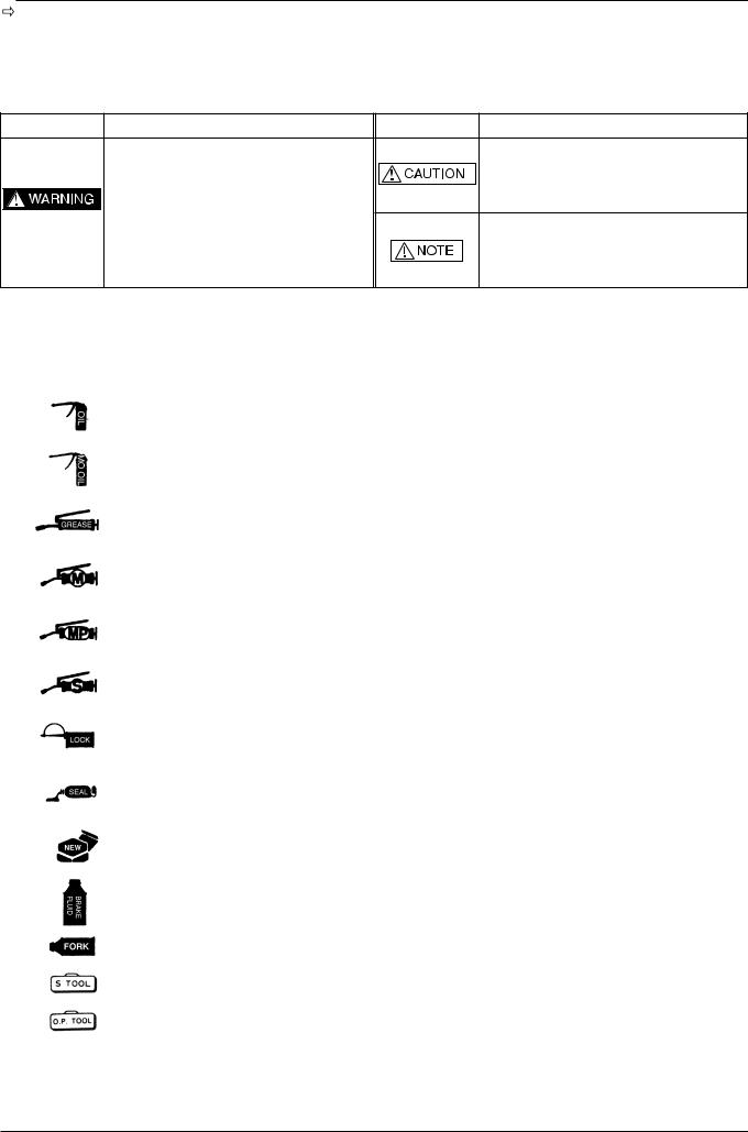
SYMBOLS / ABBREVIATIONS
The following symbols are used in this manual to represent job-related warnings or cautions.
SYMBOL |
MEANING |
SYMBOL |
MEANING |
|
|
|
Indicates important work. Minor injury or |
Indicates |
dangerous area. Serious |
|
vehicle part damage may result if instruction |
accident may result if instructions are not |
|
are not followed. |
|
followed. |
|
|
Indicates general safety matters. Provides |
|
|
|
safety and appropriate handling procedures. |
The following symbols indicate needed lubrication steps, the changing of parts, and required specialized tools, etc. when performing maintenance.
SYMBOL |
CAUTION |
|
|
|
Use recommended engine oil, unless otherwise specified. |
|
|
|
Use molybdenum oil solution (mixture of the engine oil and molybdenum grease with the ratio 1:1) |
|
|
|
Use multi-purpose grease (Lithium based multi-purpose grease NLG #2 or equivalent) |
|
|
|
Use molybdenum disulfide grease (containing more than 3% molybdenum disulfide, NLGI #2 |
|
or equivalent) |
|
|
|
Use molybdenum disulfide paste containing more than 40% molybdenum disulfide, NLGI #2 or |
|
equivalent) |
|
|
|
Use silicone grease |
|
|
|
Apply a locking agent. Use the agent of the middle strength, unless otherwise specified |
|
|
|
Apply sealant |
|
|
|
Replace the parts with new ones before assembly |
|
|
|
Use brake fluid, DOT3 or DOT4. Use the recommended brake fluid, unless otherwise specified |
|
|
|
Use Fork or Suspension Fluid |
|
|
|
Use special tool |
|
|
|
Use option tool. These tools are obtained as you order parts. |
|
|
( 3-1) |
Indicates reference page. (Example : Refer to page 3-1) |
|
|
Special grease, etc. that do not correspond to the above are indicated without using symbols.
1-14

GENERAL INFORMATION
TOOLS
SPECIAL |
|
COMMON |
|
|
|
|
|
DESCRIPTION |
REF. SEC. |
DESCRIPTION |
REF. SEC. |
CLUTCH CENTER HOLDER |
7 |
WRENCH, 8 9mm |
2 |
ACG ROTOR PULLER |
8 |
ADJUSTING WRENCH, B |
2 |
VALVE GUIDE DRIVER |
9 |
FLOAT LEVEL GAUGE |
4 |
VALVE GUIDE REAMER |
9 |
LOCK NUT WRENCH, 20 24mm |
7 |
UNIVERSAL BEARING PULLER |
11 |
EXTENSION BAR |
7, 13 |
BEARING REMOVER SET |
11 |
FLY WHEEL HOLDER |
7, 8 |
THREAD ADAPTER |
11 |
VALVE SPRING COMPRESSOR |
9 |
ASSEMBLY SHAFT |
11 |
DRIVER |
11, 13, 14 |
CRANK CASE ASSEMBLY COLOR |
11 |
ATTACHMENT |
11, 13, 14 |
BALL RACE DRIVER |
13 |
PILOT |
11, 13, 14 |
STEERING STEM DRIVER |
13 |
FORK SEAL DRIVER BODY |
13 |
FORK SEAL DRIVER |
13 |
BEARING REMOVER HEAD |
14 |
STEERING STEM SOCKET |
13 |
BEARING REMOVER SHAFT |
14 |
SNAP RING PLIERS |
15 |
|
|
|
|
|
|
TESTER, GAUGE
DESCRIPTION |
REFERENCE SECTION |
REMARK |
|
|
|
COMPRESSION GAUGE |
2 |
|
DIGITAL MULTI TESTER |
16, 17 |
|
PVA TESTER |
16, 17 |
|
BATTERY TESTER |
17 |
|
|
|
|
VALVE SEAT CUTTER
DESCRIPTION |
REFERENCE SECTION |
REMARK |
|
|
|
VALVE SEAT CUTTER 45 |
9 |
24.5mm IN, EX |
VALVE SEAT CUTTER 35 |
9 |
23mm IN |
VALVE SEAT CUTTER 35 |
9 |
20mm EX |
VALVE SEAT CUTTER 60 |
9 |
22mm IN, EX |
CUTTER HOLDER 5mm |
9 |
Use with Valve Seat |
|
|
|
1-15
GENERAL INFORMATION
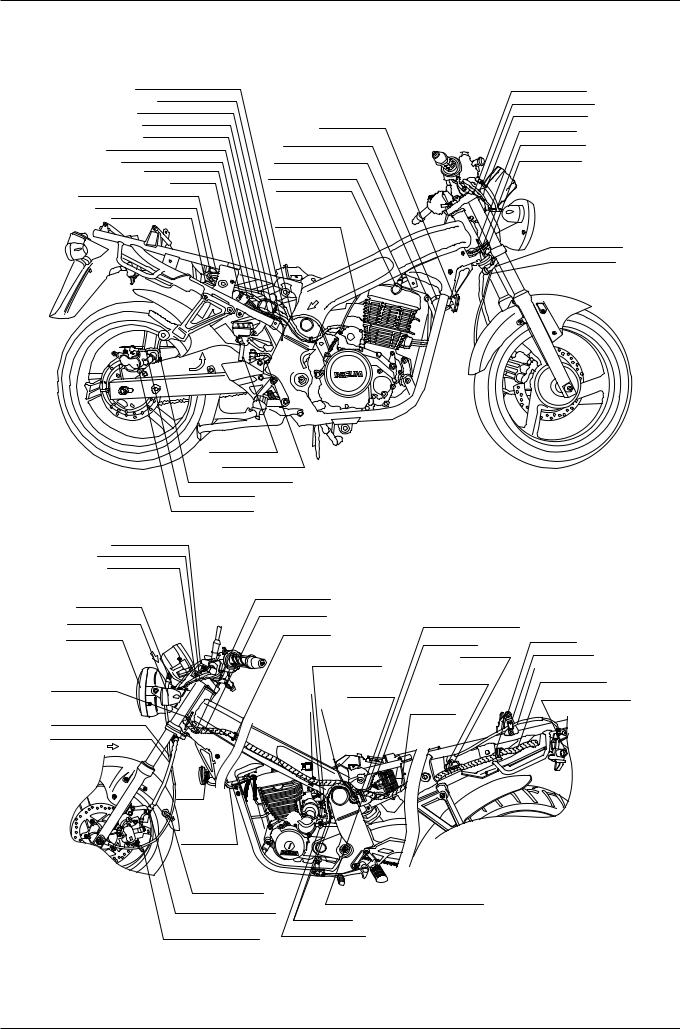
WIRING DIAGRAM
BATTERY EARTH CABLE |
|
|
ST.-MOTOR CABLE |
|
|
SIDE STAND SW. CORD |
|
|
RR. STOP SW. CORD |
HORN COMP. |
|
ST.-MAG SW. CORD |
||
LH. RADIATOR HOSE |
||
ST.-MAG. BATTERY CABLE(+) |
||
|
||
BATTERY EARTH CABLE |
RH. RADIATOR HOSE |
|
HARNESS COVER |
HIGH TENSION CORD |
|
WIRE CLIP |
||
NOISE |
||
ST.-MAG. BATTERY CABLE(+) |
||
SUPPRESSOR CAP |
||
BATTERY EARTH CABLE |
||
|
||
ST.-MAG. SW. WIRE |
CLUTCH CABLE |
|
|
C
THROTTLE CABLE
ST.-HAZ. SW. CORD
FR. BRAKE HOSE
CABLE GUIDE
CLUTCH CABLE
CHOKE CABLE
FR. BRAKE HOSE
SPDMT. CABLE
RR. BRAKE
RESERVE TUBE
RR.BRAKE HOSE RR. BRAKE HOSE CLAMP
RR.BRAKE HOSE RR. CALIPER ASS'Y.
CLUTCH CABLE
WINKER SW. CORD
CHOKE CABLE |
|
|
|
|
|
CABLE GUIDE |
THROTTLE CABLE |
|
|
|
|
WIRE HARNESS |
|
|
|
||
LH. FR. WINKER |
|
REG. RECTIFIER WIRE |
|
||
WIRE CLIP |
|
|
|||
HEAD LIGHT |
|
EARTH WIRE |
WIRE CLIP |
||
|
|
|
|||
|
|
|
|
||
G |
|
BREATHER TUBE |
ST.-MAG. |
CABLE CLAMP |
|
|
|
SW. WIRE |
SEAT LOCK CABLE |
||
CABLE GUIDE |
DRAIN TUBE |
|
|
FUSE WIRE |
WIRE HARNESS |
|
WIRE CLIP |
FUEL UNIT WIRE |
HELMET HOLDER |
||
|
|
||||
|
|
|
|||
|
|
FUEL UNIT CORD |
|||
SPEEDOMETER |
WIRE CLAMP |
ACG. WIRE |
& SEAT LOCK ASS'Y. |
||
|
|
|
|||
CABLE |
(WIRE PIVOT) |
|
|
|
|
FR.BRAKE HOSE |
|
|
A |
|
|
|
HORN |
|
|
COMP. |
|
|
|
E |
|
HORN CORD |
|
|
WIRE GROMMET |
HARNESS COVER(ACG. CORD SETT.) |
|
BRAKE HOSE CLAMPER |
|
|
ACG. CORD |
|
|
|
|
|
SPDMT. CABLE CLAMP |
ST.-MOTOR CABLE |
|
|
|
1-16
GENERAL INFORMATION
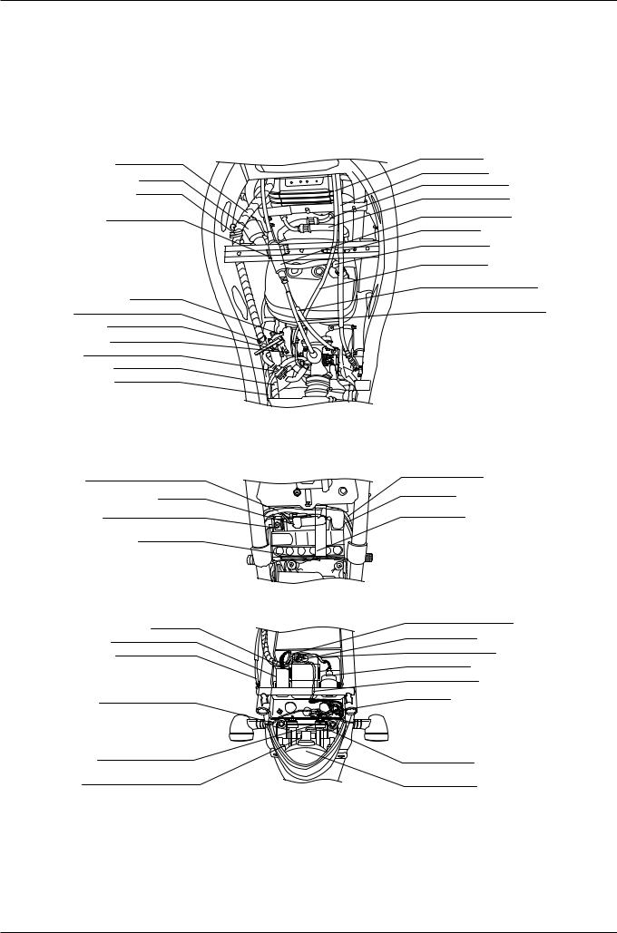
WIRE HARNESS
IGN. COIL
WIRE CLIP
THROTTLE CABLE
JUNCTION CLAMP
FUEL COCK WIRE CLAMP(WIRE PIVOT)
FUEL COCK(RES)
FUEL COCK(ON)
FUEL STRAINER COMP.
WIRE HARNESS
AIR VENT TUBE
ST.-MAG. BATTERY CABLE(+)
FUSE BOX
BATTERY EARTH CABLE
AIR VENT TUBE
CDI COMP.
HEAD LIGHT RELAY
SEAT LOCK CABLE
LH. RR. WINKER CORD
RH. RR. WINKER CORD
TAIL LIGHT SOCKET COMP.
CHOKE CABLE
CLUTCH CABLE
LH. RADIATOR HOSE
RH. RADIATOR HOSE
THROTTLE JUNCTION
CABLE GUIDE
IGN. COIL CORD
CHOKE CABLE
THROTTLE CABLE
(TO. ACCELERATION PUMP) THROTTLE CABLE(TO. CARB.)
ST.-MAG. SW. WIRE
FUSE CODE
BATTERY BAND
HEAD LIGHT RELAY WIRE
CDI COMP. WIRE
WINKER RELAY WIRE
WINKER RELAY
TAIL LIGHT WIRE
WIRE CLIP
TAIL LIGHT CORD
TAIL LIGHT ASS'Y.
1-17
GENERAL INFORMATION
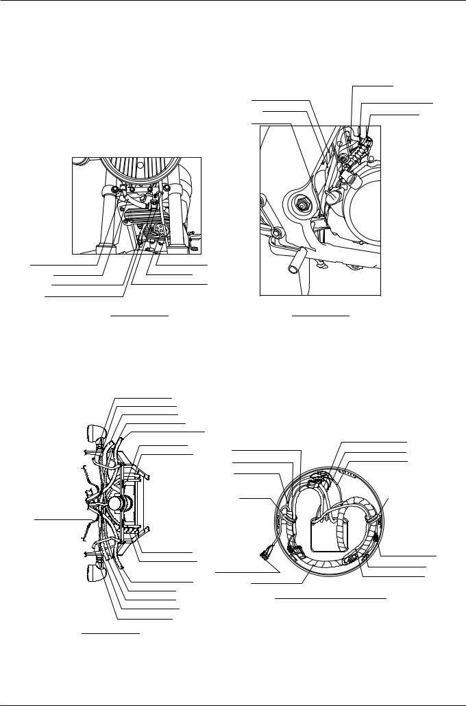
ST.-MAG. BATTERY CABLE(+) |
|
ST.-MAG. SW. WIRE |
WIRE CLIP |
BATTERY EARTH CABLE |
HARNESS COVER |
|
ST.-MAG. BATTERY CABLE(+) |
|
ST.-MAG. SW. ASS'Y. |
|
ST.-MOTOR CABLE |
|
BATTERY EARTH CABLE |
|
SIDE STAND SW. CORD |
|
RR. STOP SW. CORD |
RESERVE TANK
RR.BRAKE HOSE RR. BRAKE HOSE GUIDE
RR.BRAKE RESERVE TUBE
RR.BRAKE HOSE
DETAIL OF VIEW C
RR. CALIPER |
RESERVE TANK |
RR. BRAKE HOSE |
RR. BRAKE RESERVE TUBE |
RR.BRAKE HOSE CLAMP
RR.BRAKE HOSE GUIDE
TUBE CLIP
RR. BRAKE HOSE GUIDE
DETAIL OF VIEW B
1-18
GENERAL INFORMATION
|
DRAIN TUBE |
FUEL DRAIN TUBE |
ENG. DREATHER TUBE |
|
|
DRAIN TUBE |
CLUTCH CABLE |
|
|
TUBE GUIDE |
|
BRAKE HOSE CLAMP |
SPDMT. CABLE |
|
BRAKE HOSE |
HORN COMP. |
|
RH. RADIATOR HOSE |
SPDMT. CABLE GUIDE |
|
BRAKE HOSE CLAMPER |
|
|
DETAIL OF VIEW A |
DETAIL OF VIEW D |
|
RH. CABLE GUIDE |
|
|
|
RH. WINKER CORD |
|
|
|
FR. BRAKE HOSE |
|
|
|
THROTTLE CABLE |
|
|
|
ST. HAZARD SW. CORD |
|
|
|
CHOKE CABLE |
|
WINKER SW. CORD |
|
COMBI. METER CORD |
RH. WINKER CORD |
||
CLUTCH CABLE |
|||
|
LH. WINKER CORD |
||
|
WINKER SW. WIRE |
||
|
WINKER WIRE |
|
|
|
WIRE CLIP |
WIRE CLIP |
HEAD LIGHT CASE
WIRE HARNESS |
COMB. SW. CORD |
|
THROTTLE CABLE |
||
|
|
HEAD LIGHT WIRE |
COMB. SW. WIRE |
|
|
HAZARD SW. CORD |
||
WINKER SW. CORD |
WIRE HARNESS |
||
|
CHOKE CABLE
CLUTCH CABLE |
DETAIL OF HEAD LIGHT CASE PART |
|
|
LH. WINKER CORD |
|
LH. CABLE GUIDE |
|
DETAIL OF VIEW G |
|
1-19

MEMO

2. INSPECTIONS/ADJUSTMENTS
SERVICE INFORMATION |
2-1 |
BRAKE FLUID |
2-10 |
|
|
|
|||||
MAINTENANCE SCHEDULE |
2-3 |
BRAKE PAD WEAR |
2-10 |
|
|
FUEL LINE (FUEL TUBE) |
2-4 |
BRAKE SYSTEM |
2-11 |
|
|
|
|||||
THROTTLE GRIP OPERATION |
2-4 |
BRAKE STOP SWITCH |
2-12 |
|
|
CARBURETOR CHOKE |
2-5 |
HEADLIGHT AIM |
2-12 |
|
|
AIR CLEANER |
2-5 |
CLUTCH SYSTEM |
2-12 |
|
|
SPARK PLUG |
2-6 |
SIDE STAND |
2-13 |
|
|
VALVE CLEARANCE |
2-6 |
SUSPENSION |
2-14 |
|
|
CYLINDER COMPRESSION PRESSURE |
2-7 |
BOLTS, NUTS, FASTENERS |
2-14 |
|
|
CARBURETOR IDLE SPEED |
2-7 |
WHEELS/TIRES |
2-15 |
|
|
DRIVE CHAIN |
2-8 |
STEERING HEAD BEARINGS |
2-15 |
|
|
DRIVE CHAIN SLIDER |
2-10 |
|
|
|
|
|
|
|
|
|
|
SERVICE INFORMATION
The exhaust gas contains poisonous substance. Do not keep engine idling in a closed or poorly ventilated place for a long period of time.
For information on engine oil and oil filter, refer to sections 3-3 and 3-4.
Stand the main stand prior to beginning work.
SPECIFICATIONS
THROTTLE GRIP PLAY |
|
2~6mm |
||
|
|
|
|
|
SPARK PLUG |
|
CR8EH-9 |
||
|
|
|
|
|
SPARK PLUG GAP |
|
0.8~0.9mm |
||
|
|
|
|
|
VALVE CLEARANCE |
|
IN. |
0.12 |
0.02mm |
|
|
|
|
|
|
EX. |
0.12 |
0.02mm |
|
|
|
|||
|
|
|
|
|
CARBURETOR IDLE SPEED |
|
1,600 |
100rpm |
|
|
|
|
|
|
CYLINDER COMPRESSION |
|
13.0kgf/ ( 600rpm ) |
||
|
|
|
|
|
DRIVE CHAIN SLACK |
|
10~20mm |
||
|
|
|
|
|
REAR BRAKE PEDAL FREE PLAY |
|
10~20mm |
||
|
|
|
|
|
CLUTCH LEVER FREE PLAY |
|
10~20mm |
||
TIRES
|
DRIVER ONLY |
FRONT |
200kPa (2.00kgf/ |
) |
||
COLD TIRE |
|
|
|
|||
REAR |
200kPa (2.00kgf/ |
) |
||||
|
|
|||||
PRESSURE |
|
|
|
|
|
|
DRIVER AND A |
FRONT |
200kPa (2.00kgf/ |
) |
|||
|
|
|
|
|
|
|
|
PASSENGER |
REAR |
225kPa (2.25kgf/ |
) |
||
TIRE SIZE |
|
|
FRONT |
110/70-17 54P |
|
|
|
|
REAR |
140/60-17 60P |
|
||
|
|
|
|
|||
TIRE PART MINIMUM-DEPTH |
|
FRONT |
5.5mm |
|
||
|
REAR |
7.0mm |
|
|||
|
|
|
|
|||
|
|
|
|
|
|
|
2-1

INSPECTIONS / ADJUSTMENTS
TORQUE VALUES
SPARK PLUG |
1.1 kgf-m( 11N.m) |
CYLINDER HEAD COVER BOLT |
1.0 kgf-m( 10N.m) |
VALVE ADJUSTING NUT |
1.1 kgf-m( 11N.m) |
AC GENERATOR CAP |
0.6 kgf-m( 6N.m) |
CRANKSHAFT HOLE CAP |
0.8 kgf-m( 8N.m) |
AIR CLEANER CASE COVER SCREW |
0.43kgf-m(4.3N.m) |
REAR AXLE NUT |
8.8kgf-m(88N.m) |
DRIVE SPROCKET BOLT |
1.2kgf-m(12N.m) |
DRIVEN SPROCKET NUT |
5.9kgf-m(59N.m) |
TOOLS
WRENCH, 8 9 mm
ADJUSTING WRENCH, B
COMPRESSION GAUGE
2-2

INSPECTIONS / ADJUSTMENTS
MAINTENANCE SCHEDULE
Perform the Self Inspections Before Operation at each scheduled maintenance period.
I : INSPECT AND CLEAN, ADJUST, LUBRICATE OR REPLACE IF NECESSARY. R : REPLACE L : LUBRICATE C : CLEAN
These instructions are based on the assumption that the motorcycle will be used exclusively for its designed purpose. Sustained high speed operation, or operation in unusually wet or dusty conditions, will require more frequent service than specified in the following chart.
FREQUENCY |
ODOMETER READING(NOTE 1) |
|
|
|||
1 |
4 |
8 |
12 |
|
REMARK |
|
x 1000Km |
REFER TO |
|||||
ITEM |
|
|
|
|
|
|
MONTH |
|
6 |
12 |
18 |
PAGE |
|
FUEL LINE |
I |
I |
I |
I |
2-4 |
|
FUEL FILTER |
|
R |
R |
R |
2-4 |
|
THROTTLE GRIP OPERATION |
|
I |
I |
I |
2-4 |
|
CARBURETOR CHOKE |
|
I |
I |
I |
2-5 |
|
AIR CLEANER ELEMENT |
|
R |
R |
R |
2-5 |
NOTE (2) |
SPARK PLUG |
|
I |
R |
I |
2-6 |
|
VALVE CLEARANCE |
I |
I |
I |
I |
2-6 |
|
CARBURETOR IDLE |
I |
I |
I |
I |
2-7 |
|
ENGINE OIL |
R |
R |
R |
R |
3-3 |
|
ENGINE OIL FILTER |
R |
R |
R |
R |
3-4 |
|
DRIVE CHAIN |
|
Every 1,000 |
: I and L |
|
2-8 |
|
DRIVE CHAIN SLIDER |
|
|
I |
|
2-10 |
|
BRAKE FLUID |
|
I |
I |
I |
2-10 |
NOTE (3) |
BRAKE /PAD WEAR |
|
I |
I |
I |
2-10 |
|
BRAKE SYSTEM |
I |
I |
I |
I |
2-11 |
|
BRAKE STOP SWITCH |
|
I |
I |
I |
2-12 |
|
HEADLIGHT AIM |
|
I |
I |
I |
2-12 |
|
CLUTCH SYSTEM |
I |
I |
I |
I |
2-12 |
|
SIDE STAND |
|
I |
I |
I |
2-13 |
|
SUSPENSION |
|
I |
I |
I |
2-14 |
|
BOLTS, NUTS, FASTENERS |
I |
|
I |
|
2-14 |
|
WHEELS/TIRES |
|
I |
I |
I |
2-15 |
|
STEERING HANDLE BEARING |
I |
|
I |
|
2-15 |
|
If you do not have the appropriate tools or information to conduct maintenance, or if you feel you are not capable to perform maintenance on this vehicle, contact authorized dealers or repair shops for maintenance and repairs.
To ensure safety, inspections and maintenance of these parts must be carried out by dealers, or repair centers.
NOTES : (1) At higher odometer readings, repeat at the frequency interval established here.
(2)Service more frequently when riding in unusually wet or dusty areas.
(3)Replace every 2 years, or at indicated odometer interval, whichever comes first. Replacement requires mechanical skill.
2-3
INSPECTIONS / ADJUSTMENTS
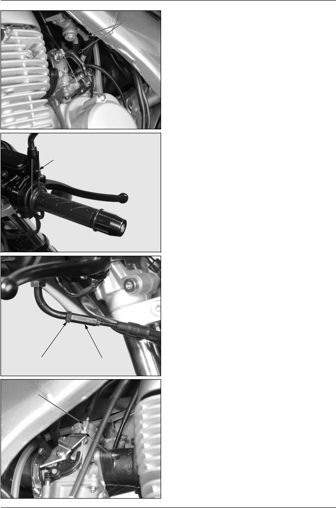
FUEL TUBE
2~6mm
LOCK NUT |
ADJUSTER |
ADJUSTER
LOCK NUT
FUEL LINE (FUEL TUBE)
Check the fuel tube for deterioration, damage or leakage. Replace it if necessary.
THROTTLE GRIP OPERATION
Check if the throttle grip operates smoothly in all steering positions.
If not operating smoothly, check the deterioration, damage and kink of the throttle cable.
Measure the free play at the throttle grip.
FREE PLAY : 2~6mm
Throttle grip free play can be adjusted at either end of the throttle cable.
Minor adjustment are made with the upper adjuster. Adjust the free play by loosening the lock nut and turning the adjuster.
Major adjustments are made with the lower adjuster. Adjust the free play by loosening the lock nut and turning the adjuster.
After adjustment, tighten the lock nut securely. Recheck the throttle operation.
Replace any damaged parts, if necessary.
2-4
INSPECTIONS / ADJUSTMENTS
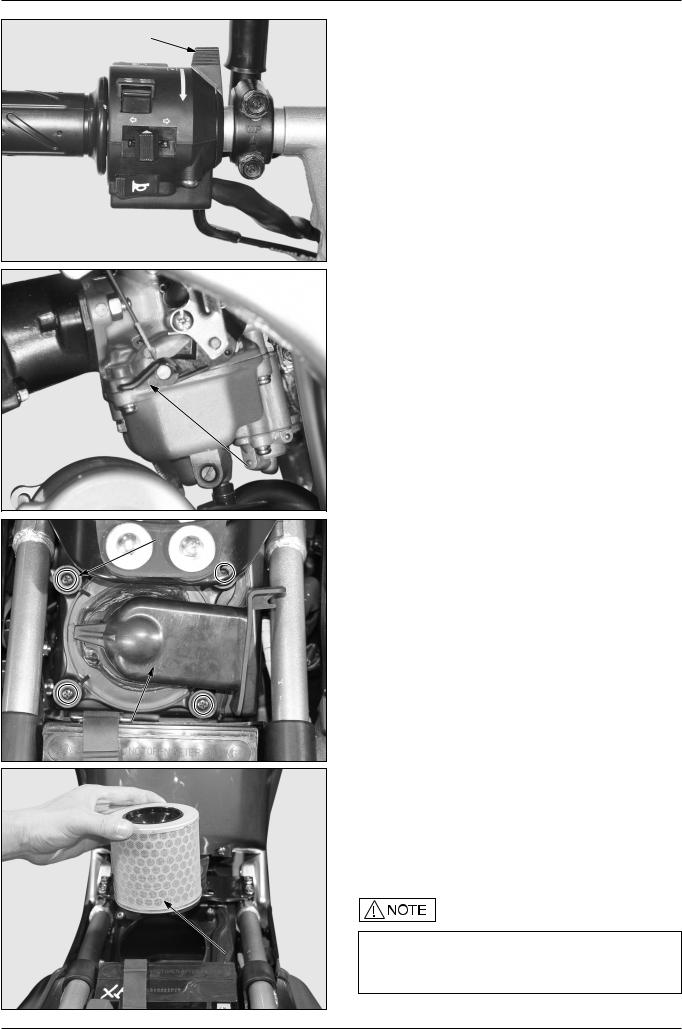
CHOKE LEVER
CHOKE ARM
SCREWS
AIR CLEANER
HOUSING COVER
AIR CLEANER
ELEMENT
CARBURETOR CHOKE
Check the deterioration, damage and kink of the choke cable. Check if the choke lever operates smoothly in any position.
Pull the choke lever to the left, and close it perfectly.
Check if the choke valve is closed perfectly by moving the carburetor choke arm.
When adjustment is necessary, loosen the choke cable clamp in order that choke valve can be opened, and then adjust by moving the choke cable cover.
AIR CLEANER
Remove the seat. ( 12-2)
Loosen the 4 screws, remove the air cleaner housing cover.
Remove and discard the air cleaner element in accordance with the maintenance schedule. ( 2-3) Also replace the air cleaner element any time it is excessively dirty or damage.
Install the removed parts in the reverse order of removal.
The element is a viscous type which contains oil. Therefore do not use compressed air to clean the air cleaner element.
2-5
INSPECTIONS / ADJUSTMENTS
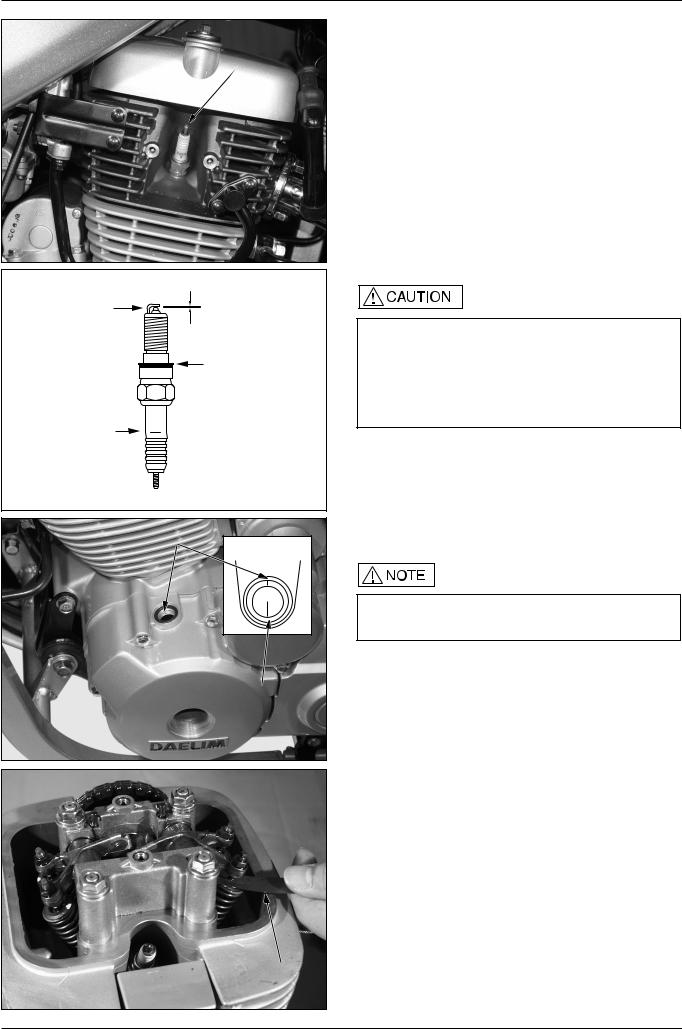
SPARK PLUG
SPARK PLUG
Remove the spark plug cap and disassemble the plug. Check the plug for damage, contamination or deposits. If the spark plug is severely contaminated or damaged, raplace with a new one. If the plug can be reused after removing only the carbon, use plug cleaner and wire brush to clean the plug.
Always use a feeler gauge to check the gap.
GENUINE PLUG : CR8EH-9
SPARK PLUG GAP : 0.8~0.9mm
TORQUE : 1.1kgf m (11N m)
CHECK GAP, |
0.8~0.9mm |
|
|
DEPOSITS |
|
|
CHECK WASHER |
|
FOR DAMAGE |
CHECK FOR |
|
CRACKS |
|
INDEX MARK
“T” MARK
FEELER GAUGE
Make sure there is no dirt or debris on the seat of the spark plug hole before inserting the spark plug.
To prevent damage to the cylinder head, handtighten the spark plug before using a wrench to tighten to the specified torque.
Do not overtighten the spark plug.
VALVE CLEARANCE
Inspect and adjust valve clearance while the engine is cold. (below 35° C/95°F)
Remove the cylinder head cover.
Remove the A.C generator cap and crankcase hole cap. Rotate the flywheel counterclockwise to align the "T" mark with the index mark on the left crankcase cover.
Make sure the piston is at TDC(Top Dead Center) on the compression stroke.
Measure the valve clearance with a feeler gauge.
VALVE CLEARANCE : INTAKE : 0.12 0.02mm
EXHAUST : 0.12 0.02mm
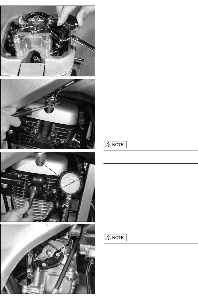
Loosen the lock nut with a vlave wrench, and set valve clearance to a prescribed level by turning the adjusting screw with a valve adjusting wrench.
After setting clearance to the prescribed level, hold the adjuster screw with a valve adjusting wrench, and tighten the lock nut.
TORQUE : 1.1kgf m (11N m)
TOOLS : WRENCH 8x9mm
ADJUSTING WRENCH B
FEELER GAUGE
2-6
INSPECTIONS / ADJUSTMENTS
ADJUSTING WRENCH B
SPARK PLUG WRENCH
Measure the vlave clearance again.
Install the cylinder head cover and tighten the bolts.
TORQUE : 1.0kgf m (10N m)
Install the A.C generator cap and crankcase hole cap.
TORQUE :
A.C GENERATOR CAP : 0.6kgf m(6N m) CRANK CASE HOLE CAP : 0.8kgf m(8N m)
CYLINDER COMPRESSION PRESSURE
Warm up the engine.
Stop the engine, and remove the spark plug cap and spark plug. Install the compression gauge.
Open the throttle completely and crank the engine with the starter motor until the gauge reading stops rising.
TOOL : COMPRESSION GAUGE
COMPRESSION GAUGE
THROTTLE STOP SCREW
The maximum reading is usually reached within 4~7 seconds
COMPRESSION PRESSURE : 13.0 f/ (600rpm)
If compression is low, check the following:
-Incorrect valve clearance adjustment
-Valve leakage
-Leakage from the cylinder head gasket.
-Worn piston/cylinder
If compression is high, check the following:
-Carbon deposits on the piston head, and cylinder head.
CARBURETOR IDLE SPEED
Inspect all other engine adjustments are within specifications and adjust idle speed.
The engine must be warm for accurate adjustment. Support the motorcycle on a level surface and shift the transmission into neutral.
Warm up the engine for about ten minutes.
Turn the throttle stop screw as required to obtain the specified idle speed.
IDLE SPEED : 1,600 100rpm
2-7
 Loading...