


TPS-6L
Table of contents
 Loading...
Crestron Isys® TPS-6L
5.7-Inch Wall Mount Touchpanel
Operations & Installation Guide

This document was prepared and written by the Technical Documentation department at:
Crestron Electronics, Inc.
15 Volvo Drive
Rockleigh, NJ 07647
1-888-CRESTRON
All brand names, product names and trademarks are the property of their respective owners.
©2007 Crestron Electronics, Inc.

Crestron Isys® TPS-6L 5.7-inch Wall Mount Touchpanel
Contents
Isys® 5.7-Inch Wall Mount Touchpanel: TPS-6L 1
Introduction ..........................................................................................................1
Features and Functions...........................................................................1
Applications ...........................................................................................3
Internal Block Diagram.......................................................................... 4
Specifications ......................................................................................... 4
Physical Description...............................................................................6
Industry Compliance ..............................................................................9
Setup................................................................................................................... 10
Network Wiring ...................................................................................10
Ethernet ................................................................................................ 10
Identity Code........................................................................................ 10
Configuring the Touchpanel.................................................................11
Mounting Options ................................................................................27
Touchpanel Mounting ..........................................................................27
Touchpanel Removal ...........................................................................31
Hardware Hookup ................................................................................ 32
Recommended Cleaning ......................................................................33
Programming Software.......................................................................................34
Earliest Version Software Requirements for the PC ............................34
Programming with Crestron SystemBuilder ........................................34
Programming with D3 Pro ...................................................................34
Programming with SIMPL Windows...................................................35
Programming with VisionTools Pro-e .................................................37
Example Program.................................................................................40
Uploading and Upgrading ..................................................................................41
Establishing Communications..............................................................41
Programs, Projects and Firmware ........................................................42
Program Checks ...................................................................................42
Problem Solving.................................................................................................43
Troubleshooting ...................................................................................43
Check Network Wiring ........................................................................44
Reference Documents ..........................................................................45
Further Inquiries...................................................................................45
Future Updates .....................................................................................45
Software License Agreement..............................................................................46
Return and Warranty Policies.............................................................................48
Merchandise Returns / Repair Service ................................................. 48
CRESTRON Limited Warranty ...........................................................48
Operations & Installation Guide – DOC. 6564B Contents • i


Crestron TPS-6L Isys® 5.7-Inch Wall Mount Touchpanel
Isys® 5.7-Inch Wall Mount
Touchpanel: TPS-6L
Introduction
Features and Functions
This guide describes multiple models; differences are noted where applicable.
Functional Summary
• 5.7" active matrix color touchscreen display
• 16-bit Isys® graphics | 640 x 480 resolution
• Synapse Image Rendering Algorithm
• Single full-motion, fully-scalable video window
• Built-in amplified speaker (optional) and microphone
• Includes choice of plain front bezel or button bezel
• Button bezel provides 12 pushbuttons
• Button engraving available as solid or backlit text
• WAV file audio feedback
• Built-in light sensor
• Crestron Home CAT5 AV (RJ-45 CH) connectivity
• High-speed Ethernet and Cresnet communications
• Wall, lectern, and rack mounting options
• Available in almond, black, or white
The Isys TPS-6L Wall Mount Touchpanel delivers high-end style and performance
in a compact, cost-effective flush mount design. Featuring a bright, beautiful, highcontrast 5.7" color touchscreen with 16-bit Isys graphics, 640 x 480 resolution, and
single video window display, the TPS-6L delivers a world of control capability yet
leaves a very small footprint. The addition of 12 optional pushbuttons provides quick
access to commonly used functions.
Operations & Installation Guide – DOC. 6564B Isys
®
5.7-inch Wall Mount Touchpanel: TPS-6L • 1

Isys® 5.7-Inch Wall Mount Touchpanel Crestron TPS-6L
Crestron touchpanels offer an ideal user-interface for controlling everything from
basic audio distribution and lighting to complete home automation and multimedia
presentation, providing a wide-open canvas for the creation of custom control
screens perfectly tailored to the needs of the end-user. Touchpanels do away with
piles of remote controls, cryptic front panels, and cluttered wall switches, affording
true "one-touch" control over a broad range of complex devices and systems.
Isys®
Isys power and beauty are infused throughout Crestron’s entire touchpanel lineup.
Under the hood, the Isys engine combines a 32-bit Freescale ColdFire
microprocessor with an ingenious and ultra efficient operating system to produce
astonishing full-color graphics and high-res images with lightning-fast performance.
Capabilities include dynamic graphics and text, full-motion animations, multimode
objects, and PNG translucency.
®
Synapse™
Crestron’s exclusive Synapse Image Rendering Algorithm enables system
programmers to produce amazing graphics - faster and easier. Advanced anti-aliasing
delivers crisper, sharper objects and text. Enhanced 3D effects add new depth and
style. And because Synapse is native to the touchpanel, memory requirements and
upload time are substantially reduced.
Full-Motion Video
The TPS-6L can display full-motion video from an external source, providing an
exceptional utility for viewing security cameras and other video signals on the
touchscreen display. The video image is fully scalable for viewing in any sized
window or full screen. The choice of balanced or unbalanced composite inputs
allows compatibility with both conventional coaxial and Crestron Home Balanced
AV distribution systems.
Audio Features
Customized WAV audio files can be loaded on the touchpanel to add dimension to
its touchscreen graphics using personalized sounds, button feedback, and voice
prompts. An external speaker option can be added for amplification of external AV
sources, and to support programmable intercom functionality in combination with
the built-in microphone.
Crestron Home® CAT5 AV
The TPS-6L is ideal for use with AV distribution and intercom systems of all sizes.
Its balanced audio and video connections make installation easy and affordable using
inexpensive CAT5 type wire and Crestron's popular CH CAT5 Balanced AV
distribution switchers. A single balanced video input accepts signals from composite
video sources over wiring distances of up to 750 feet, while balanced audio
connections are included to accept incoming stereo program audio and intercom
signals, and to output audio from the internal microphone. Connection to
conventional coaxial video and audio systems is also supported.
Optional Pushbuttons
Each TPS-6L is furnished with two front bezels, providing the choice to add or omit
12 programmable pushbuttons. Integral to the button bezel, the pushbuttons are
positioned along the left and right edges of the touchscreen, making it possible to
align dynamically changing text and graphics onscreen beside the pushbuttons to
support context-sensitive menu functions such as digital media titles, channels, or
2 • Isys® 5.7-inch Wall Mount Touchpanel: TPS-6L Operations & Installation Guide - DOC. 6564B
Crestron TPS-6L Isys® 5.7-Inch Wall Mount Touchpanel
lighting presets. Custom engraving of the bezel is also available, with a choice of
solid or backlit text.
Light Sensor
A light sensor is built into the TPS-6L to automatically adjust the display brightness
for optimal visibility under varying light conditions.
High-Speed Connectivity
Both Cresnet® and high-speed Ethernet are standard on the TPS-6L, providing for
easy network integration and seamless communications with Crestron control
systems.
Versatile Flush-Mount Design
The TPS-6L is designed for easy flush-mount installation in a wall, lectern or similar
flat surface. Mounting clips furnished with the TPS-6L facilitate a clean installation
in drywall and many furniture applications. Additional mounting options are
available separately to support a range of pre- and post-construction applications as
well as rack mounting.
NOTE: The TPS-6L is compatible with 2-Series control systems only.
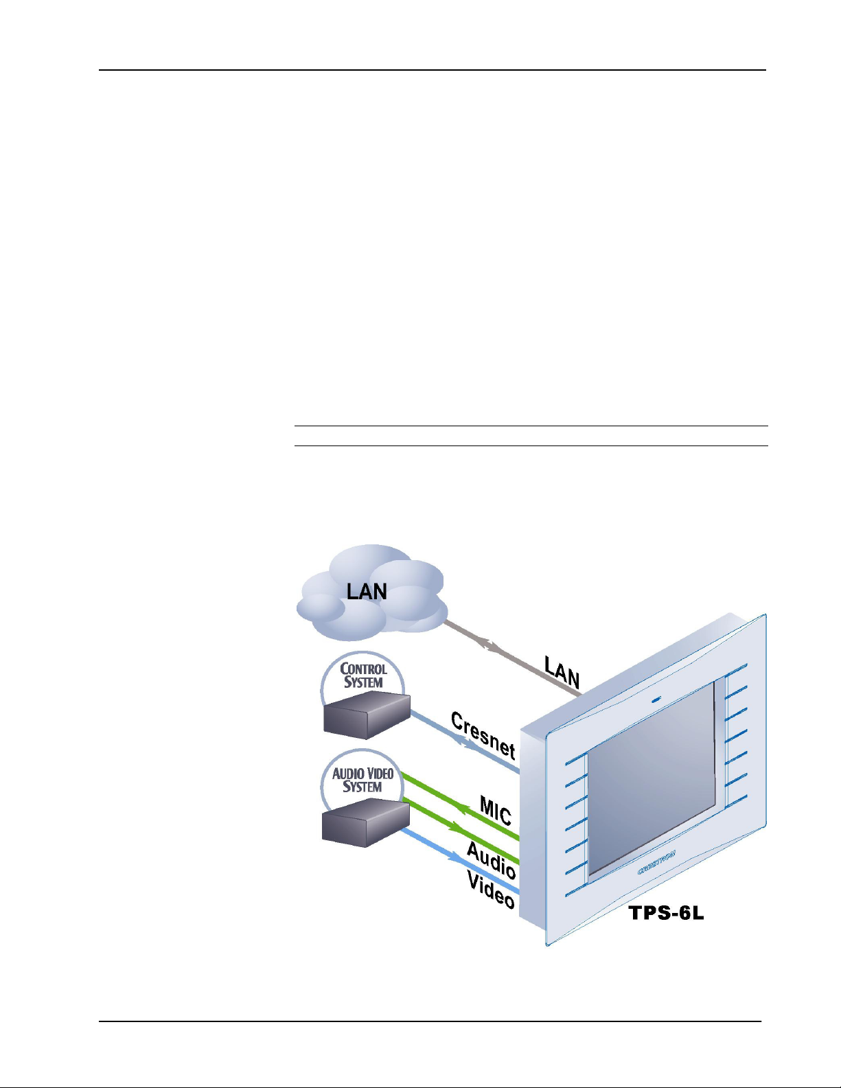
Applications
The following diagram shows a TPS-6L in a basic AV application.
TPS-6L Application Diagram
Operations & Installation Guide – DOC. 6564B Isys® 5.7-inch Wall Mount Touchpanel: TPS-6L • 3
Isys® 5.7-Inch Wall Mount Touchpanel Crestron TPS-6L
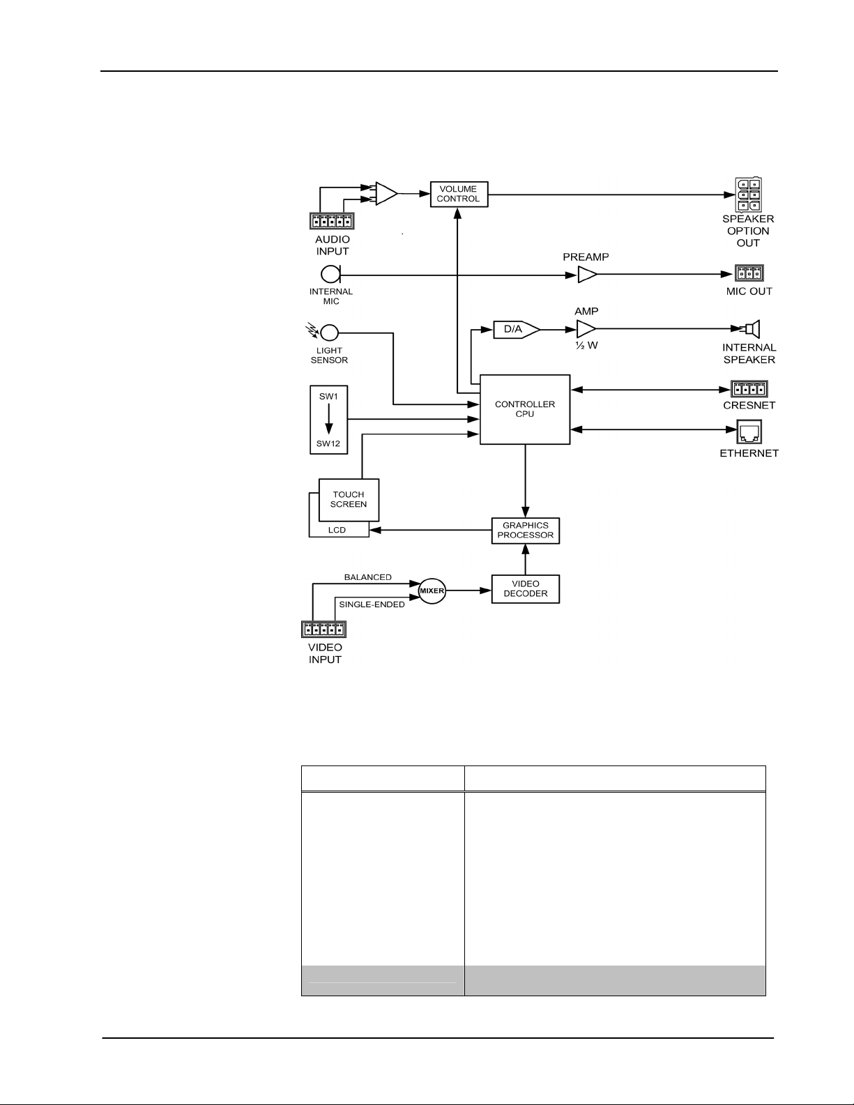
Internal Block Diagram
The following diagram represents the basic operation of the TPS-6L.
TPS-6L Internal Block Diagram
Specifications
Specifications for the TPS-6L are given in the following table.
TPS-6L Specifications
SPECIFICATION DETAILS
Touchscreen Display
Display Type:
Size:
Aspect Ratio:
Resolution:
Brightness:
Contrast:
Color Depth:
Illumination:
Viewing Angle:
Touchscreen:
Light Sensor Programmable photo sensor for automatic backlight
(Continued on the next page)
4 • Isys® 5.7-inch Wall Mount Touchpanel: TPS-6L Operations & Installation Guide - DOC. 6564B
TFT Active matrix color LCD
5.7 inch (14.48 cm) diagonal
4:3 VGA
640 x 480 pixels
350 nits (cd/m
400:1
18-bit, 256k colors
Backlit fluorescent
±80° horizontal, +80°/-70° vertical
Resistive membrane
dimming
2
)
Crestron TPS-6L Isys® 5.7-Inch Wall Mount Touchpanel
TPS-6L Specifications (Continued)
SPECIFICATION DETAILS
Touchpanel Processor
CPU
Touchpanel Memory
SDRAM:
Flash:
Maximum Project Size:
Graphic Engine Isys engine; 16-bit non-palette graphics; 65,536 colors;
Ethernet 10BaseT/100BaseTX, auto-switching, auto-negotiating,
Video
Signal Types:
Formats:
Color Depth:
Windowing:
Audio
Hardware Features:
Audio Feedback (WAV):
Amplification:
Power Requirements
Cresnet Power Usage:
Default Net ID 03
Minimum 2-Series Control
System Update File
Environmental
Temperature:
Humidity:
Enclosure
Construction:
Front Bezel:
Dimensions
Height:
Width:
Depth:
Weight 1 lb, 8.3 oz (10.94 kg)
Available Accessories
TPS-6L-FP
TPS-6L-FP-NB
SPK-6L
1. The panel will not load dynamic graphics if they are located on a password protected HTTP
server.
2. The latest software versions can be obtained from the Crestron website. Refer to the NOTE
following these footnotes.
3. Crestron 2-Series control systems include the AV2 and PRO2. Consult the latest Crestron
Product Catalog for a complete list of 2-Series control systems.
2, 3
32-bit Freescale ColdFire
32 MB
32 MB
28 MB
Synapse image rendering algorithm; multi-mode objects,
dynamic graphics
fps) animation, color key video windowing
full/half duplex, TCP/IP, UDP/IP, CIP, IEEE 802.3U
compliant
Composite
NTSC 480i or PAL 576i
18-bit; 262,144 colors
Single-window, deinterlaced and scalable to full-screen.
Built-in microphone, optional amplified speaker (rear),
internal volume & tone control
8-bit PCM, mono, 8 kHz sampling rate
0.75 Watt for small speaker (WAV/keyclick); 6 Watts for
optional large speaker (line input)
15 Watts (0.625 Amp @ 24 Volts DC)
Version 3.137.CUZ or later
32° to 104°F (0° to 40°C)
10% to 90% RH (non-condensing)
Injection-molded plastic, flush-mountable using (4) clips
provided (additional mounting kits available)
Injection-molded plastic, button and no-button bezels
included, optional solid or backlit engraving sold
separately
5.60 in (14.23 cm)
7.40 in (18.80 cm)
2.28 in (5.78 cm) without external speaker
Engravable Faceplate w/Buttons
Engravable Faceplate w/o Buttons
Speaker Kit
®
Microprocessor
1
, PNG translucency, full-motion (60
NOTE: Crestron software and any files on the website are for Authorized Crestron
dealers and Crestron Authorized Independent Programmers (CAIP) only. New users
Operations & Installation Guide – DOC. 6564B Isys® 5.7-inch Wall Mount Touchpanel: TPS-6L • 5
Isys® 5.7-Inch Wall Mount Touchpanel Crestron TPS-6L
may be required to register to obtain access to certain areas of the site (including the
FTP site).
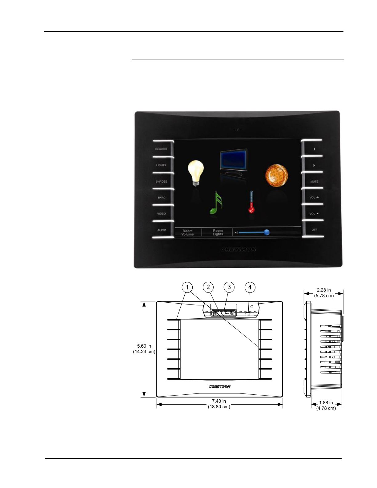
Physical Description
This section provides information on the connections, controls and indicators
available on your TPS-6L.
TPS-6L Physical View (with Button Bezel)
TPS-6L Dimensions – Front and Side View with Cutaway Showing Internal Controls
6 • Isys® 5.7-inch Wall Mount Touchpanel: TPS-6L Operations & Installation Guide - DOC. 6564B

Crestron TPS-6L Isys® 5.7-Inch Wall Mount Touchpanel
TPS-6L Dimensions and Connections – Rear View
TPS-6L Connectors, Controls & Indicators
#
CONNECTORS
1
,
CONTROLS &
INDICATORS
1
Pushbuttons
2 Microphone
3
Light Sensor
4 Reset Pushbutton2
5
(Continued on following page)
(12) Programmable pushbuttons, integral to the
supplied button bezel. A non-pushbutton bezel is
also provided if the buttons are not desired.
Refer to “Optional Pushbuttons” on page 2 for
additional details.
(1) Built-in microphone behind the bezel
supports programmable intercom functionality.
(1) Programmable photosensor behind the
bezel for automatic backlight dimming. Refer to
“Auto Brightness Control” on page 23 for
additional information.
(1) Miniature pushbutton behind the bezel, used
to reset the touchpanel.
(1) 8-wire RJ-45 with two LED indicators;
10BaseT/100BaseTX Ethernet port;
Green LED indicates link status;
Yellow LED indicates Ethernet activity
PIN SIGNAL PIN SIGNAL
DESCRIPTION
1 TX + 5 N/C
2 TX - 6 RC 3 RC+ 7 N/C
4 N/C 8 N/C
Operations & Installation Guide – DOC. 6564B Isys® 5.7-inch Wall Mount Touchpanel: TPS-6L • 7
Isys® 5.7-Inch Wall Mount Touchpanel Crestron TPS-6L
TPS-6L Connectors, Controls & Indicators (Continued)
#
CONNECTORS
CONTROLS &
INDICATORS
1
,
DESCRIPTION
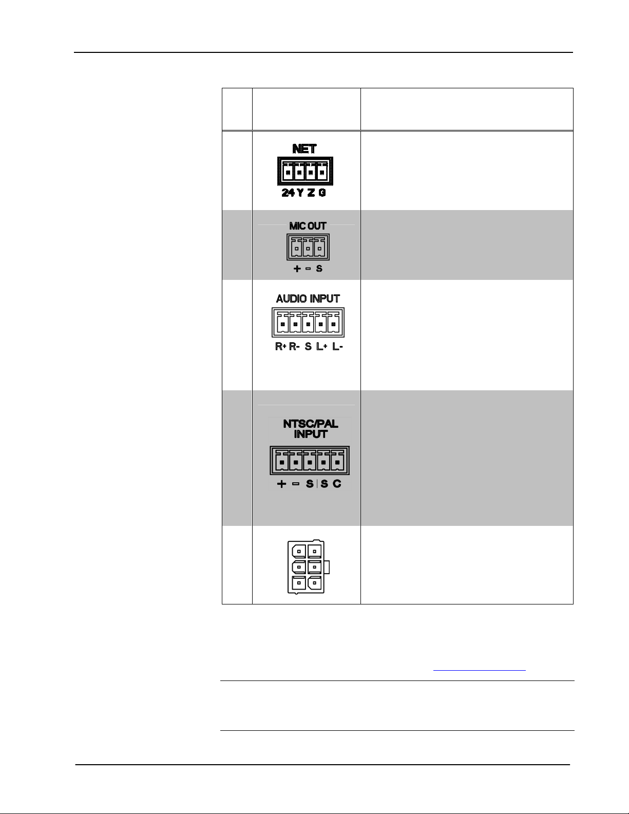
6
(1) Four-position terminal block connector for
data and power. Connects to Cresnet control
network.
Pin 1 (24) Power
Pin 2 (Y) Data
Pin 3 (Z) Data
Pin 4 (G) Ground
7
8
(1) 3-pin 3.5mm detachable terminal block
Balanced mono line-level output
Output Impedance: 600 ohms balanced, 300
ohms unbalanced
Maximum Output Level: 2 V
rms
unbalanced
(1) 5-pin 3.5mm detachable terminal block
Balanced/unbalanced stereo (summed to mono)
line-level input (requires SPK-6L);
Input Impedance: 10k ohms balanced, 5k ohms
unbalanced;
Maximum Input Level: 2 V
balanced/unbalanced;
rms
Normally connects to a Crestron CAT5
balanced audio source via CresCAT cable
balanced, 1 V
3
rms
;
Maximum CAT5 Cable Length: 1000 feet
9
(1) 5-pin 3.5mm detachable terminal block
Balanced (CAT5) or unbalanced (coaxial)
composite video inputs
Formats: NTSC 480i or PAL 576i
Input Impedance: 100 ohms balanced, 75 ohms
unbalanced;
Input Level: 1 V
nominal;
p-p
Balanced input normally connects to a Crestron
CAT5 balanced video source via CresCAT
cable3, using +, -, and S connections.
Unbalanced video uses S and C connections.
Maximum CAT5 Cable Length: 750 feet
10
(1) Six-pin (2x3) rectangular. Connects to
optional external speaker kit (SPK-6L, sold
separately).
1. Interface connectors for NET, MIC OUT, AUDIO INPUT, and the NTSC/PAL INPUT ports are
provided with the unit.
2. To access the reset button, remove the bezel and then use a narrow blunt instrument such as the end of
a ballpoint pen to press the button.
3.
For details on CAT5 wiring, refer to the latest version of the CAT5 Reference Guide (Doc. 6137),
which is available for download from the Crestron website (www.crestron.com/manuals).
CAUTION: Do not attempt to press the reset button by inserting a paperclip or
similar device through the small hole in the bezel. This could cause physical damage
to the microphone or the light sensor, or a short circuit on the printed circuit board
located in that area. Remove bezel to access the reset button.
8 • Isys® 5.7-inch Wall Mount Touchpanel: TPS-6L Operations & Installation Guide - DOC. 6564B

Crestron TPS-6L Isys® 5.7-Inch Wall Mount Touchpanel
Industry Compliance
As of the date of manufacture, the TPS-6L has been tested and found to comply with
specifications for CE marking and standards per EMC and Radiocommunications
Compliance Labelling.
NOTE: This device complies with part 15 of the FCC rules. Operation is subject to
the following two conditions: (1) this device may not cause harmful interference and
(2) this device must accept any interference received, including interference that may
cause undesired operation.
This equipment has been tested and found to comply with the limits for a Class B
digital device, pursuant to part 15 of the FCC Rules. These limits are designed to
provide reasonable protection against harmful interference in a residential
installation. This equipment generates, uses and can radiate radio frequency energy
and if not installed and used in accordance with the instructions, may cause harmful
interference to radio communications. However, there is no guarantee that
interference will not occur in a particular installation. If this equipment does cause
harmful interference to radio or television reception, which can be determined by
turning the equipment off and on, the user is encouraged to try to correct the
interference by one or more of the following measures:
Reorient or relocate the receiving antenna.
Increase the separation between the equipment and receiver.
Connect the equipment into an outlet on a circuit different from that to
which the receiver is connected.
Consult the dealer or an experienced radio/TV technician for help.
Operations & Installation Guide – DOC. 6564B Isys® 5.7-inch Wall Mount Touchpanel: TPS-6L • 9

Isys® 5.7-Inch Wall Mount Touchpanel Crestron TPS-6L
Setup
Network Wiring
When wiring the network, consider the following:
• Use Crestron Certified Wire.
• Use Crestron power supplies for Crestron equipment.
• Provide sufficient power to the system.
CAUTION: Insufficient power can lead to unpredictable results or damage to
the equipment. Please use the Crestron Power Calculator to help calculate how
much power is needed for the system (http://www.crestron.com/calculators
• For larger networks, use a Cresnet Hub/Repeater (CNXHUB) to maintain signal
quality.
For more details, refer to “Check Network Wiring” on page 44.
Ethernet
).
Net ID
IP ID
The TPS-6L also uses high-speed Ethernet for communications between the device
and a control system, computer, digital media server and other IP-based devices.
For information on connecting Ethernet devices in a Crestron system, refer to the
latest version of the Crestron e-Control Reference Guide (Doc. 6052).
Identity Code
The Net ID of the TPS-6L has been factory set to 03. The Net IDs of multiple
TPS-6L devices in the same system must be unique. The Net ID is set using the
internal setup menu (refer to “Interface Menu” on page 13). The Net ID may also be
set from a personal computer (PC) via the Crestron Toolbox™ (refer to “Establishing
Communication” on page 41).
The IP ID is set within the TPS-6L’s table using Crestron Toolbox. For information
on setting an IP table, refer to the Crestron Toolbox help file. The IP IDs of multiple
TPS-6L devices in the same system must be unique.
When setting the IP ID, consider the following:
• The IP ID of each unit must match an IP ID specified in the SIMPL Windows
program.
• Each device using IP to communicate with a control system must have a unique
IP ID.
10 • Isys® 5.7-inch Wall Mount Touchpanel: TPS-6L Operations & Installation Guide - DOC. 6564B
Crestron TPS-6L Isys® 5.7-Inch Wall Mount Touchpanel
Configuring the Touchpanel
NOTE: The only connection required to configure the touchpanel is power. Refer to
“Hardware Hookup” on page 32 for details.
To configure the unit, it may be necessary to access a series of setup screens prior to
viewing run-time screens that are loaded into the touchpanel for normal operation.
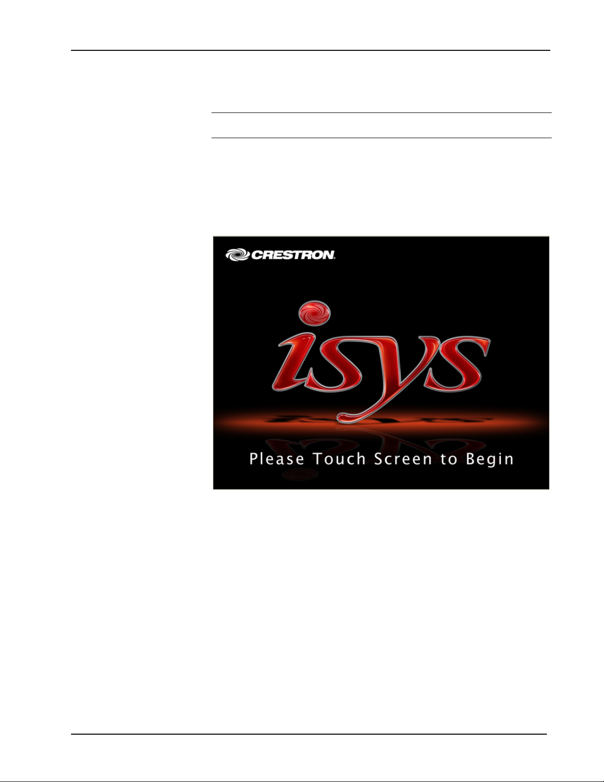
The MAIN MENU for configuring the touchpanel appears when a finger is held to
the touchscreen as power is applied, after the hardware reset button is pressed and
released, or after touching the supplied opening screen. Refer to the following
illustration.
Opening Screen
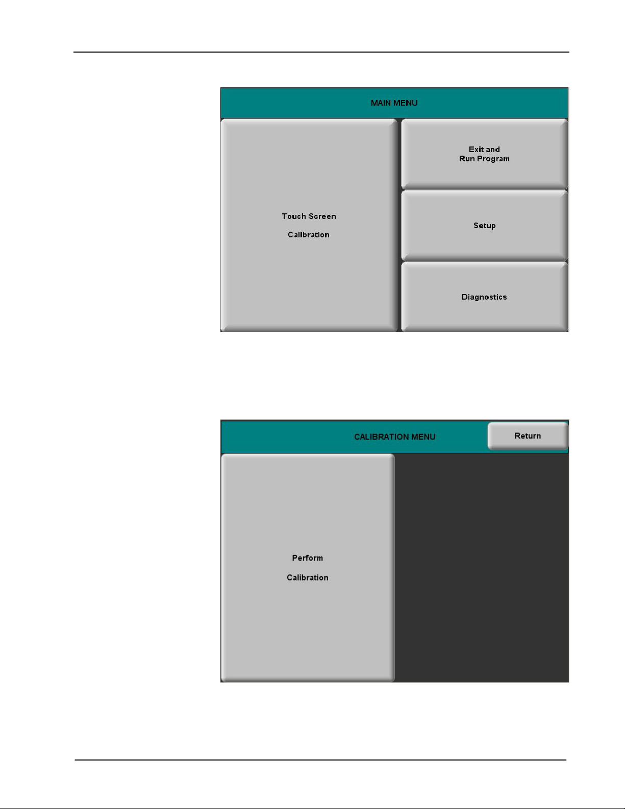
Upon entering Setup Mode, the MAIN MENU, as shown in the following
illustration, displays four buttons: Touch Screen Calibration, Exit and Run
Program, Setup, and Diagnostics.
After all setup procedures are completed, press Exit and Run Program to save the
information to EEPROM and exit Setup Mode.
Operations & Installation Guide – DOC. 6564B Isys® 5.7-inch Wall Mount Touchpanel: TPS-6L • 11
Isys® 5.7-Inch Wall Mount Touchpanel Crestron TPS-6L
MAIN MENU
Calibration Menu
Before beginning other setup procedures, it is advisable to perform screen
calibration. Press Touch Screen Calibration to display the CALIBRATION
MENU, as shown in the following illustration.
CALIBRATION MENU
Touch Perform Calibration. The message “Touch Upper Left” appears centered on
the panel with a cross hair in the upper left corner. Touch the center of the cross hair
in the corner of the screen to initiate calibration. Another message, “Touch Upper
Right”, appears with a cross hair in the correct corner. Touch the center of the cross
12 • Isys® 5.7-inch Wall Mount Touchpanel: TPS-6L Operations & Installation Guide - DOC. 6564B
Crestron TPS-6L Isys® 5.7-Inch Wall Mount Touchpanel
hair in the corner of the screen. A final message, “Touch Lower Right”, appears with
a cross hair in the correct corner. Touch the center of the cross hair in the corner of
the screen to conclude calibration and return to the MAIN MENU.
NOTE: When touching the screen during calibration, be as accurate as possible.
Use the tip of a capped pen or the eraser end of a pencil. To cancel calibration and
return to the MAIN MENU without saving calibration data, create a calibration error
by touching the screen in the same spot three times.
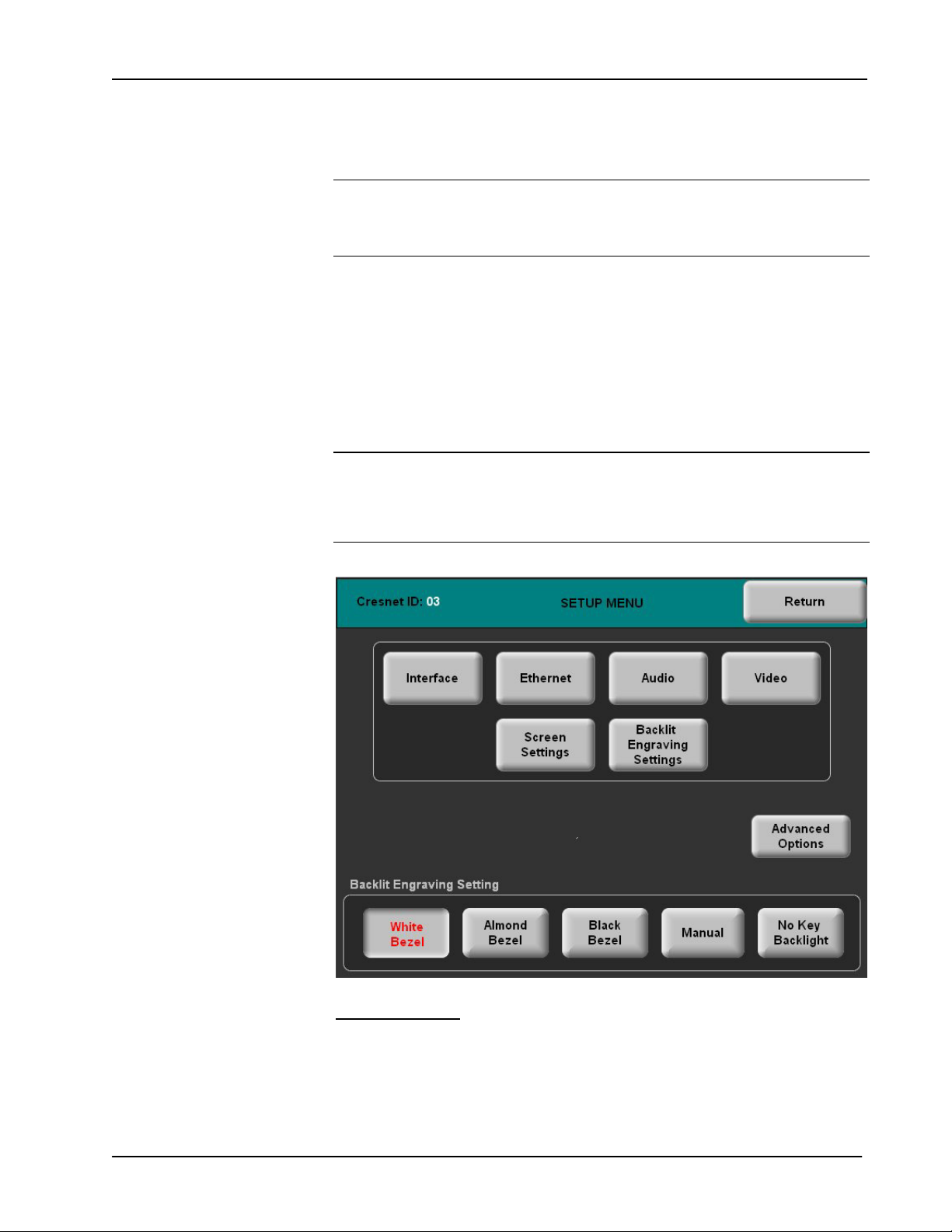
Setup Menu
To obtain the SETUP MENU, press the Setup button from the MAIN MENU. The
SETUP MENU offers a series of buttons that open additional menus and displays,
which are detailed in subsequent paragraphs. The SETUP MENU also provides a
series of buttons at the bottom that permit easy application of the backlit engraving
setting preset values. Refer to “Backlit Engraving Settings” on page 21 for details.
After all setup parameters have been selected, select the Return button to return to
the MAIN MENU.
NOTE: For convenience, the current CRESNET ID setting is displayed in the upper
left corner.
NOTE: All touchpanel settings are automatically saved in non-volatile memory (on
exit from setup).
SETUP MENU
Interface Menu
The touchpanel communicates with a control system to activate commands or to
display feedback from components within the system. The communication interface
must be correctly specified or communication will not occur. To set communication
parameters, select the Interface button located on the SETUP MENU and display
the INTERFACE MENU, shown on the following page.
Operations & Installation Guide – DOC. 6564B Isys® 5.7-inch Wall Mount Touchpanel: TPS-6L • 13
Loading...