


 Loading...
Crestron SIMPL Windows
Primer

This document was prepared and written by the Technical Documentation department at:
Crestron Electronics, Inc.
15 Volvo Drive
Rockleigh, NJ 07647
1-888-CRESTRON
All brand names, product names and trademarks are the property of their respective owners. © 2003 Crestron Electronics, Inc.
Crestron SIMPL Windows |
Software |
Contents
CRESTRON SIMPL WINDOWS.................................................................................. |
1 |
Overview................................................................................................................................... |
1 |
About this Primer....................................................................................................................... |
1 |
Crestron Development Software ............................................................................................ |
2 |
SIMPL Windows ....................................................................................................................... |
2 |
Crestron VisionTools® Pro-e .................................................................................................... |
2 |
DEAL™ for Windows............................................................................................................... |
2 |
Media Manager™ System Builder™......................................................................................... |
3 |
D3 Pro™.................................................................................................................................... |
3 |
Databases................................................................................................................................... |
3 |
Product Catalog CD................................................................................................................... |
3 |
Crestron Control Systems....................................................................................................... |
5 |
Why Program Control Systems?................................................................................................ |
5 |
Elements of a Control System ................................................................................................... |
5 |
Main Processor .......................................................................................................................... |
5 |
Network Control Modules ......................................................................................................... |
6 |
Plug-in Control Cards ................................................................................................................ |
6 |
User Interfaces........................................................................................................................... |
6 |
User devices............................................................................................................................... |
7 |
Control Methods ...................................................................................................................... |
7 |
Relay closures............................................................................................................................ |
7 |
Serial Communications.............................................................................................................. |
8 |
IR (Infrared)............................................................................................................................... |
8 |
Custom Serial .......................................................................................................................... |
10 |
RS-232, RS-422, and RS-485 .................................................................................................. |
10 |
MIDI (Musical Instrument Digital Interface) .......................................................................... |
11 |
Analog Voltages ...................................................................................................................... |
12 |
Custom Crestron Interfaces ..................................................................................................... |
12 |
Cresnet..................................................................................................................................... |
12 |
SIMPL WINDOWS PROGRAMMING........................................................................ |
15 |
Introduction to SIMPL.......................................................................................................... |
15 |
Symbol Categories................................................................................................................... |
15 |
Device Symbols....................................................................................................................... |
15 |
Logic Symbols......................................................................................................................... |
16 |
Symbol Properties.................................................................................................................... |
16 |
Inputs ....................................................................................................................................... |
16 |
Outputs..................................................................................................................................... |
16 |
Parameters ............................................................................................................................... |
16 |
Signal Types ............................................................................................................................ |
17 |
Digital Signals ......................................................................................................................... |
18 |
Analog Signals......................................................................................................................... |
18 |
Primer – DOC. 6253 |
Contents • i |

Software |
Crestron SIMPL Windows |
Serial Signals ........................................................................................................................... |
18 |
Special Signals ‘0’ and ‘1’....................................................................................................... |
19 |
Logic Waves and Logic Solutions ........................................................................................... |
19 |
Programming with User Interfaces...................................................................................... |
20 |
Button Presses.......................................................................................................................... |
20 |
Button Feedback ...................................................................................................................... |
21 |
Subpages (touchpanels only) ................................................................................................... |
22 |
Analog displays (touchpanels only)......................................................................................... |
23 |
Indirect text (touchpanels only) ............................................................................................... |
23 |
Building a Program with SIMPL Windows ........................................................................ |
24 |
Programming Process .............................................................................................................. |
24 |
Basic Programming Rules ....................................................................................................... |
24 |
Build a System......................................................................................................................... |
24 |
Control Systems....................................................................................................................... |
26 |
Network Hardware................................................................................................................... |
27 |
Plug-in Control Cards .............................................................................................................. |
28 |
Serial Devices .......................................................................................................................... |
29 |
User Devices............................................................................................................................ |
29 |
Network IDs ............................................................................................................................ |
30 |
Configure Devices ................................................................................................................... |
30 |
Cresnet Devices ....................................................................................................................... |
30 |
Ethernet Devices...................................................................................................................... |
32 |
Serial Devices .......................................................................................................................... |
33 |
Touchpanels............................................................................................................................. |
33 |
Connecting Signals .................................................................................................................. |
34 |
Define Signals from User Interface ......................................................................................... |
34 |
Using Logic Symbols .............................................................................................................. |
36 |
PROGRAMMING WITH LOGIC SYMBOLS ............................................................. |
37 |
Introduction ........................................................................................................................... |
37 |
Types of Logic Symbols......................................................................................................... |
37 |
Basic Logic.............................................................................................................................. |
38 |
NOT Symbol............................................................................................................................ |
38 |
NOT Symbol Example: Automatic Camera Control ............................................................... |
39 |
OR Symbol .............................................................................................................................. |
39 |
OR Symbol Example: Volume Un-mute ................................................................................. |
39 |
AND Symbol ........................................................................................................................... |
40 |
AND Symbol Example: discrete power on/off ........................................................................ |
40 |
Buffer Symbol ......................................................................................................................... |
41 |
Buffer Example: multi-device control ..................................................................................... |
42 |
Buffer Example: triggering multiple events............................................................................. |
43 |
State Logic .............................................................................................................................. |
46 |
Set/Reset Latch symbol ........................................................................................................... |
47 |
Set/Reset Latch Example: System Power Relay...................................................................... |
47 |
Toggle Symbol......................................................................................................................... |
47 |
Toggle Example: Volume Mute............................................................................................... |
48 |
Toggle Example: Device Power On/Off.................................................................................. |
48 |
Interlock Symbol ..................................................................................................................... |
49 |
Interlock Example: Source Selection Feedback....................................................................... |
49 |
ii • Contents |
Primer – DOC. 6253 |

Crestron SIMPL Windows |
Software |
Time-based Logic................................................................................................................... |
52 |
One Shot Family...................................................................................................................... |
52 |
One Shot .................................................................................................................................. |
52 |
Multiple One Shot.................................................................................................................... |
53 |
Retriggerable One Shot............................................................................................................ |
53 |
Delay Symbol .......................................................................................................................... |
54 |
Oscillator Symbol .................................................................................................................... |
55 |
Analog Logic .......................................................................................................................... |
57 |
Analog Ramp Symbol.............................................................................................................. |
57 |
Analog Initialize ...................................................................................................................... |
58 |
Analog Preset Symbol ............................................................................................................. |
60 |
Serial/Analog One-Shot........................................................................................................... |
61 |
Modules ................................................................................................................................... |
63 |
Communication Settings.......................................................................................................... |
63 |
Compiling and Uploading Programs ....................................................................................... |
65 |
Software License Agreement ................................................................................................ |
67 |
Return and Warranty Policies.............................................................................................. |
69 |
Merchandise Returns / Repair Service..................................................................................... |
69 |
CRESTRON Limited Warranty............................................................................................... |
69 |
Primer – DOC. 6253 |
Contents • iii |
Crestron SIMPL Windows |
Software |
Crestron SIMPL Windows
Overview
About this Primer
The intent of this primer is to introduce programmers to SIMPL Windows programming techniques and how they apply to Crestron control systems. This includes an understanding of how control systems use touchpanels and button panels as user interfaces. Through these interfaces, a user might send a signal that is processed by the control system (manipulated by logic symbols) and outputted to eventually control a device.
Simplified Control System
The control process is more complex than this and has many more variables. However, this is the basic concept of programming Crestron control systems. Users of this information should have a basic understanding of the following:
Microsoft Windows
•Knowledge of basic Windows commands
•Familiarity with Windows features and functions
Audio/Visual
•Knowledge of different control formats (serial, IR, relays)
•Familiarity with A/V equipment
•Ability to read and understand control and wiring diagrams
SIMPL Windows provides a wide variety of symbols that are constantly being expanded to support virtually every possible application. As you become proficient at using SIMPL Windows it will become obvious that there are many ways to solve the same control problem. This allows for programming creativity and independent flexibility.
Primer – DOC. 6253 |
Crestron SIMPL Windows • 1 |

Software |
Crestron SIMPL Windows |
Crestron Development Software
SIMPL Windows
Crestron SIMPL Windows provides all the tools necessary to configure, program, test and debug an integrated control system application. Combining the familiar drag-and-drop functionality of Microsoft Windows with the programming power of SIMPL (Symbol Intensive Master Programming Language), SIMPL Windows provides the link between Crestron systems hardware, user interfaces, and the world of equipment to be controlled.
The configuration aspect of SIMPL Windows allows you to select the control system, user interfaces, network devices and controlled equipment required for the installation. To these hardware components you can assign port addresses, Network IDs and IP addresses, set communication parameters and specify which device is connected to which card or network control module. You can also specify what VisionTools™ Pro-e touchpanel projects are required for the system.
The programming aspect allows you to select the logic symbols the system will require, assign signals to those symbols and connect the signals to other symbols or devices as determined by the program logic. SIMPL Windows includes a wide variety of symbols that are constantly being expanded to support virtually every possible application. As you become proficient at using SIMPL Windows it will become obvious that there are many ways to solve the same control problem. This allows for programming creativity and independent flexibility.
Finally, the testing aspect allows you to test and debug your SIMPL Windows program using powerful diagnostic tools including Test Manager, Network Analyzer, and the Crestron Viewport. You can call these tools directly from SIMPL Windows or launch the tools independently.
For even greater flexibility, the SIMPL Windows installation package includes SIMPL+™, a development tool that allows advanced programmers to create and compile custom control modules using a procedural language similar to C. You can add SIMPL+ modules to your SIMPL Windows program or user module much like a logic symbol, to extend functionality or solve a specific control problem.
SIMPL Windows is fully integrated with Crestron's suite of software tools, which include the following:
Crestron VisionTools® Pro-e
VisionTools® Pro-e is Crestron's touchpanel page design software. Using VisionTools Pro-e, programmers can create powerful touchscreen control interfaces that include pop-up subpages for specific device transport controls, multi-mode buttons and sliders with 3D effects, high-resolution graphics, dynamic text, video windows, sound, and more. VisionTools Pro-e uses join numbers to identify button presses, feedback, and other digital, analog and serial signals. These join numbers correspond to inputs and outputs on the touchpanel symbol detail in SIMPL Windows.
DEAL™ for Windows
Crestron's DEAL™ (Device Editor and Learner) for Windows software enables programmers to learn manufacturer's IR signals. When used in conjunction with the Crestron CNXLIR (IR Learner), DEAL allows you to create, modify and test IR driver files, and to save the learned IR files in the User Database where you can add them to your SIMPL Windows program.
2 • Crestron SIMPL Windows |
Primer – DOC. 6253 |
Crestron SIMPL Windows |
Software |
Media Manager™ System Builder™
The Media Manager™ System Builder™ offers automatic programming for such residential and commercial applications as audio distribution, home theater, and video conferencing. The System Builder provides a Wizard-like interface that takes you through a series of programming screens. Simply follow the prompts to select the control system, user interfaces, devices and functionality. The System Builder then automatically programs, compiles, and uploads the system, including VisionTools Pro-e touchpanel projects and control system logic.
D3 Pro™
Crestron D3 Pro™ software offers design, development, and documentation for a complete residential lighting system, with additional support for auxiliary devices such as security systems, motion detectors and shades. Like the System Builder, D3 Pro presents a Wizard-like interface. Programming is accomplished through a series of simple but powerful System View screens. After the design is complete, D3 Pro automatically creates, compiles, and uploads the control system program and touchpanel projects.
These are just some of the software tools that Crestron has created to help you accomplish your programming tasks more easily and efficiently. You can download all Crestron software for free from the Software Updates area of the Crestron Web site (requires registration).
Databases
The Crestron Database is a large collection of information that is accessed by various Crestron software packages, including SIMPL Windows, D3 Pro, and the System Builder. The bulk of the Database consists of IR driver files that control user devices such as CD players, DVD players, conferencing equipment, and other thirdparty IR devices the end user interfaces with using the Crestron control system.
In addition to IR driver files, the Crestron Database contains hundreds of Crestron logic modules that control third-party device functions. Modules are self-contained logic programs that have been pre-coded, tested and debugged at Crestron. These dedicated modules can be plugged into a program and used to generate all the proper control codes for a device automatically.
The User Database is designed to store IR driver files that are not included in the Crestron Database. Programmers usually generate IR files using the Crestron CNXLIR (IR Learner) in conjunction with DEAL (Driver Editor and Learner) for Windows software. Alternatively, you can obtain user IR files by downloading them from the Crestron Design Center or Crestron FTP site.
In addition to IR driver files, the User Modules directory stores user-created logic modules that are not included in the Crestron Database.
Product Catalog CD
Crestron provides a variety of ways for you to obtain information about Crestron hardware. The most comprehensive resource is the Crestron Web site: www.crestron.com. Here you can download the most up-to-date user manuals, reference guides, and CAD drawings for all Crestron control systems, network devices and touchpanels. You can also access the Crestron Design Center, which provides extensive information about user modules that control equipment from I2P partner manufacturers, including help files, sample logic programs, touchpanel projects, cable diagrams, and more.
Primer – DOC. 6253 |
Crestron SIMPL Windows • 3 |
Software |
Crestron SIMPL Windows |
You can access the Crestron Web site directly from the SIMPL Windows Online Support menu. Click Crestron Online for the Crestron home page, or click Crestron Design Center to open the Dealer/Tech Resources page.
The Crestron Product Catalog and Technical Reference CD is another valuable tool that you can use in conjunction with the Crestron Web site, or any time you're not connected to the Internet. The CD is a comprehensive library of Crestron brochures, catalogs, product specification sheets, CAD drawings and user manuals. You can browse the CD independent of any Crestron program, or you can link the CD directly to SIMPL Windows to display documentation for devices you select in the Device Library.
To access user manuals from SIMPL Windows
1.Insert the Product Catalog CD into the CD-ROM drive (you can close the selection screen if it opens automatically).
2.In the SIMPL Windows Device Library, select whichever Crestron control system, network device, touchpanel or control card you want documentation for and press F1.
3.The first time you try to access the Product Catalog CD from SIMPL Windows you will be prompted to browse for the CD-ROM drive or folder where the CD is located. Locate the drive or folder and click Open.
4.If documentation is available for the selected device, SIMPL Windows will find the PDF file and open it in Adobe Reader. If no PDF file is available for the device, then the SIMPL Windows help file will display programming help for the device.
5.You can click Product Catalog CD on the SIMPL Windows Help menu any time you want to open the CD selection screen for documents, brochures, CAD drawings, or utilities.
6.If you do not have the CD inserted and you press F1 on a device in the Device Library, SIMPL Windows will prompt you to insert the CD. You can then either insert the CD or click Cancel to view the online help file.
4 • Crestron SIMPL Windows |
Primer – DOC. 6253 |
Crestron SIMPL Windows |
Software |
Crestron Control Systems
Why Program Control Systems?
The term program refers to the instructions loaded into the control processor that cause it to operate in an intended way. For example, to control a DVD player, you must write a program that tells the control system which port the unit is connected to, what IR codes to send to it, and which buttons on a touchpanel trigger those functions. A typical program may contain hundreds of similar instructions designed to allow control of an entire rack full of audio/visual equipment. All programs are written in the SIMPL programming language. Crestron has created the SIMPL Windows development application expressly for writing in this language.
Elements of a Control System
Main Processor
The Crestron control system processor is the heart of a complete remote control system. Its basic function is to integrate and communicate with equipment made by other manufacturers. To do this the control system’s working memory (RAM) must be programmed to use the specific instructions, or program, to communicate with the devices being controlled.
In addition to working memory, control systems contain an operating system (OPS). Similar to the operating systems that run personal computers, the OPS is a set of instructions that enables the control system to understand the program that has been loaded into it and to control equipment connected to the system by various input/output devices (an infrared module, for example).
The need to upgrade the OPS will arise if programmers want to take advantage of new programming capabilities, new Crestron hardware devices, or to correct a problem found in a previous version. You can download control system updates from the Crestron Web site. Operating system files on this site have file names such as c2.v3080.cuz, with different extensions depending on the type of processor. Before downloading, make sure the update is compatible with your control system by verifying that the file name matches the OPS version number and the extension corresponds to your control processor model.
2-Series processors use a CUZ file to load the operating system to the control system. 2-Series processors provide 32 MB of DRAM, which is expandable to 4GB for processors that include a Compact Flash slot. The size of the program, and number of analog, digital, and serial signals that can be processed are limited only by the amount of available RAM. In addition to RAM, the processor provides 256KB of NVRAM (non-volatile RAM) that is used to store SIMPL+ variables and variables expressly written to it by some “memory” symbols in SIMPL. These symbols include Analog RAM, Digital RAM, and Analog Non-Volatile Ramp, and are commonly used for lighting or volume presets. Non-volatile RAM retains data written to it when power is turned off. The 256K of NVRAM may also be split to use 64K or 128K as an NVRAM disk.
X-Series processors have a base Monitor in addition to the operating system, as well as separate TCP/IP stacks, all contained in a UPZ file. The separate stacks are for systems that include the CNXENET or CNXENET+ card for Ethernet communication. X-Series processors allow a total of 16373 user-defined digital
Primer – DOC. 6253 |
Crestron SIMPL Windows • 5 |

Software |
Crestron SIMPL Windows |
signals, and 2048 user-defined analog/serial signals. The processor also provides 256K of NVRAM that is divided in different ways depending on the type of Ethernet card being used.
“Legacy” control processors such as the ST-CP and CN-Series processors allow a total of 4085 user-defined digital signals and 512 analog/serial user-defined signals.
Processor
2-Series
X-Series
ST-CP and CN-Series
Maximum number of signals
Depends on available RAM
16373 digital
2048 analog/serial
4085 digital
512 analog/serial
Network Control Modules
Network control modules are devices connected to the Cresnet or Ethernet network that extend the functionality of the control system and allow it to control third-party equipment. Crestron provides an impressive variety of network control modules, including audio receivers, mixers, distribution switchers, surround sound processors, video processors, camera controllers and room solution boxes.
Any 2-Series processor is also capable of operating in “slave” mode, meaning that it can be controlled by another 2-Series processor, in order to operate as a powerful network control module.
Network control modules are located in the SIMPL Windows Device Library as
Cresnet Control Modules and Ethernet Control Modules. Lighting control modules are located in the Lighting folder.
Plug-in Control Cards
Crestron plug-in control cards are circuit boards that can be easily installed in the expansion slots of a processor and allow it to communicate with equipment. Plug-in control cards include network interface cards that connect the 2-Series or X-Series control system to the Ethernet network. Control cards are represented in the SIMPL Windows Device Library as Plug-in Control Cards. Once installed and configured the control cards allow the system to control virtually any number and variety of devices.
Many control devices such as serial ports are available as either Plug-in Control Cards or Network Control Modules.
Cards are usually less expensive since they don’t require housing or power regulation. Of course, control cards are limited to the number of expansion slots in the control processor.
User Interfaces
User interfaces are the controls that the user will use to request an action. Crestron manufacturers a large variety of user interfaces, ranging from simple and inexpensive handheld remotes and keypads to top-of-the-line touchpanels.
6 • Crestron SIMPL Windows |
Primer – DOC. 6253 |

Crestron SIMPL Windows |
Software |
Touchpanels
Crestron touchpanels are the most common user interface of any control system. Touchpanels are available in Cresnet, Ethernet, and wireless versions with either gray scale or color displays.
Programmers develop touchpanel screen layouts with VisionTools Pro-e software. Buttons are assigned numbers that link them to the specific operation that it represents in the SIMPL Windows program. These links are called join numbers and will be describe in more detail later.
Wired Keypads
Wired keypads have a simple design and operate on the Cresnet network. Their push-button operation offers classic styling. Many models offer a choice of button configurations and panel finishes.
Wireless Remotes
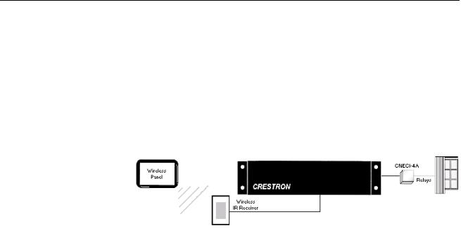
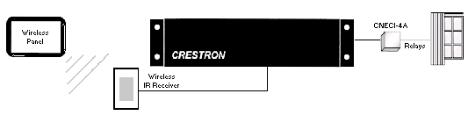
Crestron wireless touchpanels and remotes communicate with the control system using Crestron gateway receivers (e.g. CNRFGWA, CNIRGWA, or CNRFGWX). The gateway is connected to the control system via Cresnet. Wireless IR/RF transmitters are one-way devices; they do not receive, but only transmit IR or RF signals. Likewise, the Crestron CNIRGW is a one-way remote IR receiver and the CNRFGWA is a one-way remote RF receiver.
User devices
User devices are the audio/visual equipment, such as CD players, TVs, and VCRs that will be controlled by the Crestron control system. The User Devices folder contains hundreds of driver files for these devices, organized by manufacturer or device type.
Control Methods
When working with and programming Crestron control systems, it is important to have a good understanding of how devices can be controlled. In general, any device that has an electrical interface of some sort can be controlled by a Crestron control system. The most common control methods are listed below:
•Relay closures (mechanical or solid-state)
•Serial communications
•Analog voltages
•Custom Crestron interfaces
Relay closures
Many devices employ internal electronics that allow functions to be triggered through a simple electrical contact. In the world of control systems, this is accomplished using relays. Devices such as screens and drapes, or third-party lighting control systems tend to use this type of interface. In addition, some notdimmed lighting circuits can be switched on and off using relays. Crestron manufactures relays of many different flavors: low-power relays for use with devices that do not draw a lot of current or require high voltages, and high-power relays for
Primer – DOC. 6253 |
Crestron SIMPL Windows • 7 |
Software |
Crestron SIMPL Windows |
direct control of motors and lighting circuits. In addition, relays can either be mechanical or solid-state. If you are unsure about what type of relay is needed for a given application, you can call Crestron technical support for assistance.
Serial Communications
Many devices today can be controlled using various types of serial communication. Typically serial-controlled devices use one of the following types of serial communication: Infrared, RS-232, RS-422, RS-485, MIDI, and "custom serial". In the next few paragraphs we will discuss the differences between these formats.
What does "serial" mean?
The term serial describes a communications format in which one piece of information is transmitted and/or received after the next. As an analogy, think of a telephone where you hear one word after word until a sentence is constructed. This is different from parallel communications in which multiple pieces of information are transmitted and received simultaneously.
Serial communication encompasses a wide variety of popular formats, many of which are supported directly with Crestron control systems. The sections below describe the most common formats in more detail.
IR (Infrared)
For many years infrared remote control has been very popular, and today it remains among the most common forms of serial control. As the name implies, infrared control consists of serial data transmitted via pulses of infrared light. In addition, IR signals are usually modulated by a carrier signal. In most cases this carrier signal has a frequency of approximately 40kHz, though some can go as high as 1MHz.
In the Crestron world there are two applications of IR control. Crestron wireless user interfaces may use IR for communication with the control system. In this case the IR is transmitted/received by Crestron equipment is in a proprietary format.
Crestron IR wireless interface
The other application of IR control is IR signals that the system generates to control other manufacturer’s devices (e.g. to mimic Sony or Panasonic). The system can generate the functions that were available on the device's remote control.
Since IR is a one-way communication, there is no feedback from the equipment being controlled. That is, data is transmitted to the device to be controlled, but no data is returned from the device to the control system. This means that when using IR control, you have no true feedback from the device telling you that your command was accepted, for example. This is one inherent disadvantage with this type of control. Another disadvantage of IR is that it depends upon a line-of-sight between the control system and the device to be controlled. To counter this problem, Crestron can provide an IR probe, which provides a wired connection from the
8 • Crestron SIMPL Windows |
Primer – DOC. 6253 |
Crestron SIMPL Windows |
Software |
control system to the IR receiver on the controlled device. Care must be taken to ensure that the IR emitter on the IR probe is properly located next to the receiver.
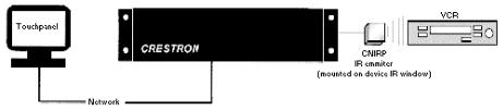
Remote IR Equipment
Manufacturers do not normally publish the exact nature of the data that is being sent via their IR remote controls. Therefore in order to generate the proper signal out of the Crestron IR card, the remote must be learned through the use of a special device called an IR Learner. The device, when attached to a PC and used in conjunction with Crestron’s IR learning software (DEAL for Windows), will generate a driver file that can be inserted into your programs. Once the program is finished and loaded into the control system, the control system’s IR card can convert the information in the driver file into the proper electrical signal.
Crestron IR Equipment
IR Probes (CNXIRP and STIRP)
The IR probe (CNXIRP or STIRP) is a very small, wired IR emitter that Crestron developed to be installed externally over a device’s IR window. The probe is wired from the control system and emits IR signals directly into the device's IR window. Since the IR Probe can be mounted externally on equipment, it eliminates the need to open other manufacturer’s equipment in order to rewire or alter the IR window. In addition, by installing the probe directly on the device being controlled, the interference caused by direct sunlight and high efficiency fluorescent lighting can be eliminated.
IR Sprayer
The IR sprayer in an IR emitter that can “spray” IR signals 90 degrees. It eliminates the need for the IR probe and can be positioned in a central location to reach all devices. It is designed to handle several IR codes so only one sprayer is needed for many devices.
IR Device Modules/Control Cards
IR device modules, such as the C2IR-8 or the IR ports built into some control systems, provide control of IR or some serial controlled devices. The C2IR-8 and the built in IR ports require the IR probe (CNXIRP) when using IR communication.
See Serial IR for information on using IR ports for serial communication.
IR Learner (CNXLIR)
Crestron Electronics CNXLIR is used to "learn" the codes (pulses of infrared light) that a device's remote sends to control a piece of equipment. By learning these codes programmers can create custom IR device drivers. DEAL for Windows software allows programmers to create, modify, and test driver files. Programmers can then store the learned .IR files in the User Database for use in their SIMPL Windows programs.
Primer – DOC. 6253 |
Crestron SIMPL Windows • 9 |
Software |
Crestron SIMPL Windows |
Crestron Database
As described earlier, the Crestron Database contains hundreds of pre-coded IR driver files for programmers to utilize. This database covers most of the IR controlled devices on the market today. In fact, the database supports all current control formats, including relay control, analog voltages, and TCP/IP. Programmers can search the database by manufacturer or device type.
Custom Serial
The term custom serial is used here to describe a communications protocol that is similar to IR, but is carried out over a wire rather than light pulses, and there is no carrier frequency. It is called custom because currently a number of manufacturers employ this method, but there is no true standard. Sony Control-S and Marantz RC-5 are examples of custom serial formats in use today.
In terms of usage, this form of serial communications differs from IR only in that a specially made wired cable must be used in place of an IR probe to connect from the control system to the controlled device. Because the data format is normally identical to a corresponding IR remote, serial drivers are created first by learning the remote to generate an IR driver, then by passing the file through a special filter that removes the carrier frequency. Just like with IR, custom serial signals are generated using an IR card such as the C2IR-8.
Crestron Custom Serial Equipment CNSP-109
The CNS-109 is an Electrahome/Vidikron Cable for use with C2IR-8 or (1) serial output port.
CNSP-110
The CNSP-110 is a Sony VO 5000, 7000, 9000 serial Umatic cable for use with C2IR-8 port.
CNSP-112
The CNSP-112 is a Sony Control-S cable for use with (1) C2IR-8 port.
RS-232, RS-422, and RS-485
The terms RS-232, RS-422, and RS-485 all refer to physical standards for serial communication developed by the Electronic Industries Association (EIA). The standards specify the electrical interface between equipment. These standards have been developed to allow various pieces of equipment to communicate with one another without concern for special hardware; any device that conforms to one of the standards above should be able to communicate with any other device conforming to the same standard. Of the three formats, RS-232 is by far the most popular for use in control systems. For the remainder of this section, the term RS-232 will be used to describe any of the three protocols, except where noted.
Unlike the IR or custom serial formats, RS-232 control does not use ready-to-go driver files. Instead, the data format, or protocol, that a controlled device is expecting will be described in the unit's manual. This protocol includes the data that the device expects to receive and transmit, the speed at which it communicates (baud rate), the error checking (parity), the number of data bits and the number of stop bits. In addition, a given device may require hardware (RTS/CTS) or software (XON/XOFF) handshaking, which controls the flow of data between two devices. All of these elements are adjusted in the control program to match the manufacturer's specification.
10 • Crestron SIMPL Windows |
Primer – DOC. 6253 |

Crestron SIMPL Windows |
Software |
Because of the absence of a driver file, RS-232 control is generally considered more difficult to program than IR or custom serial. This is because each time an RS-232 device is to be programmed, the programmer must look up the protocol in the manual, and then write the necessary logic into his program to send this data. To counter this, many devices have dedicated modules written for them. These modules can be plugged into a program and used to generate all the proper control codes automatically.
The differences between RS-232, RS-422, and RS-485 are physical in nature, and do not affect the programmer, except that they must make sure that the Crestron product being used to send the data supports the format, and has been configured properly.
RS-232 uses one wire to transmit data, and one wire to receive it. It is generally valid for sending data up to 50 feet, but this distance can depend on many factors, such as cable quality, baud rate, and the ambient electrical noise. The RS-422 format uses a balanced pair of wires for transmission, and another pair for reception. The balanced pair allows the data to be less susceptible to noise, and RS-422 signals can be sent up to 2000 feet. The final standard, RS-485, is similar to RS-422 except that a single pair of conductors is used for both transmitting and receiving data. This makes RS485 very attractive for network applications, where data is being shared between more than 2 devices. A typical application might be an HVAC system that communicates to various thermostats and to a control system over an RS-485 LAN.
The Crestron C2IR-8 plug-in control card can only transmit RS-232 one-way. The C2COM-2 plug-in control card is capable of generating RS-232, RS-422 or RS-485 two-way signals. The ST-COM network device can generate RS-232, RS-422, or RS-485 two-way communication data.
Crestron RS-232, RS-422, and RS-485 Equipment C2IR-8
The C2-IR8 includes eight serial ports for one-way RS-232.
C2COM-2
The C2COM-2 is a Cresnet plug-in control card. It includes two bi-directional RS- 232/RS-422 (DB-9) ports with hardware handshaking.
CAUTION: The DB9 pin-outs on the C2COM-2 control card are not standard RS232. Connecting a straight-through serial cable may damage equipment. Refer to the Crestron Cable database or contact Crestron for serial cable pin-out specifications.
ST-COM
The ST-COM network device can generate either RS-232, RS-422, or RS-485 data.
Limitations
RS-232 is limited to a wire length of 50ft (15 m) and a minimum of three conductors (RXD, TXD, and Ground).
Each piece of equipment requires a specific (protocol) format for the data it is expecting.
Programmer needs to be familiar with binary, hex, and/or ASCII in order to generate the correct strings.
MIDI (Musical Instrument Digital Interface)
MIDI stands for Musical Instrument Digital Interface and is yet another serial communications standard. As its name implies, MIDI is used most commonly for allowing musical instruments to talk to one another. However, certain audio mixers,
Primer – DOC. 6253 |
Crestron SIMPL Windows • 11 |
Software |
Crestron SIMPL Windows |
which sometimes find their way into control system applications, use MIDI control. From a programmer’s viewpoint, MIDI does not differ from RS-232, RS-422, or RS485. From a hardware standpoint, the CNX-MIDI card is required to generate the proper control signals.
Crestron MIDI Equipment CNX-MIDI
The CNX-MIDI interface card is a MIDI IN, OUT and THRU interface. It is used with mixers and lighting equipment.
Analog Voltages
Certain devices, typically units such as camera pan-tilt heads, lighting control systems, or voltage-controlled attenuators (VCAs) can be controlled with an analog voltage. Programmable analog voltages can be generated using the CNXAO-8 card or C2I-IO8. The latter card contains 8 Versiports capable of being programmed for digital input/output or analog output.
Custom Crestron Interfaces
Certain devices have control interfaces that do not fall neatly into one control method or category. In these instances Crestron has developed custom modules (either plugin control cards or network modules) to offer control. Examples of these include:
•Line-level audio attenuation (volume control)
•Pan/Tilt and Zoom/Focus control
•Slide projector control
•Keyboard/Mouse interface
•Lighting (dimmed and non-dimmed) and motor control modules
For detailed information regarding the above, see the Crestron Catalog for exact model names, and reference the User Guide for each module.
Cresnet
The Crestron network, or Cresnet, refers to the network topology that is used by Crestron. The RS-485 bus is used to connect the control system to Crestron ‘network’ devices such as a CNECI-4A (electric control interface for AC powered devices) or a CNSC-1A (slide projector interface). The RS-485 bus should be used to locate devices remotely when the limitations of IR and RS 232 restrict the installation plans. For example, IR must have line-of-sight to the device being controlled. Serial communications (RS-232) is limited to 50ft. The Cresnet RS-485 is a proprietary cable connection that can be connected to devices with up to 5,000 feet of cable.
Cresnet cable consists of:
•Pair A #22 AWG, twisted pair with shield for data lines
•Pair B #18 AWG, twisted pair for power and ground
•PVC jacket
12 • Crestron SIMPL Windows |
Primer – DOC. 6253 |

Crestron SIMPL Windows |
Software |
Cresnet - Network Interconnect Specifications
CAUTION: POSSIBLE EQUIPMENT DAMAGE IF MISWIRED.
Do not power up system until all wiring is verified. Care should be taken to ensure data (Y, Z) and power (24, G) connections are not crossed.
Ground shield at control system end only.
Model CNTBLOCK network terminal block is recommended for testing purposes and convenience of wiring.
Primer – DOC. 6253 |
Crestron SIMPL Windows • 13 |
Crestron SIMPL Windows |
Software |
SIMPL Windows Programming
Introduction to SIMPL
Crestron engineers are dedicated to the development of our products and the interface with other manufacturer’s equipment. However, control systems need individual programming in order to be customized for each installation. Crestron control systems are programmed using SIMPL (Symbol Intensive Master Programming Language).
SIMPL is an object oriented programming language designed for easy implementation of your control system requirements. The objects that are used in SIMPL are called symbols. Each symbol has a specific set of operations that it will perform. The lines that connect symbols are called signals. The collection of SIMPL symbols and their interconnection to one another is the program. Therefore, the program is actually a picture created with objects (symbols) and lines (signals). This type of picture is also referred to as a block diagram or flow diagram in other applications. When planning an A/V installation, a block diagram indicating how all of the system equipment is connected is essential to the installer. SIMPL allows the programmer to develop a control program in a similar fashion. The collection of all the symbols being used and the signals that connect them create a picture similar to a block diagram. The development of a SIMPL program is intimately tied to the block diagram of the A/V installation.
Symbol Categories
Writing a program in SIMPL is similar to wiring a circuit: you have to choose the right components, and you have to wire them together properly. As just described, in SIMPL the components are called symbols and the wires are called signals. Just like in real-world electronics there are a multitude of symbols to choose from to accomplish your goal, as you program more and more systems you will likely find a subset of symbols that you use for most situations.
Symbols in SIMPL can be divided into two broad categories: device symbols and logic symbols.
Device Symbols
Device symbols represent Crestron network control devices that can be included in a program. They can be placed into or deleted from the program in the Configuration Manager section of SIMPL Windows only. The Program Manager allows device
Primer – DOC. 6253 |
Crestron SIMPL Windows • 15 |
Software |
Crestron SIMPL Windows |
symbols to be connected, but not added or deleted. Device symbols are located in the Device Library of the Configuration Manager.
Logic Symbols
While device symbols allow you to communicate with the outside world, logic symbols allow you to make your program perform exactly the way you want. Logic symbols can range from the very basic ones such as the AND, OR, or NOT symbols, to those designed for very special applications. A more in-depth discussion of logic symbols can be found in the Programming with Symbols section.
Symbol Properties
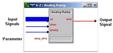
Although each symbol serves a special purpose, all symbols share some basic properties. These are inputs, outputs, and parameters.
Example: Analog Ramp symbol
Inputs
Symbol inputs allow signals to be connected from other parts of the program. Depending upon the symbol type, the current state of the input signal(s) may affect one or more output signal(s). Some symbols have a fixed number of inputs, while others can have a variable number of inputs, determined by the programmer based upon need.
Outputs
Except for a few special cases, the ultimate purpose of a symbol is to modify the states of its outputs. These outputs states will depend upon the symbol type, the current or past states of the input signals, and the values of the parameters. Because the symbol alone determines the states of its output signal(s), the symbol is considered the driving source for the output signals. Depending on the nature of signal, some outputs can have more than one driving source.
Similar to symbol inputs, the number of symbol outputs is fixed for some symbols, or can be variable based on need for other symbols.
Parameters
Some symbols also have parameters, which are constant values that help determine how the symbol behaves. For example, a symbol that delays an action for a specified period of time would have a parameter determining how long the delay should be for. The exact function of a parameter depends solely on the symbol type itself.
16 • Crestron SIMPL Windows |
Primer – DOC. 6253 |

Crestron SIMPL Windows |
Software |
For convenience, parameters may be expressed in a variety of formats (all of which are directly related to one another). Although a parameter will default to one format based upon the symbol type, you can alter the format by changing the format specifier at the end of the value.
Listed below are the valid formats, where the character in parentheses represents the format identifier.
•(d)ecimal
•(h)exadecimal
•(%) percentage of 65535
•(s)econds
•(t)icks – 1 tick = 1/100 seconds (2-Series); or 1/112.5 seconds (X-Series)
•(')character(') (single byte)
To set a parameter to a specific format, add the identifier after the value, i.e., 25%; if the parameter is a single byte, place single quotes before and after the ASCII character.
Parameters can also specify the time of day. Here the time of day is expressed in military time followed by the “seconds” format specifier, as follows:
•HH.MM.SS.HSs
•MM.SS.HSs
•SS.HSs
•SSs
•.HSs
Where HH = hours; MM = minutes; SS = seconds; and HS = hundredths of a second.
For example, the parameter 20.03.05s signifies a time value of 20 minutes, 3 seconds, and 5 hundredths of a second. When using this notation you can leave out the larger units if you are not using them, thus "3.00.00s" would mean 3 minutes, 0 seconds, and 0 hundredths of a second (it would NOT mean 3 hours).
Depending on the function of a symbol, a parameter can be signed or unsigned. Signed values range from–32768 to +32767; unsigned values range from 0 to 65535. Percentages can also be expressed as negatives, i.e., -25% = 25% of 65536, or 16384. (-16384 = 49152d). Thus a parameter of -25% is the same as 49152d. Refer to the SIMPL Windows help file for further information on valid parameter values.
NOTE: Parameters are constants whose value must be known at compile time. The value of the parameter cannot be changed while the program is running (e.g. a signal cannot be assigned to a parameter). To change a parameter, the program must be changed and recompiled.
Signal Types
The concept of the signal has already been broached. Signals are the elements used in your program to interconnect the various device and logic symbols that comprise your program. However the discussion of signals does not end there. For starters, signals can be one of three types: digital, analog, or serial. For any given signal, the signal type is determined by the driving source. If the symbol that drives the signal
Primer – DOC. 6253 |
Crestron SIMPL Windows • 17 |
Loading...