


 Loading...
Crestron AV2 & PRO2
2-Series Integrated Dual Bus Control System
Operations Guide

This document was prepared and written by the Technical Documentation department at:
Crestron Electronics, Inc.
15 Volvo Drive
Rockleigh, NJ 07647
1-888-CRESTRON
All brand names, product names and trademarks are the property of their respective owners. ©2006 Crestron Electronics, Inc.
Crestron AV2 & PRO2 |
2-Series Integrated Dual Bus Control System |
Contents
2-Series Integrated Dual Bus Control System: AV2 & PRO2 |
1 |
Introduction ............................................................................................................................... |
1 |
Features and Functions................................................................................................ |
1 |
Specifications .............................................................................................................. |
3 |
Physical Description.................................................................................................... |
5 |
Industry Compliance ................................................................................................... |
9 |
Setup ........................................................................................................................................ |
10 |
Network Wiring......................................................................................................... |
10 |
Identity Code ............................................................................................................. |
10 |
Hardware Hookup ..................................................................................................... |
10 |
Programming Software............................................................................................................ |
14 |
Earliest Version Software Requirements for the PC ................................................. |
14 |
Programming with Crestron SystemBuilder.............................................................. |
14 |
Programming with SIMPL Windows ........................................................................ |
14 |
Example Program ...................................................................................................... |
15 |
Uploading and Upgrading........................................................................................................ |
16 |
Establishing Communication..................................................................................... |
16 |
Programs and Firmware ............................................................................................ |
17 |
Operation ................................................................................................................................. |
18 |
Problem Solving ...................................................................................................................... |
23 |
Possible Problems with the Control System.............................................................. |
23 |
Serial Communication Difficulties with Other Devices Connected to the Control |
|
System ....................................................................................................................... |
24 |
Check Network Wiring.............................................................................................. |
26 |
Reference Documents................................................................................................ |
27 |
Further Inquiries ........................................................................................................ |
27 |
Future Updates .......................................................................................................... |
27 |
Software License Agreement................................................................................................... |
28 |
Return and Warranty Policies .................................................................................................. |
30 |
Merchandise Returns / Repair Service ...................................................................... |
30 |
CRESTRON Limited Warranty................................................................................. |
30 |
Operations Guide – DOC. 5957B |
Contents • i |

Crestron AV2 & PRO2 |
2-Series Integrated Dual Bus Control System |
2-Series Integrated Dual Bus
Control System: AV2 & PRO2
Introduction
Features and Functions
•2-Series engine with Dual-bus architecture
•36 MB of Internal Memory1
•4 GB Compact Flash memory card slot
•Cresnet port – master/slave selectable
•10/100 Ethernet capable with SSL encryption
•Crestron e-Control 2 and Crestron RoomView enabled
•Built-in firewall, NAT and router
•Six Com ports, eight IR/serial ports, eight Versiport I/O ports, eight relay ports
•Three Y-Bus2 / One Z-Bus control card expansion slots
•Internal power supply
•2-Space EIA rack-mountable
•Front panel control with LCD display (PRO2 only)
1.For more information on internal memory, refer to “2-Series Memory & Directory Structure” in the latest version of the Crestron 2-Series Control System Reference Guide (Doc. 6256), which is available from the Crestron website (http://www.crestron.com/manuals).
2.Optional on AV2.
2-Series Engine
At the heart of the AV2 & PRO2 is the powerful 32-bit Freescale ColdFire® processor. Crestron's exclusive enhanced real-time operating system makes the AV2 & PRO2 the fastest, most reliable control systems available.
Dual Bus Architecture
The AV2’s & PRO2's unique dual-bus architecture affords ultra fast communications. The 40 Mbps Y-Bus provides a high-speed backplane for IR, serial and other integrated control ports. Additional control ports and interfaces like MIDI and digital audio processing may be added by installing up to three Y-Bus control
Operations Guide – DOC. 5957B |
2-Series Integrated Dual Bus Control System: AV2 & PRO2 • 1 |
2-Series Integrated Dual Bus Control System |
Crestron AV2 & PRO2 |
cards (expansion cage option required for AV2). At a blazing 300 Mbps, the Z-Bus supports Fast Ethernet with future support for other emerging technologies.
Cresnet®
Cresnet is the communications backbone for many Crestron touchpanels, keypads, lighting controls and other devices. The Cresnet bus is a simple, yet flexible 4-wire network that provides rock-solid bidirectional communication and power for up to 252 Cresnet devices.
Cresnet Slave Mode
Selectable Cresnet Slave Mode enables the AV2 & PRO2 to be configured as Cresnet slave devices, effectively transforming them into Cresnet expansion modules. Such flexibility can offer a cost-effective solution for system expansion, providing a host of additional control ports in a single module.
Ethernet
Crestron pioneered the IP-based control system to harness the vast possibilities of Ethernet and the Internet for remote control, monitoring, programming and diagnostics. The AV2 & PRO2 are designed to deliver the world's most advanced IP control solutions. A choice of single or dual port Ethernet cards enables a full-duplex 10/100 Ethernet connection with built-in Web server and email client and support for both static and dynamic IP addressing.
Crestron e-Control®2
Crestron's award-winning e-Control 2 XPanel solutions offer the most flexible range of IP control possibilities available. Using a Windows® computer or CE/PocketPC™ PDA device, e-Control 2 provides an amazing control GUI that looks and behaves just like a Crestron Isys® touchpanel.
Crestron RoomView®
Every Ethernet-enabled 2-Series control system works directly with Crestron's exclusive RoomView Help Desk software for the industry's most comprehensive facility-wide asset management solution.
SSL
All Ethernet-enabled 2-Series control systems support SSL (Secure Sockets Layer), the industry standard for protecting sensitive network communications.
NAT
The AV2’s & PRO2's onboard NAT (Network Address Translator) acts as a firewall and router to facilitate the configuration of a private control LAN with a single-point connection to the client's LAN (Dual-port Ethernet card required).
Memory Expansion
A memory card slot accessible on the rear panel allows for easy expansion of the AV2’s & PRO2's internal memory using any Type II Compact Flash memory card up to 4 GB. Note that compact flash memory supports FAT file structure.
2 • 2-Series Integrated Dual Bus Control System: AV2 & PRO2 |
Operations Guide – DOC. 5957B |
Crestron AV2 & PRO2 |
2-Series Integrated Dual Bus Control System |
Front Panel Control (PRO2 only)
The PRO2 includes a programmable front control panel with LCD display and control port status indicators. The PRO2's front panel serves as a ready user interface for system configuration and diagnostics and can also be custom programmed to enable menu-driven control capability.
Specifications
Specifications for the AV2 & PRO2 are listed in the following table.
AV2 & PRO2 Specifications
|
SPECIFICATION |
|
DETAILS |
||
|
|
|
|
|
|
|
Processor |
|
|
|
|
|
CPU |
|
32-bit Freescale Coldfire Microprocessor |
||
|
Processing Speed |
|
257 MIPS (Dhrystone 2.1 benchmark) |
||
|
Memory |
|
|
|
|
|
SDRAM |
|
|
32 MB |
|
|
NVRAM |
|
|
256 kB |
|
|
Flash |
|
|
4 MB |
|
|
Compact Flash |
|
|
expandable up to 4 GB (not included) |
|
|
Operating System |
|
Real-time preemptive multi- |
||
|
|
|
|
threaded/multitasking kernel; FAT32 file |
|
|
|
|
|
system with long names; supports SIMPL |
|
|
|
|
|
Windows and SIMPL+ |
|
|
Ethernet |
|
|
|
|
|
With C2ENET-1 |
|
|
10/100BaseT, auto-negotiating, full/half |
|
|
|
|
|
duplex, static IP or DHCP/DNS, SSL, |
|
|
|
|
|
TCP/IP, UDP/IP, CIP, SMTP, built-in Web |
|
|
|
|
|
server and e-mail client; supports Crestron |
|
|
|
|
|
e-Control 2 Xpanel and RoomView |
|
|
|
|
|
applications |
|
|
With C2ENET-2 |
|
|
All above features plus: built-in firewall, |
|
|
|
|
|
router and network address translator |
|
|
|
|
|
(NAT) |
|
|
Expansion Slots |
|
|
|
|
|
Y-Bus1 |
|
(3) (AV2 requires CAGE2 accessory, sold |
||
|
|
|
|
separately); Accept all Y-Bus control cards |
|
|
Z-Bus2 |
|
(1) Accepts all Z-Bus control cards |
||
|
Power Requirements |
|
|
|
|
|
Internal Universal Power |
|
|
2.3 Amps, 100-250 Volts AC, 50/60 Hz |
|
|
|
|
|
||
|
Supply |
|
|
|
|
|
Available Cresnet Power |
|
|
50 Watts (shared with control card |
|
|
|
|
|
expansion slots) |
|
|
Network Power Fuse Rating |
|
4A, 250V (1 ¼” x ¼” Slow Blow Fuse |
||
|
|
|
|
Series) |
|
|
|
|
|
50 watts (DC) available for Cresnet devices |
|
|
Environmental |
|
|
|
|
|
Temperature |
|
|
41º to 113ºF (5º to 45ºC) |
|
|
Humidity |
|
|
10% to 90% RH (non-condensing) |
|
(Continued on following page)
Operations Guide – DOC. 5957B |
2-Series Integrated Dual Bus Control System: AV2 & PRO2 • 3 |
2-Series Integrated Dual Bus Control System |
Crestron AV2 & PRO2 |
|
|
|
AV2 & PRO2 Specifications (Continued) |
|
|
|
|
|
|
|
SPECIFICATION |
DETAILS |
|
|
|
|
|
|
Enclosure |
Black metal, 2U 19” rack-mountable |
|
|
|
(rack ears included) |
|
|
Dimensions |
|
|
|
Height |
3.47 in (8.82 cm) |
|
|
Width |
19.00 in (48.26 cm) with ears; |
|
|
|
17.03 in (43.25 cm) without ears |
|
|
Depth |
9.69 in (24.61 cm) |
|
|
Weight |
|
|
|
AV2 |
7.1 lbs (3.22 kg) – with line cord |
|
|
PRO2 |
8.0 lbs (3.63 kg) – with line cord |
|
|
Available Accessories |
|
|
|
CAGE2 (AV2 only) |
3-Card expansion cage |
|
|
C2ENET-1 |
Single port Ethernet card |
|
|
C2ENET-2 |
Dual port Ethernet card |
|
|
C2COM-2 |
Dual COM port card3 |
|
|
C2COM-3 |
Three COM port card3 |
|
|
C2IR-8 |
8 IR/Serial output card3 |
|
|
CNXIO-16 |
16 I/O Versiport card3 |
|
|
CNXAO-8 |
8 Analog output card3 |
|
|
CNXRY-8 |
8 Relay card3 |
|
|
CNXRY-16 |
16 Relay card3 |
|
|
CNXMIDI |
MIDI Interface card3 |
|
|
C2VEQ-4 |
4-Channel Volume/EQ and 4x4 matrix |
|
|
|
mixer card3 |
|
|
CNXTA |
Telephone interface and Voice/WAV sound |
|
|
|
card3 |
|
|
C2N-HBLOCK |
Cresnet Network Distribution Block |
|
|
C2N-NPA8 |
Cresnet Network Poll Accelerator |
|
|
C2N-SPWS300 |
300 Watt Cresnet Power Supply |
|
|
CNSP-XX |
Custom Serial Interface Cable |
|
|
IRP2 |
IR Probe |
|
|
|
|
|
1.40 Mb/s parallel communications; Internal backplane for integrated control ports and Y-Bus expansion slots.
2.300 Mb/s parallel communications; Backplane for Z-Bus expansion slots.
3.AV2 requires CAGE2 for card installation.
4 • 2-Series Integrated Dual Bus Control System: AV2 & PRO2 |
Operations Guide – DOC. 5957B |
Crestron AV2 & PRO2 |
2-Series Integrated Dual Bus Control System |
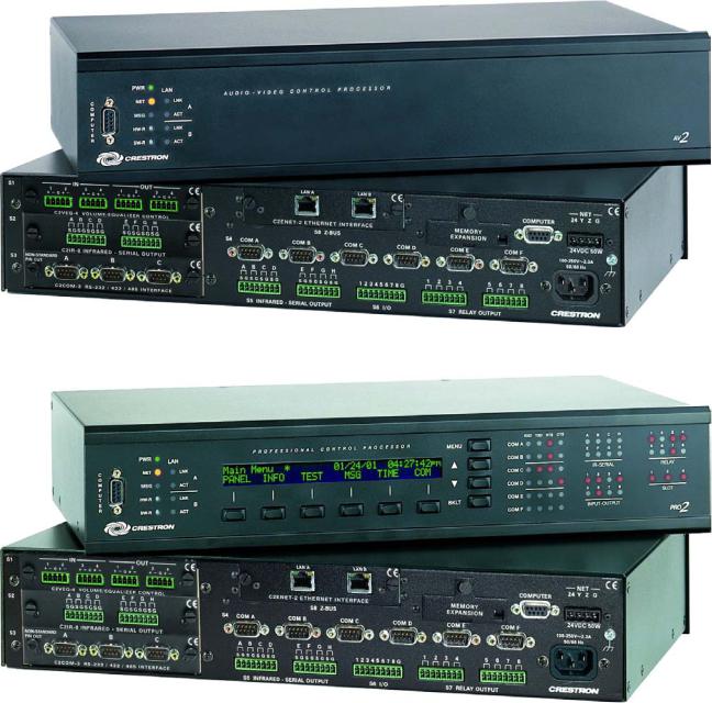
Physical Description
This section provides information on the connections, controls and indicators available on your AV2 & PRO2.
AV2 Physical View (shown with accessory cards installed in CAGE2; optional)
PRO2 Physical View (shown with accessory cards installed)
Operations Guide – DOC. 5957B |
2-Series Integrated Dual Bus Control System: AV2 & PRO2 • 5 |

2-Series Integrated Dual Bus Control System |
|
Crestron AV2 & PRO2 |
||||
AV2 & PRO2 Overall Dimensions |
|
|
|
|||
1 |
2 |
3 |
4 |
5 |
6 |
7 |
8 |
9 |
10 |
11 |
12 |
9.69 in
(24.61 cm)
17.03 in
(43.25 cm)
1 13
3.47 in
(8.82 cm)
14 |
15 |
16 |
17 |
18 |
19 |
6 • 2-Series Integrated Dual Bus Control System: AV2 & PRO2 |
Operations Guide – DOC. 5957B |
Crestron AV2 & PRO2 |
2-Series Integrated Dual Bus Control System |
Connectors, Controls & Indicators
# |
CONNECTORS1, |
|
|
DESCRIPTION |
|
|
CONTROLS & INDICATORS |
|
|
|
|
1 |
COMPUTER |
DB9F connectors (one on front panel and one on rear) are used |
|||
|
|
|
when programming with a PC. Each port is modem compatible. |
||
|
|
|
(Modem and PC cables not included.) |
||
|
FRONT PANEL |
REAR PANEL |
|
|
|
2 |
PWR LED |
Indicates 24 Volts DC power supplied from Cresnet control network. |
|||
3 |
NET LED |
Indicates communication with Cresnet System. |
|||
4 |
MSG LED2 |
Illuminates when a message is detected. To decipher content, |
|||
|
|
|
examine the message available from the menu function buttons or |
||
|
|
|
through the Crestron Toolbox™. |
||
5 |
COM (A – F) LEDS3 |
RXD - Illuminate during reception of data from serial devices |
|||
|
|
|
attached to the respective COM ports. |
||
|
|
|
TXD – Illuminate during transmission of data to serial devices |
||
|
|
|
attached to the respective COM ports. |
||
|
|
|
RTS – Illuminate to reflect state of the RTS pin on the respective |
||
|
|
|
COM port. If no handshaking is specified, the RTS line will be high |
||
|
|
|
and the associated LED is also high. When RTS flow control is |
||
|
|
|
enabled, RTS indicates the unit is ready to receive data from serial |
||
|
|
|
devices attached to the respective COM ports. |
||
|
|
|
CTS – Illuminate to reflect state of the CTS pin on the respective |
||
|
|
|
COM port. An illuminated LED means the CTS line is high. When |
||
|
|
|
CTS flow control is enabled, CTS indicates the serial devices on the |
||
|
|
|
respective COM ports are ready to accept data. |
||
6 |
IR – SERIAL (A – H) LEDS3 |
Indicate activity on the respective IR-SERIAL lines. |
|||
7 |
RELAY (1 – 8) LEDS3 |
Indicate the respective relay is closed. |
|||
8 |
RESET BUTTONS |
HW-R - Initiates system hardware reset. |
|||
|
|
|
SR-R - Pressing this in combination with HW-R button performs a |
||
|
|
|
system restart without loading the program. Pressing it alone |
||
|
|
|
momentarily while the system is running restarts the program. |
||
9 |
LAN (A – B) LEDS4 |
LNK – Indicate the Ethernet card has established a valid Ethernet |
|||
|
|
|
connection. |
|
|
|
|
|
ACT – Indicate communication (activity) at the respective port on the |
||
|
|
|
Ethernet card. |
|
|
10 |
LCD SCREEN & MENU |
Permits local control; refer to “Operation” on page 18 for details. |
|||
|
BUTTONS3 |
|
|
|
|
11 |
INPUT – OUTPUT |
Indicate when input voltage thresholds for the respective I/O ports |
|||
|
(1 – 8) LEDS3 |
are exceeded or when the output is active. |
|||
12 |
SLOT (1 – 3) LEDS3 |
Indicate an expansion card is inserted into the respective slot. |
|||
|
|
|
These LEDS turn off momentarily when data is sent to the card or |
||
|
|
|
received from the card. |
||
13 |
NET |
|
Four-position terminal block connector for data and power. |
||
|
|
|
Connects to Cresnet control network. |
||
|
|
|
Pin 1 |
(24) |
Power |
|
|
|
Pin 2 |
(Y) |
Data |
|
|
|
Pin 3 |
(Z) |
Data |
|
|
|
Pin 4 (G) Ground |
||
(Continued on following page) |
|
|
|
|
|
Operations Guide – DOC. 5957B |
2-Series Integrated Dual Bus Control System: AV2 & PRO2 • 7 |
Loading...