


MPS-100
Table of contents
 Loading...
Crestron MPS-100
Multimedia Presentation System 100
Operations Guide
Important Safety Instructions
This document was prepared and written by the Technical Documentation department at:
Crestron Electronics, Inc.
15 Volvo Drive
Rockleigh, NJ 07647
1-888-CRESTRON
• Read these instructions.
• Keep these instructions.
• Heed all warnings.
• Follow all instructions.
• Do not use this apparatus near water.
• Clean only with dry cloth.
• Do not block any ventilation openings. Install in accordance
with the manufacturer’s instructions.
• Do not install near any heat sources such as radiators, heat
registers, stoves, or other apparatus (including amplifiers) that
produce heat.
• Do not defeat the safety purpose of the polarized or groundingtype plug. A polarized plug has two blades with one wider than
the other. A grounding-type plug has two blades and a third
grounding prong. The wide blade or the third prong are
provided for your safety. If the provided plug does not fit into
your outlet, consult an electrician for replacement of the
obsolete outlet.
• Protect the power cord from being walked on or pinched
particularly at plugs, convenience receptacles, and the point
where they exit from the apparatus.
• Only use attachments/accessories specified by the
manufacturer.
• Unplug this apparatus during lightning storms or when unused
for long periods of time.
• Refer all servicing to qualified service personnel. Servicing is
required when the apparatus has been damaged in any way,
such as power-supply cord or plug is damaged, liquid has been
spilled or objects have fallen into the apparatus, the apparatus
has been exposed to rain or moisture, does not operate
normally, or has been dropped.
• Disconnect power prior to connecting or disconnecting
equipment.
• Do not install in direct sunlight.
• The apparatus must be installed in a way that the power cord
can be removed either from the wall outlet or from the device
itself in order to disconnect the mains power.
WARNING:
TO REDUCE THE RISK OF FIRE OR ELECTRIC SHOCK,
DO NOT EXPOSE THIS APPARATUS TO RAIN OR
MOISTURE. THE APPARATUS SHALL NOT BE
EXPOSED TO DRIPPING OR SPLASHING. OBJECTS
FILLED WITH LIQUIDS, SUCH AS VASES, SHOULD
NOT BE PLACED ON THE APPARATUS.
WARNING:
TO PREVENT ELECTRIC SHOCK, DO NOT REMOVE
COVER. THERE ARE NO USER SERVICEABLE PARTS
INSIDE. ONLY QUALIFIED SERVICE PERSONNEL
SHOULD PERFORM SERVICE.
The lightning flash with arrowhead symbol, within an
equilateral triangle, is intended to alert the user to the
presence of uninsulated “dangerous voltage” within the
product’s enclosure that may be of sufficient magnitude to
constitute a risk of electric shock to persons.
The exclamation point within an equilateral triangle is
intended to alert the user to the presence of important
operating and maintenance (servicing) instructions in the
literature accompanying the appliance.
WARNING:
THIS IS AN APPARATUS WITH CLASS I
CONSTRUCTION. IT SHALL BE CONNECTED TO AN
ELECTRICAL OUTLET WITH AN EARTHING GROUND
TERMINAL.
IMPORTANT:
The MPS-100 can be used with Class 2 output wiring.
• Prevent foreign objects from entering the device.
All brand names, product names and trademarks are the property of their respective owners.
©2006 Crestron Electronics, Inc.

Crestron MPS-100 Multimedia Presentation System 100
Contents
Multimedia Presentation System 100: MPS-100 1
Introduction ...............................................................................................................................1
Features and Functions................................................................................................ 1
Applications.................................................................................................................4
Internal Block Diagram ............................................................................................... 5
Specifications ..............................................................................................................6
Physical Description.................................................................................................... 8
Industry Compliance .................................................................................................17
Setup ........................................................................................................................................ 18
Network Wiring......................................................................................................... 18
Ethernet .....................................................................................................................18
CAT5 Wiring............................................................................................................. 18
QuickMedia Wiring................................................................................................... 18
Installation................................................................................................................. 20
Hardware Hookup .....................................................................................................21
Configuring the RGB Input Ports.............................................................................. 23
Programming Software............................................................................................................26
Earliest Version Software Requirements for the PC .................................................26
Programming with Crestron SystemBuilder.............................................................. 26
Programming with SIMPL Windows........................................................................ 27
Switching Programs...................................................................................................28
Saving Settings .......................................................................................................... 28
Example Program...................................................................................................... 28
Uploading and Upgrading........................................................................................................ 29
Establishing Communication.....................................................................................29
Programs and Firmware ............................................................................................30
Configuration and Operation ...................................................................................................31
Configuration.............................................................................................................31
Operation................................................................................................................... 58
Problem Solving ......................................................................................................................66
Troubleshooting......................................................................................................... 66
Check Network Wiring..............................................................................................68
Reference Documents................................................................................................ 69
Further Inquiries........................................................................................................ 70
Future Updates ..........................................................................................................70
Software License Agreement................................................................................................... 71
Return and Warranty Policies.................................................................................................. 73
Merchandise Returns / Repair Service ......................................................................73
CRESTRON Limited Warranty.................................................................................73
Operations Guide – DOC. 6527 Contents • i


Crestron MPS-100 Multimedia Presentation System 100
Multimedia Presentation System 100: MPS-100
Introduction
Features and Functions
• Multimedia system switcher and control system
• Out-of-the-box switching and audio control
• Two video/HDTV and three RGB/computer inputs
• Built-in input signal sensing | auto-switching capable
• Separate display and touchpanel preview outputs
• QuickMedia™ and Crestron Home
• Five balanced stereo audio inputs | Built-in 40 watt amplifier
• 8 ohm stereo and 70/100V mono versions available
• 2-Series control engine | e-Control
• 10/100 Ethernet | RoomView
• Two RS-232, four IR, four digital in, & four relay control ports
• Front panel setup and control | Backlit LCD display
• Keypad, touchpanel, and wireless control options
• Internal power supply | two-space rack-mountable
The Multimedia Presentation System 100 (MPS-100) is a complete presentation
control and signal routing solution for boardrooms and classrooms. Integrating a
control system, multimedia switcher, audio controls and amplifier into a single two-
space rack mount package, the MPS-100 eliminates the need for separate
components without forfeiting performance or flexibility.
System Switcher
®
CAT5 AV connectivity
®
2 Web server
®
and SNMP support
The MPS-100 provides high-performance switching of two video and three RGB
computer sources to a single projector or plasma display. Composite, S-video,
component and RGBHV signals can be sensed and routed to the appropriate input on
the display device, with control of the display provided via Ethernet, RS-232 or IR.
Input signal detection is provided on every video and RGB input to enable auto-
switching functionality and provide device power status information to the control
system. Selectable sync impedance on each RGB input helps accommodate cable
runs of varying lengths.
Operations Guide – DOC. 6527 Multimedia Presentation System 100: MPS-100 • 1

Multimedia Presentation System 100 Crestron MPS-100
Touchpanel Output
A second discrete output is provided on the MPS-100 to feed a preview signal to the
system touchpanel or other monitor. This output is controlled separately from the
main display output, allowing a different source to be viewed on the touchpanel. The
touchpanel connection is facilitated through a choice of QuickMedia (QM) or
Crestron Home (CH) CAT5 Balanced Video outputs, simplifying wiring to a wide
range of Crestron
HDTV plus audio, while the CH output is limited to standard video and HDTV only
(dependent upon the capabilities of the touchpanel). RGBHV inputs are only
displayed on the QM output.
QuickMedia
The QM touchpanel output can also be used to feed signals straight to the primary
display device, providing a very streamlined, low-cost, long-distance wiring solution.
Crestron's exclusive QuickMedia transport transmits high-resolution RGB, HD
video, and stereo program audio signals up to 328 feet over a single inexpensive
CAT5e type cable. Just one CresCAT-QM cable and a QM receiver are all that is
required for complete signal routing and device control, eliminating all the bulky,
expensive cabling that would otherwise be needed.
®
touchpanels. The QM output supports high-resolution RGB and
Audio Features
Five stereo audio inputs accept balanced or unbalanced line-level signals from
computers and other program audio sources. To accommodate a wide range of
signals, adjustable input compensation is employed to help maintain consistent
volume levels when switching between sources.
In addition to volume adjustment, the MPS-100's main program output (PROG
OUT) includes adjustable bass, treble, balance, and mute. Professional balanced line
level outputs are provided, with mute relays for "thump" protection upon power up.
A separate "fixed-level" LINE OUT with electronic mute provides a second set of
balanced outputs to feed a recording device, codec, or assistive listening system.
The QM touchpanel output is controlled separately from the other audio outputs,
allowing a different program source to be monitored on the touchpanel, or output to
other audio equipment by way of an appropriate QM receiver or other QuickMedia
device.
Built-in Amplifier
A 40-watt amplifier (20 watts x2) is built into the MPS-100, with three models
available offering the choice of 8-ohm stereo, 70V mono (MPS-100-70V), or 100V
mono (MPS-100-100V) outputs. The term “MPS-100” is used throughout this guide
to denote all models. For larger rooms requiring more power, the MPS-100 supports
plug-and-play compatibility with Crestron's QM-Series amplifiers.
Front Panel Control
Out of the box, the MPS-100 front panel supports easy pushbutton routing of input
sources to each of the outputs, and audio volume adjustment using the volume
control knob. Dedicated buttons and indicators are also provided for separate control
of system power and projector power. In addition, five preset buttons are included
for custom functions such as lowering a projection screen, closing blinds, or
selecting a lighting preset.
The front panel label strips are easily customized using Crestron Engraver software
or standard 3/8" tape labels, allowing for the clear designation of each input, output,
and preset button. When selected, these functions will also appear on the LCD
2 • Multimedia Presentation System 100: MPS-100 Operations Guide – DOC. 6527

Crestron MPS-100 Multimedia Presentation System 100
display as generic names (Input 1, 2…), or as custom names (DVD, Podium PC,
Screen Up, etc.) which are easily entered using MediaManager Wizard software.
Easy setup of the MPS-100 is facilitated through the LCD display without
necessitating a computer. Together with four softkey buttons, four menu navigation
buttons and the volume knob, the LCD enables configuration of IP network, audio,
and other system settings. For security, the front panel controls can be password
protected or locked out.
2-Series Control System
Integrated into the MPS-100 is a Crestron 2-Series Ethernet control system complete
with Crestron e-Control 2 Web server and a host of RS-232, IR, digital input and
relay control ports for integration with third-party equipment. A basic AV
presentation room with projector, screen, keypad or small touchpanel, and wireless
remote control can easily be set up in minutes using the MediaManager Wizard
software. Or, a fully custom system can be programmed using SystemBuilder™ or
SIMPL™Windows® software. Either way, the MPS-100 works with Crestron's
RoomView Help Desk software, the industry's most comprehensive facility-wide
asset management solution.
Room Control Options
Without requiring any programming, the MPS-100 can be controlled simply using
Crestron's APAD LCD Controller or a selection of keypads such as the C2N-DB12,
CNX-B12, AND C2N-FTB. With custom programming, Crestron's complete line of
Isys® touchpanels and MediaManager FlipTops are supported. Equipped with an
optional CNXRMIRD IR receiver, the MPS-100 allows a third-party universal
remote to be used for a low-cost wireless control solution. Or, adding an RF wireless
gateway, infiNET™, or WiFi wireless LAN connection enables use of a wide range
of one-way and two-way RF wireless handheld remotes and touchpanels.
Operations Guide – DOC. 6527 Multimedia Presentation System 100: MPS-100 • 3
Multimedia Presentation System 100 Crestron MPS-100
Applications
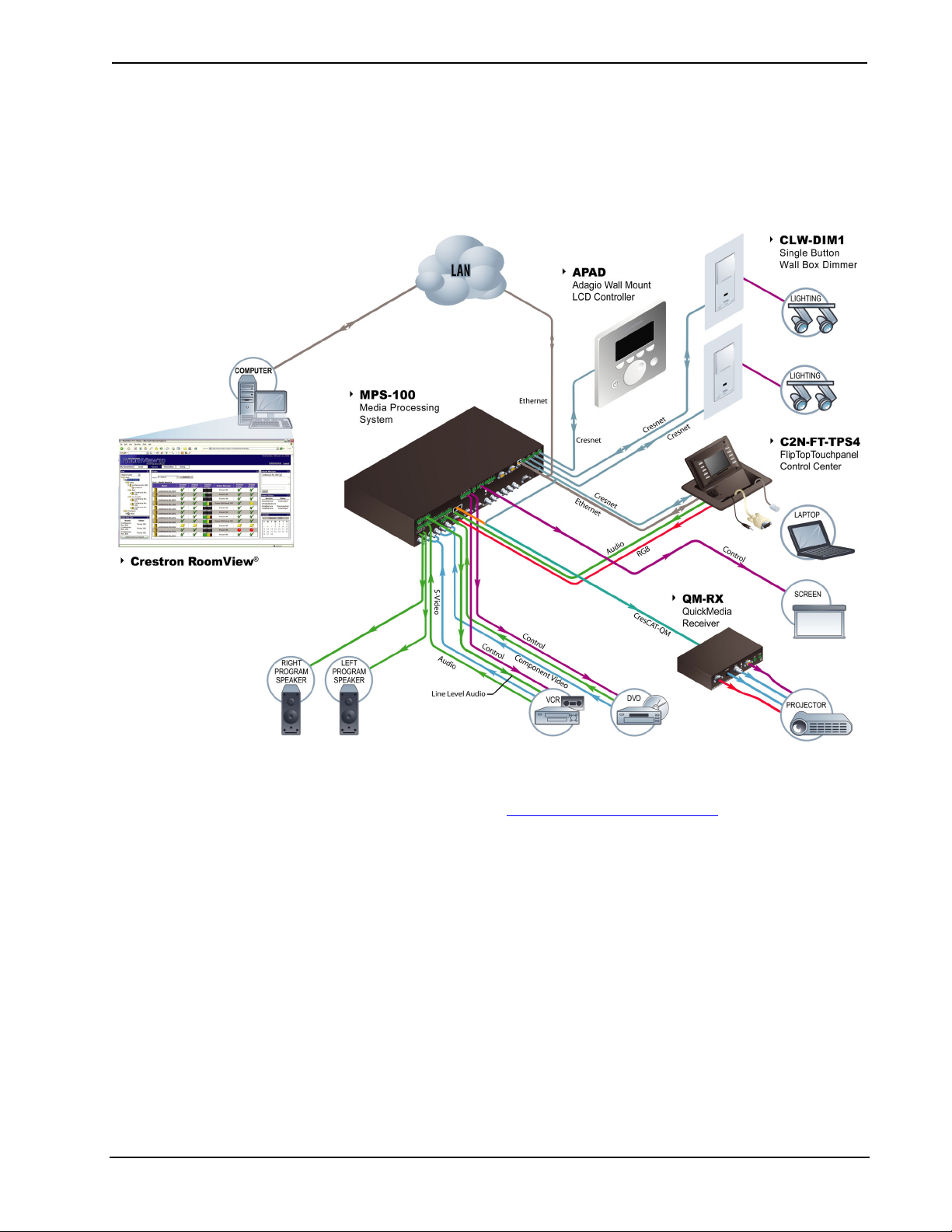
The following diagram shows an MPS-100 in a lecture hall application.
MPS-100 in a Lecture Hall Application
For more information on this and other QM applications, refer to the latest revision
of the Crestron MediaManager Applications Guide (Doc. 6244), which is available
from the Crestron website (http://www.crestron.com/manuals
4 • Multimedia Presentation System 100: MPS-100 Operations Guide – DOC. 6527
).
Crestron MPS-100 Multimedia Presentation System 100
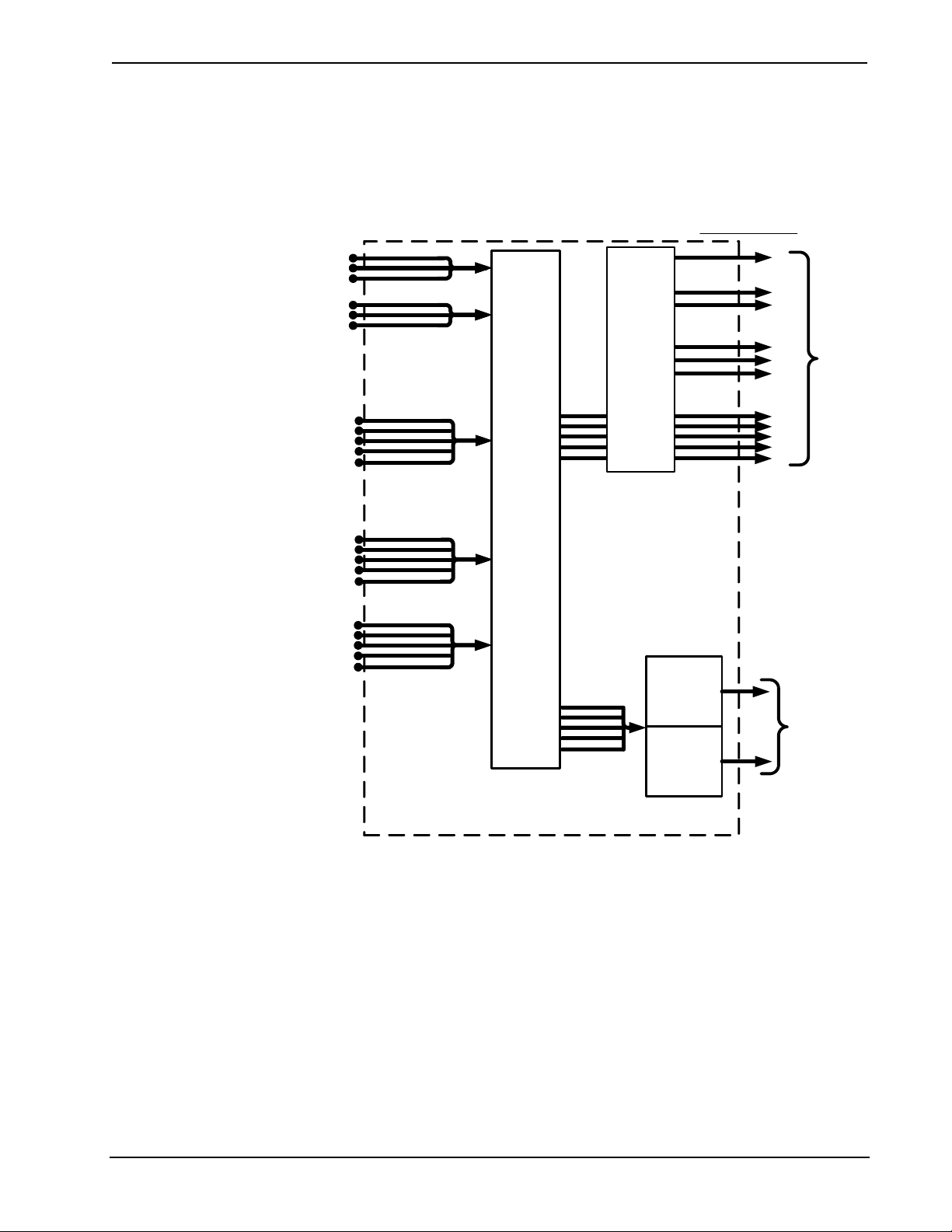
Internal Block Diagram
The following diagrams represent the video and audio switching abilities of the
MPS-100. For more information refer to “Configuration and Operation” on page 31.
Video Block Diagram of the MPS-100
VIDEO OUTPUTS
Vid/S-Vid/Component
1
Vid/S-Vid/Component
2
RGBHV
3
RGBHV
Select
1 of 4
5x2
Matrix
Switch
Composite
S-Video
Component
RGBHV
OUT 1
Select
1 of 4
4
RGBHV
5
RGBHV*/Vid
/S-Vid/
Component
Analog
Video to
QM
Analog
Video to
CH
QM OUT
OUT 2
TOUCH
PANEL
PORT
CH
BALANCED
VIDEO OUT
RJ-45
* RGBHV on QM OUT only.
The signal type routed to OUT 1 is the same as the input signal type. For example,
An S-video input signal will appear on the S-video output terminals when the signal
is routed to OUT 1. The MPS-100 does not convert input signal formats.
Operations Guide – DOC. 6527 Multimedia Presentation System 100: MPS-100 • 5
Multimedia Presentation System 100 Crestron MPS-100
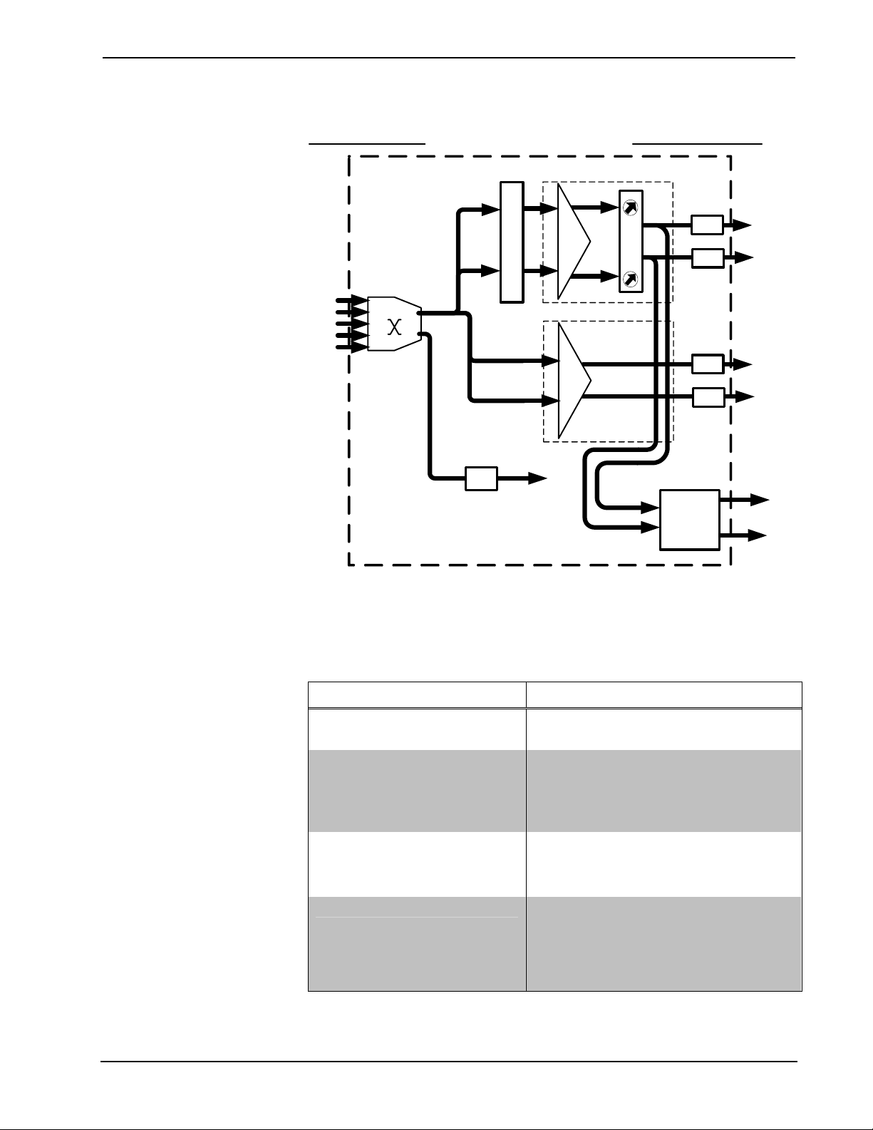
Audio Block Diagram of the MPS-100
AUDIO INPUTS AUDIO OUTPUTS
Volume / Tone / Balance / Mute
0 dB path / Mute
Line
L
Program L
MUTE
Program R
R
L
R
MUTE
MUTE
MUTE
Line Out L
Line Out R
Stereo
Audio
1
2
3
4
5
5 X 1
Switch
L
Pre-Amp
R
L
R
selector
Stereo / Mono
Drivers
A2D
QM
Amplifier
Specifications
Specifications for the MPS-100 are listed in the following table.
MPS-100 Specifications
SPECIFICATION DETAILS
Processor
CPU
Memory
SDRAM
NVRAM
Flash
Operating System
Ethernet
32-bit Freescale ColdFire
32 MB
256 KB
8 MB
Real-time, preemptive, multitasking kernel,
multi-threaded, FAT32 file system with long
names; supports SIMPL Windows and
SIMPL+
®
10/100BaseT, auto-negotiating, full/half
duplex, static IP or DHCP/DNS, SSL,
TCP/IP, UDP/IP, CIP, SMTP, SNMP, builtin Web server and e-mail client; supports
Crestron e-Control®2 XPanel and
RoomView® applications
2X20W
®
Microprocessor
Amplifier
Output
L
R
(Continued on following page)
6 • Multimedia Presentation System 100: MPS-100 Operations Guide – DOC. 6527
Crestron MPS-100 Multimedia Presentation System 100
MPS-100 Specifications (Continued)
SPECIFICATION DETAILS
Video/RGB
Switcher
Signal Types
Video/HDTV Formats
Video Gain
Video Bandwidth
RGB Formats
RGB Gain
Maximum RGB Resolution
Blanking Time
Sync Rise/Fall Time
Sync Latency
Audio
Switcher/Preamp
Volume Gain Range
Mute
Input Compensation
Bass Gain Range
Treble Gain Range
Frequency Response
S/N Ratio
THD+N
LCD Display
Power Requirements
Main Power
Available Cresnet Power
Environmental
Temperature
Humidity
Enclosure
5x2(x5) crosspoint matrix, 1x4 video/RGB
output selector
RGB and composite, S-video, or
component video (does not transcode)
NTSC or PAL, HDTV up to 1080i/1080p
0dB (75 ohms terminated)
150 MHz (-3dB) at unity gain
RGBHV or RGBS
0dB (75 ohms terminated)
WUXGA 1920 X 1200 pixels
< 0.1 second
3.5 ns maximum
< 30 ns
5x2 stereo crosspoint matrix, stereo
volume/tone control on PROGRAM output,
integrated power amplifier
-80dB to +20dB, 1 dB steps
-100dB (electronic), -120dB (relay)
±10dB
±12dB @ 100Hz, 2 dB steps
±12dB @ 10kHz, 2 dB steps
20Hz to 20kHz ±0.5dB
90 dB (program out), 90 dB (speaker out @
8 ohms) 20Hz to 20kHz A-weighted
<0.05% (program out), 0.7% (speaker out
@ 8 ohms) 20Hz to 20kHz
Green LCD alphanumeric, adjustable
backlight. Two lines x 20 characters per
line. Displays input/outputs by name,
volume level bargraph, setup menus,
time/date, and other system information
2.5 Amps @ 100-240 Volts AC, 50/60 Hz
30 Watts
41° to 104°F (5° to 40°C)
10% to 90% RH (non-condensing)
Black metal, 2U 19” rack-mountable (rack
ears included)
(Continued on following page)
Operations Guide – DOC. 6527 Multimedia Presentation System 100: MPS-100 • 7
Multimedia Presentation System 100 Crestron MPS-100
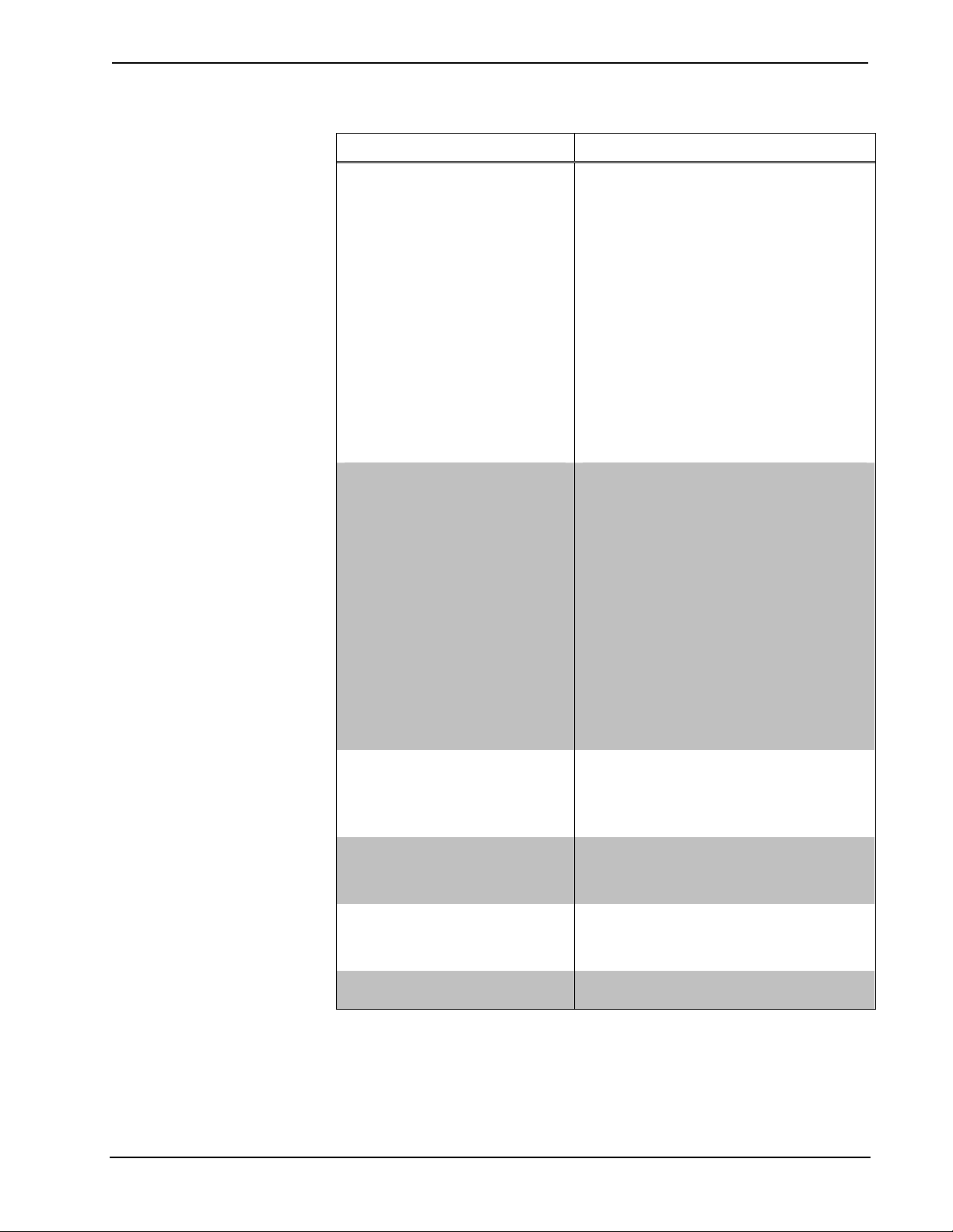
MPS-100 Specifications (Continued)
SPECIFICATION DETAILS
Dimensions
Height
Width
Depth
Weight: 8.8 lbs (4.0 kg)
Available Models:
MPS-100
MPS-100-70V
MPS-100-100V
Available Accessories:
APAD
C2N-DB12
CNX-B12
CNXRMIRD
QM-AMP3X80MM
QM-AMP3X80SR
CNSP-XX
IRP2
3.47 in (8.81 cm)
17.03 in (43.24 cm);
19.0 in (48.26 cm) with ears
12.54 in (31.86 cm)
Multimedia Presentation System 100
w/Stereo Amplifier
Multimedia Presentation System 100 with
70 Volt Amplifier
Multimedia Presentation System 100 with
100 Volt Amplifier
Wall Mount Controller
12-Button Decorator Keypad
12-Button Decorator Keypad
IR Receiver
3-Channel Multimedia Amplifier
3-Channel Sound Reinforcement Amplifier
Custom Serial Interface Cable
IR Probe
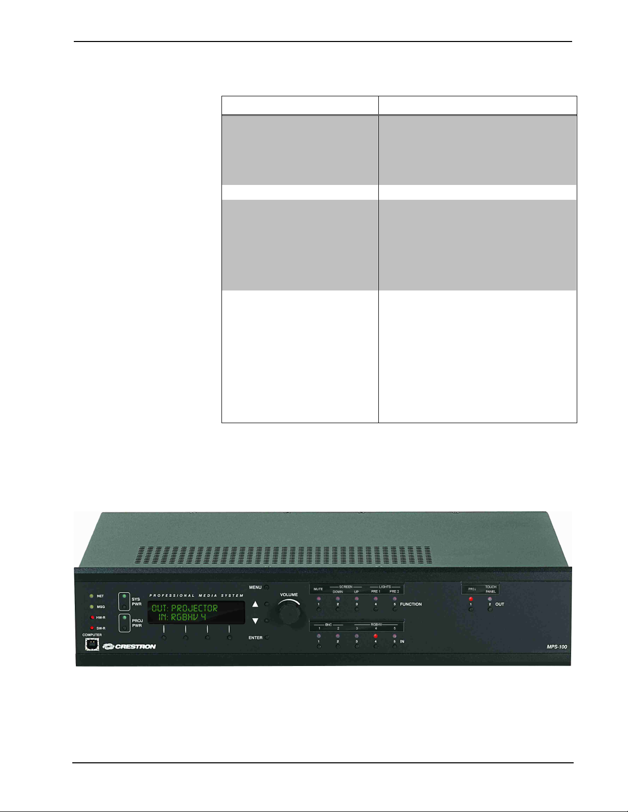
MPS-100 Physical View (Front)
Physical Description
This section provides information on the connections, controls and indicators
available on your MPS-100.
8 • Multimedia Presentation System 100: MPS-100 Operations Guide – DOC. 6527
Crestron MPS-100 Multimedia Presentation System 100
(
)
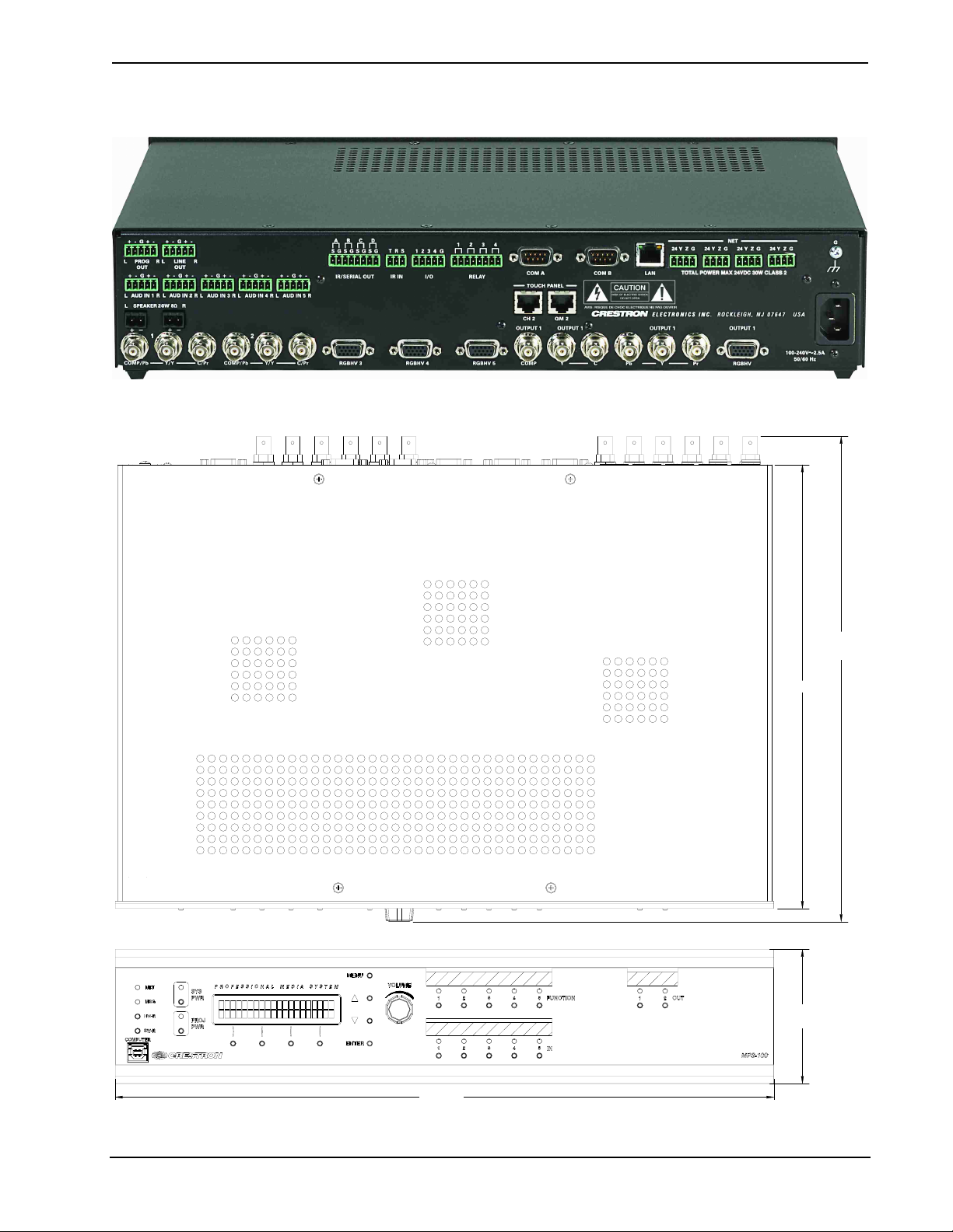
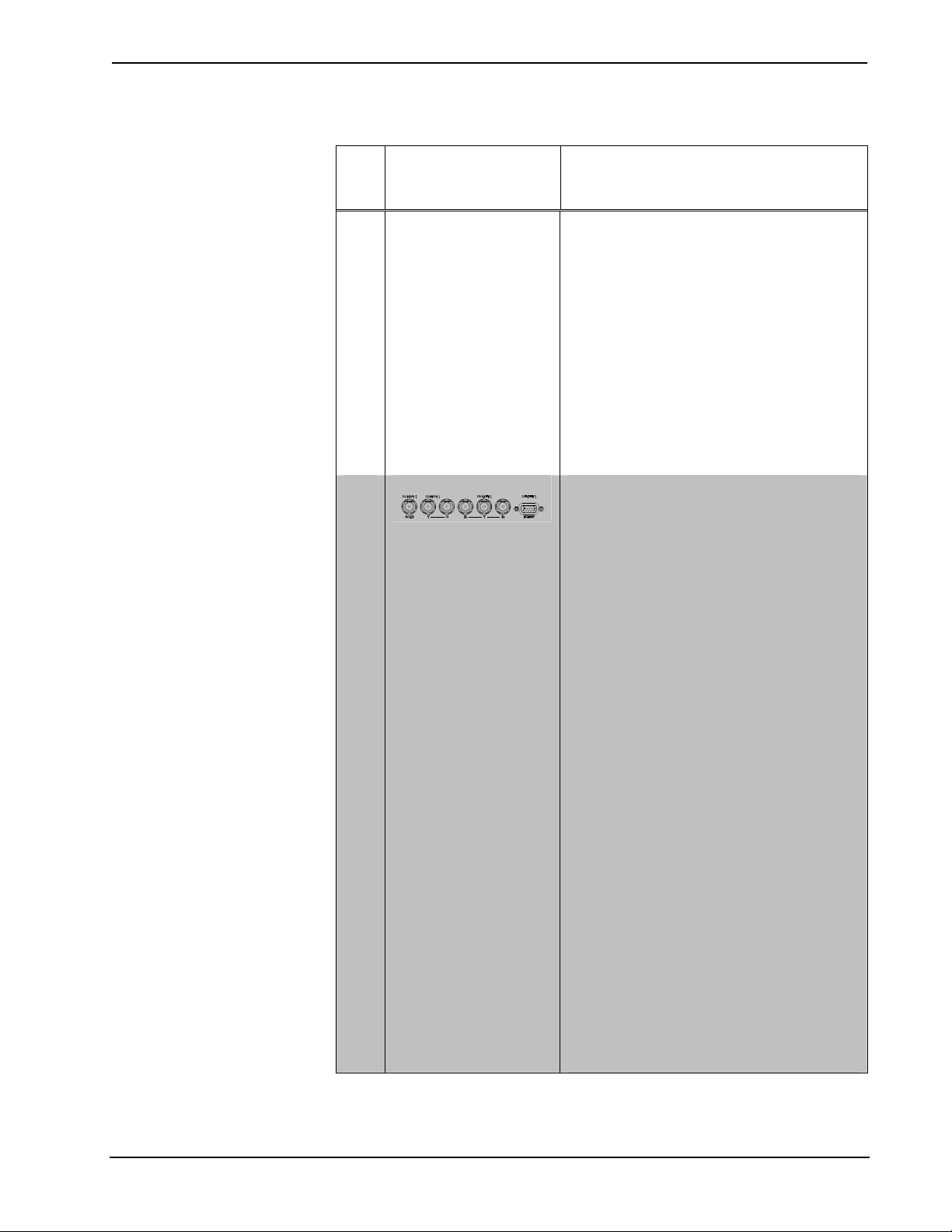
MPS-100 Physical View (Rear)
MPS-100 Overall Dimensions
17.03 in
43.24 cm
11.47 in
(29.13 cm)
3.47 in
(8.81 cm)
12.54 in
(31.86 cm)
Operations Guide – DOC. 6527 Multimedia Presentation System 100: MPS-100 • 9
Multimedia Presentation System 100 Crestron MPS-100
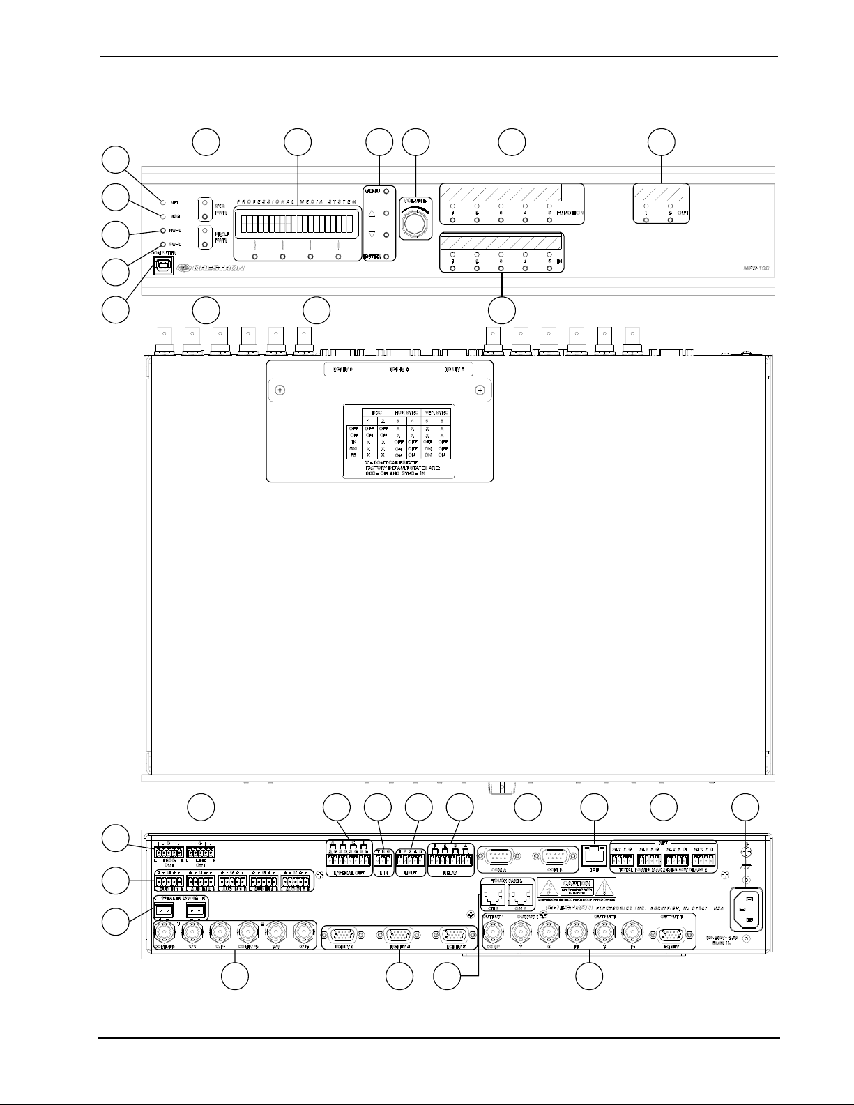
MPS-100 Buttons and Ports
10
13 171520
21
28
1
2
3
4
5
11
14
22
12
18 19
23 24
27
29 30
6
7
8
9
10 • Multimedia Presentation System 100: MPS-100 Operations Guide – DOC. 6527
16
25 26
Crestron MPS-100 Multimedia Presentation System 100
Connectors, Controls & Indicators
#
CONNECTORS
CONTROLS &
INDICATORS
1 NET LED Indicates communication with Cresnet devices.
2 MSG LED
3 & 4 RESET BUTTONS
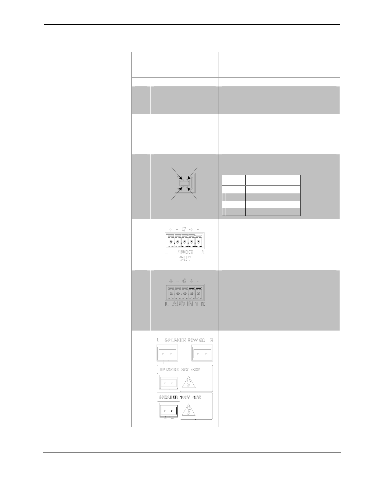
5
6
7
8
COMPUTER
Pin 4 Pin 3
Pin 1 Pin 2
PROGRAM OUT (L/R)
AUDIO INPUTS 1-5 (5) 5-pin 3.5mm detachable terminal blocks;
SPEAKER OUTPUTS
1
,
DESCRIPTION
Illuminates when a message is present in the
message log. To view the contents of the
message log, use the front panel buttons or
Crestron Toolbox™.
HW-R – Initiates system hardware reset.
SW-R – Pressing this in combination with
HW-R button performs a system restart without
loading the program. Pressing it alone
momentarily while the system is running
restarts the program.
(1) USB Type B female USB 1.1 computer
console port (cable included)
PIN DESCRIPTION
1 +5 VDC
2 Data -
3 Data +
4 Ground
(1) 5-pin 3.5 mm detachable terminal block;
Balanced/unbalanced stereo line-level output,
variable levels;
Output Impedance: 200 ohms balanced, 100
ohms unbalanced;
Maximum Output Level: 4 V
V
unbalanced
rms
balanced, 2
rms
Balanced/unbalanced stereo line-level inputs;
Input Impedance: 25k ohms
balanced/unbalanced;
Balanced Input Level: -20 to +12 dBV; 4 V
rms
maximum;
Unbalanced Input Level: -20 to +6 dBV; 2 V
rms
maximum
(2) 2-pin 7.62mm detachable terminal blocks;
Speaker-level audio outputs (MPS-100);
(1) 2-pin 7.62mm detachable terminal blocks;
Speaker-level audio outputs (MPS-100-70V
and MPS-100-100V)
Wire Size: Connector accepts 12 AWG
maximum
Output Power (MPS-100): 20W RMS per
channel stereo into 8 ohms, 4 ohms tolerant;
Output Power (MPS-100-70V): 40W RMS
mono at 70 Volts;
Output Power (MPS-100-100V): 40W RMS
mono at 100 Volts
(Continued on following page)
Operations Guide – DOC. 6527 Multimedia Presentation System 100: MPS-100 • 11
Multimedia Presentation System 100 Crestron MPS-100
Connectors, Controls & Indicators (Continued)
#
CONNECTORS
CONTROLS &
INDICATORS
1
,
DESCRIPTION
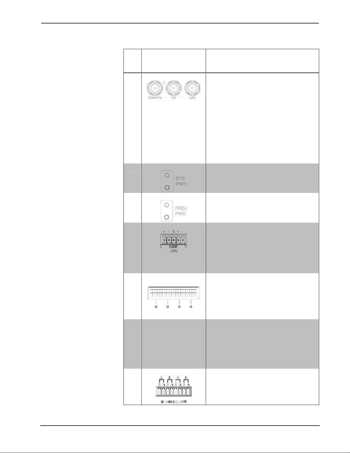
9
10
VIDEO INPUTS 1 & 2
SYSTEM POWER
11
12
PROJECTOR POWER (1) pushbutton and green LED, controls
LINE OUT
13
LCD DISPLAY AND
SOFT BUTTONS
14 RGB DIP SWITCHES
15
IR/SERIAL OUT
(2) sets of (3) BNC female video inputs, each
set configurable as:
• (1) Component/HDTV (YP
input, or
bPr
) video
• (1) S-video (Y/C) input, or
• (1) Composite input
Input Level: 1 V
nominal;
p-p
Input Impedance: 75 ohms nominal;
DC Offset: Insensitive to DC offset (AC
coupled);
Video signal detection on COMP/P
and Y/Y
b
(high/low)
(1) pushbutton and green LED, controls
system power
display device power
(1) 5-pin 3.5mm detachable terminal block;
Balanced/unbalanced stereo line-level output,
fixed levels;
Output Impedance: 200 ohms balanced,
100 ohms unbalanced;
Maximum Output Level: 4 V
2 V
unbalanced
rms
balanced,
rms
Green LCD alphanumeric, adjustable
backlight; 2 lines x 20 characters per line;
Displays input/outputs by name, volume level
bargraph, setup menus, time/date, and other
system information
(4) pushbuttons for activation of LCD driven
functions
(3) Banks of DIP switches for configuring the
horizontal and vertical sync impedances of
each RGB input. Each bank of DIP switches
can also be configured to simulate the
presence of a monitor to RGB outputs that
require a monitor to be connected. For more
information, refer to “Configuring the RGB
Input Ports” on page 23.
(4) 2-pin 3.5mm detachable terminal blocks,
IR/Serial output ports; IR output up to 1.2 MHz;
One-way serial TTL/RS-232 (0-5 Volts)
9600 baud
2
up to
(Continued on following page)
12 • Multimedia Presentation System 100: MPS-100 Operations Guide – DOC. 6527
Crestron MPS-100 Multimedia Presentation System 100
Connectors, Controls & Indicators (Continued)
#
CONNECTORS
CONTROLS &
INDICATORS
1
,
DESCRIPTION
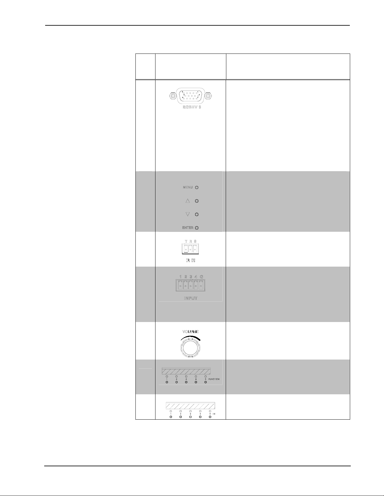
16
17
18
19
20
RGBHV INPUTS 3 - 5
NAVIGATION
BUTTONS
IR IN
INPUT
VOLUME CONTROL
(3) DB15HD female, RGBHV (VGA) inputs;
Format: RGBHV or RGBS;
RGB Input Level: 1 V
RGB Input Impedance: 75 ohms nominal;
Sync Input Level: 2 to 5 V
Sync Input Impedance: 75, 500, or 1k ohms
individually selectable for H and V via bottom
panel DIP switches (#14);
Video signal detection on “H-SYNC”;
Defeatable DDC pull-up resistors individually
selectable via internal DIP switches (#14)
(4) Pushbuttons for navigating the
configuration menus of the MPS-100
(1) 3-pin 3.5 mm detachable terminal block;
For connection of the CNXRMIRD IR Receiver
(sold separately);
Allows IR wireless control from Crestron or
third-party remotes using RC-5 IR commands.
(1) 5-pin 3.5mm detachable terminal block;
Comprises (4) digital/contact closure inputs;
Rated for 0-24 Volts DC, referenced to GND;
Input Impedance: 2.2k ohms pulled up to 5
Volts DC;
Logic Threshold: 2.5 Volts DC nominal with 1
Volt hysteresis band
(1) Continuous turn rotary encoder, adjusts
menu parameters, defaults to program audio
volume
nominal;
p-p
p-p
;
21
22
(Continued on following page)
Operations Guide – DOC. 6527 Multimedia Presentation System 100: MPS-100 • 13
FUNCTION BUTTONS (5) pushbuttons and red LEDs, programmable
for any control system function. When using
the out-of-the-box functionality, the buttons
control the projector screen and lighting (if
connected)
INPUT BUTTONS
(5) pushbuttons and red LEDs, select input to
be routed
Multimedia Presentation System 100 Crestron MPS-100
Connectors, Controls & Indicators (Continued)
#
CONNECTORS
CONTROLS &
INDICATORS
1
,
DESCRIPTION
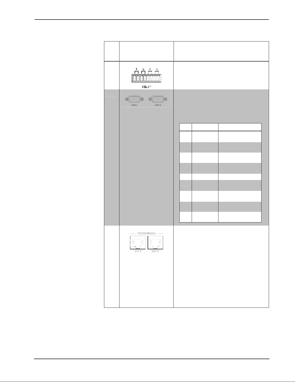
23
24
25
RELAY
COM A & B
TOUCH PANEL OUT
(1) 8-pin 3.5mm detachable terminal block;
Comprises (4) normally open, isolated relays;
Rated 1 Amp, 30 Volts AC/DC;
MOV arc suppression across contacts
(2) DB9 male, bidirectional RS-232 ports;
Up to 115.2k baud, hardware and software
handshaking support for communication with
serial devices. Can also be used for modem
communications. The following table lists the
pin assignments of the serial ports.
PIN DIRECTION DESCRIPTION
1 To
MPS-100
2 To
MPS-100
3 From
MPS-100
4 From
MPS-100
5 Common (GND) Ground
6 To
MPS-100
7 From
MPS-100
8 To
MPS-100
9 To
MPS-100
(DCD) Data Carrier
Detect
(RXD) Receive Data
(TXD) Transmit Data
(DTR) Data Terminal
Ready
(DSR) Data Set
Ready
(RTS) Request To
Send
(CTS) Clear To Send
(RI) Ring Indicator
Contains one CH port and one QM port.
CH Port:
8-wire RJ-45 female; CAT5 balanced video
output port;
Signal Types: Dynamically configurable for
component (Y/Pb/Pr), S-video (Y/C), or
composite video;
Video/HDTV Formats: NTSC or PAL, HDTV up
to 1080i;
Output Impedance: 100 ohms balanced;
Connects to CH CAT5 balanced video input
port of a compatible touchpanel or other
device via CresCAT
®
cable.3
(Continued on following page)
14 • Multimedia Presentation System 100: MPS-100 Operations Guide – DOC. 6527
Crestron MPS-100 Multimedia Presentation System 100
Connectors, Controls & Indicators (Continued)
#
CONNECTORS
CONTROLS &
INDICATORS
1
,
DESCRIPTION
26
TOUCH PANEL OUT
(Continued)
OUTPUT 1
QM Port:
8-wire RJ-45 female; QuickMedia output port;
Signal Types: Dynamically configurable for
RGBHV, component (YP
), S-video (Y/C), or
bPr
composite video with stereo program audio;
RGB Format: RGBHV or RGBS;
RGB Output Resolution, Non-interlaced: 1600
x 1200 maximum (60 Hz limit at 1600 x 1200);
Video/HDTV Formats: NTSC or PAL, HDTV up
to 1080i/1080p;
Connects to QM input port of a compatible
touchpanel or other QuickMedia device via
CresCAT-QM or CresCAT-IM cable.
4
Contains composite, S-video (Y/C),
component (Y, Pb, Pr) and RGBHV outputs on
six BNC connectors and one DB15HD
connector.
Composite Output:
(1) BNC female composite video output
Output Level: 1.0 to 1.1 V
1 V
input)
p-p
(terminated, with
p-p
Output Impedance: 75 ohms nominal
Y/C (S-video):
(2) BNC female; S-video (Y/C) video output
Output Level: 1.0 to 1.1 V
1 V
input);
p-p
(terminated, with
p-p
Output Impedance: 75 ohms nominal
Y/Pb/Pr (component) Output:
(3) BNC female; Component/HDTV (YPbPr)
video output
Output Level: 1.0 to 1.1 V
1 V
input);
p-p
(terminated, with
p-p
Output Impedance: 75 ohms nominal
RGBHV Output:
(1) DB15HD female, RGBHV (VGA) output;
Format: RGBHV or RGBS;
RGB Output Level: 0.7 to 0.75 V
(terminated, with 0.7 V
input, unity gain);
p-p
p-p
RGB Output Impedance: 75 ohms nominal;
Sync Output Level: 4 to 5 V
p-p
;
Sync Output Impedance: 55 ohms;
Sync Polarity: Follows input
(Continued on following page)
Operations Guide – DOC. 6527 Multimedia Presentation System 100: MPS-100 • 15
Multimedia Presentation System 100 Crestron MPS-100
Connectors, Controls & Indicators (Continued)
#
CONNECTORS
CONTROLS &
INDICATORS
1
,
DESCRIPTION
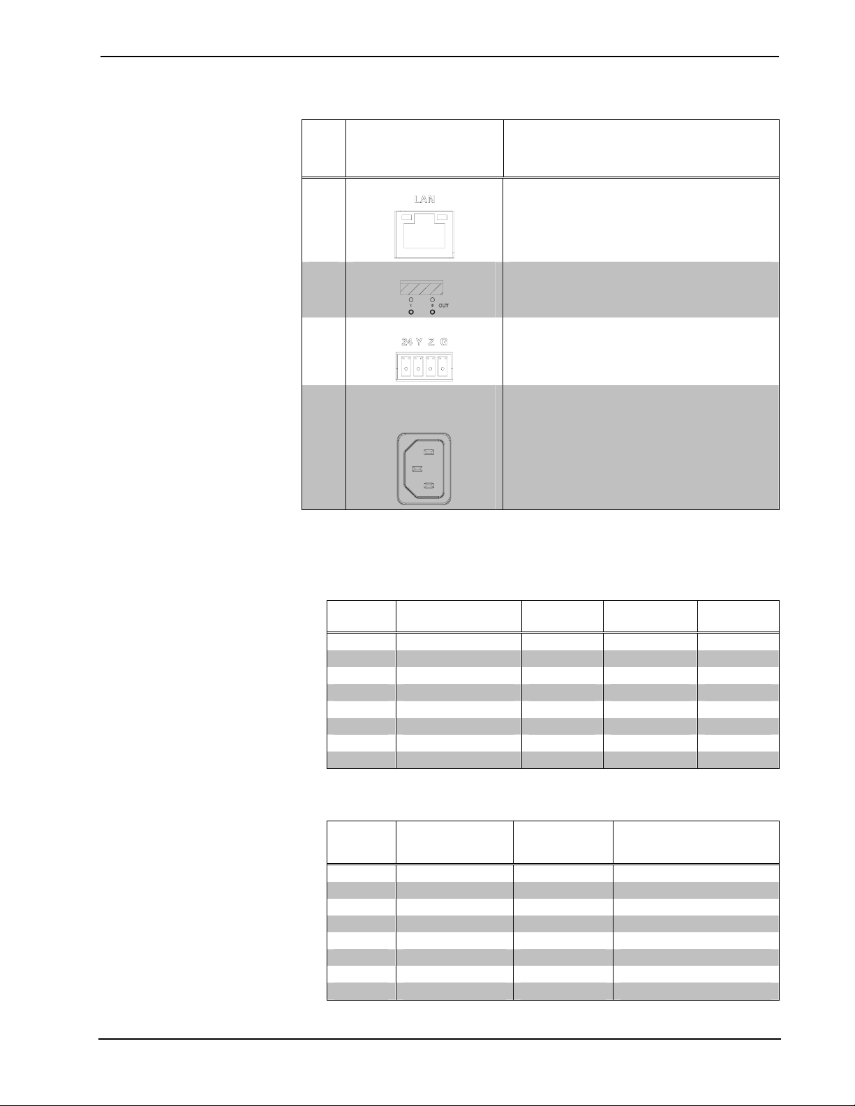
27
LAN
(1) 8-wire RJ45 with 2 LED indicators;
10/100BaseT Ethernet port;
Green LED indicates link status;
Yellow LED indicates Ethernet activity
28
OUTPUT SELECTION (2) pushbuttons and red LEDs, select output
destination
29
NET
(4) 4-pin 3.5mm detachable terminal blocks;
Cresnet Master ports, paralleled;
Available Cresnet Power: 30 Watts
30
100 – 240V ~2.5A
50/60 Hz
(1) IEC Socket, mates with removable power
cord (included).
(POWER SUPPLY)
1. Interface connectors for NET, INFRARED-SERIAL, INPUT, RELAY OUTPUT, and AUDIO
ports are provided with the unit.
2. Transmission levels on the infrared – serial output connectors are in the 0 to +5 VDC range, which
may not be compatible with all RS-232 devices.
3. This eight-pin RJ-45 port provides connectivity to a touchpanel with a CH input port or a Crestron
device with a CAT5 video input. This port provides component, composite or S-video balanced
output over CAT5 wiring. Refer to the following table for connector pinouts.
RJ-45 PIN
NUMBER
1 WHITE/ORANGE + Composite + Luminance + Y
2 ORANGE - Composite - Luminance - Y
3 WHITE/GREEN N/A + Chrominance + Pb
4 BLUE N/A N/A + Pr
5 WHITE/BLUE N/A N/A - Pr
6 GREEN N/A - Chrominance - Pb
7 WHITE/BROWN N/A N/A N/A
8 BROWN N/A N/A N/A
4. The eight-pin RJ-45 QuickMedia transport port accepts CAT5E/CAT6 carrying RGB, audio, video
and microphone signals. The QM port conforms to the 568B wiring standard. Refer to the following
table for connector pinouts.
RJ-45 PIN
NUMBER
1 WHITE/ORANGE - RGB Red - CHROMINANCE (- Pr)
2 ORANGE + RGB Red + CHROMINANCE (+ Pr)
3 WHITE/GREEN - RGB Green - LUMINANCE (- Y)
4 BLUE + Digital Audio + AUDIO
5 WHITE/BLUE - Digital Audio - AUDIO
6 GREEN + RGB Green + LUMINANCE (+ Y)
7 WHITE/BROWN - RGB Blue - COMPOSITE (- Pb)
8 BROWN + RGB Blue + COMPOSITE (+ Pb)
WIRE COLORS (568B) COMPOSITE S-VIDEO COMPONENT
WIRE COLORS
(EIA 568B)
QM
ASSIGNMENT
RGB
QM ASSIGNMENT
COMPOSITE, S-VIDEO,
COMPONENT AND AUDIO
16 • Multimedia Presentation System 100: MPS-100 Operations Guide – DOC. 6527
Crestron MPS-100 Multimedia Presentation System 100
Industry Compliance
This unit has been manufactured to comply with UL’s Standards for Safety in
Canada and the United States. Formal approval is pending.
As of the date of manufacture the MPS-100 has been tested and found to comply
with specifications for CE marking and standards per EMC and
Radiocommunications Compliance Labelling.
NOTE: This device complies with part 15 of the FCC rules. Operation is subject to
the following two conditions: (1) this device may not cause harmful interference and
(2) this device must accept any interference received, including interference that may
cause undesired operation.
This equipment has been tested and found to comply with the limits for a Class B
digital device, pursuant to part 15 of the FCC Rules. These limits are designed to
provide reasonable protection against harmful interference in a residential
installation. This equipment generates, uses and can radiate radio frequency energy
and if not installed and used in accordance with the instructions, may cause harmful
interference to radio communications. However, there is no guarantee that
interference will not occur in a particular installation. If this equipment does cause
harmful interference to radio or television reception, which can be determined by
turning the equipment off and on, the user is encouraged to try to correct the
interference by one or more of the following measures:
Reorient or relocate the receiving antenna.
Increase the separation between the equipment and receiver.
Connect the equipment into an outlet on a circuit different from that to
which the receiver is connected.
Consult the dealer or an experienced radio/TV technician for help.
Operations Guide – DOC. 6527 Multimedia Presentation System 100: MPS-100 • 17
Multimedia Presentation System 100 Crestron MPS-100
Setup
Network Wiring
When wiring the network, consider the following:
• Use Crestron Certified Wire.
• Provide sufficient power to the system.
CAUTION: Insufficient power can lead to unpredictable results or damage
to the equipment. Please use the Crestron Power Calculator to help calculate
how much power is needed for the system
(http://www.crestron.com/calculators
• For larger networks, use a Cresnet Hub/Repeater (CNXHUB) to maintain
signal quality.
For more details, refer to “Check Network Wiring” on page 68.
).
Ethernet
The MPS-100 also uses high-speed Ethernet for communications between the control
system and a device, computer, digital media server and other IP-based devices.
For information on connecting Ethernet devices in a Crestron system, refer to the
latest version of the Crestron e-Control
Reference Guide (Doc. 6052).
CAT5 Wiring
Category 5 (CAT5) wiring is a twisted pair cable designed for Ethernet networks.
These networks operate at speeds of up to 100 Megabits per second (Mbps) using the
100BaseT standard. Crestron takes advantage of this specification for a variety of
video applications.
Crestron recommends using CresCAT, CresCAT-D or CresCAT-Q wiring solutions.
The following chart shows the maximum recommended cable lengths for various
signal formats.
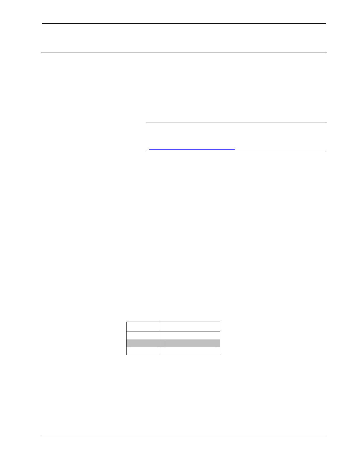
Recommended Maximum Cable Lengths for Video via Crestron Certified Wire
FORMAT MAXIMUM DISTANCE
Composite 500 feet
S-Video 500 feet
Component 500 feet
For more information, refer to the latest version of the Crestron CAT5 Wiring
Reference Guide (Doc. 6137).
QuickMedia Wiring
The Crestron QuickMedia cable (sold under the name “CresCAT-QM”) contains one
CAT5E cable and one Cresnet cable in Siamese jackets. Installation of any QM
device is as simple as installing CresCAT-QM wires from the output of one device to
the input of another. Installations are flexible, affordable and fast. For more
18 • Multimedia Presentation System 100: MPS-100 Operations Guide – DOC. 6527

Crestron MPS-100 Multimedia Presentation System 100
information, refer to the latest revision of the Crestron MediaManager Applications
Guide (Doc. 6244).
CresCAT-QM Cable
NOTE: Do not untwist the two wires in a single pair for more than 1/3-1/2”
(0.84-1.27 cm) when making a connection. The twists are critical to canceling out
interference between the wires.
The aggregate cable length of a signal path originating at the MPS-100 and
terminating at a QM receiver must not exceed 328 feet (100 meters). Video signals
may experience a loss of quality over very long lengths of cable. This phenomenon is
due to the added resistance and capacitance of longer cable lengths and is not
peculiar to either Crestron and/or QuickMedia systems. To ensure sufficient
bandwidth, the maximum aggregate cable length should not exceed 328 feet. The use
of lower-resolution signals may allow increased cable length but must be tested by
the installer with the sources to be used. The QM pin assignment is based on the
EIA/TIA 568B RJ-45 Jack standard.
NOTE: When transmitting S-video, luminance uses the green video pathway and
chrominance uses the red video pathway. When transmitting composite video, the
signal is carried on the blue video pathway.
NOTE: When using CresCAT-QM wiring, four additional wires are included for
making Cresnet connections.
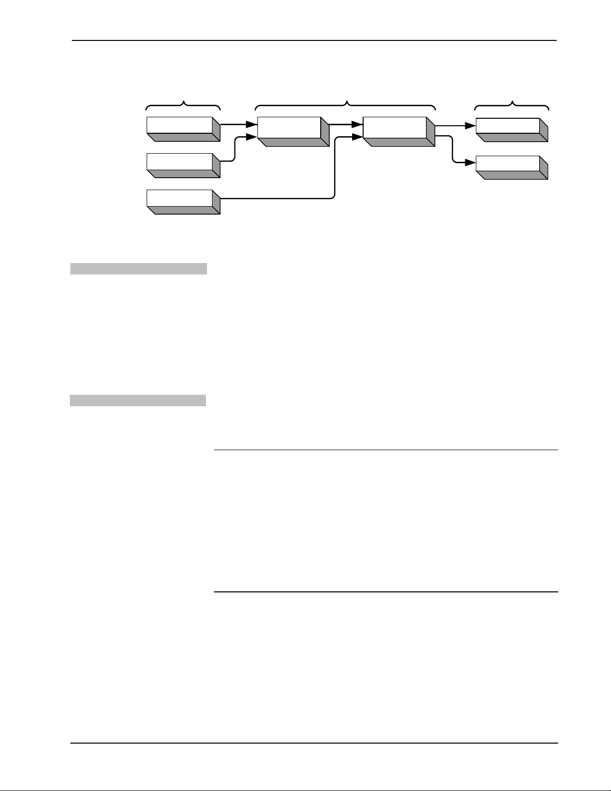
When connecting multiple QM devices, the route between a QM origination point
(transmitter) and a QM endpoint (receiver) cannot have more than two midpoints
(e.g. QM-MD7x2 or other QM switchers). Refer to the following diagram when
configuring a QM network.
NOTE: Use CresCAT-QM to make QM connections. The cumulative skew over the
entire length must be less than 22 ns.
Operations Guide – DOC. 6527 Multimedia Presentation System 100: MPS-100 • 19
Multimedia Presentation System 100 Crestron MPS-100
QM Network Topology
Origination Points Endpoints
Midpoints
Ventilation
Rack Mounting
MPS-100
MPS-100
MPS-100
QM
QM
QM
QM-MD7x2QM-MD7x2
QM
QM
TPS-12G/15G-QM-L
TPS-12G/15G-QM-L
QM
Installation
The MPS-100 should be used in a well-ventilated area. The venting holes should not
be obstructed under any circumstances. If the MPS-100 is hot to the touch, consider
using forced air ventilation and/or incrementing the spacing between units.
To prevent overheating, do not operate this product in an area that exceeds the
environmental temperature range listed in the table of specifications. Consideration
must be given if installed in a closed or multi-unit rack assembly since the operating
ambient temperature of the rack environment may be greater than the room ambient
temperature. Contact with thermal insulating materials should be avoided on all sides
of the unit.
The MPS-100 can be mounted in a rack or stacked with other equipment. Two
“ears” are provided with the MPS-100 so that the unit can be rack mounted. These
ears must be installed prior to mounting. Complete the following procedure to attach
the ears to the unit. The only tool required is a #2 Phillips screwdriver.
WARNING: To prevent bodily injury when mounting or servicing this unit in a
rack, take special precautions to ensure that the system remains stable. The following
guidelines are provided to ensure your safety:
• When mounting this unit in a partially filled rack, load the rack from the
bottom to the top with the heaviest component at the bottom of the rack.
• If the rack is provided with stabilizing devices, install the stabilizers before
mounting or servicing the unit in the rack.
NOTE: Reliable earthing of rack-mounted equipment should be maintained.
Particular attention should be given to supply connections other than direct
connections to the branch circuit (e.g. use of power strips).
To install the ears:
1. There are screws that secure each side of the MPS-100 top cover. Using a
#2 Phillips screwdriver, remove the three screws closest to the front panel
from one side of the unit. Refer to the diagram following step 3 for a
detailed view.
2. Position a rack ear so that its mounting holes align with the holes vacated
by the screws in step 1.
3. Secure the ear to the unit with three screws from step 1, as shown in the
following diagram.
20 • Multimedia Presentation System 100: MPS-100 Operations Guide – DOC. 6527
Loading...