


 Loading...
Crestron QM-RMC
Room Media Controller
Operations Guide

This document was prepared and written by the Technical Documentation department at:
Crestron Electronics, Inc.
15 Volvo Drive
Rockleigh, NJ 07647
1-888-CRESTRON
All brand names, product names and trademarks are the property of their respective owners. ©2003 Crestron Electronics, Inc.
Crestron QM-RMC |
Room Media Controller |
Contents
Room Media Controller: QM-RMC |
1 |
Introduction .......................................................................................................... |
1 |
Features and Functions........................................................................... |
1 |
Specifications ......................................................................................... |
3 |
Physical Description............................................................................... |
4 |
Memory.................................................................................................. |
7 |
Industry Compliance .............................................................................. |
9 |
Setup..................................................................................................................... |
9 |
Hardware Hookup .................................................................................. |
9 |
Establishing Communication with the QM-RMC................................ |
10 |
Troubleshooting Communications ....................................................... |
13 |
Compiling and Uploading a Program to the Control System............... |
15 |
Uploading Web pages to the QM-RMC............................................... |
16 |
Updating the Operating System ........................................................... |
17 |
Advanced Console Commands ............................................................ |
18 |
Programming the QM-RMC............................................................................... |
18 |
Programming with the Crestron AppBuilder ....................................... |
19 |
Programming with SIMPL Windows................................................... |
19 |
Problem Solving ................................................................................................. |
25 |
Troubleshooting ................................................................................... |
25 |
Further Inquiries................................................................................... |
28 |
Firmware Upgrades.............................................................................. |
28 |
Future Updates ..................................................................................... |
28 |
Software License Agreement.............................................................................. |
29 |
Return and Warranty Policies............................................................................. |
31 |
Merchandise Returns / Repair Service ................................................. |
31 |
CRESTRON Limited Warranty ........................................................... |
31 |
Operations Guide – DOC. 6161 |
Contents • i |

Crestron QM-RMC |
Room Media Controller |
Room Media Controller:
QM-RMC
Introduction
Features and Functions
The QM-RMC is a low cost IP management tool to help facilities easily control and monitor A/V devices. This powerful, compact control system enables serial, IR, and Ethernet devices such as projectors, switchers, TVs, and other A/V equipment to be controlled over IP networks. QM-RMC is an ideal solution for colleges, universities, and other multi-room installations. It is a full-scale control system with complete support of all Crestron e-Control® 2 and power applications.
Functional Summary
•Powerful 2-Series processor, based on Motorola’s ColdFire® technology, with non-volatile memory.
•Native e-mail client
•Supports DHCP, DNS and SSL (refer to the notes following this summary).
•Supports XPanel IE/EXE/PDA control (Crestron e-Control®2).
•Programmable logic via SIMPL Windows, including SIMPL+®
•Flash memory and DRAM.
•Two bi-directional COM ports with built-in serial drivers for controlling devices over RS-232.
•One IR port - compatible with Crestron ST-SPL IR-Splitter, for IRControl of up to five different devices, programmable via the hundreds of IR device drivers available in the Crestron databases.
•Four digital input ports for direct connection of power sensors, pressure sensors, door sensors, room occupancy sensor, etc.
•A 10/100 Ethernet LAN port with built-in Web server and support for DHCP; and support for all Crestron e-Control power applications and Crestron RoomView™ A/V facility monitoring and management software.
•When used with Crestron RoomView™, provides remote power control and management of A/V devices, including: monitoring lamp life of projectors, device status to ensure proper equipment operations, room occupancy, equipment use log, and device and room security.
|
|
|
Operations Guide – DOC. 6161 |
Room Media Processor: QM-RMC • 1 |
|

Room Media Controller |
Crestron QM-RMC |
NOTE: DHCP (Dynamic Host Configuration Protocol) is a network protocol that enables a DHCP server to automatically assign an IP address to an individual computer's TCP/IP stack software. DHCP assigns a number dynamically from a defined range of numbers (i.e., a scope) configured for a given network.
NOTE: DNS stands for Domain Name Service (or System). Its primary use is to translate, or resolve, the IP number for a computer (e.g., 129.79.5.208) from an alphanumeric name.
NOTE: SSL, or Secure Socket Layer, is the most commonly used protocol for Web security. In addition to providing security for HTTP (Web hypertext) transactions, SSL works with other TCP/IP standards such as IMAP mail and LDAP directory access. For a security standard such as SSL to work, the browser and the Web server must both be configured to use it.
The QM-RMC is a stand-alone processor with all of the capabilities of a 2- Series processor, without the Cresnet® port. The QM-RMC is programmed with SIMPL Windows and has a built-in web server, native email client, supports DHCP and DNS, as well as SSL (Secure Socket Layer - Industry standard network security native to all Crestron 2-Series control systems). Versatile enough to operate as a standalone control system, the QM-RMC is also ideally suited for integration with an MP2E, MC2E or the CP2E low-cost room control solutions.
The QM-RMC provides a 10/100 Ethernet port with support for DHCP and a built-in Web server, so users can control serial devices from any computer on the LAN, WAN, or even the Internet. Create customized Web pages using Crestron VisionTools® Pro-e software, eliminating the need for third-party Web page design software.
In fact, the new Crestron e-Control® 2 technology gives Web pages the same look and feel as Crestron’s TPS ISYS® touchpanel pages, with almost zero latency. This means you can add multi-mode buttons, gauges, sliders, subpages and high-resolution graphics to your Web page projects, and the runtime performance will be the same as with TPS touchpanels. Crestron e-Control 2 also generates standalone executables allowing users to launch from their Windows® desktop, or Windows XP/Windows, CE StrongARM, XScale, Web Tablet/Handheld PC, or Pocket PC 2002 PDA.
Some applications that QM-RMC can be used to monitor include: remote power control/management of A/V devices, lamp life of projectors, device status to ensure proper equipment operations, room occupancy, and room and/or device security. It can also be used to remotely lock out projector/display controls from unwanted users or to log equipment usage. Combined with the power of Crestron RoomView™ software, hundreds of rooms with QM-RMCs can be centrally monitored as to the status of all the above-mentioned functions by multiple AV-personnel using PC/laptops connected to their LAN/WAN/Internet.
2 • Room Media Processor: QM-RMC |
Operations Guide - DOC. 6161 |
Crestron QM-RMC |
Room Media Controller |
Specifications
Specifications for the QM-RMC are given in the following table.
QM-RMC Specifications
SPECIFICATION |
DETAILS |
|
CPU |
32-Bit Motorola 5272 ColdFire® Processor |
|
Processor Speed |
63 MIPS (Dhrystone 2.1 Benchmark) |
|
Memory |
36MB (4MB flash, 32MB SDRAM, 256KB NVRAM)1 |
|
Ports/Connectors2 |
|
|
LAN |
One – RJ-45 10/100 BaseT Ethernet port |
|
INFRARED – Serial |
One – 2-Position Mini connector IR port (Supports up to five |
|
Input |
IR devices) |
|
INPUT |
One – 5-Position Mini connector (four inputs and GND) |
|
COM (A & B) |
Two – DB9 bidirectional serial ports (RS-232) baud rate up to |
|
|
115,200 bps (Port B is used for initial communication and |
|
|
setup). |
|
12VDC |
One – Male receptacle for external power pack (included) |
|
Reset Buttons |
|
|
HW-R |
Initiates system hardware reset |
|
SW-R |
System restart with or without program |
|
Power Requirements |
6 W (0.5 Amp @ 12 VDC) power supply included |
|
Initial Firmware Release |
3.052 |
|
Environmental |
41° to 113°F (5° to 45°C) |
|
Temperature |
|
|
Environmental Humidity |
10% to 90% RH (non-condensing) |
|
Dimensions & Weight |
Height: |
1.43 in (3.63 cm) |
|
Width: |
4.65 in (11.81 cm) |
|
Depth: |
5.24 in (13.31 cm) |
|
Weight: |
1.34 lb (0.61 kg) |
1.For more information on system memory usage, refer to “Memory” on page 7.
2.For more information on controls, ports, and indicators, refer to “Physical Description” on page 4.
|
|
|
Operations Guide – DOC. 6161 |
Room Media Processor: QM-RMC • 3 |
|

Room Media Controller |
Crestron QM-RMC |
Physical Description
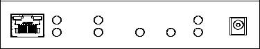
The QM-RMC is housed in a black enclosure with labels on the front and rear panels. On the front of the unit there are six LEDs for indicating the unit’s current status, two LEDs on the LAN connector, and two reset buttons. All connections, except for the Ethernet and power connections, are made on the back of the unit. There are four rubber feet on the base of the unit for stability and to prevent slippage. Refer to the physical views shown below.
Front and Rear Views
Physical Dimensions
4.65 in
(11.81 cm)
1.43 in |
|
|
5.24 in |
(3.63 cm) |
|
|
(13.31 cm) |
|
4 • Room Media Processor: QM-RMC |
Operations Guide - DOC. 6161 |
Crestron QM-RMC |
Room Media Controller |
Controls and Indicators
The QM-RMC front panel indicators and controls are described as follows.
LAN |
|
|
|
12VDC |
|
|
|
0.5A |
|
|
|
|
|
|
COM A |
IR |
HW-R |
SW-R |
PWR |
COM B |
INPUT |
|
|
ACT |
QM-RMC
COM A
LED indicates COM A port activity.
COM B
LED indicates COM B port activity. Constant blinking indicates that the port is used for remote console connection.
IR
LED indicates IR port activity.
INPUT
LED indicates input activity.
HW-R
Pressing this button initiates system hardware reset. (Same effect as disconnecting and reconnecting power.)
SW-R
Pressing this button in combination with the HW-R button performs a system restart without loading the program (refer to “Troubleshooting Communications” on page 13). Press HW-R momentarily while pressing and holding SW-R to reboot.
Pressing SW-R alone while the system is running restarts the program, and puts the unit at a default IP address. COM B port becomes a remote console connection.
PWR (Power)
This green LED illuminates when the unit is connected to and receives 12 VDC power from an external power pack.
ACT (LAN)
This LED illuminates when the QM-RMC communicates with any device on the network.
|
|
|
Operations Guide – DOC. 6161 |
Room Media Processor: QM-RMC • 5 |
|
Room Media Controller |
|
|
|
|
Crestron QM-RMC |
||||||||||||||||||
|
|
|
|
|
|
|
|
|
|
|
|
|
|
Front Panel Ports |
|
|
|
||||||
|
|
|
|
|
|
|
|
|
|
|
|
|
|
The QM-RMC front panel ports are illustrated and described as follows. |
|||||||||
LAN |
|
LAN |
|
|
|
|
|
|
|||||||||||||||
|
An 8-position RJ-45 port (labeled LAN) is used for connection to the Ethernet, |
||||||||||||||||||||||
Yellow |
|
|
|
|
|
|
|
|
|
Green |
|
providing local area network or Web access (cable is not supplied). The port |
|||||||||||
|
|
|
|
|
|
|
|
|
|||||||||||||||
|
|
|
|
|
|
|
|
|
|
|
|
|
|
|
also contains two light-emitting diodes (LEDs). The green LED on the right |
||||||||
|
|
|
|
|
|
|
|
|
|
|
|
|
|
|
side of the port is a link status LED and illuminates when the card is connected |
||||||||
|
|
|
|
|
|
|
|
|
|
|
|
|
|
||||||||||
8 |
|
|
|
|
|
1 |
|
|
|
|
|
|
|
to a working network. The yellow LED on the left side flashes to indicate |
|||||||||
|
|
|
|||||||||||||||||||||
|
|
|
|
|
|
|
|
|
|
|
|
|
|
|
Ethernet activity. Refer to the following table for the Ethernet connector |
||||||||
|
|
|
|
|
|
|
|
|
|
|
|
|
|
|
signals and use an appropriate cable. |
|
|
|
|||||
|
|
|
|
|
|
|
|
|
|
|
|
|
|
|
LAN 8-Position RJ-45 Connector Specifications |
||||||||
|
|
|
|
|
|
|
|
|
|
|
|
|
|
|
|
|
|
|
|
|
|
|
|
|
|
|
|
|
|
|
|
|
|
|
|
|
|
|
|
PIN |
|
SIGNALS |
|
|
PIN 8 |
||
|
|
|
|
|
|
|
|
|
|
|
|
|
|
|
1 |
|
|
TD + |
|
|
|
||
|
|
|
|
|
|
|
|
|
|
|
|
|
|
|
|
|
|
|
|
||||
|
|
|
|
|
|
|
|
|
|
|
|
|
|
|
|
2 |
|
|
TD - |
|
|
|
|
|
|
|
|
|
|
|
|
|
|
|
|
|
|
|
3 |
|
|
RD + |
|
|
|
||
|
|
|
|
|
|
|
|
|
|
|
|
|
|
|
|
|
|
|
|
|
|
||
|
|
|
|
|
|
|
|
|
|
|
|
|
|
|
|
4 |
|
|
Connected to pin 5 |
|
|
|
|
|
|
|
|
|
|
|
|
|
|
|
|
|
|
|
|
|
|
|
|
|
|
||
|
|
|
|
|
|
|
|
|
|
|
|
|
|
|
5 |
|
|
Connected to pin 4 |
PIN 1 |
||||
|
|
|
|
|
|
|
|
|
|
|
|
|
|
|
|
6 |
|
|
RD - |
|
|
|
|
|
|
|
|
|
|
|
|
|
|
|
|
|
|
|
7 |
|
|
Connected to pin 8 |
|
|
|
||
|
|
|
|
|
|
|
|
|
|
|
|
|
|
|
|
|
|
|
|
|
|
||
|
|
|
|
|
|
|
|
|
|
|
|
|
|
|
|
8 |
|
|
Connected to pin 7 |
|
|
|
|
|
|
|
|
|
|
|
|
|
|
|
|
|
|
|
|
|
|
|
|
|
|
|
|
NOTE: To determine the location of pin 1, hold the cable so that the end of the eight pin modular jack is facing away from you, with the clip up and copper side down. Pin 1 is on the far right.
Default Ethernet Ports
80 = Web
41794 = Crestron Com
41795 = Viewport/Debug
12VDC |
12VDC, 0.5A (Power Supply) |
This male connector can be used to supply 12 VDC power to the QM-RMC |
|
0.5A |
from an external power pack (included). |
|
|
|
CAUTION: Use only Crestron power supplies for Crestron equipment. |
|
Failure to do so could cause equipment damage or void the Crestron warranty. |
6 • Room Media Processor: QM-RMC |
Operations Guide - DOC. 6161 |
Crestron QM-RMC |
Room Media Controller |
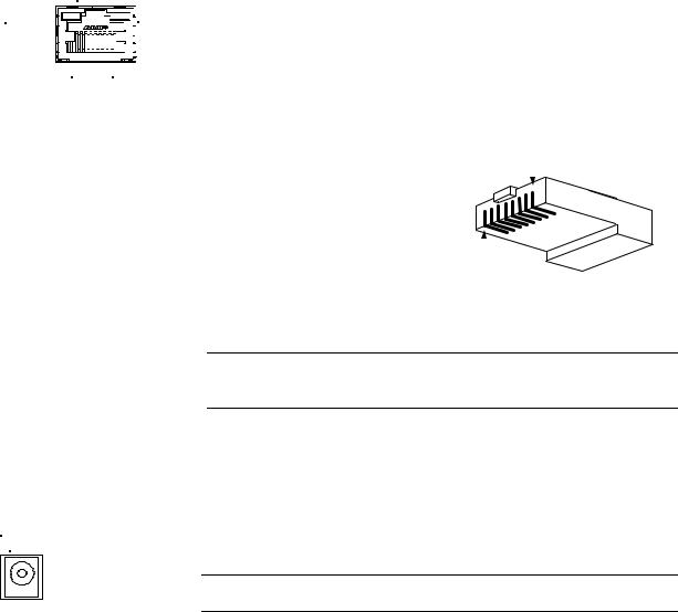
INPUT
1 2 3 4 G
IR
S G
Rear Panel Ports
The QM-RMC rear panel ports are illustrated and described as follows.
INPUT
This connector provides four software programmable digital inputs. Inputs are Schmidt trigger type (nominal 2.5 V threshold) with 24 V input tolerance. For detailed information, refer to “Slot 2: C21-DI04” on page 21.
Digital inputs are rated 0 – 24 VDC, 20K ohms input impedance.
IR
A 2-position mini-connector is a mini-implementation of a single PRO2 IR port. The output is labeled S (signal) and G (ground). Infrared output is rated up to 1.2 MHz, at data rates up to 9600 baud. Serial protocols include oneway RS-232. For detailed information, refer to “Slot 1: C2I-IR1” on page 20.
COM A |
COM B |
COM (A & B)
These two DB9 (male) software programmable, bi-directional serial ports are available for RS-232 communication, with hardware and software handshaking and modem control. Speeds are rated up to 115,200 bps.
COM B is used as the console port.
Standard COM DB9 Pinout
PIN |
DIRECTION |
DESCRIPTION |
|
|
|
1 |
TO QM-RMC |
(DCD) Data Carrier Detect |
2 |
To QM-RMC |
(RXD) Receive Data |
3 |
From QM-RMC |
(TXD) Transmit Data |
|
|
|
4 |
From QM-RMC |
(DTR) Data Terminal Ready |
5 |
Common |
(SG) Signal Ground |
7 |
From QM-RMC |
(RTS) Request To Send |
8 |
To QM-RMC |
(CTS) Clear To Send |
9 |
To QM-RMC |
(RI) Ring Indicator |
Memory
The QM-RMC has 36MB of built-in memory (non-volatile and volatile). The total of 36MB is specified as follows: 4MB flash (non-volatile), 32MB SDRAM (volatile), and 256KB NVRAM (battery backed up). Flash memory contains the file system inside the 2-Series control engine. Non-volatile memory contains information that is retained after the loss of electrical power. Volatile memory is lost after a power failure. Refer to the following lists for a breakdown of memory usage for program-related information stored in the unit.
|
|
|
Operations Guide – DOC. 6161 |
Room Media Processor: QM-RMC • 7 |
|
Loading...