


CREATOR CORPORATION
UUsseer
’
’
Maannuuaall ooff IInntteelllliiggeenntt DDiiggiittaall
ss M
r
CCoonnffeerreennccee SSyysstteem
V2.0
m
CREATOR CHINA

To remind user to conduct according to the attached
operation and maintenance instructions. If ignore these
information, death or injury could possibly happen.
To remind the user that the risky uninsulated voltage in the
device could caused electric shock to human.
CE authentication indicates the product is in line with the
EU safety regulation, and for assurance of safety use.
SGS Authentication indicates the product has reached the
QC standard of the global-biggest Swiss universe
surveyor.
This product has acquired the ISO9001 International
Quality Authentication (Authentication authority: Germany
Rheinland TUV)
Caution: To avoid electric shock, please don't open the
case, nor put the useless parts in it. Please contact with
qualified service staff.
List the situation could cause unsuccessful operation or
setup, and relevant information needed to notice.
Meaning of the Icons
■ Safety Instruction
Symbols are used in the Manual and devices, referring to the possible risk to users or others,as well as
the damage to property, for helping you to safely and properly use the devices. The instruction and the
implications are as follows. Please make sure your correct understanding of these instructions before
using the Manual.
■ General Information Instruction

Important Notices
Caution
To ensure the device in reliable use and
personal safety, please abide by the following
items when in installation, use and maintenance:
Notice in installation
◆ Please DO NOT use the product in following
places: the places with dust, oily smoke,
electrical conductive dust, corrosive gas,
inflammable gas; the places with high
temperature, due, rain and wind exposures; the
places endangered by shock and vibration.
Electric shock, fire and incorrect operation could
also cause damage and deterioration to the
product.
◆ When conducting screw drilling and wiring
process, DO NOT let metal irons and wire lead
drop into the controller and air vent, which could
possibly cause fire, failure and accidental
operation.
◆ After finishing the installation, it is necessary
to ensure there is no foreign matter including the
packing material like contact paper on the
ventilation surface, otherwise, it could cause
poor heat dissipation while running, as well as
fire, failure and accidental operation.
◆ Avoid conducting wiring and plugging in/out
cable socket with electricity, otherwise, electric
shock, circuit damage could easily happen.
◆ Installation and wiring should be firm and
reliable. Poor contact could cause malfunction.
◆ With regard to the application situations with
strong interference, shielded cable should be
used for the input and output of HF signal, to
improve the anti-interference performance of the
system.
Note in Wiring
◆ Installation and wiring shouldn't be conducted
until external electric power is cut off, otherwise,
electric shock or device damage could happen.
◆ The product is grounded by the earth lead of
the power cable. To avoid electric shock, the
earth lead is necessary to be connected with the
ground. Before making connection with the
output end or input end of the product, please
ensure it is correctly grounding.
◆ Upon finish wiring, remove the sundries.
Please cover up the terminal plate for avoiding
electric shock.
Note for Operation and Maintenance
◆ Please DO NOT touch the terminal when with
electricity, otherwise, electric shock could
happen.
◆ Don't clean up and screw the terminal tight
before power is off. Such operation could cause
electric shock when with electricity.
◆ Please turn off the power before connecting or
disconnecting the communication signal cable,
peripheral modules or control units, otherwise,
device could be damaged and accidental
operation could happen.
◆ Please DO NOT disassemble the device, so
as to avoid internal electric components damage.
◆ It is necessary to read through the Manual and
fully ensure the safety, before altering the
program, trial running, starting and stopping
operation.
Note for declaration of worthless.
When declaring of worthless, please note

◆ Explosion of electrolytic capacitor on the
circuit board could happen when burning it.
◆ please classify and dispose it. Don't dispose it
into household garbage.
◆ please deal it as industrial waste, or in
accordance with local environmental protection
regulation.

Preface
User’s Manual of Intelligent Digital Conference System primarily introduce the operation of
CR-M4101,CR-M4201,CR-ME4000,CR-M4104A1,CR-M4102A2,CR-M4104A2,CR-M4202A2,CR-M42
04A2,CR-M4102B,CR-M4104B,CR-M4202B2,CR-M4204B2,CR-M4202G,CR-M4204G,CR-M4102C1,
CR-M4104C1,CR-M4102C4,CR-M4104C4,CR-M4102D2,CR-M4104D2,CR-TP4104D,CR-M4102E,C
R-M4104E,CR-M4102F,CR-M4104F,CR-MC4032B,CR-MC4034B,CR-M4103E3,CR-TP4102,CR-IR20
00-12,CR-IR2001-12,CR-IR2002-12,CR-V101*, MVC-4200, CR-T1000, key parameters and trouble
shootings.
The Manual serves as user's operation instruction, rather than for maintenance service purpose.
Since the date of release, any function or relevant parameter alteration will be in supplement instruction.
Please refer to the manufacturer or dealers for inquiry.
CREATOR Electronics own the copyright of the Manual. Without permission, any unit or person
shall not take part or total of the Manual for business purpose.
The copyright of the Manual is protected by Copyright Law of People’s Republic of China and other
Intellectual Property Law. Without written permission, any copy or distribution is prohibited.

Index
Chapter 1 Overview ................................................................................................................................... 1
1.1 System Features ........................................................................................................................... 1
1.2 System Devices ............................................................................................................................ 2
1.3 Controller Installation .................................................................................................................... 2
Chapter 2 DCS Control System ................................................................................................................ 3
2.1 Conference Controlling Controller ................................................................................................ 3
2.1.1 Panel Functions Instruction............................................................................................. 3
2.1.2 Functions and Features .................................................................................................. 5
2.1.3 Port Pin Instruction .......................................................................................................... 5
2.2 Conference Extended Controller .................................................................................................. 6
2.2.1 Panel Functions Instruction............................................................................................. 6
2.2.2 Functions and Features .................................................................................................. 7
2.3 ID Setup in Conference Unit ......................................................................................................... 7
2.4 System Connection Diagram ........................................................................................................ 7
2.5 Technical Parameters ................................................................................................................... 8
Chapter 3 DCS Discussion Unit ................................................................................................................ 9
3.1 Type of DCS Discussion Unit ........................................................................................................ 9
3.2 CR-M4104A1 Discussion Unit .................................................................................................... 10
3.2.1 Panel Functions Instruction........................................................................................... 10
3.2.2 Functions and Features ................................................................................................ 10
3.3 CR-M4102/4A2 Chairman/Delegate Unit ................................................................................... 11
3.3.1 Panel Functions Instruction........................................................................................... 11
3.3.2 Functions and Features ................................................................................................ 12
3.4 CR-M4202/4A2 Chairman/Delegate Unit ................................................................................... 12
3.4.1 Panel Functions Instruction........................................................................................... 12
3.4.2 Functions and Features ................................................................................................ 13
3.5 CR-M4102/4B Chairman/Delegate Unit ..................................................................................... 14
3.5.1 Panel Functions Instruction........................................................................................... 14
3.5.2 Functions and Features ................................................................................................ 14
3.6 CR-M4202/4B2 Chairman/Delegate Unit ................................................................................... 15
3.6.1 Panel Functions Instruction........................................................................................... 15
3.6.2 Functions and Features ................................................................................................ 16
3.7 CR-M4202/4G Chairman/Delegate Unit ..................................................................................... 17

3.7.1 Panel Functions Instruction........................................................................................... 17
3.7.2 Functions and Features ................................................................................................ 18
3.8 Embedded Unit ........................................................................................................................... 18
3.8.1 Panel Functions Instruction........................................................................................... 18
3.8.2 Functions and Features ................................................................................................ 19
3.9 CR-M4102/4D2 Chairman/Delegate Unit ................................................................................... 20
3.9.1 Panel Functions Instruction........................................................................................... 20
3.9.2 Functions and Features ................................................................................................ 21
3.10 CR-TP4102D Chairman Unit .................................................................................................... 22
3.10.1 Panel Functions Instruction......................................................................................... 22
3.10.2 Touch Screen Functions Instruction ............................................................................ 23
3.10.3 Functions and Features .............................................................................................. 25
3.11 CR-TP4102D Chairman Unit..................................................................................................... 26
3.11.1 Panel Functions Instruction ......................................................................................... 26
3.11.2 Functions and Features .............................................................................................. 27
3.12 CR-M4102/4F Chairman/Delegate Unit .................................................................................... 27
3.12.1 Panel Functions Instruction......................................................................................... 27
3.12.2 Functions and Features .............................................................................................. 28
3.13 Connection Diagram ................................................................................................................. 29
3.13.1 Diagram of T-shaped Connection Mode ..................................................................... 29
3.13.2 Diagram of Hand-in-hand Connection Mode .............................................................. 29
3.13.3 Diagram of Embedded Unit Connection ..................................................................... 29
3.14 Technical Parameters ............................................................................................................... 30
Chapter 4 DCS Simultaneous Interpretation ........................................................................................... 32
4.1 CR-M4103E3 Interpretation Unit ................................................................................................ 32
4.1.1 Panel Functions Instruction........................................................................................... 32
4.1.2 Monitor Description ....................................................................................................... 33
4.1.3 Menu Setup ................................................................................................................... 33
4.1.4 Monitoring Unit .............................................................................................................. 35
4.1.5 Functions and Features ................................................................................................ 35
4.2 Technical Parameters ................................................................................................................. 36
4.3 Diagram of System Connection .................................................................................................. 37
Chapter 5 DCS Infrared Voice Distribution System ................................................................................ 38
5.1 Products and Devices ................................................................................................................. 38
5.2 CR-IR2000-12 Infrared Transmission Controller ........................................................................ 38
5.2.1 Panel Functions Instruction........................................................................................... 38
5.2.2 Functions and Features ................................................................................................ 39
5.2.3 Technical Parameters ................................................................................................... 39
5.3 CR-IR2001-12 Infrared Radiation Panel ..................................................................................... 39

5.3.1 Panel Functions Instruction........................................................................................... 39
5.3.2 Functions and Features ................................................................................................ 40
5.3.3 Technical Parameters ................................................................................................... 40
5.4 CR-IR2002-8/12 Infrared Receiving Unit .................................................................................... 40
5.4.1 Panel Functions Instruction........................................................................................... 40
5.4.2 Functions and Features ................................................................................................ 40
5.4.3 Technical Parameters ................................................................................................... 41
5.5 Diagram of System Connection .................................................................................................. 41
hapter 6 DCS Camera Tracing ................................................................................................................ 42
6.1 Products and Devices ................................................................................................................. 42
6.2 MVC-4200 Camera Tracing Mixing Controller ............................................................................ 42
6.2.1 Panel Functions Instruction........................................................................................... 42
6.2.2 Functions and Features ................................................................................................ 43
6.2.3 Technical Parameters ................................................................................................... 43
6.3 CR-V1011/V1012 High-speed Camera....................................................................................... 43
6.3.1 Functions and Features ................................................................................................ 43
6.3.2 Technical Parameters ................................................................................................... 44
6.4 Diagram of System Connection .................................................................................................. 45
Chapter 7 DCS Telephone Conference .................................................................................................. 46
7.1 Product s and Devices ................................................................................................................ 46
7.2 CR-T1000Panel Functions Instruction ........................................................................................ 46
7.3 Functions and Features .............................................................................................................. 46
7.4 Technical Parameters ................................................................................................................. 47
7.5 Diagram of System Connection .................................................................................................. 47
Chapter 8 Accessories ............................................................................................................................ 48
8.1 CR-P2 Headset(Without MIC) ............................................................................................. 48
8.1.1 Product Profile ............................................................................................................... 48
8.1.2 Technical Parameters ................................................................................................... 48
8.2 CR-P4 Headset with MIC ............................................................................................................ 48
8.2.1 Product profile ............................................................................................................... 48
8.2.2 Technical Parameters ................................................................................................... 48
8.3 Cable Installation ......................................................................................................................... 48
8.4 CR-M5KL415 Turning 415mm MIC Stand .................................................................................. 49
8.5 CR-CT10 T-shaped Connector ................................................................................................... 49
8.6 CR-CT20 Conference Desktop Socket ....................................................................................... 49
8.7 CR-CT30 Jumping Conference Socket ...................................................................................... 49

8.8 CR-CT50 8-pin Aviation Connector ............................................................................................ 49
8.9 CR-HMP24 Extended Power Supply .......................................................................................... 49
8.10 CR-link20 Signal Amplifier ........................................................................................................ 50
Chapter 9 Annex ...................................................................................................................................... 51
9.1 Code Specification ...................................................................................................................... 51

1
User’s Manual of Intelligent Digital Conference System
Chapter 1 Overview
CREATOR intelligent digital conference
system is a high-tech professional products
series after the launch of multimedia central
control products and audio and video matrix
products, including discussion and Discussion,
simultaneously interpretation, infrared voice
distribution, remote telephone conference, voting,
camera tracing etc.
Inherited with the idea of complete system
integrating resolution as CREATOR has been
advocating all along, CREATOR making close
compatibility between two different system of
DCS (digital conference system) and MCS
(multimedia central system), delivering an
complete intelligent conference system resolution
comprising of CREATOR products.
This Manual is made for the controlling
controller of CREATOR intelligent digital
conference system, Discussion unit, camera
tracking system, telephone conference system
and infrared voice distribution system.
1.1 System Features
◆ Security
For any conference, the priority is to ensure
the security of every delegate presented.
1) Conference unit adopt passive device,
with power supply from the controller;
2) All parts are adopted with the materials
with security certificate ;
3) Anti-static.
◆ Anti-interference
In communication and application system,
unique technical processing is adopted, for
preventing from external radiation interference.
◆ Complete Function
Intelligent digital conference system
integrates with discussion, voting, simultaneously
interpretation as a whole. Press the keys on the
unit to choose conference discussion, conference
voting and voice channel.
◆ Clear Voice Transportation
Adopting quality sound pick-up, built-in
speaker, high-fidelity speaker for ensuring to have
clear transportation and receiving when each
delegate is giving a Discussion.
◆ Reliable Encryption System
Adopting unique secure encryption measure
to ensure the privacy of the conference and the
content of the whole conference won’t be leaked
or tapped malignantly.
◆ Good for Maintenance, Easy Operation
1) The whole conference system is easy for
operation. The system is connected in the way of
hand-in-hand or T-shaped. The installation is very
simple. In conference, participant may just press
on the Discussion key to give a Discussion, with
adjustable volume.
2) After taking short-term training, user can
maintain the system, without very professional
technique needed.
◆ Extendibility
As the number of participants of the
conference vary, the extendibility of the
conference system becomes increasingly
important. CREATOR intelligent conference
system is with simple and reasonable structure,
and strong extendibility.
◆ Various Options
CREATOR intelligent digital conference
system may opt to different conference system
according to different occasions and needs,
CREATOR CHINA 2010-09 WWW.CREATOR1997.COM

2
User’s Manual of Intelligent Digital Conference System
including discussion conference, digital voting
conference system, simultaneous interpretation
system, camera tracing conference system,
telephone conference system etc.
1.2 System Devices
CREATOR intelligent digital conference
system comprises of the following devices:
◆ DCS Control System
Conference Control Controller
CR-M4101、CR-M4201
Conference Extended Controller
CR-ME4000
◆ DCS Discussion Unit
Conference Chairman Unit
CR-M4102A2 、 CR-M4202A2 、 CR-M4102B 、
CR-M4202B2 、 CR-M4202G 、 CR-M4102C1、
CR-M4102C4、 CR-M4102D2、 CR-TP4102D、
CR-M4102E、CR-M4102F
Conference Delegate Unit
CR-M4104A1、CR-M4104A2、CR-M4204A2、
CR-M4104B、CR-M4204B2、CR-M4204G、
CR-M4104C1、 CR-M4104C4、CR-M4104D2、
CR-M4104E、CR-M4104F
Audio Cabinet
CR-MC4032B、CR-MC4034B
◆ DCS Simultaneous Interpretation
CR-M4103E3
◆ Infrared Voice Distribution System
Infrared Transmission Controller
CR-IR2000-12
Infrared Radiation Panel
CR-IR2001-12
Infrared Receiving Unit
CR-IR2002-12
◆ DCS Camera Tracing
Camera tracing mixed controller
MVC- 4200
High-speed Camera
CR-V1011、V1012
◆ DCS Telephone Conference
Telephone Coupler
CR-T1000
◆ DCS Relevant Accessories
Headset
CR-P2、CR-P4
Cable
CR-HL005、CR-HL010、CR-HL020、CR-HL050 、
CR-HL100、CR-HT002、CR-HT005
Other Accessories
CR-M5KL415 Turning MIC stand, CR-CT10
T-shaped connector, CR-CT20 conference
desktop socket, CR-CT30 jumping conference
socket、CR-CT50 8-pin aviation plug、CR-HMP24
extending power supply 、 CR-link20 signal
amplifier
1.3 Controller Installation
The controlling controller of CREATOR
intelligent digital conference system can be
installed into a standard 19-inch cabinet. The
controller is with accessory of a pair of cabinet
installation supports. Please see the following
picture for installation:
CREATOR CHINA 2010-09 WWW.CREATOR1997.COM

3
User’s Manual of Intelligent Digital Conference System
Chapter 2 DCS Control System
2.1 Conference Controlling
Controller
The controlling controller of intelligent digital
conference is an important bridge over
conference units and PC management. Using the
navigation keyboard on the panel, along with the
conference management function of the software,
you may have centralized control on all
conference functions, with a variety of conference
mode options (delegate number option,
Discussion mode option), super extending
function, DSP audio processing, equalizer
module, environmental noise suppressing
technology.
2.1.1 Panel Functions Instruction
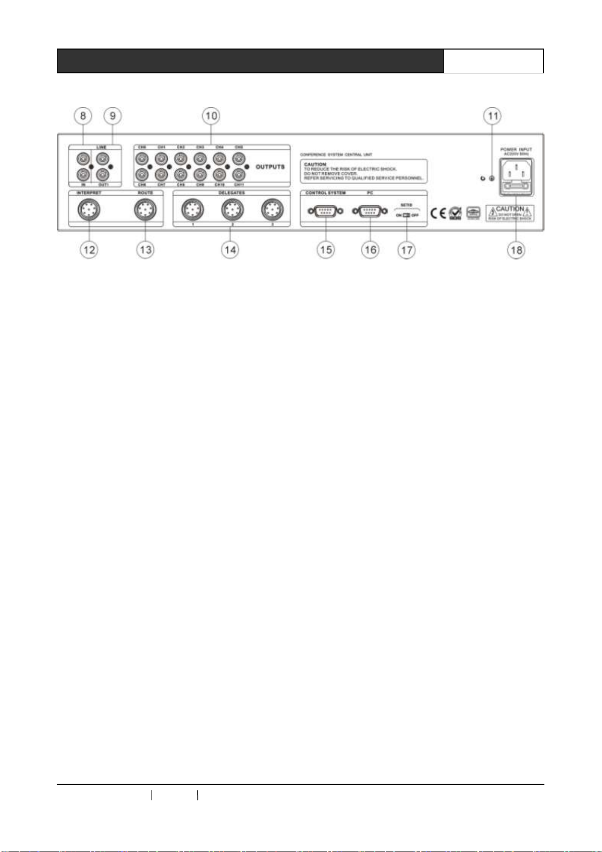
CR-M4101 Front Panel:
CR-M4201 Front Panel:
CREATOR CHINA 2010-09 WWW.CREATOR1997.COM
4
User’s Manual of Intelligent Digital Conference System
CR-M4101/CR-M4201 Rear Panel:
1) Power Switch
2) MODE
FIFO mode, after reaching the number to
turn on the unit, the earlier-turned-on unit will be
shut down by the unit turned on later.
NORMAL mode,after reaching the number to
turn on the unit, the delegate with request to give
a Discussion will be automatically queue up.
FREE mode, allowing 20 delegate units
online at the same time, without limitation from
the controller. If a delegate request to give a
Discussion, he will automatically queue up
APPLY mode,delegate unit cannot give a
Discussion before getting the approval from
chairman unit or operator.
3) ACTIVE MICRO’S —— Number of speaker
limitation, the delegate units online at the same
time can be set as 1/2/4/6.
4) Audio Effect Setup
A:AFC anti-feedback function setup, press
the AFC key on controller panel to activate
anti-feedback function, at the meantime, the
indicator of the key will be on. Press AFC key
again to turn off the indicator, and shut down
anti-feedback function.
B: ANC noise suppression function setup,
AGC MIC auto-gain control function setup is
operated in the same way as AGC
5) BASS —— Output bass volume adjustment
6) TREBLE——Output treble volume
adjustment.
7) VOLUME ——Output volume adjustment.
8 ) IN ——Cable audio input, such as
background music or remote telephone
conference terminal output
9) OUT ——Connect to audio amplifying system
or recording device, including conference audio
and cable input audio.
10) OUTPUTS ——11+1 channels audio output,
connecting to infrared transmission controller.
11) Connect to grounding pole.
12) INTERPRET ——Connect to 36 interpreter
units at maximum, realizing 11+1 languages
simultaneous interpretation. Interpreter units are
connected hand-in-hand.
13) ROUTE ——Connect to extended controller,
with hand-in-hand serial connections within
CREATOR CHINA 2010-09 WWW.CREATOR1997.COM
5
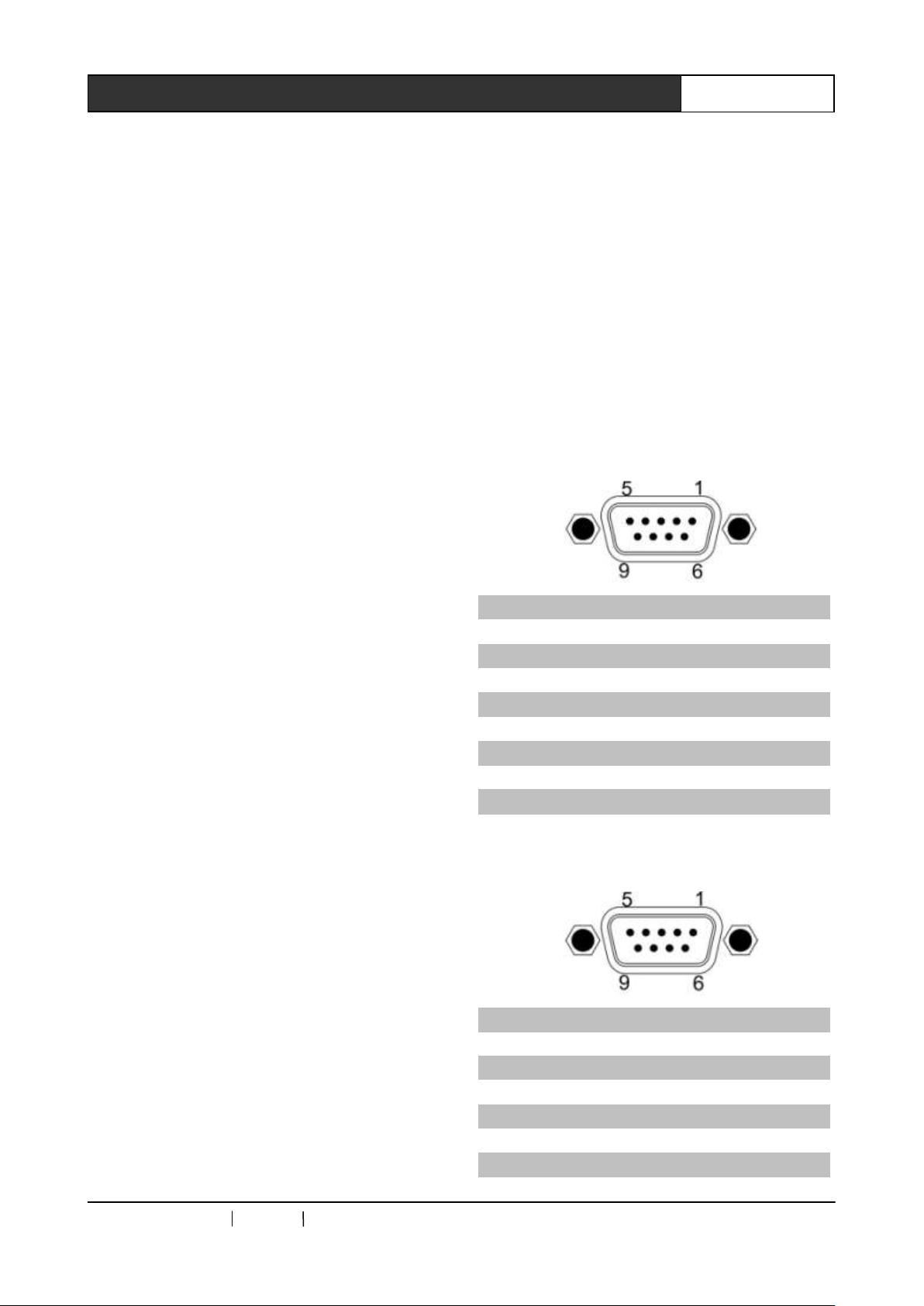
User’s Manual of Intelligent Digital Conference System
Pin
Signal
Instruction
1 — —
2 — —
3
TXD
Data transmission
4 — —
5
GND
Signal ground
6 — —
7 — —
8 — —
9 — —
Pin
Signal
Instruction
1 — —
2
TXD
Data transmission
3
RXD
Data receiving
4 — —
5
GND
Signal ground
6 — —
multiple extended controllers.
14) DELEGATES —— Connect to Discussion
unit。
15) CONTROL SYSTEM ——connect to
controller of central controlling system or camera
tracing controller, realize auto-camera and tracing
function.
16) PC ——Connect to PC serial port, realize
conference management function via software.
17) SET ID ——ID setup of Conference unit
18) POWER INPUT ——Power input, support
AC110V/220V
2.1.2 Functions and Features
◆ Conference controlling controller can connect
up to 128 conference units, via conference
extended controller, a set of conference system
can connect to 4096 conference units at
maximum.
◆ Connect to 36 interpreter units at maximum,
realizing the function of 11+1 languages
simultaneous interpretation;
◆ Adopt special 8-pin aviation plug;
◆ Hand-in-hand or T-shaped connection mode;
◆ With audio input port;
◆ With multiple original audio channels output;
◆ Number of speakers limitation; Adjustable
number of 1/2/4/6 for speaking units. Chairman
unit is not limited.
◆ Support a variety of conference modes of FIFO,
NORMAL, FREE and APPLY.
◆ Support auto-camera tracing function;
◆ Hold remote telephone conference along with
telephone coupler;
◆ Support sign-up, voting and data management
function;
◆ The controller can be installed into a standard
19-inch cabinet.
2.1.3 Port Pin Instruction
2.1.3.1 Pin instruction to CONTROL SYSTEM
COM
2.1.3.2 PC COM pin instruction
CREATOR CHINA 2010-09 WWW.CREATOR1997.COM

6
User’s Manual of Intelligent Digital Conference System
7 — —
8 — —
9 — —
2.2 Conference Extended
Controller
CR-ME4000 Conference system extended
controller supports hand-in-hand serial
connection within multiple extended controllers.
2.2.1 Panel Functions Instruction
CR-ME4000 Front Panel:
CR-ME4000 Rear Panel:
1) POWER —— Power switch
2) ACTIVE ——Working indicator
3) NETWORK ——Network indicator
4 ) COMMUNICATION ——communication
indicator
5) ID ——For configuring the network ID of
ME4000.
6) DELEGATES ——3-way Discussion units
port.
7) ROUTE ——Cascade connection port. A for
connecting to preamp device and B for
CREATOR CHINA 2010-09 WWW.CREATOR1997.COM

7
User’s Manual of Intelligent Digital Conference System
connecting to amp device.
8) Connect to grounding pole
9 ) POWER INPUT——Power input, support
AC110V/220V.
2.2.2 Functions and Features
◆ Adopt 8-pin aviation plug for connection;
◆ Connect to Discussion unit along with the
AUX of conference controlling controller;
◆ Undertaken high-pressure (3500V) test;in
accordance with safety standard;
◆ The controller adopts metal shell, with 8000V
anti-static power;
◆ The controller can be installed into a 19-inch
standard cabinet.
2.3 ID Setup in Conference Unit
1、Conference ID setting is to allocate a unique
address for each conference unit (including
interpreter unit and Discussion unit) to be
identified by the controller.
2、 Conference unit is configured in the following
way: after finishing connecting the conference
system, turn on the power of conference
controller, and turn ―SET ID‖ switch to ―ON‖, and
turn on the Discussion units and interpreter units,
indicator on MIC will be on. After all conference
units are opened, turn ―SET ID‖ switch to ―OFF‖,
all MIC indicators of conference units will be off,
and the system accesses to normal status in use.
2.4 System Connection Diagram
CREATOR CHINA 2010-09 WWW.CREATOR1997.COM

8
User’s Manual of Intelligent Digital Conference System
Parameters
CR-M4101
CR-M4201
CR-ME4000
Power
Switch power 110V / 220V
Switch power 110V / 220V
Switch power 110V / 220V
Static power
consumption
10W
10W
10W
Max power
350W
350W
350W
Output power
≤110W/24V each way
≤110W/24V each way
≤110W/24V each way
Audio output
Impedance : 100Ω way :
non-balanced audio effect:
N/A
Impedance: 100Ω way :
non-balanced audio effect:
support audio effect setup
Impedance: 100Ω way :
non-balanced
MIC input
Impedance:100kΩ
LEV:-60 dB
Way:Non-balanced
Impedance:100kΩ
LEV:-60 dB
Way:Non-balanced
Impedance:100kΩ
LEV:-60 dB
Way:Non-balanced
Frequency
response
60-8kHz
60-8kHz
60-8kHz
S/N
>80dB
> 80dB
> 80dB
THD
< 0.5%
< 0.5%
< 0.5%
Carrier distortion
<1%
<1%
<1%
Cross talk
attenuation(1kHz)
>50dB
>50dB
>50dB
Weight
About 6.5KG
About 6KG
About 6KG
Dimension
483L x 275W x88H (mm)
483L x 275W x88H (mm)
483L x 275W x88H (mm)
Color
Grey
Grey
Grey
2.5 Technical Parameters
CREATOR CHINA 2010-09 WWW.CREATOR1997.COM

9
User’s Manual of Intelligent Digital Conference System
Model
Name
Shape
MIC Key
Voting
Channel
Switch
LCD
Monitor
VFD
Monitor
CR-M4104A1
Delegate
Discussion
unit
Flipping
Yes
N/A
N/A
N/A
N/A
CR-M4102A2
Chairman unit
Flipping
Yes
Yes
N/A
Yes
N/A
CR-M4104A2
Delegate unit
Flipping
Yes
Yes
N/A
N/A
N/A
CR-M4202A2
Chairman unit
Flipping
Yes
Yes
N/A
Yes
N/A
CR-M4204A2
Delegate unit
Flipping
Yes
Yes
N/A
Yes
N/A
CR-M4102B
Chairman
Discussion
unit
Desktop
Yes
N/A
N/A
N/A
N/A
CR-M4104B
Delegate
Discussion
unit
Desktop
Yes
N/A
N/A
N/A
N/A
CR-M4202B2
Chairman
Discussion
unit
Desktop
Yes
Yes
N/A
Yes
Yes
CR-M4204B2
Delegate
Discussion
unit
Desktop
Yes
Yes
N/A
Yes
Yes
CR-M4202G
Chairman
Discussion
unit
Desktop
Yes
N/A
N/A
N/A
N/A
CR-M4204G
Delegate
Discussion
unit
Desktop
Yes
N/A
N/A
N/A
N/A
CR-M4102C1
Chairman
Discussion
unit
Embedd
ed
Yes
N/A
N/A
N/A
N/A
CR-M4104C1
Delegate
Discussion
unit
Embedd
ed
Yes
N/A
N/A
N/A
N/A
CR-M4102C4
Chairman
voting unit
Embedd
ed
N/A
Yes
N/A
N/A
N/A
CR-M4104C4
Delegate
voting unit
Embedd
ed
N/A
Yes
N/A
N/A
N/A
Chapter 3 DCS Discussion Unit
3.1 Type of DCS Discussion Unit
CREATOR CHINA 2010-09 WWW.CREATOR1997.COM

10
User’s Manual of Intelligent Digital Conference System
CR-M4102D2
Chairman unit
Pulling
Yes
Yes
N/A
Yes
N/A
CR-M4104D2
Delegate unit
Pulling
Yes
Yes
N/A
Yes
N/A
CR-TP4102D
Chairman unit
Pulling
Yes
Yes
N/A
Yes
N/A
CR-M4102E
Chairman
Discussion
unit
Desktop
Yes
N/A
N/A
N/A
N/A
CR-M4104E
Delegate
Discussion
unit
Desktop
Yes
N/A
N/A
N/A
N/A
CR-M4102F
Chairman unit
Embedd
ed
Yes
Yes
N/A
Yes
N/A
CR-M4104F
Delegate unit
Embedd
ed
Yes
Yes
N/A
Yes
N/A
CR-MC4032B
Chairman
dual-audio
cabinet
N/A
N/A
N/A
N/A
N/A
CR-MC4034B
Delegate
dual-audio
cabinet
N/A
N/A
N/A
N/A
N/A
3.2 CR-M4104A1 Discussion Unit
3.2.1 Panel Functions Instruction
CR-M4104A1 Front view Side view
① MIC port
② MIC switch
③ Panel speaker
④ Headset port
⑤ Volume adjustment knob
3.2.2 Functions and Features
◆ Pure discussion flipping delegate unit;
◆ Adopts especial 8-pin high-intensity aviation
plug;
◆ Heart-shaped directional condenser pickup,
with dual-color indicator, as red for Discussion
and green for applying for Discussion;
◆ Adopt turning plugging MIC stand;
◆ With connection cable with length of 2
meters;
◆ With inside magnetic speaker, headset port
and volume adjustment knob;
◆ The units are passive devices, and with 24V
power supply from the system controller;
CREATOR CHINA 2010-09 WWW.CREATOR1997.COM

11
User’s Manual of Intelligent Digital Conference System
◆ With anti-feedback function, when the MIC is
on, the speaker of the device will be automatically
shut down, so as to prevent from audio feedback.
◆ T-shaped connecting mode
3.3 CR-M4102/4A2
Chairman/Delegate Unit
3.3.1 Panel Functions Instruction
CR-M4102A2 Front view Side view
——Conference assessment, with numbers 1 to 5
representing grades of --,- ,0,+ ,++
respectively.
Press and hold chairman unit digit key ―1‖
for 3 second to initiate voting and access to voting
status. The last vote is valid. Discussion unit is
with memory for last voting press. Voting result
will be shown by indicator. Press and hold
chairman unit digit key ―5‖ for 3 second to stop
voting, press and hold key ―5‖ to return to
conference mode.
Privilege function:
Shut down——Press and hold chairman unit
MIC switch for 3 seconds to shut down all opened
delegate Discussion units.
CR-M4104A2 Front panel Side panel
① MIC port。
② Multi-functional voting key:
——Conference voting, number 2,3,4 are
respectively for in favor, abstaining and objection
——Conference election, with numbers 1 to 5
representing different candidates.
Pre-conference sign-up:
Press and hold chairman digit key ―2‖ for 3
seconds to initiate sign-up and access to sign-up
mode, press ―MIC switch‖ key to sign up.
Press chairman unit key ―5‖ for 3 seconds to exit
sign-up mode.
Processing Discussion application:
Press chairman unit digit key ―3‖ to approve
Discussion application. Pressing it once to
approve one delegate unit for giving a Discussion
and in according with the principle of ―first come
first out‖.
③ LCD monitor
④ MIC switch
⑤ Flat panel speaker
⑥ Headset port
⑦ Volume adjustment knob
CREATOR CHINA 2010-09 WWW.CREATOR1997.COM

12
User’s Manual of Intelligent Digital Conference System
3.3.2 Functions and Features
◆ Incorporated with the functions of giving
Discussion, voting, pressing sign-up as a whole;
◆ Adopt special 8-pin high-intensity aviation
connector;
◆ Heart-shaped directional condenser pickup,
with dual-color indicator, as red for Discussion
and green for applying for Discussion;
◆ With connection cable with length of 2
meters;
◆ Adopt turning plug MIC stand;
◆ With inside magnetic speaker, headset port
and volume adjustment knob;
◆ Chairman unit is entitled to approve delegate’s
application for Discussion;
◆ Chairman unit is not limited by the number of
speakers;
◆ Chairman unit has privilege to control the
whole conference order.;
◆ Connection position of the chairman unit is not
restricted;
◆ The units are passive devices and with 24V
power supply from the system controller;
◆ With feedback suppression, when turning on
the MIC, the speaker of the device will be
automatically turned off, so as to prevent from
feedback;
◆ Hand-in-hand or T-shaped connection mode.
3.4 CR-M4202/4A2
Chairman/Delegate Unit
3.4.1 Panel Functions Instruction
CR-M4202A2 Front view:
CR-M4204A2 Front view:
Unit side view:
① MIC port。
② Multi-functional voting key:
——Conference voting, number 2,3,4 are
CREATOR CHINA 2010-09 WWW.CREATOR1997.COM

13
User’s Manual of Intelligent Digital Conference System
respectively for in favor, abstaining and objection
——Conference election, with numbers 1 to 5
representing different candidates.
——Conference assessment, with numbers 1 to 5
representing grades of --, - ,0, + , ++
respectively.
Press and hold chairman unit digit key ―1‖
for 3 second to initiate voting and access to voting
status. The last vote is valid. Discussion unit is
with memory for last voting press. Voting result
will be shown by indicator. Press and hold
chairman unit digit key ―5‖ for 3 second to stop
voting, press and hold key ―5‖ to return to
conference mode.
Privilege function:
Shut down——Press and hold chairman unit
MIC switch for 3 seconds to shut down all opened
delegate Discussion units.
Pre-conference sign-up:
Press and hold chairman digit key ―2‖ for 3
seconds to initiate sign-up and access to sign-up
mode, press ―MIC switch‖ key to sign up.
Press chairman unit key ―5‖ for 3 seconds to exit
sign-up mode.
Processing Discussion application:
Press chairman unit digit key ―3‖ to approve
Discussion application. Pressing it once to
approve one delegate unit for giving a Discussion
and it is in according with the principle of ―first
come first out‖.
③ Speaker
④ LCD monitor
⑤ MIC switch
⑥ Privilege switch of chairman unit
⑦ Headset port
⑧ Volume adjustment knob
3.4.2 Functions and Features
◆ Incorporated with the functions of giving
Discussion, voting, pressing sign-up as a whole;
◆ Adopt special 8-pin high-intensity aviation
connector;
◆ Heart-shaped directional condenser pickup,
with dual-color indicator, as red for Discussion
and green for applying for Discussion;
◆ With connection cable with length of 2
meters;
◆ Adopt turning plug MIC stand;
◆ With inside magnetic speaker, headset port
and volume adjustment knob;
◆ Chairman unit is entitled to approve delegate’s
application for Discussion;
◆ Chairman unit is not limited by the number of
speakers;
◆ Chairman unit has privilege to control the
whole conference order;
◆ Connection position of the chairman unit is
not restricted;
◆ The units are passive devices and with 24V
power supply from the system controller;
◆ With feedback suppression, when turning on
the MIC, the speaker of the device will be
automatically turned off, so as to prevent from
CREATOR CHINA 2010-09 WWW.CREATOR1997.COM

14
User’s Manual of Intelligent Digital Conference System
feedback;
◆ Hand-in-hand or T-shaped connection mode.
3.5 CR-M4102/4B
Chairman/Delegate Unit
3.5.1 Panel Functions Instruction
CR-M4102B Front view:
CR-M4104B Front view:
Unit rear view:
① MIC port
② PRIORITY operation key
③ POWER indicator
④ MIC ON/OFF
⑤ MIC indicator
⑥ Built-in speaker
⑦ Volume adjustment knob
⑧ Headset port
⑨ Cascade connection port
⑩ Connection cable
NOTICE:Voice encouraging function: Only
activated when connecting to court trail digital
controlling controller.
3.5.2 Functions and Features
◆ Adopt special 8-pin high-intensity aviation
connector;
◆ Heart-shaped directional condenser pickup,
with dual-color indicator, as red for Discussion
and green for applying for Discussion;
CREATOR CHINA 2010-09 WWW.CREATOR1997.COM

15
User’s Manual of Intelligent Digital Conference System
◆ Adopt turning plug MIC stand;
◆ With inside magnetic speaker, headset port
and volume adjustment knob;
◆ With feedback suppression, when turning on
the MIC, the speaker of the device will be
automatically turned off, so as to prevent from
feedback;
◆ Chairman unit has privilege to control the
whole conference order and its position is not
restricted;
◆ The units are passive devices and with 24V
power supply from the system controller;
◆ With connection cable with length of 2
meters;
◆ Hand-in-hand or T-shaped mode
3.6 CR-M4202/4B2 Chairman/Delegate Unit
3.6.1 Panel Functions Instruction
1)Headset port
2)Volume adjustment knob LCD monitor
3) VFD monitor brightness adjustment, turning
in the way of MIN for darker, and in the way of
MAX for brighter.
4)MIC key
CREATOR CHINA 2010-09 WWW.CREATOR1997.COM

16
User’s Manual of Intelligent Digital Conference System
5) Multiple functional voting key
——Conference voting, number 2, 3, 4 are
respectively for in favor, abstain and objection
——Conference election, with numbers 1 to 5
representing different candidates.
——Conference assessment, with numbers 1 to 5
representing grades of --, - ,0, + , ++
respectively.
Press and hold chairman unit digit key ―1‖
for 3 second to initiate voting and access to voting
status. The last vote is valid. Discussion unit is
with memory for last voting press. Voting result
will be shown by indicator. Press and hold
chairman unit digit key ―5‖ for 3 second to stop
voting, press and hold key ―5‖ to return to
conference mode.
Privilege function:
Shut down——Press and hold chairman unit
MIC switch for 3 seconds to shut down all opened
delegate Discussion units.
Pre-conference sign-up:
Press and hold chairman digit key ―2‖ for 3
seconds to initiate sign-up and access to sign-up
mode, press ―MIC switch‖ key to sign up.
Press chairman unit key ―5‖ for 3 seconds to exit
sign-up mode.
Processing Discussion application:
Press chairman unit digit key ―3‖ to approve
Discussion application. Pressing it once to
approve one delegate unit for giving a Discussion
and it is in according with the principle of ―first
come first out‖.
6) Indicator for multiple functional key, when this
key is corresponding to multiple people, it will be
in red.
7) 320x64 LCD monitor, displaying operation
information.
8) MIC port
9) Arc built-in speaker
10) 256x64 VFD monitor,displaying name and
title and so on.
11) To read IC card information and display it on
VFD monitor, and serve as IC card sign up
function.
12) DC12V power port——When power supply
is not sufficient for the controller, or the controller
is offline, it may deliver power supply for the
Discussion unit.
13)Output cable of the device, for connecting to
T-shaped connecter.
3.6.2 Functions and Features
◆ Full-digital audio technology, with built-in
high-performance CPU;
◆Adopt concise and fashionable silver
wiredrawing effect and arc-shaped desktop
design for speaker;
◆ Incorporated with the functions of voting,
electing, polling and ID display as a whole;
◆ Support 256x64 matrix VFC monitor, for ID
information display and manual adjustment of the
brightness of the monitor.
◆ Adopt special 8-pin high-intensity aviation
port, with knob turning connector, stabilizing the
system;
◆ Heart-shaped directional condenser pickup,
with dual-color indicator, as red for Discussion
CREATOR CHINA 2010-09 WWW.CREATOR1997.COM

17
User’s Manual of Intelligent Digital Conference System
and green for applying for Discussion;
◆ With connection cable with length of 2
meters;
◆ The unit is with headset port, supporting
auto-detection for headset. When external
headset is inserted, internal speaker will be
automatically shut down.
◆High-brightness 320x64LCD monitor, for
displaying a variety of operation information;
◆ Support 3 ways of voting:
Voting:in favor/objection/abstain
Election/Investigation:1/2/3/4/5
Response/Assessment:--/-/0/+/++
◆ Support IC card instant recording or
renewing identity, at the meantime, support IC
card sign-up.
◆ Chairman unit has privilege to control the
whole conference order and its position is not
restricted;
◆ Chairman units are not limited by the number
of speakers. It can be freely opened. Chairman
unit has privilege shut down the speaking
delegate units;
◆ Chairman unit is entitled to approve or reject
the speaking request from all delegates;
◆ 3-key (in favor/objection/abstain)voting can be
initiated when disconnecting with PC.
◆ The beginning and end of the voting process
can be controlled(START/STOP);
◆ Adopt screwing cap MIC stand;
◆ The units are passive devices and with 24V
power supply from the system controller;
◆ The units support DC12V power supply. When
power supply is insufficient or in offline status,
external DC12V power can be connected for the
units.
◆ T-shaped connection mode
3.7 CR-M4202/4G
Chairman/Delegate Unit
3.7.1 Panel Functions Instruction
CR-M4202G Front view:
CR-M4204G Front view:
CREATOR CHINA 2010-09 WWW.CREATOR1997.COM

18
User’s Manual of Intelligent Digital Conference System
1
2
3
MIC /BREA K
CREATOR
4 0 . 00 m m
MIC
CREATOR
1
2
3
40 m m
1 29 m m
12 9 m m
MIC
CREATOR
1
2
3
40 m m
12 9 m m
CREATOR
4
CREATOR
1 29 m m
1 29 m m
40 mm
40 mm
4
② Headset port
② MIC port
③ PRIORITY operation key
④ Built-in speaker
⑤ MIC ON/OFF
⑥ MIC indicator
⑦ Volume increase/decrease
3.7.2 Functions and Features
◆ Adopt 8-pin high-intensity aviation connector;
◆ Heart-shaped directional condenser pickup,
with dual-color indicator, as red for Discussion
and green for applying for Discussion;
◆ Adopt turning plug MIC stand;
◆ With inside magnetic speaker, headset port
and volume adjustment knob;
◆ With feedback suppression, when turning on
the MIC, the speaker of the device will be
automatically turned off, so as to prevent from
feedback;
◆ Chairman unit has privilege to control the
whole conference order and its position is not
restricted;
◆ The connection position of chairman unit is
not restricted;
◆ The units are passive devices and with 24V
power supply from the system controller;
◆ With connection cable with length of 2
meters;
◆ Hand-in-hand or T-shaped mode
3.8 Embedded Unit
3.8.1 Panel Functions Instruction
CR-M4102C1 Front view
CR-M4104C1 Front view
CR-M4102C4 Front view
CR-M4104C4 Front view
CREATOR CHINA 2010-09 WWW.CREATOR1997.COM

19
User’s Manual of Intelligent Digital Conference System
CREATOR
1 29 m m
40 mm
4
CR-MC4032B/CR-MC4034B
① MIC port
② Headset port
③ MIC——MIC switch. Chairman unit has
privilege. Press and hold this key for 3 seconds to
cancel all Discussiones that delegate units are
giving.
④ Multiple functional voting key
——Conference voting, number 2,3,4 are
respectively for in favor, abstaining and objection
——Conference election, with numbers 1 to 5
representing different candidates.
——Conference assessment, with numbers 1 to 5
representing grades of --, - ,0, + , ++
respectively.
Press and hold chairman unit digit key ―1‖
for 3 second to initiate voting and access to voting
status. The last vote is valid. Discussion unit is
with memory for last voting press. Voting result
will be shown by indicator. Press and hold
chairman unit digit key ―5‖ for 3 second to stop
voting, press and hold key ―5‖ to return to
conference mode.
Privilege function:
Shut down——Press and hold chairman unit
MIC switch for 3 seconds to shut down all opened
delegate Discussion units.
Pre-conference sign-up:
Press and hold chairman digit key ―2‖ for 3
seconds to initiate sign-up and access to sign-up
mode;
Press digit key ―3‖ or ―MIC switch‖ key to sign
up, press one of these two keys, the indicator will
be constantly on, and another key will be invalid.
Press and hold the digit key ―5‖ in chairman unit
for 3 seconds to exit sign-up mode.
⑤ NEXT——Connect to next audio box
⑥ LINK——Connect to CR-M4101 conference
controlling controller or NEXT port in audio box.
⑦ MIC——Connect to CR-M4102/4C1
Discussion unit.
⑧ VOTE——Connect to CR-M4102/4C4
voting module.
3.8.2 Functions and Features
◆ Adopt special 8-pin high-intensity aviation
connector;
◆ Heart-shaped directional condenser pickup,
with dual-color indicator, as red for Discussion
and green for applying for Discussion;
◆ Adopt turning plug MIC stand;
CREATOR CHINA 2010-09 WWW.CREATOR1997.COM

20
User’s Manual of Intelligent Digital Conference System
◆ With headset port;
◆ Chairman unit has privilege to control the
whole conference order and its position is not
restricted;
◆ With connection cable with length of 2
meters;
◆ The units are passive devices and with 24V
power supply from the system controller;
◆ The connection position of the chairman unit
is not restricted;
◆ Hand-in-hand or T-shaped mode
Unit side view
3.9 CR-M4102/4D2
Chairman/Delegate Unit
3.9.1 Panel Functions Instruction
CR-M4102D2 Front view
CR-M4104D2 Front view
① MIC port
② Multiple functional voting key:
Conference voting, number 2,3,4 are respectively
for in favor, abstaining and objection
——Conference election, with numbers 1 to 5
representing different candidates.
——Conference assessment, with numbers 1 to 5
representing grades of --, - ,0, + , ++
respectively.
Press and hold chairman unit digit key ―1‖
for 3 second to initiate voting and access to voting
status. The last vote is valid. Discussion unit is
CREATOR CHINA 2010-09 WWW.CREATOR1997.COM

21
User’s Manual of Intelligent Digital Conference System
model
mode
M4102D
M4104D
Conf
mode
Display No. people
giving Discussion
Display max no. of
speakers
Display DCS
Delegate
Voting
mode
Display prompt when
voting
Display result after
voting
Prompt to vote
& display
voting result
of the device
with memory for last voting press. Voting result
will be shown by indicator. Press and hold
chairman unit digit key ―5‖ for 3 second to stop
voting, press and hold key ―5‖ to return to
conference mode.
Privilege function:
Shut down——Press and hold chairman unit MIC
switch for 3 seconds to shut down all opened
delegate Discussion units.
Language setup in chairman unit LCD
prompt:
In conference mode, press and hold the digit
key ―3‖ in chairman unit for 3 seconds to access
to language setup. According the prompt to have
it configured, press ―1‖ to set it in Chinese, press
―5‖ to set it in English, press ―3‖ to return to
conference mode.
Pre-conference sign-up:
Press and hold chairman digit key ―2‖ for 3
seconds to initiate sign-up and access to sign-up
mode, press ―MIC switch‖ key to sign up.
Press chairman unit key ―5‖ for 3 seconds to exit
sign-up mode.
Under sign-up mode, the LCD monitor in
chairman unit displays the number of people have
signed up, with maximum number ranging from 1
to 900 subject to PC software configuration.
Processing Discussion application:
Press chairman unit digit key ―3‖ to approve
Discussion application. Pressing it once to
approve one delegate unit for giving a Discussion
and it is in according with the principle of ―first
come first out‖.
③ LCD Monitor
④ MIC switch, chairman unit has privilege to
press and hold it for 3 seconds to cancel the
Discussion from delegate unit at any moment.
⑤ Volume adjustment knob
⑥ Headset port
LCD displaying content
3.9.2 Functions and Features
◆ Five multi-functional keys for conference
voting;
◆ The monitor in chairman unit can display
voting result and the information of number of
people initiating Discussion;
◆ Chairman unit can initiate and stop voting, as
well as suspend or cancel the Discussion from
delegate unit;
◆ Adopt special 8-pin high-intensity aviation
connector;
◆ Heart-shaped directional condenser pickup,
with dual-color indicator, as red for Discussion
and green for applying for Discussion;
◆ With connection cable with length of 2
meters;
◆ Adopt turning MIC stand;
◆ With inside magnetic speaker, headset port
and volume adjustment knob;
◆ Chairman unit is entitled to approve or reject
the speaking request from delegate;
CREATOR CHINA 2010-09 WWW.CREATOR1997.COM

22
User’s Manual of Intelligent Digital Conference System
3
5
6
7
1
2
4
5
6
7
7
◆ Chairman units are not limited by the number
of speakers;
◆ With feedback suppression, when turning on
the MIC, the speaker of the device will be
automatically turned off, so as to prevent from
feedback;
◆ Chairman unit has privilege to control the
whole conference order;
◆ Key indicator is with real-time voting
prompting;
◆ Discussion unit can apply or cancel applying
for Discussion.
Side view
Bottom view
3.10 CR-TP4102D Chairman Unit
3.10.1 Panel Functions Instruction
Front view
① MIC port
② 3.5-inch LCD monitor
③ MIC switch
④ ——Close the speaking right of all
CREATOR CHINA 2010-09 WWW.CREATOR1997.COM
delegate units giving Discussion.
Privilege function:
Shut down—— press key in chairman unit
for 3 seconds to close the speaking right of all
delegates giving Discussion.

23
User’s Manual of Intelligent Digital Conference System
Processing Discussion application:
Press chairman unit digit key ―3‖ to approve
Discussion application. Pressing it once to
approve one delegate unit for giving a Discussion
and it is in according with the principle of ―first
come first out‖.
⑤ Headset port
⑥ Volume adjustment knob
⑦ USB port——Mini USB port,for download
and renew bottom program.
3.10.2 Touch Screen Functions
Instruction
Conference
mode
Picture 3-2
Image size adjustment:Click on ―Image size
adjustment‖ to access to the operation window as
seen in picture 3-2. User may click on ―up, down,
left, right, zoom in or zoom out‖ to adjust the size.
Picture 3-1
Conference mode : Including picture
adjustment and message prompt
Click on the image in this operation window
to maximum it to full screen, click on it again to
restore to normal size.
PIP function:
Along with camera automatic tracing system,
it can realize image and conference unit
automatic tracing. LCD monitor can display the
image in synchronizing with on-site camera.
In this operation window, the image won’t
be maximized to full screen when clicking on it.
This function is only valid in the window as seen
in picture 3-1.
When the chairman unit of CR-TP4102D
touch screen controls the camera, conference
discussion controller CR-M4101 transmit the
controlling codes to central controlling controller
or camera tracing mixed controller:
Communication protocol:9600、N、8、1
Control codes:the following are Hex-form codes
Up: A0 00 10 00 07 01 FF FF FF AF EA
down: A0 00 10 00 07 02 FF FF FF AF E9
left: A0 00 10 00 07 03 FF FF FF AF E8
right: A0 00 10 00 07 04 FF FF FF AF E7
zoom in: A0 00 10 00 07 06 FF FF FF AF E5
zoom out: A0 00 10 00 07 05 FF FF FF AF E6
stop: A0 00 10 00 07 09 FF FF FF AF E2
CREATOR CHINA 2010-09 WWW.CREATOR1997.COM

24
User’s Manual of Intelligent Digital Conference System
Message prompt
Picture 3-3
Message prompt: Click on ―Message prompt‖ to
access to another operation window as seen in
picture 3-3. The maximum number of speakers
configured by the system controller and number
of giving Discussion will be displayed.
Voting mode
result will be displayed. Click on ―conference
mode‖ again to return to conference mode.
Besides the voting initiated from TP4102D,
there are also another voting approaches, but all
of them have to be initiated and stopped by
conference system software in PC, and
distributed to all delegate Discussion units via
conference system controller. Following voting
approaches are available:
——Conference voting, number 2,3,4 are
respectively for in favor, abstaining and objection
——Conference election, with numbers 1 to 5
representing different candidates.
——Conference assessment, with numbers 1 to 5
representing grades of --, - ,0, + , ++
respectively.
Conference voting
Picture 3-4
Under voting mode, user may choose ―in
favor, abstain or objection‖ to vote, and also may
click on ―start‖ to initiate voting, click on ―stop‖ to
stop voting. Under voting mode, click on ―start‖ to
initiate election with ―di‖ prompting sound; Click
on ―stop‖ in Chairmen unit voting mode to stop
election, at the meantime the ultimate election
CREATOR CHINA 2010-09 WWW.CREATOR1997.COM
Conference election

25
User’s Manual of Intelligent Digital Conference System
Conference assessment
Only the last voting is valid. Discussion unit
is with memory of last press. Voting result is
displayed on the LCD monitor of chairman unit.
Device mode
On/Off/Audio effect:Click on this key to turn off
key sound, click on it again to turn on key sound.
All the setting we set on the operation
interface after starting up, the device will save the
last setting, when start next time, the device will
display the operation interface last time we save.
For example, now we set the language of the
operation interface to English, shutdown, and
then start up, the displaying operation interface
will be English.
ID Setup
Picture 3-5
Multiple languages in operation for
selection: In setup mode, user may select
simplified Chinese, traditional Chinese or English
language operation interface.
Click on ―simplified Chinese‖ to instantly turn
the operation interface into simplified Chinese.
Click on ―traditional Chinese‖ or ―English‖ , the
interface will be switched accordingly subject to
user’s need.
Picture 3-6
Switch the ID set ―ON‖ behind M4101
controller, picture 3-7 will be displayed. After
setting, switch it off then the system turns to
―Conference mode‖, please refer to ―ID setup of
conference unit in chapter 2.3.
3.10.3 Functions and Features
◆ 3.5-inch 320x240 pixel TFT LCD touch
screen;
◆ Support PIP;
◆ Adopt 32-bit ARM9 processor;
◆ Adopt special 8-pin high-intensity aviation
CREATOR CHINA 2010-09 WWW.CREATOR1997.COM

26
User’s Manual of Intelligent Digital Conference System
M
I
C
P
H
O
N
E
O
N
/
O
F
F
1
2
3
1
6
4
1
6
M
I
C
P
H
O
N
E
O
N
/
O
F
F
DIGITA L CONF ERENCE SY STEM
2
3
1
6
4
5
7
8
connector;
◆ Heart-shaped directional condenser pickup,
3.11 CR-TP4102D Chairman Unit
3.11.1 Panel Functions Instruction
with dual-color indicator, as red for Discussion
and green for applying for Discussion;
◆ With connection cable with length of 2
meters;
◆ Adopt turning plug MIC stand;
◆ With inside magnetic speaker, headset port
and volume adjustment knob;
◆ T-shaped connection mode;
◆ Without limitation on number of speakers,
with privilege to fully control the order of
conference.
◆ Along with camera, it can realized auto-tracing
on video and conference unit
◆ Discussion mode: Number limitation, first
come first out;
◆ Initiate or stop voting;
◆ Optional languages of simplified Chinese,
traditional Chinese and English in operation;
◆ With additional 3 short-cut keys to stop or
① Headset port
② MIC port
cancel all ongoing Discussiones from delegate
unit.
CREATOR CHINA 2010-09 WWW.CREATOR1997.COM
③ Built-in speaker
④ MIC indicator
⑤ MIC switch
⑥ Volume adjustment knob

27
User’s Manual of Intelligent Digital Conference System
1
2
3
4
5
6
1
3
4
5
6
⑦ Connection cable
3.12 CR-M4102/4F
⑧ Cascade connection port
Chairman/Delegate Unit
3.11.2 Functions and Features
3.12.1 Panel Functions Instruction
CR-M4102F Front view
◆ Adopt special 8-pin high-intensity aviation
connector;
◆ Heart-shaped directional condenser pickup,
with dual-color indicator, as red for Discussion
and green for applying for Discussion;
◆ Adopt turning plug MIC stand;
◆ With inside magnetic speaker, headset port
CR-M4104F Front view
and volume adjustment knob;
◆ Easy operation, slightly press the on/off key
to give a Discussion.
◆ With feedback suppression, when turning on
the MIC, the speaker of the device will be
automatically turned off, so as to prevent from
feedback;
◆ Chairman unit has privilege to control the
whole conference order;
◆ Key indicator is with real-time voting
prompting;
① MIC port
② LCD monitor
③ Headset port
◆ The units are passive devices, with 24V power
supply from system controller.
◆ With connection cable with length of 2
meters;
◆ Hand-in-hand or T-shaped connection mode.
④ MIC switch
⑤ Multiple functional voting key
——Conference voting, number 2, 3, 4 are
respectively for in favor, abstain and objection
——Conference election, with numbers 1 to 5
representing different candidates.
——Conference assessment, with numbers 1 to 5
representing grades of --,- ,0,+ ,++
respectively.
CREATOR CHINA 2010-09 WWW.CREATOR1997.COM

28
User’s Manual of Intelligent Digital Conference System
Press and hold chairman unit digit key ―1‖
for 3 second to initiate voting and access to voting
status. The last vote is valid. Discussion unit is
with memory for last voting press. Voting result
will be shown by indicator. Press and hold
chairman unit digit key ―5‖ for 3 second to stop
voting, press and hold key ―5‖ to return to
conference mode.
Privilege function:
Shut down——Press and hold chairman unit MIC
switch for 3 seconds to shut down all opened
delegate Discussion units.
Pre-conference sign-up:
Press and hold chairman digit key ―2‖ for 3
seconds to initiate sign-up and access to sign-up
mode, press ―MIC switch‖ key to sign up.
Press chairman unit key ―5‖ for 3 seconds to exit
sign-up mode.
Processing Discussion application:
Press chairman unit digit key ―3‖ to approve
Discussion application. Pressing it once to
approve one delegate unit for giving a Discussion
and it is in according with the principle of ―first
come first out‖.
⑥ IC card sensor area—— for sign-up with IC
card
3.12.2 Functions and Features
◆ Adopt special 8-pin high-intensity aviation
port, with knob turning connector, stabilizing the
system;
◆ Heart-shaped directional condenser pickup,
with dual-color indicator, as red for Discussion
and green for applying for Discussion;
◆ With connection cable with length of 2
meters;
◆ Adopt turning plug MIC stand;
◆ The unit is with headset port
◆ With IC card sign-up function
◆ Support voting, election and polling
functions.
◆ Chairman unit has privilege to control the
whole conference order;
◆ Chairman unit is entitled to approve or reject
the speaking request from delegate;
◆ The units are passive devices, with 24V
power supply from system controller.;
◆ The connection position of the chairman unit is
not restricted.
◆ Hand-in-hand or T-shaped connection mode.
CREATOR CHINA 2010-09 WWW.CREATOR1997.COM

29
User’s Manual of Intelligent Digital Conference System
3.13 Connection Diagram
3.13.1 Diagram of T-shaped Connection Mode
In DCS Discussion unit system, the following Discussion units are suitable for T-shaped connection
mode: CR-M4104A1, CR-M4202/4A2, CR-M4202/4B2, CR-M4202/4G, CR-M4102/4D2 and
CR-TP4102DChairman/Delegate Unit. Taking one of them as an example, the connection diagram is as
follows:
3.13.2 Diagram of Hand-in-hand Connection Mode
In DCS Discussion units system, the following Discussion units are suitable for hand-in-hand
connection mode: CR-M4102/4A2,CR-M4102/4B, CR-M4102/4E and CR-M4102/4FChairman/Delegate
Unit. Also, they support T-shaped connection mode with detailed connection as seen in above picture.
Taking one of them as an example, the diagram of hand-in-hand connection mode is seen as follows:
3.13.3 Diagram of Embedded Unit Connection
Embedded Units include CR-M4102/4C1, CR-M4102/4C4Chairman/Delegate Unit and
CR-MC4032/4B Chairman/delegate dual-audio cabinet, with T-shaped connection mode. The diagram is
as follows:
CREATOR CHINA 2010-09 WWW.CREATOR1997.COM

30
User’s Manual of Intelligent Digital Conference System
Parameters
CR-M4102/4A
CR-M4102/4B1
CR-M4102/4C1
Power
DC24V(power supply from controller)
Unit port
Special 8-pin aviation port
RJ45 port
Power consumption
3W
Headset output
9dBu,8-32Ω,3.5mm mini jack
Power of speaker
2W
N/A
Transducer type
Electrets condenser
N/A
Directional
pattern
Cardioids
(S/N)
> 80dB
Crosstalk
> 80dB
Distortion
< 0.10%
Frequency
response
60-8kHz
Equivalent
noise
≈20dB SPL
Max SPL
105dB(3% threshold)
Sensitivity
-22dBv/Pa
Dimension (mm)
247Lx155Wx60H
127Lx146Wx62H
129Lx40Wx42.5H
3.14 Technical Parameters
CREATOR CHINA 2010-09 WWW.CREATOR1997.COM

31
User’s Manual of Intelligent Digital Conference System
Parameters
CR-M4102/4C4
CR-M4102/4D2
CR-TP4102D
CR-M4202/4B2
Power
DC24V(supply by controller)
DC24V(supply by
controller) or DC12V
Unit port
Aviation 8-pin special port
Power
Consumption
3W
4W
5W
Headset Output
N/A
9dBu,8-32Ω,3.5mm mini jack
Power of speaker
N/A
2W
3W
Transducer type
N/A
Electrets condenser
Directional pattern
N/A
Cardioids
(S/N)
> 80dB
Crosstalk
> 80dB
Distortion
< 0.10%
Frequency
response
60-8kHz
Equivalent noise
≈20dB SPL
Max SPL
105dB(3% threshold)
Sensitivity
-22dBv/Pa
Dimension(mm)
129Lx40Wx42.5H
218Lx138Wx56H
218Lx138Wx56H
219Lx150Wx96H
Color
Grey
Black
Black
Silver
Parameters
CR-M4202/4A2
CR-M4202/4G
Power
DC24V(Supply from controller)
Unit port
Aviation 8-pin special port
Power consumption
3W
Headset output
9dBu,8-32Ω,3.5mm mini jack
Power of speaker
2W
Transducer type
Electrets condenser
Directional pattern
Cardioids
S/N
> 80dB
Crosstalk
> 80dB
Distortion
< 0.10%
Frequency response
60-8kHz
Equivalent noise
≈20dB SPL
Max SPL
105dB(3% threshold)
Sensitivity
-22dBv/Pa
Color
Grey-black
Silver-grey
CREATOR CHINA 2010-09 WWW.CREATOR1997.COM

32
User’s Manual of Intelligent Digital Conference System
Chapter 4 DCS Simultaneous Interpretation
4.1 CR-M4103E3 Interpretation
Unit
4.1.1 Panel Functions Instruction
Front view:
Side view:
8) COUGH——Cough prevention. In Discussion
mode, press this key to cut the Discussion and
prevent from spreading coughing noise, release it
to restore normal translation.
9) A、B——Channels shortcut keys, Long press
3 seconds to be confirmed.
a、b——Channels shortcut keys, Long press 3
seconds to be confirmed.
11) LCD monitor——resolution of 320X64,input
channel number and language information
displays on the left, while output channel number
and language information on the right.
1) Volume adjustment knob
2) Headset volume adjustment knob
3) Built-in speaker
4)IN——Input channel selection knob
5)OUT——Output channel selection knob
6)FLOOR-RELAY——Switching between original
audio and indirect interpretation
7) MIC ON/OFF
12) MIC socket
13 ) MIC/volume indicator——Indicate the
volume of current Discussion
14) ENTER——Multi-functional key, press and
hold this key to access to the window of setup
mode, for configuring the corresponding
relationship between language types and
channels.
15) MIC port
16) Headset port
CREATOR CHINA 2010-09 WWW.CREATOR1997.COM

33
User’s Manual of Intelligent Digital Conference System
IN 01 TIME:
00:00
OUT 01
02:
fre 04: chi
01:
eng
0
3 :
rus
En glis h En glish
1 9 2
3
6
4 5
7 8
E n t e r
E x it
PassW : 000ord 0
PassWord
OUT
SET
EXTT
CH
MAP
PassWord
OUT
SET
EXTT
CH
MAP
4.1.2 Monitor Description
① Input channel
② Output channel
③ Output channel A and its language
④ Output channel B and its language
⑤ Output channel a and its language
⑥ Output channel b and its language
⑦ nput language
⑧ Output language
⑨ Maximum Discussion time 99m59s
4.1.3 Menu Setup
The setup menu in interpretation unit can
configure language numbers, channels and
relationship with languages, as well as output
channel lockup
1、Access to Setup Menu
Press and hold ―ENTER‖ key for 5 seconds to
access to setup menu of interpretation unit. Input
menu setup password as seen in picture 4-1
Password comprises of a 4-digit number
the cursor to ―ENTER‖ position, and
press―ENTER‖key to access to setup window, as
seen in picture 4-2.
The Super Password of setup menu is 2468.
Picture 4-2
2、Setup menu in interpretation unit comprises
of following setup functional items:
CH MAP: number of interpretation channels
setup, channel and its corresponding language
setup;
OUT SET:Output channel setup, output channel
lock/unlock;
Password:menu password setup;
EXIT:exit setup menu, as seen in picture 4-3.
Picture 4-3
◆ CH MAP Setup
As seen in picture 4-4, turn ―OUT SELECT‖
knob to move the cursor to the position of ―CH
MAP‖, press ―ENTER‖ key to access, as picture
4-5.
Picture 4-1
Turn ―OUT SELECT‖ knob to move the
cursor to relevant password digit, press―ENTER‖
key to select current password digit, and turn
―OUT SELECT‖ knob to select password number,
go on to press ―ENTER‖ key to select the next
password digit, until all passwords have been
input. Lastly, turn ―OUT SELECT‖ knob to move
CREATOR CHINA 2010-09 WWW.CREATOR1997.COM
Turn ―OUT SELECT‖ knob to set the number
of CH total, with maximum of 12 channels.
Picture 4-4

34
User’s Manual of Intelligent Digital Conference System
CH
MAP
T o ta l:
01
CH
CH
MAP
CH
01
English
PassWord
EXTT
CH
MAP
OUT
SET
Co n t r o l
Enter
Exit
OUT
A f r i k a a n s
11
Con t r o l
Enter
Exit
OUT
A f r i k a a n s
11
Cont r o l
E n t e r E x i t
OUT
01
Eng lish
P ro tect
Out
CH
Set
Mode
Freeness
OUT
SET
EXTT
CH
MAP
PassWord
Picture 4-5
Press ―ENTER‖ key to access to the setup
window of output channel and corresponding
language, as seen in 4-6. Turn ―OUT SELECT‖
knob to select language, press ―ENTER‖ key to
setup the next output channel and corresponding
language, until all channels are configured. Press
―ENTER‖ key to return to the interface in picture
4-3. M4103E3 interpretation unit is available with
178 optional languages.
Picture 4-6
◆ OUT SETUP
Turn ―OUT SELECT‖ knob to move the
cursor to ―OUT SET‖, as picture 4-7, press
―ENTER‖ key to the window of picture 4-8
Picture 4-9
After setting up the current output channel of
interpretation unit, press ―ENTER‖ key to access
to the window in picture 4-10 to set up if locking
the output channel in interpretation unit.
Picture 4-10
As picture 4-11, more the cursor to select
―Protect‖ or ―Freeness‖, press ―ENTER‖ key to
select it. When ―Protect‖ is selected, the output
channel in interpretation unit will be locked,
interpreter cannot switch output channel. When
―Freeness‖ is selected, the output channel in
interpreter unit can be freely switched subject to
specific use.
Picture 4-7
Picture 4-8
Turn ―OUT SELECT‖ knob to move the
cursor to the channel near ―OUT‖, as picture 4-9,
press ―ENTER‖ key to select it, and turn ―OUT
SELECT‖ knob to set up the input channel of
current interpretation unit.
CREATOR CHINA 2010-09 WWW.CREATOR1997.COM
After setting up if lock up output channel of
the interpretation unit, select ―ENTER‖ key to
return to the window in picture 4-3
◆ Manu Password Setup
Turn―OUT SELECT‖knob to move the cursor
to―Password‖,as picture 4-12。
Picture 4-11
Picture 4-12

35
User’s Manual of Intelligent Digital Conference System
E n t e r E x it
New PassW :0000ord
E n t e r E x it
New PassW : 000ord 0
Floor
NO Apply
MONITORNO
00
01
S p a n i s h
Total
Call Room
Select ―ENTER‖ key to access to the window
in picture 4-13.
Picture 4-13
Turn―OUT SELECT‖ knob to move the cursor
to the position as seen in picture 4-14,set up new
operator password following the same way as
menu password setup. Press ―ENTER‖ to return
to the operation window of interpretation unit,
press ―Exit‖ to return to the setup menu in picture
4-3.
Picture 4-14
4.1.4 Monitoring Unit
Interpretation unit can be set as monitoring
unit. This is a feature of CREATOR interpretation
unit for the convenience of interpretation
management and services.
Here is the approach of setting interpretation
unit as monitoring unit:
Correctly connect the interpretation unit with
the control controller of conference, before
turning on the conference control controller, press
―ENTER‖ key of interpretation unit, and release it
after turning on power for controller. At that time,
interpretation unit is set as monitoring unit.
Likewise, monitoring unit can be set as
interpretation unit in the same way.
Usually, monitoring unit is installed in
management computer room, making it
convenient for administrator to monitor the
interpretation channel, receive interpreter’s
request, and provide timely services and
technical support.
LCD display of monitoring unit is seen as picture
4-15.
When interpretation unit is set as monitoring
unit, part of its translation functions will be
ineffective, such as selecting output channel and
CALL function.
When interpreter summits CALL request, the
LCD in monitoring unit prompts information as
seen in picture 4-16, at the meantime, the CALL
indicator for that interpretation unit will be
constantly on. The MIC switch in monitoring unit
is the response key for CALL request. The CALL
indicator won’t be off until monitor unit has
responded with the CALL request from interpreter.
When multiple CALL requests come, the
monitoring unit will follow the principle of ―first
come first out‖ to cope with the request.
4.1.5 Functions and Features
◆Adopt headset to monitor and deliver
Discussiones;
◆ Adopt special 8-pin high-intensity aviation
connector;
◆ Heart-shaped directional condenser pickup,
with dual-color indicator, as red for Discussion
and green for applying for Discussion;
◆ With connection cable with length of 2
meters;
CREATOR CHINA 2010-09 WWW.CREATOR1997.COM
Picture 4-15
Picture 4-16

36
User’s Manual of Intelligent Digital Conference System
Parameters
CR-M4103E3
Power
DC24V(Supplied by controller)
Unit port
Aviation especial 8P port
Power
consumption
2W
Headset
output
9dBu,8-32Ω,3.5mm mini jack
Speaker
power
2W
Speaker type
Electrets condenser
Directional
pattern
Cardioids
S/N
> 80dB
Crosstalk
attenuation
> 80dB
Distortion
<1%
Frequency
response
10-24kHz
Equivalent
noise
≈20dB SPL
Max.大 SPL
105dB(3% threshold)
Sensitivity
-22dBv/Pa
Dimension
290L x 130W x 100H (mm)
Color
Grey
◆ Adopt turning plug MIC stand;
◆ With inside magnetic speaker, headset port
and volume adjustment knob;
◆ System controller can connect up to 36
interpretation units at maximum to have
simultaneous interpretation in 11+1 languages
(including original channel)
◆ With functions of indirect translation and
direct translation;
◆ Interpretation unit can for dual or multiple
interpreters system; When dual or multiple
interpretation units take the same output channel,
these units form dual or multiple interpreters
system and in interlock status, i.e. at any moment
there is only one unit can be turned on. You have
to turn off one unit before turning on the next unit,
so as to ensure only one interpretation signal is
transmitted through the channel;
◆ In setup mode, corresponding language and
channel can be set;
◆ With application help function;
◆ With cough removing function;
◆ Interpretation unit can be set as monitoring
unit;
◆ With two sets of MIC and headset ports;
◆ The unit is passive, with 24V power supply
from system controller.
4.2 Technical Parameters
CREATOR CHINA 2010-09 WWW.CREATOR1997.COM

37
User’s Manual of Intelligent Digital Conference System
4.3 Diagram of System Connection
CREATOR CHINA 2010-09 WWW.CREATOR1997.COM

38
User’s Manual of Intelligent Digital Conference System
1
2
Chapter 5 DCS Infrared Voice Distribution
System
5.1 Products and Devices
◆ CR-IR2000-12 Infrared transmission controller
◆ CR-IR2001-12 Infrared radiation panel
◆ CR-IR2002-12 Infrared receiving unit
5.2 CR-IR2000-12 Infrared Transmission Controller
5.2.1 Panel Functions Instruction
Front panel:
① Power switch
② Channel signal indicator
Rear panel:
① INPUTS ——audio input of 11+1 channels,
connect to the OUTPUTS of conference control
controller.
② OUTPUTS ——audio output of 11+1
channels , connect 12 groups of audio to
recording and amplifying device etc.
CREATOR CHINA 2010-09 WWW.CREATOR1997.COM

39
User’s Manual of Intelligent Digital Conference System
Model
CR-IR2000-12
Power
Switch power 100-240V
power
Consumption
15W/25W(optional)
Crystal oscillator
Crystal control
Modulation
(PPL)freq modulation,narrow
band
Carrier wave
frequency
2M—20MHz (BAND4)
Pre-emphasis
100μs
Deviation
±6kHz(peak value ±7kHz)
Total harmonic
distortion
<1%
SNR
>80dB
Frequency
response
20~10KHz
Input sensitivity
50mV-1.5V(lineLEV)
RF output
2 ways of BNC short-circuit
resistant jack,100mV RMS
RF output
Impedance
75Ω
Dimension
483L x 344W x 88H (mm)
Weight
About 6KG
Color
Grey
③ SINGAL OUTPUTS——connect to infrared
radiation panel
④ TEST ——test key
⑤ POWER INPUT ——power input, support
AC100V~240V
5.2.2 Functions and Features
◆ Infrared transmission frequency(2M-8MHz);
◆ General audio testing signals with 12 different
frequencies for the convenience of system
testing;
◆Undertaken high pressure resistant test
(3500V), ensure in accordance with safety
regulation;
◆ Adopt metal material shell in the controller, with
8000V anti-static power.
5.2.3 Technical Parameters
5.3 CR-IR2001-12 Infrared
Radiation Panel
5.3.1 Panel Functions Instruction
Rear panel:
Front panel:
① LOW/HIGH——Low and high radiation
power switch
② IN——Connect to the SIGNAL OUTPUTS
port in infrared transmission controller, or OUT
port in front infrared radiation panel.
③ OUT——Connect to the IN port in next
infrared panel.
CREATOR CHINA 2010-09 WWW.CREATOR1997.COM

40
User’s Manual of Intelligent Digital Conference System
Model
CR-IR2001-12
Power
AC100-240V
Transmission
15W/25W(Optional)
Average project
angle
±22°
RF input
Impedance:5kΩ,voltage:150mV
Max covering
distance
30M(15W hour)
Auto switch Vth
50mV RF signal
Dimension
471L x 230W x 140H(mm)
Weight
About 10KG
Color
Purple-black
④ Power input, support AC100V~240V
⑤ Glare shield, for filtering interference light
source.
5.3.2 Functions and Features
◆ Transmission distance up to 30m (15W) and
50m (25W);
◆ Support cascade connection up to 4 infrared
radiation panels;
◆ For fixing installation (with universal fixed
support) or installation with tripod;
◆ Half radiator angle:±22°。
5.3.3 Technical Parameters
5.4 CR-IR2002-8/12 Infrared
Receiving Unit
5.4.1 Panel Functions Instruction
① Volume control knob
② Headset port (3.5mm), connect to monitoring
headset
③ Infrared receiving window
④ Power on/off key
⑤ Monitor, displaying language channel
⑥ POWER——Power indicator, when turning
on the device, the indicator will be constantly in
green. When power is not sufficient, it is flashing
in red.
⑦ Channel——Language receiving channel
selection
⑧ Infrared receiving window
⑨ Ring hole
5.4.2 Functions and Features
◆ Use together with headset(CR-P2);
◆All channels are independent without
interference. Manual select to listen to 8/12
channels;
◆ Free volume adjustment;
◆ In effective infrared transmission range, the
increase of receiving unit number is not limited.
CREATOR CHINA 2010-09 WWW.CREATOR1997.COM

41
User’s Manual of Intelligent Digital Conference System
Model
CR-IR2002-8/12
Power
Built-in Li-ion,3.7V/750mA
Receiving
Frequency
2M-10MHz , 40KHz Track
isolation
IF
10.7MHz
Modulation
FM
Rated frequency
±6kHz
Peak value
deviation
±8kHz
De-emphasis
150ms
THD
<1%
S/N
> 80dB
Am suppression
> 45dB
SPL
110dB
Frequency
response
20~10KHz
Distortion
<1.5%
Dimension
163L x 50W x 33.5H (mm)
Weight
About 0.2KG
Color
Grey
◆ Adopt PLL technology, with stable receiving
frequency, stability is 10PPM;
◆ For hanging on chest or putting in the jacket
pocket
5.4.3 Technical Parameters
5.5 Diagram of System Connection
CREATOR CHINA 2010-09 WWW.CREATOR1997.COM

42
User’s Manual of Intelligent Digital Conference System
CREATOR
POWER ACT IVE
SY STEM MON ITOR
CAMERA AUTOMATI C FOLL OW SYSTEM
1
2
3
231 4
5
6
4
5
/SAVE
/RE CALL
AC100- 240V 50/60Hz
C1 C2 C3 C4 C5 C6 VCC GND
VIDEO INPUTS VIDEO OUTPU TS KEY BOARD CODE
VC C G ND
CAMERA NET
1
2
3
4
5
6
7
8
hapter 6 DCS Camera Tracing
6.1 Products and Devices
◆ MVC- 4200 Camera tracing mixing controller
◆ CR-V1011/V1012 High-speed camera
6.2 MVC-4200 Camera Tracing Mixing Controller
6.2.1 Panel Functions Instruction
Front panel:
Rear panel:
Front panel instruction:
① LCD monitor——display the operation
information of the controller.
② POWER——Power indicator
③ ACTIVE——Signal light. When the controller
sends or receives the code, this signal light will
flash.
④ 1~6——Corresponding to 1~6 camera signal
channel, cooperate with △ /SAVE,▽/RECALL for
appointing the address code for current channel
corresponding to high-speed camera under
control.
⑤ △ /SAVE ▽/RECALL——Along with 1-6 key,
it is for using, saving and recalling the preset bit of
high-speed camera.
Rear panel instruction:
① VIDEO INPUTS ——Connect to 6 ways of
camera video input
② VIDEO OUTPUTS ——RCA, BNC and VGA
camera video signal output
⑥ CAMERA NET——Controlling high-speed
camera RS485
⑦ KEY BOARD——Connect to the control
keyboard for high-speed camera
⑧ CODE ——Protocol and baud rate setup
switch (temporarily not support the protocols of
other manufacturers)
⑨ CONFERENCE SYSTEM ——Connect to
conference controlling controller
CREATOR CHINA 2010-09 WWW.CREATOR1997.COM

43
User’s Manual of Intelligent Digital Conference System
Model
MVC-4200
Video
Gain
0 dB
Bandwidth
150MHz (-3dB), full loaded
0 -10MHz:≤+/- 0.1dB
0 -30MHz:≤+/- 0.5dB
Sum disturb
-50dB @ 5 MHz, -45dB @ 10 MHz
DP I/0S
<1.28 degree,3.58MHz
DP error
0.1%, 3.58-4.43MHz
DG error
0.1 degree, 3.58-4.43MHz
Max
transmission
delay
5nS(±1nS)
Switching
speed
200 ns( Max time)
Signal type
CVBS
Video input
Port
6-way BNC female port
Min/Max LEV
Analogue signal: 0.5V ~ 2.0V p-p
Impedance
75 Ω
Return loss
-30dB@5MHz
Genlock
0.3V-0.4Vp-p
Max DC bias
15mV
Video output
Port
1 way BNC female port; 1 way RCA
female port;
Min/Max LEV
Analogue signal: 0.5V ~ 2.0V p-p
Impedance
75 Ω
Return loss
-30dB@5MHz
DC bias
Max ±5mV
Switch type
Vertical interval
Port
15-pin HD female port
Min/MaxLEV
2.0V p-p
Impedance
75 Ω
Return loss
<-40dB@5MHz
DC bias
Max ±5mV
Synchronizing Signal
Input/output
type
NTSC 3.58 , NTSC4.43 , PAL,
SECAM
Control Type
Serial control
port
RS-232, 9-pin female D port
Baud rate and
protocol
Baud rate:9600, digit bit:8-bit,
stop bit:1, No parity check bit
Specification
Power
100VAC ~ 240VAC, 50/60 Hz,
International self-adaptive power
Temperature
Storage and use temperature: -20°~
+70°C
Humidity
Storage and use humidity:10% ~
90%
Cabinet
dimension
485(L)X245(W)X45mm(H)
Weight
About 1.5kg
⑩ CONTROL SYSTEM——Connect to central
control system controller
⑪ Power input,support AC100~240V input
6.2.2 Functions and Features
◆ Support 6 ways of video signal input, and 3
ways of RCA, BNC and VGA video signal output.
◆ With built-in upscaler, converting video signal
into VGA output, supporting resolutions of
800x600, 1024x768,1280x1024
◆ LCD monitor can display all current status
and parameter and so on.
◆ Use front penal keys to configure camera ID
under the control of every channel.
6.2.3 Technical Parameters
6.3 CR-V1011/V1012 High-speed
Camera
6.3.1 Functions and Features
In DCS conference system, there are two
types of high-speed cameras: on-wall and ceiling
configured subject to actual need. On-wall
high-speed camera can be directly fastened onto
CREATOR CHINA 2010-09 WWW.CREATOR1997.COM

44
User’s Manual of Intelligent Digital Conference System
Specification
Sensor
1/4″ color CCD
Effective
pixel
752H×582V(440000pixels) PAL
Synchrono
us System
Negative Sync
Video
Output
Composite signal 1.0Vp-p/75Ω
White
balanced
Auto/Manual
Power
supply
AC24V±10% 1.25A
Power
consumptio
n
30VA
Weight
4Kg
Installation
In door ceiling attached, on-wall
Relative
humidity
10-75%(non-coagulation)
Operation
Temp
0℃~40℃(normal range)
Scan
system
15.625KHz(H) 50Hz(V)
Camera Function
Horizontal
resolution
480 lines
SNR
>48dB
Auto
Electronic
Shutter
1/3~1/10000 秒
Minimum
Illumination
0.01~1Lux(F1.6)
Lens Parameters
Zooming
range
18 times optical, 12 times electronic
wall-mounted
ceiling
the wall, while ceiling camera can be directly
attached onto the ceiling. These two cameras
only make differences in appearance, but with
same functions. They are suitable for multiple
installation needs.
◆ Adopt well-developed high-quality digital DSP
with strong light source background;
◆ Night view function, with auto-switching CCD
brightness subject to the change of environmental
light.
6.3.2 Technical Parameters
design, with stable performance.
◆ Data won’t be lost when power off;
◆ All-in-one integrated design, with compact
structure, highly reliable;
◆ 64 preset position for storage, accurate
positioning.
◆ Auto-pilot monitoring;
◆Adopt RS-485 bus
control;
◆ Adopt DC motor;Low
speed and smooth running;
◆ Precise electric motor
driving, running smoothly
and with sensitive response.
◆ Continuous rotating in
horizontal 360°, without
monitoring dead zone;
◆ Rotating speed
self-adjusted according to
lens zooming action.
◆ Vertically realize 180° auto-flipping continuous
monitoring;
◆ Auto-iris, auto-zooming, auto white balance;
◆ Back light compensation, all objects are visible
CREATOR CHINA 2010-09 WWW.CREATOR1997.COM

45
User’s Manual of Intelligent Digital Conference System
Aperture
Auto/Manual
Zoom
Auto/Manual
Basic function of pan/tilt
Horizontal
movement
0~300°/s
Vertical
movement
0~60°/s
Preposition
Max 128
Patrol
observation
Up to 6 patrol tracks
Line scan
speed
0.5~30°/s
Track
self-study
40 seconds
6.4 Diagram of System Connection
CREATOR CHINA 2010-09 WWW.CREATOR1997.COM

46
User’s Manual of Intelligent Digital Conference System
POWER
1
2 3 4
5
Chapter 7 DCS Telephone Conference
7.1 Product s and Devices
◆ CR-T1000 Telephone Coupler
7.2 CR-T1000Panel Functions Instruction
Front panel:
Rear panel:
Front panel instruction:
① POWER——power switch
② ACTIVE——indicator
③ PICK-UP——pick up key
④ VOL1——Internal speaker volume adjustment
knob
⑤ VOL2——Volume adjustment knob
Rear panel instruction:
① IN——audio input, connect to M4101 audio
output port or DVD and VCD external audio input
port.
② OUT——Audio output ort, connect to the
audio input port of M4101 or recording and
amplifying devices.
③ LINE——connect to telephone line
④ PHONE——connect to telephone
⑤ MIC——connect to MIC
⑥ POWER INPUT——power input , support
AC100V~240V input
7.3 Functions and Features
◆ Connect to conference discussion
system/simultaneous interpretation system
controller for telephone conference;
◆ Connect to telephone line to hold telephone
conference;
CREATOR CHINA 2010-09 WWW.CREATOR1997.COM

47
User’s Manual of Intelligent Digital Conference System
Power supply
CR-T1000
Power consumption
Power 100-240V
Impedance of telephone line-in
20W
Input audio
600Ω
Output audio
Impedance:100KΩ; LEV:+4Db;way:Non-balanced
Frequency response
Impedance:600Ω;LEV:+4dB;way:Non-balanced
Distortion
60-8KHz
SNR
<0.1%
Color
> 80dB
Power supply
Grey
◆ Transmit live audio to remote telephone ;
◆ With audio input port, connecting to
conference system, making more people
attended telephone conference;
◆ With audio output port, connecting to amplifier,
it makes more people attending telephone
conference, or records the conference by
connecting with cassette deck.
7.4 Technical Parameters
7.5 Diagram of System Connection
CREATOR CHINA 2010-09 WWW.CREATOR1997.COM

48
User’s Manual of Intelligent Digital Conference System
Parameters
CR-P2
Interface
3.5mm stereo connector
Frequency response
80Hz – 2KHz
Sensitivity
90dB
SNR
> 80dB
Distortion
< 0.1dB
Impedance
32 Ω
Dynamic range
> 85 dB
Output power
100mW
Parameters
CR-P4
Wearing
Headset
Frequency response
20Hz – 2KHz
Impedance
32 Ω± 15%Ω
Interface size
3.5mm
Sensitivity
105dB ± 3dB
Cable length
2.2mm
Chapter 8 Accessories
8.1 CR-P2 Headset(Without
MIC)
8.1.1 Product Profile
◆For monitoring in
simultaneous interpretation
conference unit;
◆ Stay away from
influence from others in
conference system;
◆ With a 1.5-meter connection cable;
◆ High-fidelity audio quality
8.1.2 Technical Parameters
conference system;
◆ Adopt 40mm premium speaker;
◆ With 2.2m connection cable;
◆ High-fidelity audio;
◆ 32 Ω,3.5mm mono connector
8.2.2 Technical Parameters
8.2 CR-P4 Headset with MIC
8.2.1 Product profile
◆ Delicate and tiny,
more comfortable in use;
◆ For monitoring or
giving a Discussion along
with the translation unit in
simultaneous interpretation system
◆ Stay away from influence from others in
8.3 Cable Installation
Product profile
◆ CR-HL 005 5m
8-pin aviation cable
◆ CR-HL 010 10M
8-pin Aviation cable
◆ CR-HL 020 20M 8-pin Aviation cable
◆ CR-HL 050 50M 8-pin Aviation cable
◆ CR-HL 100 100M 8-pin Aviation cable
Functions and Features
◆ CR-HL* is for extending connection between
conference controller and extended controller, or
between conference Discussion unit;
◆ Optional with 5m, 10m, 20m, 50m and 100m;
◆ 8-pin cable, with one male and one female
connectors;
CREATOR CHINA 2010-09 WWW.CREATOR1997.COM

49
User’s Manual of Intelligent Digital Conference System
◆ Maximum transmission distance up to 1000m
Product profile
◆ CR-HT002
2m 8-pin
T-shaped aviation
cable
◆ CR-HT005 5m T-shaped 8-pin aviation
cable
Functions and Features
◆ CR-HT* is for shunt connection within the
conference delegate units.
◆ Optional with 2m and 5m;
◆ 8-pin cable, with one male and one female
connectors.
8.4 CR-M5KL415 Turning 415mm
MIC Stand
Product Profile
◆ Heart-shaped directional condenser MIC;
◆ High-intensity 5-pin aviation port;
◆ Power on indicator;
◆ Discussion application indicator.
8.5 CR-CT10 T-shaped Connector
8.6 CR-CT20 Conference Desktop
Socket
Product Profile
◆ 1-way of front input unit;
◆ 2-way output:UNIT A和 UNIT B
Connecting to Discussion unit;
◆ Suitable for desktop or on-wall installation.
8.7 CR-CT30 Jumping Conference
Socket
Product Profile
◆ 1-way of front input unit;
◆ 2-way output:UNIT A and UNIT B
Connecting to Discussion unit;
◆ 1-way of universal power port;
◆ Suitable for desktop or on-wall installation.
8.8 CR-CT50 8-pin Aviation
Connector
Product Profile
◆ One male and one female
Screwing,engineers may weld it
On their own.
Product Profile
◆ For shunt connection within conference
units;
◆ One female 8-pin high-intensity aviation port
input, two male 8-pin high-intensity aviation ports
output.
8.9 CR-HMP24 Extended Power
Supply
Product Profile
◆ Power extension for
Discussion unit and
interpreter unit, serving
CREATOR CHINA 2010-09 WWW.CREATOR1997.COM

50
User’s Manual of Intelligent Digital Conference System
as power relay when the controller is in
insufficient power supply;
◆ 1 way of power input,AC100~240,50/60hz;
◆ 1 way of UNIT input;
◆ 4-way UNIT output, for connecting with
Discussion unit or interpreter unit.
8.10 CR-link20 Signal Amplifier
Features
◆ To extend the distance between
Discussion unit and interpreter unit,
as long as more than 20 meters;
◆ Equipped with a switch, when it is switched
to ―Simultaneous‖, the signal distance of
Discussion unit will be extended, when it is
switched to ―Interpretation‖, the signal distance of
interpreter unit will be extended.
CREATOR CHINA 2010-09 WWW.CREATOR1997.COM

51
User’s Manual of Intelligent Digital Conference System
No. of Discussion unit(S/N)( decimal)
ID code(hexadecimal)
Return code in serial port(hexadecimal)
0002
1
A0 10 10 00 07 01 FF FF FF AF DA
0003
2
A0 10 10 00 07 02 FF FF FF AF D9
0004
3
A0 10 10 00 07 03 FF FF FF AF D8
0005
4
A0 10 10 00 07 04 FF FF FF AF D7
… … …
0128
7F
A0 10 10 00 07 7F FF FF FF AF 5C
0129
100
A0 11 10 00 07 00 FF FF FF AF DA
0130
101
A0 11 10 00 07 01 FF FF FF AF D9
0131
102
A0 11 10 00 07 02 FF FF FF AF D8
0132
103
A0 11 10 00 07 03 FF FF FF AF D7
0133
104
A0 11 10 00 07 04 FF FF FF AF D6
… … …
0256
17F
A0 11 10 00 07 FF FF FF FF AF 5B
0257
200
A0 12 10 00 07 00 FF FF FF AF D9
0258
201
A0 12 10 00 07 01 FF FF FF AF D8
0259
202
A0 12 10 00 07 02 FF FF FF AF D7
0260
203
A0 12 10 00 07 03 FF FF FF AF D6
0261
204
A0 12 10 00 07 04 FF FF FF AF D5
… … …
0384
27F
A0 12 10 00 07 7F FF FF FF AF 5A
No. of Discussion unit(S/N)( decimal)
ID code(hexadecimal)
Return code in serial port(hexadecimal)
0385
300
A0 13 10 00 07 00 FF FF FF AF D8
0386
301
A0 13 10 00 07 01 FF FF FF AF D7
Chapter 9 Annex
9.1 Code Specification
Form: A0 [XX] 10 00 07 [YY] FF FF FF AF [ZZ]
Specification:
1. [XX]、[YY] and [ZZ] are all hexadecimal, and [YY] stands for ID code.[ZZ]=FFFF-([XX] +10+00+07+
[YY] +FF+FF+FF)
2. Arithmetic: [ZZ] =FFFF-([XX] +10+00+07+ [YY] +FF+FF+FF), get the low bit from the result.
3. Delegate unit set number form number 2, ID code form number 1, and progressive increase.
◆ Adopting 128 binary system arithmetic, every increase of 128 in Discussion unit number (S/N)
means 7F increase of ID code. ID code [YY] high bit increases a bit, at the same time [XX] plus one, if
Discussion number (S/N) constantly increases, [YY] should be increased from 0 again. [ZZ] will follow
the above arithmetic, as following chart.
CREATOR CHINA 2010-09 WWW.CREATOR1997.COM

52
User’s Manual of Intelligent Digital Conference System
0387
302
A0 13 10 00 07 02 FF FF FF AF D6
0388
303
A0 13 10 00 07 03 FF FF FF AF D5
0389
304
A0 13 10 00 07 04 FF FF FF AF D4
… … …
0512
37F
A0 13 10 00 07 FF FF FF FF AF 59
… … …
Above is the corresponding relationship chart within Discussion unit code (S/N) and ID code and return
code in serial port.
CREATOR CHINA 2010-09 WWW.CREATOR1997.COM

CREATOR CORPORATION(CHINA)
Copyright by CREATOR
Last Revision:09/2010
 Loading...