


14063


Table of Contents
i Craftsman 14063
INTRODUCTION
WHAT IS OBD? ........................................................................ 1
YOU CAN DO IT! .............................................................................. 2
SAFETY PRECAUTIONS
SAFETY FIRST! ....................................................................... 3
ABOUT THE CODE READER
VEHICLES COVERED ............................................................. 4
CONTROLS AND INDICATORS ............................................. 5
DISPLAY FUNCTIONS ............................................................ 6
ONBOARD DIAGNOSTICS
COMPUTER ENGINE CONTROLS ......................................... 8
DIAGNOSTIC TROUBLE CODES (DTCs) .............................. 13
OBD2 MONITORS ................................................................... 16
PREPARATION FOR TESTING
BEFORE YOU BEGIN .............................................................. 25
VEHICLE SERVICE MANUALS ............................................... 25
USING THE CODE READER
CODE RETRIEVAL PROCEDURE .......................................... 26
ERASING DIAGNOSTIC TROUBLE CODES (DTCs) ............. 28
ABOUT REPAIRSOLUTIONS® ............................................... 30
VEHICLE APPLICATIONS - ABS
VEHICLE APPLICATIONS – MAKES COVERED ................... 32
WARRANTY AND SERVICING
CRAFTSMAN TWO YEAR FULL WARRANTY........................... 33
REPLACEMENT PARTS .......................................................... 33

Introduction
WHAT IS OBD?
Craftsman 14063 1
WHAT IS OBD?
The Code Reader is designed to work on all OBD2 compliant
vehicles. All 1996 and newer vehicles (cars, light trucks and SUVs)
sold in the United States are OBD2 compliant.
One of the most exciting improvements in the
automobile industry was the addition of on-
board diagnostics (OBD) on vehicles, or in more
basic terms, the computer that activates the
vehicle’s “CHECK ENGINE” light. OBD1 was
designed to monitor manufacturer-specific
systems on vehicles built from 1981 to 1995.
Then came the development of OBD2, which is
on all 1996 cars and light trucks sold in the U.S. Like its predecessor,
OBD2 was adopted as part of a government mandate to lower vehicle
emissions. But what makes OBD2 unique is its universal application for
all late model cars and trucks - domestic and import. This sophisticated
program in the vehicle’s main computer system is designed to detect
failures in a range of systems, and can be accessed through a universal
OBD2 port, which is usually found under the dashboard. For all OBD
systems, if a problem is found, the computer turns on the “CHECK
ENGINE” light to warn the driver, and sets a Diagnostic Trouble Code
(DTC) to identify where the problem occurred. A special diagnostic tool,
such as the Code Reader, is required to retrieve these codes, which
consumers and professionals use as a starting point for repairs.
The Code Reader provides the additional ability to retrieve Anti-Lock
Brake System (ABS) DTCs from most Chrysler/Jeep, Ford/Mazda,
GM/Isuzu, Honda/Acura and Toyota/Lexus vehicles. Refer to Vehicle
Applications - ABS on page 32 for vehicles covered.
You Can Do It!
EASY TO USE - EASY TO VIEW - EASY TO DEFINE
2 Craftsman 14063
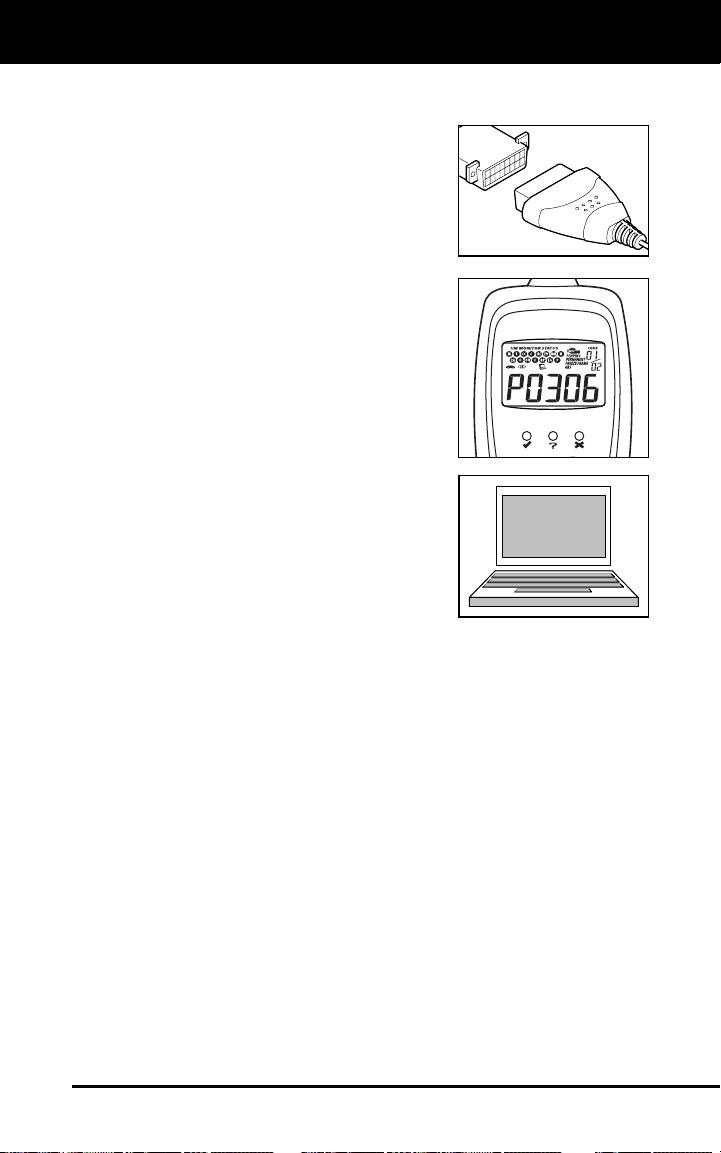
Easy To Use . . . .
Connect the Code Reader to the
vehicle’s test connector.
Turn the ignition key "On.” DO NOT start
the engine.
The Code Reader will automatically link
to the vehicle’s computer.
Easy To View . . . .
The Code Reader retrieves stored codes
and displays I/M Monitor Status.
Codes are displayed on the Code
Reader’s LCD display screen; System
Status is displayed by LED indicators.
Easy To Define . . . .
Visit www.innova.com for Fault Code
Definitions.

Safety Precautions
SAFETY FIRST
Craftsman 14063 3
SAFETY FIRST!
This manual describes common test procedures used by experienced
service technicians. Many test procedures require precautions to avoid
accidents that can result in personal injury, and/or damage to your
vehicle or test equipment. Always read your vehicle's service manual
and follow its safety precautions before and during any test or service
procedure. ALWAYS observe the following general safety precautions:
When an engine is running, it produces carbon monoxide, a
toxic and poisonous gas. To prevent serious injury or death
from carbon monoxide poisoning, operate the vehicle ONLY
in a well-ventilated area.
To protect your eyes from propelled objects as well as hot
or caustic liquids, always wear approved safety eye
protection.
When an engine is running, many parts (such as the coolant
fan, pulleys, fan belt etc.) turn at high speed. To avoid serious
injury, always be aware of moving parts. Keep a safe distance
from these parts as well as other potentially moving objects.
Engine parts become very hot when the engine is running.
To prevent severe burns, avoid contact with hot engine
parts.
Before starting an engine for testing or trouble-shooting, make
sure the parking brake is engaged. Put the transmission in
park (for automatic transmission) or neutral (for manual
transmission). Block the drive wheels with suitable blocks.
Connecting or disconnecting test equipment when the
ignition is ON can damage test equipment and the vehicle's
electronic components. Turn the ignition OFF before
connecting the Code Reader to or disconnecting the Code
Reader from the vehicle’s Data Link Connector (DLC).
To prevent damage to the on-board computer when taking
vehicle electrical measurements, always use a digital
multimeter with at least 10 MegOhms of impedance.
The vehicle's battery produces highly flammable hydrogen
gas. To prevent an explosion, keep all sparks, heated items
and open flames away from the battery.
Don't wear loose clothing or jewelry when working on an
engine. Loose clothing can become caught in the fan,
pulleys, belts, etc. Jewelry is highly conductive, and can
cause a severe burn if it makes contact between a power
source and ground.
N
L
D
R
P
About the Code Reader
VEHICLES COVERED
4 Craftsman 14063
VEHICLE EMISSION CONTROL INFORMATION
VEHICLE
MANUFACTURER
OBD II
CERTIFIED
ENGINE FAMILY EFN2.6YBT2BA
DISPLACEMENT 2.6L
THIS VEHICLE CONFORMS TO U.S. EPA AND STATE
OF CALIFORNIA REGULATIONS APPLICABLE TO
1999 MODEL YEAR NEW TLEV PASSENGER CARS.
REFER TO SERVICE MANUAL FOR ADDITIONAL INFORMATION
TUNE-UP CONDITIONS: NORMAL OPERATING ENGINE TEMPERATURE,
ACCESSORIES OFF, COOLING FAN OFF, TRANSMISSION IN NEUTRAL
SPARK PLUG
TYPE NGK BPRE-11
GAP: 1.1MM
CATALYST
EXHAUST EMISSIONS STANDARDS STANDARD CATEGORY
CERTIFICATION
IN-USE
TLEV
TLEV INTERMEDIATE
OBD II
CERTIFIED
VEHICLES COVERED
The Code Reader is designed to work on all OBD 2 compliant vehicles.
All 1996 and newer vehicles (cars and light trucks) sold in the United
States are OBD 2 compliant. This includes all Domestic, Asian and
European vehicles.
Some 1994 and 1995 vehicles are OBD 2 compliant. To find out if a
1994 or 1995 vehicle is OBD 2 compliant, check the following:
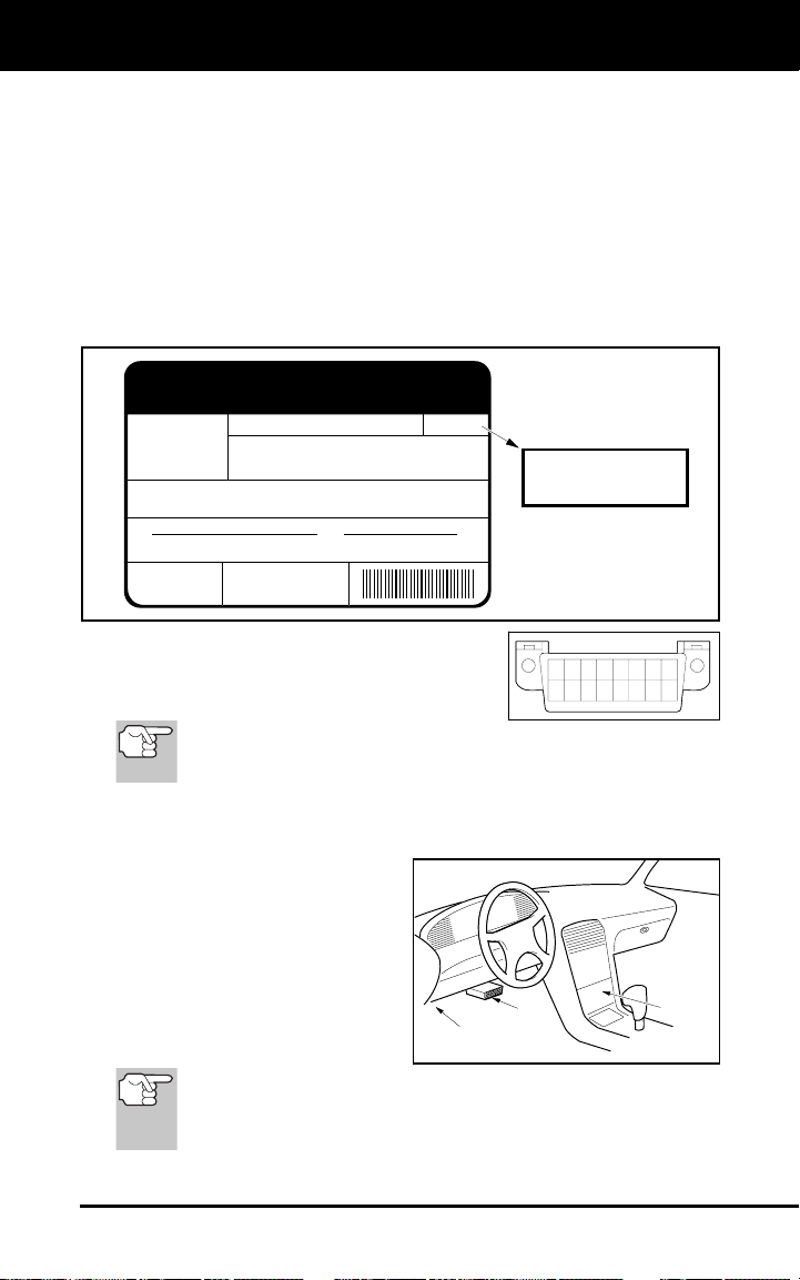
1. The Vehicle Emissions Control Information (VECI) Label. This label
is located under the hood or by the radiator of most vehicles. If the
vehicle is OBD 2 compliant, the label will state “OBD II Certified.”
2. Government Regulations require that all
OBD2 compliant vehicles must have a
“common” sixteen-pin Data Link
Connector (DLC).
Some 1994 and 1995 vehicles have 16-pin connectors but are not
OBD2 compliant. Only those vehicles with a Vehicle Emissions
Control Label stating “OBD II Certified” are OBD2 compliant.
Data Link Connector (DLC) Location
The 16-pin DLC is usually
located under the instrument
panel (dash), within 12 inches
(300 mm) of center of the panel,
on the driver’s side of most
vehicles. It should be easily
accessible and visible from a
kneeling position outside the
vehicle with the door open.
On some Asian and European vehicles the DLC is located
behind the “ashtray” (the ashtray must be removed to access it)
or on the far left corner of the dash. If the DLC cannot be
located, consult the vehicle’s service manual for the location.
12345678
9 10111213141516
NEAR
CENTER
OF DASH
BEHIND
ASHTRAY
LEFT CORNER
OF DASH
About the Code Reader
CONTROLS AND INDICATORS
Craftsman 14063 5
CONTROLS AND INDICATORS
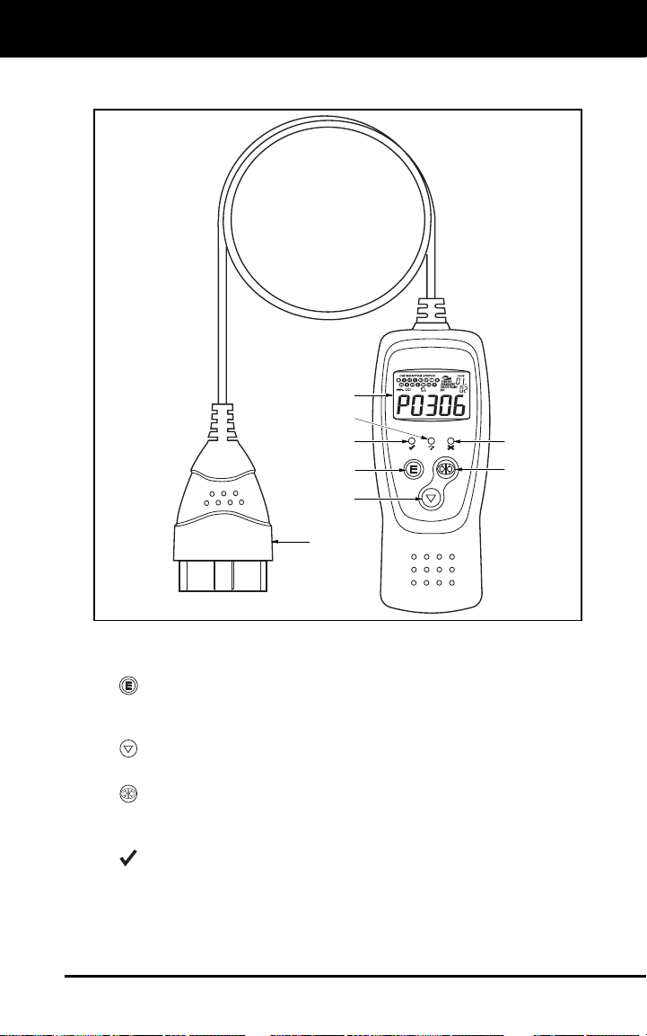
Figure 1. Controls and Indicators
See Figure 1 for the locations of items 1 through 9, below.
1.
E
ERASE button - Erases Diagnostic Trouble Codes (DTCs) and
"Freeze Frame" data from your vehicle's computer, and resets
Monitor status.
2.
SCROLL button - Scrolls the LCD display to view DTCs when
more than one DTC is present.
3.
LINK button - Links the Code Reader with the vehicle's PCM to
retrieve DTCs from the computer's memory, and to view I/M
Readiness Monitor status.
4.
GREEN LED - Indicates that all engine systems are running
normally (all Monitors on the vehicle are active and performing their
diagnostic testing, and no DTCs are present).
7
4
1
5
2
3
6
8
About the Code Reader
DISPLAY FUNCTIONS
6 Craftsman 14063
5.
YELLOW LED - Indicates there is a possible problem. A
“Pending” DTC is present and/or some of the vehicle's emission
monitors have not run their diagnostic testing.
6.
RED LED - Indicates there is a problem in one or more of the
vehicle's systems. The red LED is also used to show that DTC(s)
are present. DTCs are shown on the Code Reader’s LCD display. In
this case, the Multifunction Indicator (“Check Engine”) lamp on the
vehicle's instrument panel will light steady on.
7. LCD Display - Displays test results, Code Reader functions and
Monitor status information. See DISPLAY FUNCTIONS, below, for
details.
8. CABLE - Connects the Code Reader to the vehicle's Data Link
Connector (DLC).
DISPLAY FUNCTIONS
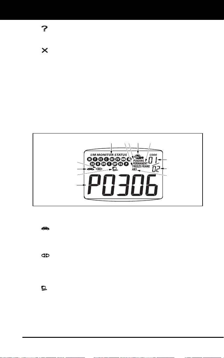
Figure 2. Display Functions
See Figure 2 for the locations of items 1 through 13, below.
1.
Vehicle icon - Indicates whether or not the Code Reader is
being properly powered through the vehicle's Data Link Connector
(DLC). A visible icon indicates that the Code Reader is being
powered through the vehicle's DLC connector.
2.
Link icon - Indicates whether or not the Code Reader is
communicating (linked) with the vehicle's on-board computer. When
visible, the Code Reader is communicating with the computer. If the
Link icon is not visible, the Code Reader is not communicating with
the computer.
3.
Computer icon - When this icon is visible it indicates that the
Code Reader is linked to a personal computer. An optional “PC Link
Kit” is available that makes it possible to upload retrieved data to a
personal computer.
4. DTC Display Area - Displays the Diagnostic Trouble Code (DTC)
number. Each fault is assigned a code number that is specific to that
fault.
1
3
2
4
10
11
9
12
5
7
68

About the Code Reader
DISPLAY FUNCTIONS
Craftsman 14063 7
,
5. MIL icon - Indicates the status of the Malfunction Indicator Lamp
(MIL). The MIL icon is visible only when a DTC has commanded the
MIL on the vehicle's dashboard to light.
6. Pending icon - Indicates the currently displayed DTC is a "Pending"
code.
7. PERMANENT icon - Indicates the currently displayed DTC is a
“Permanent” code.
8. FREEZE FRAME icon - Indicates that “Freeze Frame” data has been
stored in the vehicle’s computer for the currently displayed DTC.
9. ABS icon - Indicates that the currently displayed DTC is an “ABS”
code.
10. Code Number Sequence - The Code Reader assigns a sequence
number to each DTC that is present in the computer's memory,
starting with "01.” This helps keep track of the number of DTCs
present in the computer's memory. Code number "01" is always the
highest priority code, and the one for which "Freeze Frame" data
has been stored.
11. Code Enumerator - Indicates the total number of codes retrieved
from the vehicle’s computer.
12. Monitor icons - Indicates which Monitors are supported by the
vehicle under test, and whether or not the associated Monitor has
run its diagnostic testing (Monitor status). When a Monitor icon is
solid, it indicates that the associated Monitor has completed its
diagnostic testing. When a Monitor icon is flashing, it indicates that
the vehicle supports the associated Monitor, but the Monitor has not
yet run its diagnostic testing.
The I/M Monitor Status icons are associated with INSPECTION
and MAINTENANCE (I/M) READINESS STATUS. Some states
require that all vehicle Monitors have run and completed their
diagnostic testing before a vehicle can be tested for Emissions
(Smog Check). A maximum of eleven Monitors are used on OBD
2 systems. Not all vehicles support all eleven Monitors. When the
Code Reader is linked to a vehicle, only the icons for Monitors
that are supported by the vehicle under test are visible on the
display.

Onboard Diagnostics
COMPUTER ENGINE CONTROLS
8 Craftsman 14063
COMPUTER ENGINE CONTROLS
The Introduction of Electronic Engine Controls
As a result of increased air pollution (smog) in large cities,
such as Los Angeles, the California Air Resources Board
(CARB) and the Environmental Protection Agency (EPA)
set new regulations and air pollution standards to deal with
the problem. To further complicate matters, the energy crisis of
the early 1970s caused a sharp increase in fuel prices over a
short period. As a result, vehicle manufacturers were not only
required to comply with the new emissions standards, they also
had to make their vehicles more fuel-efficient. Most vehicles
were required to meet a miles-per-gallon (MPG) standard set by the U.S.
Federal Government.
Precise fuel delivery and spark timing are needed to reduce vehicle
emissions. Mechanical engine controls in use at the time (such as
ignition points, mechanical spark advance and the carburetor)
responded too slowly to driving conditions to properly control fuel
delivery and spark timing. This made it difficult for vehicle manufacturers
to meet the new standards.
A new Engine Control System had to be designed and integrated with
the engine controls to meet the stricter standards. The new system had
to:
Respond instantly to supply the proper mixture of air and fuel for any
driving condition (idle, cruising, low-speed driving, high-speed
driving, etc.).
Calculate instantly the best time to “ignite” the air/fuel mixture for
maximum engine efficiency.
Perform both these tasks without affecting vehicle performance or
fuel economy.
Vehicle Computer Control Systems can perform millions of calculations
each second. This makes them an ideal substitute for the slower
mechanical engine controls. By switching from mechanical to electronic
engine controls, vehicle manufacturers are able to control fuel delivery
and spark timing more precisely. Some newer Computer Control
Systems also provide control over other vehicle functions, such as
transmission, brakes, charging, body, and suspension systems.
Electronic Computer C
o
ntrol Systems make it possible
for vehicle manufacturers to comply with the tougher
emissions and fuel efficiency standards mandated by
State and Federal Governments.

Onboard Diagnostics
COMPUTER ENGINE CONTROLS
Craftsman 14063 9
,
The Basic Engine Computer Control System
The on-board computer is the heart of the Computer
Control System. The computer contains several programs
with preset reference values for air/fuel ratio, spark or
ignition timing, injector pulse width, engine speed, etc.
Separate values are provided for various driving conditions,
such as idle, low speed driving, high-speed driving, low load,
or high load. The preset reference values represent the ideal
air/fuel mixture, spark timing, transmission gear selection,
etc., for any driving condition. These values are programmed
by the vehicle manufacturer, and are specific to each vehicle model.
Most on-board computers are located inside the vehicle behind the dashboard,
under the passenger’s or driver’s seat, or behind the right kick panel. However,
some manufacturers may still position it in the engine compartment.
Vehicle sensors, switches, and actuators are located throughout the
engine, and are connected by electrical wiring to the on-board computer.
These devices include oxygen sensors, coolant temperature sensors,
throttle position sensors, fuel injectors, etc. Sensors and switches are
input devices. They provide signals representing current engine
operating conditions to the computer. Actuators are output devices. They
perform actions in response to commands received from the computer.
The on-board computer receives information inputs from sensors and
switches located throughout the engine. These devices monitor critical
engine conditions such as coolant temperature, engine speed, engine
load, throttle position, air/fuel ratio etc.
The computer compares the values received from these sensors with its
preset reference values, and makes corrective actions as needed so
that the sensor values always match the preset reference values for the
current driving condition. The computer makes adjustments by
commanding other devices such as the fuel injectors, idle air control,
EGR valve or Ignition Module to perform these actions.
The Computer Control System consists of an on-board
computer and several related control devices (sensors,
switches, and actuators).
OUTPUT DEVICES
Fuel Injectors
Idle Air Control
EGR Valve
Ignition Module
On-Board
Computer
INPUT DEVICES
Coolant Temperature Sensor
Throttle Position Sensor
Fuel Injectors
INPUT DEVICES
Oxygen Sensors
TYPICAL COMPUTER
CONTROL SYSTEM
 Loading...