


OPERATOR’S MANUAL
Drawer accessory
10133 Red/Black
10139 Black/Platinum
For use with CRAFTSMAN workbench 10132 or 10138
CAUTION: Read and follow all Safety Rules and Operating Instructions before first use of this product.
Retain this document for future reference.
Distributed by Sears Brands Management Corporation., Hoffman Estates, IL 60179
F1655A1
SAFETY
SAFETY WARNINGS AND CAUTIONS:
•Use appropriate safety equipm ent when using power and hand tools. Failure to do so m ay cause personal injury or product damage.
•Use adequate manpower when assembling and moving this unit. Failure to do so m ay cause personal injury or product damage.
•DO NOT stand on this product. You may fall which may cause personal injury.
•DO NOT mount this product on a truck bed or any other moving object. This may cause personal injury or product damage.
•Appropriately secure this product before moving it with a forklift.
•DO NOT alter this product in any manner. For exam ple, do not weld external lockbars or attach electrical equipm ent. This m ay cause product dam age or personal injury.
•Keep the product on level surfaces. The product may becom e unstable and tip if stored or moved on an un-level surface, which may cause personal injury or product damage.
•BE CAREFUL when opening more than one drawer. The product may becom e unstable and tip, which may cause personal injury or product damage.
•DO NOT step in the drawers. You may fall which may cause personal injury.
•Maxim um weight for each drawer should be no m ore than (35) pounds.
Tools Required: |
|
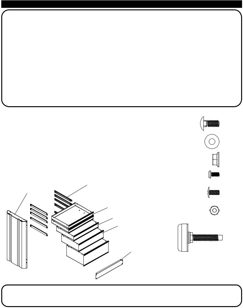
Parts Included: |
|
Hardware Included: |
|
|
Socket wrench |
Label |
Description |
Quantity |
1/4-20 X 5/8 |
AA(12) |
|
7/16" socket |
A |
Side |
1 |
carriage bolt |
||
11/32" wrench |
B |
Rail |
1 |
|
|
|
Screwdriver, crosstip |
C |
Drawer (3") |
2 |
|
|
|
Screwdriver, flathead |
D |
Drawer (4") |
1 |
5/16 |
BB(12) |
|
Square |
E |
Drawer (6") |
1 |
|||
washer |
||||||
|
F |
Drawer (9") |
1 |
|
||
|
|
|
||||
|
G |
Slide |
10 |
|
|
|
|
|
|
|
1/4-20 |
CC(12) |
|
|
|
|
|
flange nut |
|
|
|
|
|
|
8-32 X 3/8 |
DD(20) |
|
|
|
|
|
self tapping screw |
|
G (10)
A
C (2)
D
E
 F
F
B
8-32 X 3/8 |
EE(20) |
truss head screw |
|
8-32 |
FF(20) |
keps nut |
Leveling |
EE(4) |
foot |
|
Call 1-800-4MY-HOME (1-800-469-4663) for Service Parts.
Refer to Service Parts Drawing for full listing of Service Parts.
2

ASSEMBLY
STEP (2):
AA(10)
STEP (1):
BB(10)
GG(2)
CC(10)
•Ensure that the leveling screws on the work bench are extended to at least (1.5) inch, (38 mm). See operation section; Leveling foot adjustment.
1.5"
(38 mm)
•Assemble (2) adjustment feet (GG) in side panel (A). Make sure both leveling feet (GG) are fully retracted into A.
A


 GG
GG
Note: Drawer kit may be installed on left or right side of workbench. Installation is shown on right side.
•Lean side panel (A) at an angle to fit under the rails on the workbench.
•Line up the side panel with notches on the top rails of the workbench. Rotate side panel (A) to the upright position inside notches.
•Attach side panel (A) using (6) bolts (AA), (6) washers (BB), and (6) nuts (CC).
•Attach rail (B), as shown, using (4) bolts (AA), (4) washers (BB), and (4) nuts CC.
•Adjust bench to desired height. (See operation section; Leveling foot adjustment.)
Workbench Top
removed for clarity
(A) fits in notch in
workbench rail
A
B
3
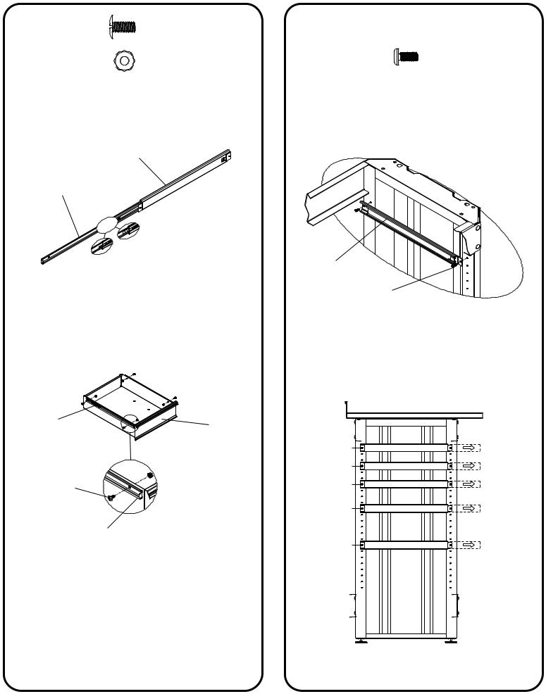
STEP (3): |
EE(20) |
|
FF(20) |
• Separate slide parts. (See drawer removal instructions.)
Gu
Gd
•Attach (2) drawer slides (Gd) to each drawer (C, D, E, and F) as shown.
•Wrench tighten.
Release
Drawer
 FF
FF
EE
Gd
STEP (4):
DD(20)
•Install (10) frame slides (Gu) on workbench frame, as shown, using (2) (DD) in each (Gu).
Workbench top removed for clarity.
Gu
DD
NOTE: Drawers may be organized in several configurations, below is the slide positioning for the recommended drawer configuration.
24 |
|
21 |
F |
|
|
18 |
R |
|
|
14 |
O |
|
|
|
N |
8 |
T |
|
4
 Loading...