

Page 1
FT/SB/01
I Citofonia e videocitofonia con cablaggio
a 2 fili non polarizzati.
GB Door and video entry phone systems
with unpolarised 2-wire cabling.
F Parlophonie et visiophonie
avec câblage à 2 fils non polarisés.
D Gegensprech- und
Video-Gegensprechanlagen,
verdrahtet mit 2 ungepolten Drähten
I • Evitare di porre i fili di montante in prossimità di cavi di alimentazione (220/380V).
• Connettere il telaio portamoduli a terra (vedi fig. 1).
• Effettuare l’installazione seguendo scrupolosamente le istruzioni fornite
dal costruttore ed in conformità alle normative vigenti.
• Tutti gli apparecchi devono essere destinati esclusivamente all’uso
per cui sono stati concepiti.
GB •Avoid placing the riser wires near power supply cables (220/380V).
• Connect the module-holder frame to earth (see fig. 1).
• Carry out installation following the manufacturer's instructions very carefully,
and in compliance with the laws in force.
• All the pieces of apparatus must only be used of the purposes
they have been built for.
F • Eviter de placer les fils de montant à proximité des câbles d’alimentation (220/380V).
• Connecter le cadre porte-modules à la terre (voir fig. 1).
• Effectuer l’installation en suivant scrupuleusement les instructions fournies par
le constructeur et en vous conformant aux réglementations en vigueur.
• Tous les appareils doivent être strictement destinés à l’emploi pour lequel ils
ont été conçus.
D • Die Drähte der Steigleitungen nicht in der Nähe der Stromkabel
(220/380V) verlegen.
• Den Rahmen der Modulhalterung mit der Erdleitung
verbinden (siehe Abb.1).
• Die Installationen sind nach den Anweisungen des
Herstellers und gemäß den geltenden Vorschriften
gewissenhaft auszuführen.
• Alle Geräte dürfen ausschließlich nur zu
dem Zweck eingesetzt werden,
für den sie entwickelt worden sind.
GROUP S.P.A.
Avvertenze
Warnings
Instructions
Allgemeine Hinweise
Fig. 1
1
Regole generali di installazione
General installation instructions
Règles générales d’installation
Allgemeine Installationsregeln
I • Connettere al massimo 100 derivati
per ogni montante.
• Connettere al massimo 3 derivati
con il medesimo codice utente.
• Il sistema può gestire al massimo
240 utenti.
• In impianti solo citofonici la
distanza massima di
funzionamento tra porta e
citofono più lontano è di 400mt
indipendentemente dal tipo di
cavo utilizzato e dalla tipologia
d’impianto.
GB •
Connect a maximum of 100 units
for each riser.
• Connect a maximum of 3 units with
each user code.
• The system can manage a
maximum of 240 users.
• In door entry phone only
systems, the maximum operating
distance between the door and
the telephone furthest away is
400mt regardless of the type of
cable used and the type of
system.
F •
Brancher au maximum 100 dérivés
pour chaque montant.
• Brancher au maximum 3 dérivés
avec le même code usager.
• Le système peut gérer 240 usagers
au maximum.
•
Dans des installations exclusivement
parlophoniques la distance
maximum de fonctionnement entre la
porte et le parlophone le plus éloigné
est de 400 m indépendamment du
type de câble utilisé et de la
typologie de l’installation.
D • Maximal 100 Abzweigungen je
Steigleitung anschließen.
• Maximal 3 Abzweigungen mit
demselben Benutzercode
anschließen.
• Das System ist auf maximal 240
Benutzer ausgelegt.
• Bei reinen Gegensprechanlagen
darf der Abstand zwischen Tür
und Haustelefon maximal 400 m
betragen, unabhängig von der Art
des benutzten Kabels und der
Anlage.
Sezione conduttori di alimentazione (mm2) per il monitor e posto esterno
Cross-section of power supply conductors (mm2) for the monitor and the entrance unit
Section conducteurs d’alimentation (mm2) pour le moniteur et le poste extérieur
Querschnitt der Stromversorgungsleitungen (mm2) für den Monitor und die Aussenstation
Alimentazione porta
Door power supply
Alimentation porte
Stromversorgung Tür
** Oltre i 50 metri alimentare con trasformatore a parte l’elettroserratura e le lampade illuminazione nomi.
** For distances higher than 50 metres, use an additional transformer to power the electric lock and the name lighting lamps.
** Pour distances supérieures aux 50 mètres, utiliser un transformateur pour alimenter la gâche et les lampes éclairage des noms.
** Wenn die Entfernung mehr als 50Mt. ist, muss man einen Transformator benutzen, um das Schloss und die Namenlampen zu speisen.
* Oltre le 3 lampade di illuminazione nomi utilizzare un trasformatore separato art. 1200 ogni 3 lampade
* When there are more than 3 name lighting lamps, use an additional transformer art. 1200 every 3 lamps
* Quand on a plus de 3 lampes éclairage des noms, utiliser un transformateur additionnel art. 1200 toutes les 3 lampes
* Wenn es mehr als 3 Namenlampen gibt, einen Transformator Art. 1200 jeden 3 lampen zu benutzen
Alimentazione monitor con art 1536
Monitor power supply with art. 1536
Alimentation moniteur avec art. 1536
Stromversorgung Monitor mit Art. 1536
Alimentazione monitor con art. 1212
Monitor power supply with art. 1212
Alimentation monitor avec art. 1212
Stromversorgung Monitor mit Art. 1212
0.22
0.22 1.00
1.00 1.50
0/12V~
0/+20
0/18V~
0/21V~
1.00
0.80
2.50
0.80
**
*
1.00 1.50 2.50
1 m 20 m 50 m 100 m 200 m 300 m
SELEZIONARE IL
CON
Page 2

2
Regole d’installazione per impianti videocitofonici
Installation instructions for video door entry systems
Règles de montage pour les installations visiophoniques
Installationsregeln für Video-Gegensprechanlagen
GB In the branches towards each user,
insert terminal
1214 supplied with
bracket 4614W/A or 1561 on the riser.
Terminate each riser or branch with
art.
1216 provided with video
modules 4060 or 4061 or with line
amplifier 4833.
According to the cable used for the
riser, assess the maximum distance
which can be reached between the
video external unit and the furthest
branch
1214 (A1 in figure 2).
According to the cable used for the
branch, assess the maximum
distance which can be reached from
the monitor to the branch terminal
1214 (B in figure 2).
According to the cable used for the
riser, set closure of
art.
1216 as
indicated in figure 2, 3 and 6.
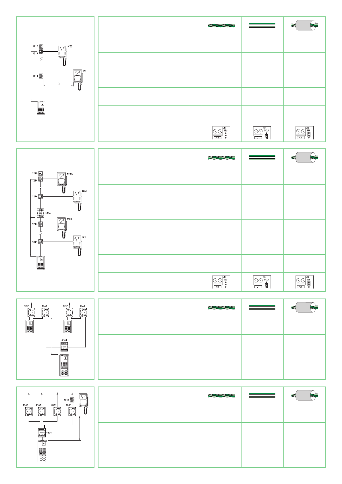
With more than
50 users it is always
necessary to insert a line amplifier
art. 4833 (figure 3) on the riser.
Regardless of the number of users,
for riser lengths over limit A1
(figure 3) insert a line amplifier
art.
4833 (figure 3).
Up to
3 line amplifiers
art.
4833 can
be inserted on the riser to a
maximum total distance of 3xA1 and
in any case not more than
400mt.
In the case of systems with main and
secondary entrances
(figure 4) in
any case when the riser divides into
several branches
(figure 5), it is
necessary to use the line
concentrator art. 4834.
Art.
4834 allows a maximum of 10
branches.
When using the line concentrator, it
is necessary to insert an amplifier
art. 4833 for each output of
art.
4834 (figure 4 and 5).
In the case of systems with
secondary entrances, it is advisable
to position amplifier
art.
4833 near
the switching device
art.
1224
(figure 4).
According to the cable used for
connection, assess the maximum
distance which can be reached
between the video external unit and
the amplifier
art.
4833 passing
through line concentrator
art.
4834
(C in fig. 4 and 5).
Collegamento in cascata in impianti videocitofonici
Cascade connection in video door entry systems
Connexion en cascade dans des installations visiophoniques
Kaskatenschaltung bei Video-Gegensprechanlagen
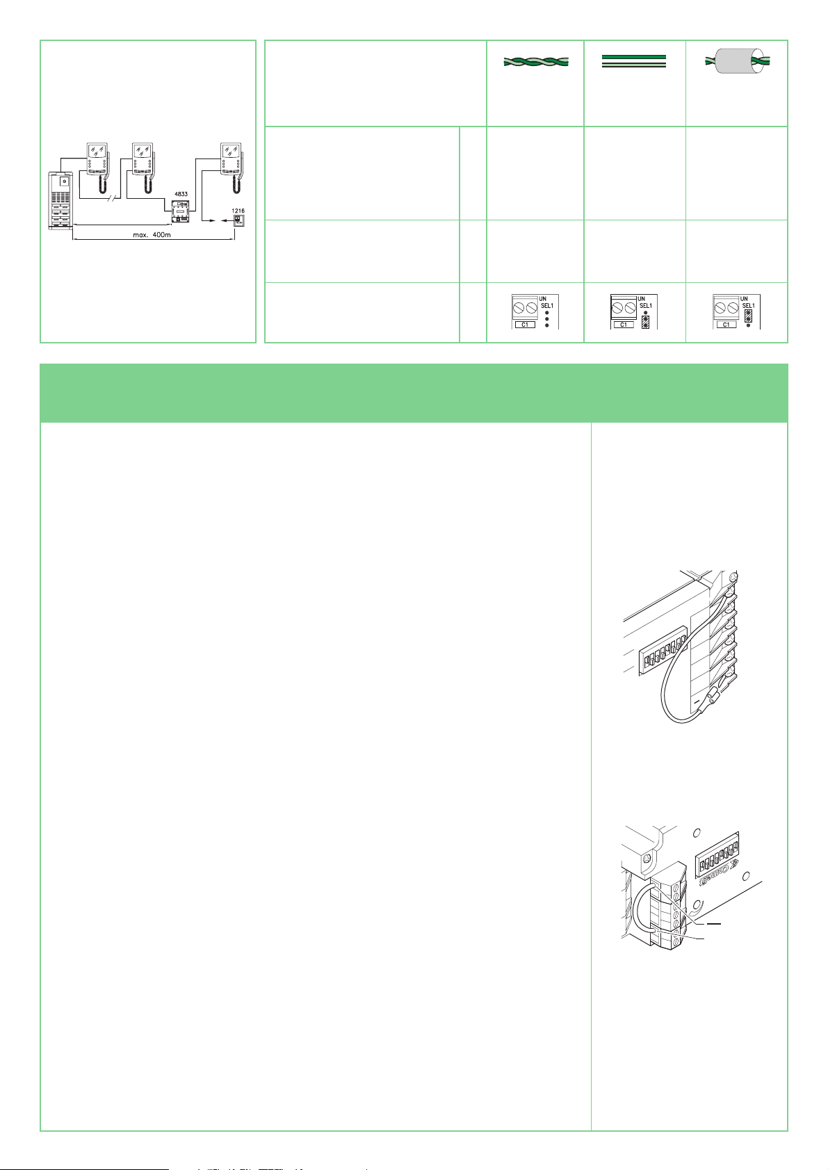
I
In alternativa all’uso dei morsetti di
derivazione art. 1214 e del
concentratore di linea è possibile
collegare gli utenti in cascata (figura 6).
In funzione dei cavi utilizzati per il
montante valutare la distanza
massima raggiungibile dal posto
esterno video al monitor più lontano
(D in figura 6).
Terminare il montante con
l’art.
1216 (figura 6).
Indipendentemente dal numero di
utenti, per lunghezze di montante
superiori al limite
D (figura 6)
inserire un amplificatore di linea
art. 4833 per una distanza massima
comunque non superiore ai
400mt.
GB As an alternative to the use of
branch terminals
art.
1214 and line
concentrator, it is possible to connect
the users in cascade (figure 6).
According to the cables used for the
riser, assess the maximum distance
which can be reached from the video
external unit to the furthest monitor
(D in figure 6).
Terminate the riser with
art.
1216
(figure 6). Regardless of the number
of users, for riser lengths over limit D
(figure 6), insert a line amplifier
art.
4833 to a maximum distance in any
case of not over 400mt.
F Dans l’alternative à l’emploi des bornes
de dérivation art. 1214 et du
concentrateur de ligne, les usagers
peuvent être connectés en cascade
(figure 6). En fonction des câbles
utilisés pour le montant, évaluer la
distance maximum pouvant être
atteinte du poste extérieur vidéo au
moniteur le plus éloigné (D figure 6).
Terminer le montant avec l’art. 1216
(
figure 6
). Indépendamment du
nombre d’usagers pour des longueurs
de montant supérieures à la limite
D
(figure 6)
insérer un amplificateur de
ligne art. 4833 pour une distance
maximum de toute façon jamais
supérieure à 400m.
D An Stelle der Abzweigklemmen
Art.
1214 und des Leitungskonzentrators
können die Benutzer in
Kaskatenschaltung miteinander
verbunden werden
(Abb. 6). Je nach
dem für die Steigleitung verwendeten
Kabel ist der maximale Abstand
zwischen Tür mit Video-Modul und
dem entferntesten Monitor (D in Abb.
6) zu beachten. Die Steigleitung mit
Art.
1216 (Abb. 6). abschließen. Bei
Steigleitungen, die länger sind als
maximal
D (Abb. 6), ist unabhängig
von der Benutzerzahl ein
Leitungsverstärker
Art.
4833
einzusetzen. Die Gesamtlänge darf in
jedem Fall 400 m nicht übersteigen.
D Die mit dem Bügel 4614W/A oder dem
Art. 1561 gelieferte Klemme 1214 auf
der Steigleitung an den Abzweigungen
zu jedem Benutzer einsetzen.
Jede Steig- oder Abzweigleitung mit
Art. 1216 abschließen, der mit
Video-Modulen 4060 oder 4061
oder mit dem Leitungsverstärker 4833
geliefert wird.
Je nach dem für die Steigleitung
verwendeten Kabel ist der maximale
Abstand zw.Tür mit Video-Modul und
der entferntesten Abzweigung (A1 in
Abb. 2) zu beachten.
Je nach dem für die Abzweigleitung
verwendeten Kabel ist der maximale
Abstand zwischen der monitor und die
1214 (B in Abb. 2) zu beachten.
Je nach dem für die Steigleitung
verwendeten Kabel gemäß den
Abschluss des Art. 1216
(in Abb. 2, 3 und 6)
anbringen.
Bei mehr als 50 Benutzern muss
immer ein Leitungsverstärker
Art. 4833 eingesetzt werden
(Abbildung 3).
Bei Steigleitungen, die länger sind als
maximal A1
(Abb. 3), ist unabhängig
von der Benutzerzahl ein LeitungsVerstärker
Art.
4833 einzusetzen
(Abb. 3). Auf der Steigleitung können
auf einer 400 m nicht übersteigenden
Länge von 3xA1 bis zu max. 3
Leitungsverstärker
Art.
4833
eingesetzt werden.
Bei Anlagen mit Haupt- und NebenEingängen oder jedenfalls (Abb. 4),
wenn sich die Steigleitung in mehrere
Abzweigungen aufteilt (Abb. 5), muss
der Leitungskonzentrator Art. 4834
eingesetzt werden, der maximal 10
Abzweigungen zulässt.
Wenn man einen Leitungskonzentrator
verwendet, muss man an jeden
Ausgang des
Art.
4834 einen
Verstärker Art. 4833 setzen (Abb. 4
und 5)
. Bei Anlagen mit Neben-
Eingängen ist es ratsam, den
Art.
4833 in Übereinstimmung mit dem
Umschalter
Art.
1224 (Abb. 4)
anzubringen. Je nach Art des Kabels,
das für die Verbindung über den
Leitungs-Konzentrator
Art.
4834
verwendet wird, ist der max. Abstand
zwischen Tür mit Video-Modul und
Verstärker
Art.
4833 zu beachten
(C in Abb. 4 und 5).
F Dans les embranchements vers chaque
usager insérer sur le montant la borne
1214 fournie avec la bride 4614W/A ou
l’art. 1561.
Terminer chaque montant ou chaque
embranchement par l’art. 1216 qui
équipe les modules vidéo 4060 ou 4061
ou l’amplificateur de ligne 4833.
En fonction du câble utilisé pour le
montant évaluer la distance maximum
pouvant être atteinte entre le poste
extérieur video et l’embranchement le
plus éloigné 1214 (A1 figure 2).
En fonction du câble utilisé pour
l’embranchement évaluer la distance
maximum pouvant être atteinte entre
l’embranchement de montant
1214
et le moniteur (B figure 2).
En fonction du câble utilisé pour le
montant programmer la fermeture de
l’art. 1216 de la manière indiquée au in
figure 2, 3 et 6. Au-delà des 50 usagers
il est toujours nécessaire d’insérer sur le
montant un amplificateur de ligne
art. 4833 (fig. 3).
Indépendamment du nombre d’usagers,
pour des longueurs de montant
supérieures à la limite A1
(figure 3)
insérer un amplificateur de ligne
art. 4833 (figure 3).
Sur le montant, possibilité d’insérer
jusqu’à 3 amplificateurs de ligne
art. 4833 pour une distance totale
maximum de 3xA1 et de toute façon
jamais supérieure à
400m.
Dans le cas d’installations avec des
entrées principales et secondaires
(figure 4) ou lorsque le montant se
divise en plusieurs embranchements
(figure 5), employer le concentrateur de
ligne
art. 4834.L’art. 4834 consent un
maximum de 10 embranchements.
Lors de l’utilisation du concentrateur de
ligne, il est nécessaire d’insérer un
amplificateur
art. 4833 pour chaque
sortie de l’art. 4834 (figure 4).
Dans le cas d’installations avec des
entrées secondaires, il est conseillé de
mettre en place l’amplificateur
art. 4833
en correspondance du commutateur
art. 1224 (figure 4). En fonction du
câble utilisé pour la connexion, évaluer
la distance maximum pouvant être
atteinte entre l’entrée vidéo et
l’amplificateur
art. 4833 en passant par
le concentrateur de ligne art. 4834
(C in figure 4 et 5).
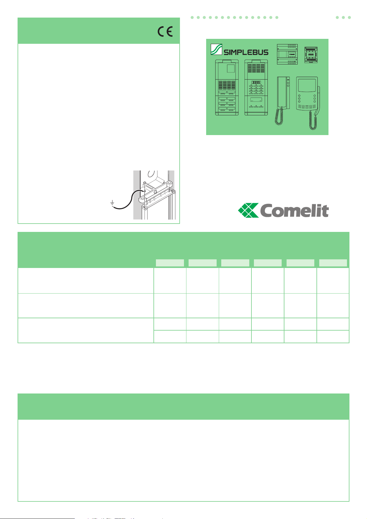
I Nelle diramazioni verso ogni utente
inserire sul montante il morsetto
1214
fornito a corredo della staffa 4614W/A
o del 1561.
Terminare ogni montante o
diramazione con l’art. 1216 fornito a
corredo dei moduli video 4060 o 4061
o dell’amplificatore di linea 4833.
In funzione del cavo utilizzato
per il montante valutare la distanza
massima raggiungibile tra posto
esterno video
e la diramazione
1214 più lontana
(A1 in figura 2).
In funzione del cavo usato per la
diramazione valutare la distanza
massima del monitor dal
1214
(B in figura 2).
In funzione del cavo usato per
il montante impostare la chiusura
dell’
art.
1216 come indicato
nelle figure 2, 3 e 6.
Oltre i 50 utenti è sempre necessario
inserire sul montante un amplificatore
di linea
art. 4833 (figura 3).
Indipendentemente dal numero di
utenti, per lunghezze di montante
superiori al limite A1 (
figura 3
)
inserire un amplificatore di linea
art.
4833 (figura 3)
.
Sul montante, è possibile inserire fino
a
3 amplificatori di linea art. 4833 per
una distanza massima totale di 3xA1
e comunque non superiore ai 400mt.
Nel caso di impianti con porte principali
e secondarie
(figura 4) o comunque
quando il montante si divide in più
diramazioni (figura 5) è necessario
impiegare il concentratore
di linea art. 4834.
L’art. 4834 consente
al massimo 10 diramazioni.
Utilizzando il concentratore
di linea è necessario inserire
un amplificatore
art. 4833 per ogni
uscita del 4834 (fig. 4 e 5).
Nel caso di impianti con porte
secondarie è consigliabile posizionare
l’amplificatore
art. 4833 in
corrispondenza dello scambio
art. 1224 (figura 4).
In funzione del cavo usato per il
collegamento valutare la distanza
massima raggiungibile tra il posto
esterno video e l’amplificatore
4833
passando per il concentratore di
linea art. 4834 (C in figura 4 e 5).
Page 3
3
Doppino telefonico twistato
Twisted telephone cable
Boucle téléphonique twistée
Verdrillte Telefon-Doppellitze
Cavo non intrecciato
Unbraided cable
Câble non retors
Nicht geflochtenes Kabel
Cavo intrecciato e schermato
Braided and shielded cable
Câble retors et blindé
Geflochtenes u. abgeschirmtes Kabel
150 m 100 m 80 m
40 m 20 m 15 m
50 50 50
A1
B
1216
Distanza massima tra posto esterno video
e diramazione art. 1214 più lontana.
Maximum distance between the video entrance unit
and the furthest branch terminal
art. 1214.
Distance maximum entre le poste extérieur vidéo
et la borne art. 1214 la plus éloignée.
Maximaler Abstand zwischen Tür mitVideo-Modul
und der entferntesten Art. 1214.
Distanza massima del monitor dal
art. 1214.
Maximum distance between monitor and branch terminal art. 1214.
Distance maximum du moniteur de la borne art. 1214.
Maximaler Abstand des Monitors von der
art. 1214.
N° massimo di utenti
Maximum user n°
Nombre maximum d’usagers
Maximale Benutzer N°
Posizione selettore su terminazione di linea
art. 1216.
Position of selector on termination of line art. 1216.
Position du sélecteur sur la borne de ligne art. 1216.
Position des Wâhlschalters auf dem Leitungsabschluss Art. 1216.
A1
150 m 100 m 80 m
150 m 100 m 80 m
50+50 50+50 50+50
A1
A2
1216
Distanza massima tra posto esterno video
e amplificatore art. 4833.
Maximum distance between the video entrance unit
and the amplifier art. 4833.
Distance maximum entre le poste extérieur vidéo
et l’amplificateur
art. 4833.
Maximaler Abstand zwischen Tür mit Video-Modul
und den Leitungsverstärker Art. 4833.
Distanza massima tra amplificatore
art. 4833
e diramazione art. 1214 più lontana.
Maximum distance between the amplifier art. 4833
and the furthest branch terminal art. 1214.
Distance maximum entre l’amplificateur art. 4833
et la borne art. 1214 la plus éloignée.
Maximaler Abstand zwischen den Leitungsverstärker Art. 4833
und der entferntesten Art. 1214.
N° massimo di utenti
Maximum user n°
Nombre maximum d’usagers
Maximale Benutzer N°
Posizione selettore su terminazione di linea
art. 1216.
Position of selector on termination of line art. 1216.
Position du sélecteur sur la borne de ligne art. 1216.
Position des Wâhlschalters auf dem Leitungsabschluss
Art. 1216.
A1
A2
Fig. 3
C
C
Fig. 4
Fig. 5
150 m 100 m 80 m
C
Distanza massima tra posto esterno video principale
e amplificatore art. 4833.
Maximum distance between the main video entrance unit
and the amplifier
art. 4833.
Distance maximum entre le poste extérieur vidéo principale
et l’amplificateur
art. 4833.
Maximaler Abstand zwischen Haupttür mit Video-Modul
und den Leitungsverstärker
Art. 4833.
Doppino telefonico twistato
Twisted telephone cable
Boucle téléphonique twistée
Verdrillte Telefon-Doppellitze
Cavo non intrecciato
Unbraided cable
Câble non retors
Nicht geflochtenes Kabel
Cavo intrecciato e schermato
Braided and shielded cable
Câble retors et blindé
Geflochtenes u. abgeschirmtes Kabel
150 m 100 m 80 m
C
Distanza massima tra posto esterno video
e amplificatore
art. 4833 della diramazione di montante.
Maximum distance between the video entrance unit and the branch
amplifier
art. 4833.
Distance maximum entre le poste extérieur vidéo
et l’amplificateur
art. 4833 du montant.
Maximaler Abstand zwischen Tür mit Video-Modul und den
Leitungsverstärker
Art. 4833 der Abzweigung.
Fig. 2
Doppino telefonico twistato
Twisted telephone cable
Boucle téléphonique twistée
Verdrillte Telefon-Doppellitze
Cavo non intrecciato
Unbraided cable
Câble non retors
Nicht geflochtenes Kabel
Cavo intrecciato e schermato
Braided and shielded cable
Câble retors et blindé
Geflochtenes u. abgeschirmtes Kabel
Page 4
4
Doppino telefonico twistato
Twisted telephone cable
Boucle téléphonique twistée
Verdrillte Telefon-Doppellitze
Cavo non intrecciato
Unbraided cable
Câble non retors
Nicht geflochtenes Kabel
Cavo intrecciato e schermato
Braided and shielded cable
Câble retors et blindé
Geflochtenes u. abgeschirmtes Kabel
200 m 130 m 100 m
100 100 100
D
1216
Distanza massima tra posto esterno video e monitor più
lontano o amplificatore art. 4833 in collegamento in cascata.
Maximum distance between the video entrance unit and the
furthest monitor or amplifier
art. 4833 in cascade connection.
Distance maximum entre le poste extérieur et le moniteur le plus
éloigné ou l’amplificateur
art
. 4833 avec connexion en cascade.
Maximaler Abstand zwischen Tür und entferntestem Monitor
oder Leitungsverstärker Art. 4833 mit Kaskatenschaltung.
N° massimo utenti.
Maximum user n°
Nombre maximum d’usagers.
Maximale Benutzer N°
Posizione selettore su terminazione di linea
art. 1216.
Position of selector on termination of line art.1216.
Position du sélecteur sur la borne de ligne
art.1216.
Position des Wâhlschalters auf dem Leitungsabschluss Art.1216.
D
Fig. 6
Programmazione pulsanti art. 3020/0/1/2, art. 3022/4/6, art. 3062/0/1/2, art. 3064, art. 3065, art 3063
Programming pushbuttons art. 3020/0/1/2, art. 3022/4/6, art. 3062/0/1/2, and art. 3064, art. 3065, art 3063
Programmation des touches art. 3020/0/1/2, art. 3022/4/6, art. 3062/0/1/2, art. 3064, art. 3065, art 3063
Programmierung Drucktasten Art. 3020/0/1/2, Art. 3022/4/6, Art. 3062/0/1/2, Art. 3064, art. 3065, art 3063
I1.Connettere la pulsantiera
Art. 3022/4/6 (o 3064 o
3063)
al modulo audio
Art. 3020/0/1/2
(o 3062/0/1/2 o 3065)
e
alimentare il modulo audio
(schemi a pag 7).
2. Connettere il morsetto di
programmazione
PRG al
meno del modulo audio
utilizzando il jumper posto
sul retro del modulo stesso
(vedi figure 7-8).
3. Impostare il dip switch
posto sul retro del modulo
audio con lo stesso codice
assegnato al citofono o
monitor secondo la
corrispondenza descritta
nella tabella di
programmazione a pag. 6.
4. Premere il pulsante che si
desidera associare alla
chiamata del citofono.
L’avvenuta
programmazione viene
segnalata con un tono di
conferma.
5. Al termine delle
programmazione rimuovere
il jumper.
Impostazione posto
esterno principale o
secondario
I moduli 3020, 3062 e 3065
funzionano normalmente
come posto esterno
principale (segnalazione di
occupato a tempo). Per
impostarli come posto
esterno secondario
(segnalazione di occupato
attiva per tutta la durata di
impegno del montante) è
necessario mettere tutti i
dip switch del selettore su
ON.
GB 1. Connect entrance
panel
Art. 3022/4/6 (or
3064 or 3063)
to speaker
module
art. 3020/0/1/2
(or 3062/0/1/2 or 3065)
and supply the speaker
module with power
(diagrams at
page 7)
.
2. Connect the PRG
programming terminal to
the minus of the speaker
module using the jumper
on the back of the module
itself
(see figures 7-8).
3. Set the dip switch on the
back of the speaker
module with the same
code assigned to the door
phone or monitor
according to the
correspondence
described in the
programming table on
page 6.
4. Press the pushbutton to
be associated with the
door phone call.
Programming having
taken place is signalled
by a confirmation tone.
5. On completion of
programming, remove the
jumper.
Setting main or
secondary external unit
Modules 3020, 3062 and
3065 operate normally as
main external unit (timed
engaged signalling).
To set them as secondary
external units (engaged
signalling active for the
whole time the riser is
used), it is necessary to
put all the selector dip
switches to ON.
F1.Connecter la plaque
Art. 3022/4/6 (ou 3064
ou 3063)
au module audio
Art. 3020/0/1/2 (ou
3062/0/1/2 ou 3065)
et
alimenter le module audio
(schémas aux pages 7 et
suivantes)
.
2. Connecter la borne de
programmation
PRG au
signe moins du module
audio à l’aide du jumper
situé sur le dos du module
(figure 7-8).
3. Programmer le dip switch
situé sur le dos du module
audio avec le même code
attribué au combiné ou au
moniteur selon la
correspondance décrite
dans le tableau de
programmation de
la page 6.
4. Appuyer sur la touche que
l’on désire associer à
l’appel au combiné.La
programmation effectuée
est signalée par une
tonalité de confirmation.
5. A la fin de la
programmation retirer le
jumper.
Programmation du poste
extérieur principal ou
secondaire
Les modules 3020, 3062
et 3065 fonctionnent
normalement comme poste
extérieur principal (signal
d’occupé à temps). Pour
les programmer comme
poste extérieur secondaire
(signal occupé actif
pendant toute la durée
d’engagement du montant),
il faudra placer sur ON tous
les dip switches du
sélecteur.
1
2
3
4
5
6
7
8
PRG
OCC
S
C
+5
1
2
3
4
5
6
7
8
PRG
Fig. 8
Fig. 7
D1.Die Tasterplatte
Art. 3022/4/6 (oder 3064
oder 3063)
an das Audio-
Modul
Art. 3020/0/1/2
(oder 3062/0/1/2 oder
3065)
anschließen und
das Audio-Modul mit Strom
versorgen
(Pläne ab S.7).
2. Die Klemme der
Programmierung
PRG an
den Minuspol des AudioModuls mit der
Schaltbrücke auf der
Rückseite des Moduls
anschließen
(siehe Abb. 7-8).
3. Den Dip-Switch auf der
Rückseite des AudioModuls auf denselben
Code einstellen, wie auf
dem Haustelefon oder dem
Monitor in
Übereinstimmung mit der
Beschreibung in
der Programmiertabelle
auf S. 6.
4. Die Taste drücken, der
man den Ruf am
Haustelefon zuordnen
möchte. Die erfolgte
Programmierung wird
durch einen Ton bestätigt.
5. Nach der Programmierung
ist die Schaltbrücke zu
entfernen.
Einstellen der Hauptund NebenAußenstationen
Die Module 3020, 3062
und 3065 funktionieren
normalerweise als
Haupt-Außenstation
(Belegtmeldung befristet).
Um sie als NebenAußenstation einzustellen
(Belegtmeldung während
der ganzen Dauer des
Einsatzes der Steigleitung
aktiv), müssen alle DipSwitch des Wählschalters
auf ON gestellt werden.
Page 5

5
Programmazione citofono art. 2408W/A, 2410W e staffa art. 4614W/A
Programming door phone art. 2408W/A, 2410W and bracket art. 4614W/A
Programmation combiné art. 2408W/A, 2410W et bride art. 4614W/A
Programmierung Haustelefon Art. 2408W/A, 2410W und Bügel Art. 4614W/A
I Ogni citofono o staffa del sistema
viene identificato mediante il proprio
codice; tale codice deve essere
impostato mediante il dip switch
presente sulla scheda citofonica
oppure sulla staffa.
(vedi fig. 9 e 10) secondo la
corrispondenza descritta nella
tabella di programmazione allegata
(vedi pag. 6).
La codifica può avvenire
in qualsiasi momento,
anche senza alimentazione.
GB Each door phone or bracket in the
system is identified by means of its
own code. This code must be set by
means of the dip switch present on
the door phone card or on the
bracket (see figs. 9 and 10)
according to
the correspondence described in the
enclosed programming table
(see page 6).
Coding can take place at any time,
even with the power supply off.
F Chaque combiné ou bride du
système est identifié grâce à son
propre code; celui-ci doit être
programmé au moyen du dip switch
situé sur la carte parlophonique ou
sur la bride (voir fig. 9 et 10) selon
la correspondance décrite dans le
tableau de programmation en
annexe
(voir page 6).
La codification peut avoir lieu à
n’importe quel moment, même sans
alimentation.
D Jedes Haustelefon oder jeder Bügel
des Systems wird durch einen
eigenen Code gekennzeichnet.
Dieser Code muss über den DipSwitch auf der Karte des
Haustelefons oder auf dem Bügel (s.
Abb. 9 und 10)
in Übereinstimmung
mit der Beschreibung in der
beigelegten Tabelle der
Programmierung (siehe Seite 6)
eingegeben werden. Die Codierung
kann in jedem Augenblick erfolgen,
auch ohne Stromversorgung.
1
2
3
4
5
6
7
8
O
N
1
2
3
4
5
6
7
8
1
2
3
4
5
6
7
8
O
N
Fig. 9
Fig. 10
I • Ogni modulo scambio è dotato di una
coppia di dip switch ad 8 selettori
(vedi fig. 11). I due dip switch
definiscono il range minimo MIN e
massimo MAX di codici che possono
essere riconosciuti dallo scambio.
• Si ricordi che: I dip switch
MIN e MAX
definiscono rispettivamente i codici
utente più basso e più alto collegabili
al montante
• Per l’impostazione dei valori desiderati
si faccia riferimento alla tabella di
pagina 6.
• Scambi distinti devono gestire intervalli
di codici non sovrapposti.
GB • Each switching device is fitted with
a pair of dip switches with 8 selectors
(see fig. 11). The two dip switches
define the minimum MIN and
maximum MAX range of codes which
can be recognised by the switching
device
• Remember that: the
MIN and MAX
dip switches define the lowest and
highest user codes which can be
connected to the riser
• To set the values desired, refer to the
table on page 6.
• Different switching devices must
manage code intervals which do not
overlap.
F • Chaque commutateur est doté de
deux dip switches à 8 sélecteurs (voir
fig. 11)
définissant la plage MIN et
MAX des codes pouvant être reconnus
par le commutateur.
• Ne pas oublier que: les dip switches
MIN et MAX définissent
respectivement les codes usager le
plus bas et le plus haut pouvant être
connectés au montant
• Pour la programmation des valeurs
désirées voir le tableau page 6.
• Des commutateurs distincts doivent
gérer des intervalles de codes non
superposés.
D • Jedes Umschalt et ist mit
einem Paar Dip-Switch mit 8 Wählern
(Abb. 11) ausgestattet. Die beiden
Dip-Switch definieren den minimalen
MIN und maximalen MAX Bereich der
Codes, die vom Umschalter erkannt
werden können.
• Es wird darauf hingewiesen, dass die
Dip-Switch
MIN und MAX den
niedersten bzw. höchsten Code der
Benutzer definieren, die man an der
Steigleitung anschließen kann.
• Zum Einstellen der gewünschten
Werte wird auf die Tabelle Seite 6
verwiesen.
• Verschiedene Umschalter dürfen keine
sich überlagernden Code-Intervalle
benutzen.
Programmazione scambio art. 1224
Programming switching device art. 1224
Programmation du commutateur art. 1224
Programmierung Umschalter Art. 1224
PORTA PRINCIPALE DAL N° 1÷20.
MAIN ENTRANCE PANEL N° 1÷20.
ENTRÉE PRINCIPALE N° 1÷20.
HAUPT EINGANG N° 1÷20.
SCALA A
N° 1÷10.
RISER A
N° 1÷10.
MONTANT A
N° 1÷10.
STEIGLEITUNG A
N° 1÷10.
N° 10
N° 1
N° 20
N° 11
SCALA A
N° 11÷20.
RISER A
N° 11÷20.
MONTANT A
N° 11÷20.
STEIGLEITUNG A
N° 11÷20.
Fig. 11
MAX
MIN
1
2
3
4
5
6
7
8
1
2
3
4
5
6
7
8
O
N
O
N
• Esempio di codifica scambio art. 1224 della scala A numero minimo 1, numero massimo 10.
• Example of coding for a switching device art. 1224 from riser A: minimum no. 1 maximum no. 10
• Exemple de codification du commutateur art. 1224 du montant A: n. minimum 1 n. maximum 10
• Beispiel von Codierung des Umschalter der steigleitung Art. 1224: minimum n.1 maximum n.10
Page 6

6
Tabella di programmazione dei dip switch
Dip switch programming table
Tableau de programmation des dip switches
Tabelle zur Programmierung der Dip-Switch
1 1 61 1,3,4,5,6 121 1,4,5,6,7 181 1,3,5,6,8
2 2 62 2,3,4,5,6 122 2,4,5,6,7 182 2,3,5,6,8
3 1,2 63 1,2,3,4,5,6 123 1,2,4,5,6,7 183 1,2,3,5,6,8
4 3 64 7 124 3,4,5,6,7 184 4,5,6,8
5 1,3 65 1,7 125 1,3,4,5,6,7 185 1,4,5,6,8
6 2,3 66 2,7 126 2,3,4,5,6,7 186 2,4,5,6,8
7 1,2,3 67 1,2,7 127 1,2,3,4,5,6,7 187 1,2,4,5,6,8
8 4 68 3,7 128 8 188 3,4,5,6,8
9 1,4 69 1,3,7 129 1,8 189 1,3,4,5,6,8
10 2,4 70 2,3,7 130 2,8 190 2,3,4,5,6,8
11 1,2,4 71 1,2,3,7 131 1,2,8 191 1,2,3,4,5,6,8
12 3,4 72 4,7 132 3,8 192 7,8
13 1,3,4 73 1,4,7 133 1,3,8 193 1,7,8
14 2,3,4 74 2,4,7 134 2,3,8 194 2,7,8
15 1,2,3,4 75 1,2,4,7 135 1,2,3,8 195 1,2,7,8
16 5 76 3,4,7 136 4,8 196 3,7,8
17 1,5 77 1,3,4,7 137 1,4,8 197 1,3,7,8
18 2,5 78 2,3,4,7 138 2,4,8 198 2,3,7,8
19 1,2,5 79 1,2,3,4,7 139 1,2,4,8 199 1,2,3,7,8
20 3,5 80 5,7 140 3,4,8 200 4,7,8
21 1,3,5 81 1,5,7 141 1,3,4,8 201 1,4,7,8
22 2,3,5 82 2,5,7 142 2,3,4,8 202 2,4,7,8
23 1,2,3,5 83 1,2,5,7 143 1,2,3,4,8 203 1,2,4,7,8
24 4,5 84 3,5,7 144 5,8 204 3,4,7,8
25 1,4,5 85 1,3,5,7 145 1,5,8 205 1,3,4,7,8
26 2,4,5 86 2,3,5,7 146 2,5,8 206 2,3,4,7,8
27 1,2,4,5 87 1,2,3,5,7 147 1,2,5,8 207 1,2,3,4,7,8
28 3,4,5 88 4,5,7 148 3,5,8 208 5,7,8
29 1,3,4,5 89 1,4,5,7 149 1,3,5,8 209 1,5,7,8
30 2,3,4,5 90 2,4,5,7 150 2,3,5,8 210 2,5,7,8
31 1,2,3,4,5 91 1,2,4,5,7 151 1,2,3,5,8 211 1,2,5,7,8
32 6 92 3,4,5,7 152 4,5,8 212 3,5,7,8
33 1,6 93 1,3,4,5,7 153 1,4,5,8 213 1,3,5,7,8
34 2,6 94 2,3,4,5,7 154 2,4,5,8 214 2,3,5,7,8
35 1,2,6 95 1,2,3,4,5,7 155 1,2,4,5,8 215 1,2,3,5,7,8
36 3,6 96 6,7 156 3,4,5,8 216 4,5,7,8
37 1,3,6 97 1,6,7 157 1,3,4,5,8 217 1,4,5,7,8
38 2,3,6 98 2,6,7 158 2,3,4,5,8 218 2,4,5,7,8
39 1,2,3,6 99 1,2,6,7 159 1,2,3,4,5,8 219 1,2,4,5,7,8
40 4,6 100 3,6,7 160 6,8 220 3,4,5,7,8
41 1,4,6 101 1,3,6,7 161 1,6,8 221 1,3,4,5,7,8
42 2,4,6 102 2,3,6,7 162 2,6,8 222 2,3,4,5,7,8
43 1,2,4,6 103 1,2,3,6,7 163 1,2,6,8 223 1,2,3,4,5,7,8
44 3,4,6 104 4,6,7 164 3,6,8 224 6,7,8
45 1,3,4,6 105 1,4,6,7 165 1,3,6,8 225 1,6,7,8
46 2,3,4,6 106 2,4,6,7 166 2,3,6,8 226 2,6,7,8
47 1,2,3,4,6 107 1,2,4,6,7 167 1,2,3,6,8 227 1,2,6,7,8
48 5,6 108 3,4,6,7 168 4,6,8 228 3,6,7,8
49 1,5,6 109 1,3,4,6,7 169 1,4,6,8 229 1,3,6,7,8
50 2,5,6 110 2,3,4,6,7 170 2,4,6,8 230 2,3,6,7,8
51 1,2,5,6 111 1,2,3,4,6,7 171 1,2,4,6,8 231 1,2,3,6,7,8
52 3,5,6 112 5,6,7 172 3,4,6,8 232 4,6,7,8
53 1,3,5,6 113 1,5,6,7 173 1,3,4,6,8 233 1,4,6,7,8
54 2,3,5,6 114 2,5,6,7 174 2,3,4,6,8 234 2,4,6,7,8
55 1,2,3,5,6 115 1,2,5,6,7 175 1,2,3,4,6,8 235 1,2,4,6,7,8
56 4,5,6 116 3,5,6,7 176 5,6,8 236 3,4,6,7,8
57 1,4,5,6 117 1,3,5,6,7 177 1,5,6,8 237 1,3,4,6,7,8
58 2,4,5,6 118 2,3,5,6,7 178 2,5,6,8 238 2,3,4,6,7,8
59 1,2,4,5,6 119 1,2,3,5,6,7 179 1,2,5,6,8 239 1,2,3,4,6,7,8
60 3,4,5,6 120 4,5,6,7 180 3,5,6,8
*240 5,6,7,8
Cod.ut. Dip switch su ON Nome utente Cod.ut. Dip switch su ON Nome utente Cod.ut. Dip switch su ON Nome utente Cod.ut. Dip switch su ON Nome utente
User code
Dip switch to ON User name
User code
Dip switch to ON User name
User code
Dip switch to ON User name
User code
Dip switch to ON User name
Usager
Dip switch sur ON Nom usager
Usager
Dip switch sur ON Nom usager
Usager
Dip switch sur ON Nom usager
Usager
Dip switch sur ON Nom usager
Benutzer-Code
Dip-Switch auf ON Name des Benutzers
Benutzer-Code
Dip-Switch auf ON Name des Benutzers
Benutzer-Code
Dip-Switch auf ON Name des Benutzers
Benutzer-Code
Dip-Switch auf ON Name des Benutzers
*NOTA: il codice 240 è riservato per il centralino
*NOTE: code 240 is reserved for the switchboard
*NOTE: le code 240 est réservé au standard
*ANMERKUNG: der Code 240 ist für die Zentrale belegt
ESEMPIO impostazione codice 200.
EXAMPLE setting code 200.
EXEMPLE de programmation code 200.
BEISPIEL Einstellen des Codes 200.
Page 7

7
SBC/01 Impianto 1 porta audio tradizionale
SBC/01 Traditional audio door entry system with 1 entrance panel
SBC/01 Installation 1 entrée audio traditionnelle
SBC/01 Herkömmlich verdrahtete Anlage mit 1 Audioeingangstür
SBC/02 Impianto 1 porta audio digitale 3040 (3070) - 3042 (3072)
SBC/02 Audio door entry system with 1 digital entrance panel 3040 (3070) - 3042 (3072)
SBC/02 Installation 1 entrée audio digitale 3040 (3070) - 3042 (3072)
SBC/02 Anlage mit 1 digitalen Audioeingangstür 3040 (3070) – 3042 (3072)
Page 8

8
SBC/03 Impianto 2 porte audio tradizionale
SBC/03 Traditional audio door entry system with 2 entrance panels.
SBC/03 Installation 2 entrées audio traditionnelles.
SBC/03 Herkömmlich verdrahtete Anlage mit 2 Audio Eingangstüren
SBC/EN/104 Impianto 1 porta audio digitale 3042 (3072)
SBC/EN/104 Audio door entry system with 1 digital entrance panel 3042 (3072)
SBC/EN/104 Installation 1 entrée audio digitale 3042 (3072)
SBC/EN/104 Anlage mit 1 digitalen Audioeingangstür 3042 (3072)
Page 9

9
SBV/02 Impianto 1 porta video tradizionale con alimentatore 1536
SBV/02 Traditional video door entry system with 1 video entrance panel with power supply 1536
SBV/02 Installation 1 entrée vidéo traditionnelle avec alimentation 1536
SBV/02 Herkömmlich verdrahtete Anlage mit 1 Videoeingangstür und Netzgerät 1536
SBV/01 Impianto 1 porta video tradizionale
SBV/01 Traditional video door entry system with 1 video entrance panel
SBV/01 Installation 1 entrée vidéo traditionnelle
SBV/ Herkömmlich verdrahtete Anlage mit 1 Videoeingangstür
Page 10

10
SBV/03 Impianto 2 porte video tradizionale
SBV/03 Traditional video door entry system with 2 video entrance panels
SBV/03 Installation 2 entrées vidéo traditionnelles
SBV/03 Herkömmlich verdrahtete Anlage mit 2 Videoeingangstüren
SBV/A e SBV/B Collegamento amplificatore oltre 50 monitor o dopo la distanza massima (figure 3 e 4 )
SBV/A and SBV/B Connection of amplifier over 50 monitors or after the maximum distance (figures 3 and 4)
SBV/A et SBV/B Connexion amplificateur plus de 50 moniteurs ou après la distance maximum (figures 3 et 4)
SBV/A und SBV/B Anschluss Verstärker bei mehr als 50 Monitoren oder nach dem maximalen Abstand (Abb. 3 und 4)
SBV/A
n° 51
n° 50
SBV/B
Page 11

11
SBV/EN/112 Impianto 1 ingresso principale video N secondari video (max 10)
SBV/EN/112 Video door entry system with 1 main video entrance panel N secondary video panels (10 max)
SBV/EN/112 Installation 1 entrée principale vidéo N secondaires vidéo (10 max)
SBV/EN/112 Anlage 1 Haupteingang Video und N Nebeneingänge Video (10 max)
Page 12

12
VARIANTE A - VARIANT A - VARIANTE A - VARIANTE A VARIANTE B - VARIANT B - VARIANTE B - VARIANTE B
• Impiego per usi vari del 2°
pulsante del citofono
2408W/A o 2410W
(normalmente dedicato
alla chiamata centralino).
• Using the 2° button
of door entry phone
2408W/A or 2410W for
various purposes (normally
dedicated to the
switchboard call).
• Emploi pour usages
différents 2° bouton
du combiné
2408W/A ou 2410W
(normalement dédié à
l’appel du standard).
• Einsatz der zweiten Taste
des Haustelefons
2408W/A oder 2410W
für verschiedene
Zwecke(normaleweise
für den Ruf der Zentrale
bestimmt)
• Impiego per usi vari del
pulsante P1 (normalmente
dedicato alla chiamata
centralino) della staffa
4614W/A.
• Application for various uses
of the P1 button (normally
dedicated to the switchboard
call) of bracket
4614W/A.
• Emploi pour usages
différents du bouton P1
(normalement dédié à
l’appel du standard) de la
bride
4614W/A.
• Anwendung für
Verschiedenen Benutzungen
von P1 Taste (normaleweise
für den Ruf der Zentrale
Bestimmt) des bugels
4614W/A.
VARIANTE C - VARIANT C - VARIANTE C - VARIANTE C VARIANTE D - VARIANT D - VARIANTE D - VARIANTE D
• Attivazione opzionale
accensione interna sul
pulsante P1 della staffa
4614W/A (solo per impianti
senza centralino di
portineria con 1 o 2
ingressi).
• Optional activation of
self-ignition on the P1 push
button of bracket
4614W/A
(only for systems without
CPS and with 1 or 2
entrance units).
• Activation en option
auto-allumage sur bouton
P1 de la bride
4614W/A
(seulement pour installations
sans standard de
conciergerie et avec
1 ou 2 entrées).
• Optionale Aktivierung
interne Einschaltung auf
Taste P1 des Bügels
4614W/A ( nur für Anlagen
ohne Zentrale mit 1 oder 2
Eingängen).
• Attivazione opzionale
accensione interna sul
pulsante P2 della staffa
4614W/A. (solo per impianti
con 1 o 2 ingressi e
centralino di portineria
1998).
• Optional activation of
self-ignition on the P2 push
button of bracket
4614W/A
(only for systems with 1 or 2
entrance units and CPS
1998).
• Activation en option
auto-allumage sur
bouton P2 de la bride
4614W/A (seulement pour
installations avec 1 ou 2
entrées et standard de
conciergerie 1998).
• Optionale Aktivierung
interne Einschaltung auf
Taste P1 des Bügels
4614W/A ( nur für Anlagen
mit 1 oder 2 Eingängen
und Zentrale 1998).
VARIANTE E - VARIANT E - VARIANTE E - VARIANTE E
• Utilizzo della chiamata da
piano sul citofono 2408W/A
o 2410W.
• Use of the floor call on the
handsets art. 2408W/A
or 2410W.
• Emploi de l’appel palier sur
le combiné art.
2408W/A ou
2410W.
• Benutzung der Etagenruf
über das haustelefon
Art. 2408W/A oder 2410W.
VARIANTE F - VARIANT F - VARIANTE F - VARIANTE F
CERTIFICAZIONE DEI SISTEMI
QUALITA' DELLE AZIENDE
UNI EN - ISO 9001
24020 Rovetta - S. Lorenzo (Bergamo) Italy Tel. 0346 72180 - fax 0346 71436
internet: http://www.comelit.it • e-mail: info@comelit.it
GROUP S.P.A.
FT/SB/01 - 3
a
edizione 06/2000 - cod. 22590551A
• Utilizzo della chiamata da
piano sulla staffa 4614W/A.
• Use of the floor call on the
bracket art. 4614W/A.
• Emploi de l’appel palier sur
la bride art.
4614W/A.
• Benutzung der Etagenruf
über den Bügel
Art. 4614W/A.
 Loading...