

Page 1
LINE THERMAL PRINTER
MODEL CT-S4000L/CT-S4000DCL
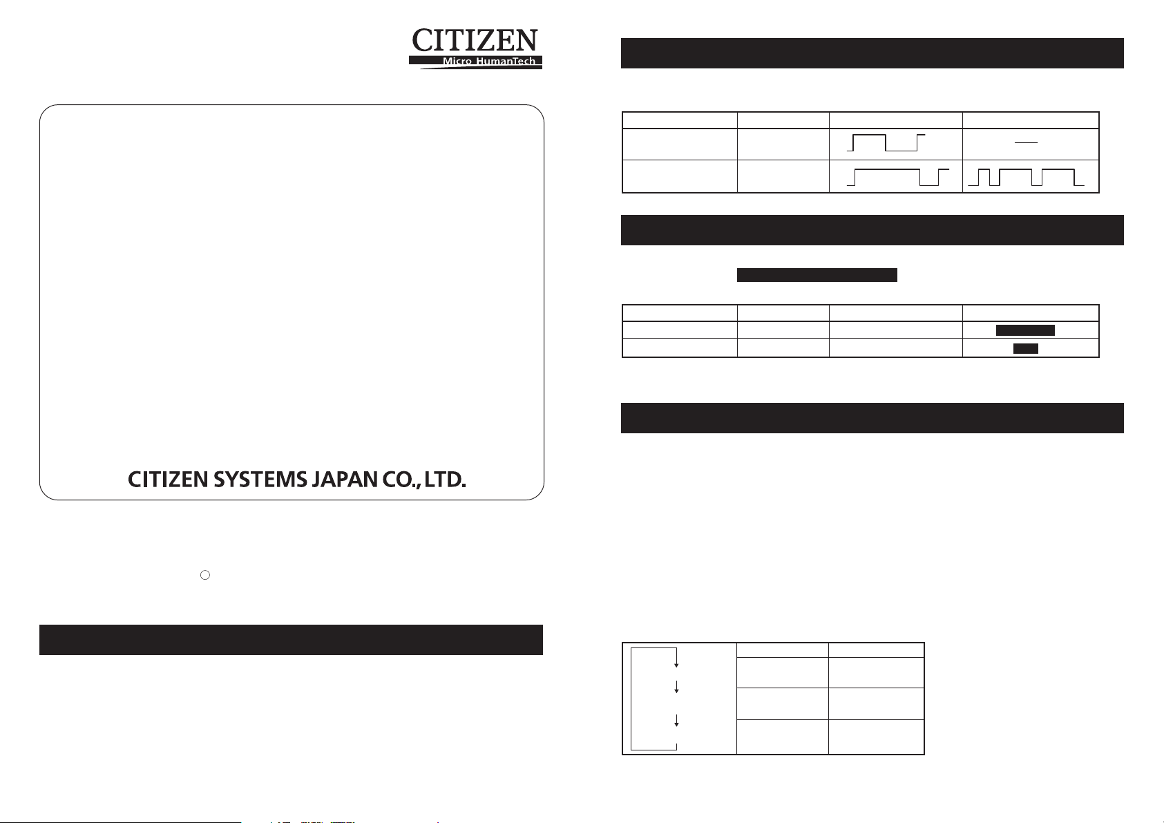
4.6 Error Indication
The following LED indications are added to CT-S4000L/CT-S4000DCL.
Status POWER LED ERROR LED Buzzer
Wait for cutting label OFF
Paper detection error OFF
User’s Manual
Refer to CT-S4000/CT-S4000DC User’s Manual of standard model when reading this manual.
Contents
1.1 Features
4.6 Error Indications
5.3 Manual Setting of Memory Switch
5.4 Selecting Paper Type
5.5 Adjusting Paper Sensor
5.6 Printing Paper
CITIZEN is a registered trade mark of Citizen Holdings Co., Japan
CITIZEN es una marca registrada de Citizen Holdings Co., Japón
Company names and product names in this manual are trademarks or
registered trademarks of relevant companies.
Copyright c 2007 by CITIZEN SYSTEMS JAPAN CO., LTD.
5.3 Manual Setting of Memory Switch
Functions of memory switches SW4-4 and SW4-5 of CT-S4000L/CT-S4000DCL are as
shown below. (The white-on-black characters are factory setting.)
Memory Switch Function 0 (OFF) 1 (ON)
SW4-4 Paper Select Thermal Roll BM.P/Lbl.P *
SW4-5 Position detect Black Mark Label
* The Print Width 660 dots is not available for printing a label paper.
* The memory switches SW2-8 will be ignored for Label.
5.4 Selecting Paper Type
Paper type selection is available by the combination of memory switches SW4-4 and
SW4-5 by the used of “Memory Switch Select Mode”. In addtion, the following
procedure is available.
1 Enter Selecting Paper Type mode.
1)Open the printer cover and remove paper. Pressing and holding the FEED button,
turn the printer power ON. The POWER LED starts blinking.
2)Release the FEED button and then close the printer cover. Buzzer sounds and
the paper type currently set is indicated by the LED on the operation panel.
2 Select Paper Type.
Press the FEED button to match the paper type loaded to the LED indications in the
table below. (Refer to the table below.)
1.1 Features
●High-speed printing at a maximum of 120 mm/sec
●2-dimensional barcode
●Label of nonstep 58 to 105 mm wide as well as 112 mm is usable
●Paper sensor sensitivity adjustment by variable resistor is adopted.
Label
Thermal paper roll
Black Mark paper
POWER LED ERROR LED
Green lit (OFF)
(OFF) Red lit
Green lit Red lit
Page 2
3Save the selected Paper Type to the Printer.
Open and close the printer cover. By this operation, selected paper type is stored in
the printer memory and the Selecting Paper Type mode is terminated.
Since then, "P.Length Set" of Memory switch 4-1 becomes disable.
When closing the printer cover during the setting a Black Mark paper or label paper
in the printer, paper length is measured, and the result will be printed out.
* If Paper Detection error occurs at the measurement of paper length, the printer
automatically enters Adjusting Paper Sensor mode. Adjust the sensor in
accordance with “5-5 Adjusting Paper Sensor”.
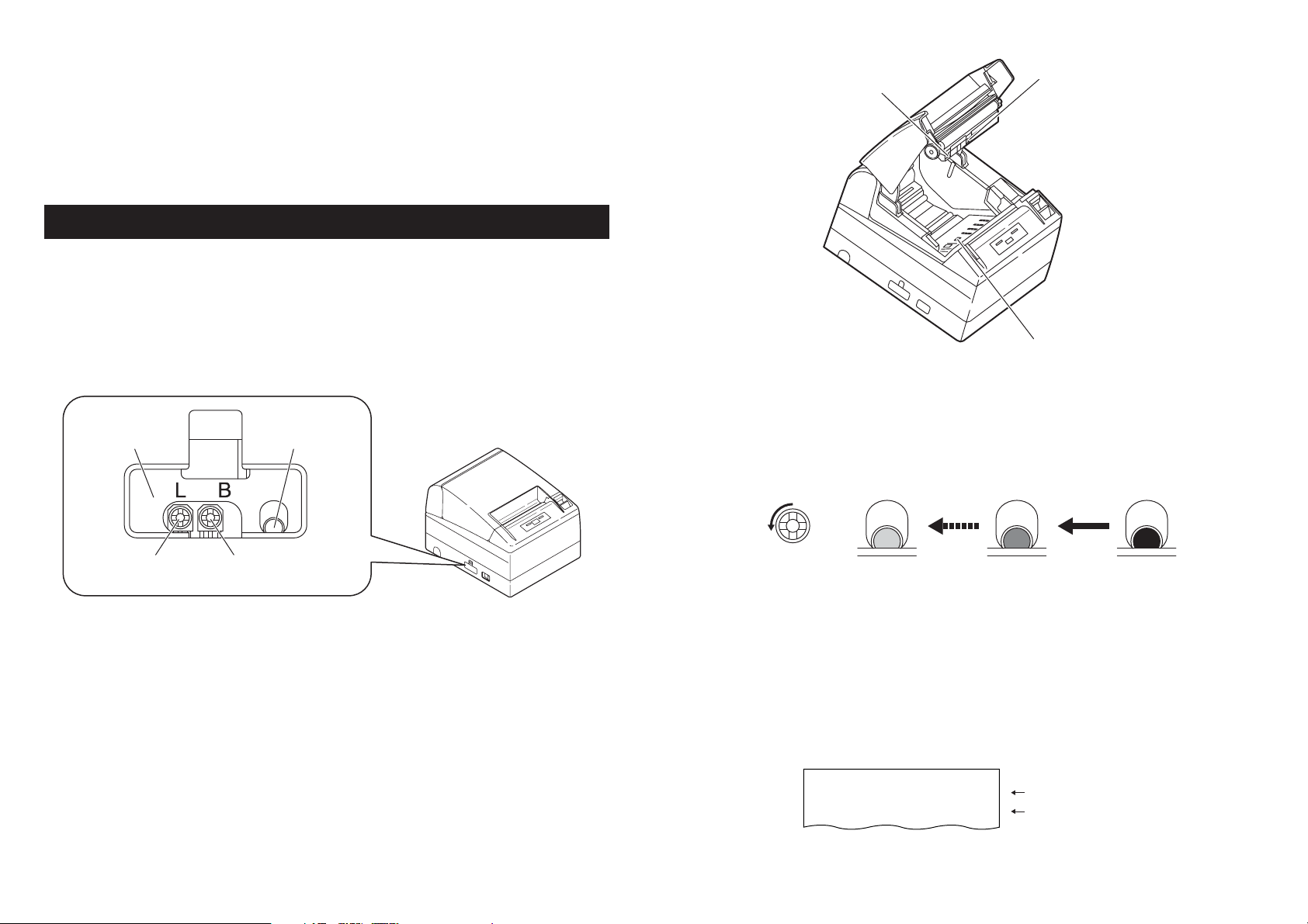
5.5 Adjusting Paper Sensor
Before using Black Mark paper (BM paper) or label, adjust the Paper sensor. First,
hold the lever at the upper end of the sensor adjustment control cover located at the
left of the Power switch and press the lever down and toward the front to remove the
cover from the printer.
As shown below, the most left one is a label paper sensor adjuster, the next is Black
Mark paper sensor adjuster, and the right one is a level indicator LED. Adjust them in
the following procedure.
Metal frame
Level indicator LED
Black Mark sensor
Label light receiving sensor
Label light emitting sensor
3Adjust Paper Sensor.
Turn the corresponding adjuster counterclockwise by using a tapered flat screwdriver.
Set the adjuster at the position where LED begins to change from orange to green.
Turning the adjuster
counterclockwise
Label paper sensor
adjuster
Black Mark paper
sensor adjuster
1 Enter Adjusting Paper Sensor mode.
Open the printer cover, remove paper, and then set the printer power switch to ON.
Here, POWER LED and ERROR LED go on with the buzzer sound. Then close the
printer cover while pressing the FEED button. The ERROR LED starts blinking with
the buzzer sound.
2 Set Paper to be adjusted to the Printer.
This printer has three types of built-in paper sensors.
In case of label, set it so that label is positioned on the label light receiving sensor
and label light emitting sensor. In case of Black Mark paper, set it so that the printable
portion (other than black mark) is positioned on the Black Mark sensor. With this
state kept, closing the printer cover causes ERROR LED to blink with the buzzer
sound.
Green Orange Red
* While turning the adjuster by the screwdriver, do not let the part of the
screwdriver touch the metal frame. Otherwise proper LED light color will not
be displayed while touching.
4Perform Paper Measuring operation
When the FEED button is pressed, label is fed and paper measuring is carried.If the
FEED button is presed during the paper measuring, the result will be printed out as
follows, and the printer memory switch will be initialized.
* The measuring result is a reference value
Label Length
Gap Length
< Example of label measuring result >
:
XXXmm
:
XXmm
showing a label length
showing a gap between labels
Page 3

5.6 Printing Paper
Also refer to the core dimension and notes of “5.2 Printing Paper” in User’s Manual of
standard model. Use print paper shown in the following table or the equivalent.
Paper type Product name
Recommended thermal label paper GG40/P22/G6B from Ojitac, HD75 from Nippon Paper,
150LA-1 from Ricoh
a) Label paper
A
BC
D
Full cut
Paper feeding
E
direction
position
HI
A
BC
D
Paper feeding
direction
Partial cut
position
HI
E
Unit: mm
Mark Item Dimensions
F
Printable area
JK
G
A Liner width 58 to 112
B Label width 54 to 108 + 0.5
C Left edge of label 2 + 0.5
D Print width 50 to 104
ETop margin 2 + 1
F Print length 21 to 296
GBottom margin 2 + 1
H
Cut position between labels
I Gap between labels 4 to 30
J Label length 25 to 300
K Label pitch I+J
1/2 x (Size I)
In the case of memory switch 4-8 set to 0 (OFF)
0
-1
_
_
_
F
Printable area
JK
G
In the case of memory switch 4-8 set to 1 (ON)
Mark Item Dimensions
A Liner width 58 to 112
B Label width 54 to 108 + 0.5
C Left edge of label 2 + 0.5
D Print width 50 to 104
ETop margin
F Print length 16 to 296
G Bottom margin 2 + 1
H
Cut position between labels
I Gap between labels 4 to 30
JLabel length 28 to 300
K Label pitch I+J
Unit: mm
0
-1
_
12 - (I-2) +1, min2
_
_
2 + 1
_
CAUTION!
Pay attention to the following when using Auto Cutter. Otherwise, a cutter lock or a cutter
failure may occur.
■ Set the cut length of paper to 25 mm or more.
■ When using label paper, cut the gap between labels (liner sheet). Do not cut the label paper
(tack paper).
■ Adusting the paper sensor must be carried when the type of liner is changed.
Page 4

b) Black mark paper (BM paper)
A
B
D
C
F
Black Mark (printed on the reverse)
Mark Item Dimensions
A Right edge of black mark 15 or more
BLeft edge of black mark 0 to 1.5
C Black mark height 5
D Cut position in black mark 2.5
ETop margin 6.5 / 12
F Black mark pitch 30 to 300
GBottom margin 9
Cut position
Printable area
Unit: mm
E
Paper feeding
direction
G
Top margin will be changed by the setting of the memory SW4-8.
In the case of 0 (OFF), the top margin is 6.5mm.
In the case of 1 (ON), the top margin is 12mm.
CAUTION!
■ PCS value of black mark must be 0.9 or more.
■ When using the black mark paper, consider the margin of +/- 2 mm for the print position
against the standard position and +/- 5 mm for print length.
■ Refer to the above drawing for the printable area and have enough margings specified in the
marks E and G. If the print data size is out of the printable area, the printer should skip to next
page.
TB74905-02F
1.02E-0705
Printed in Japan
 Loading...