

Page 1
LINE THERMAL PRINTER
MODEL CT-S4000/CT-S4000DC
User’s Manual
Mode d’emploi
Benutzerhandbuch
Manuale dell’utente
Manual de Usuario
Page 2

Declaration of Conformity
This printer conforms to the following Standards:
Low Voltage Directive 73/23/EEC, 93/68/EEC and the EMC Directive 89/336/EEC,
92/31/EEC, 93/68/EEC.
LVD:EN60950-1
EMC : EN55022 Class A
EN61000-3-2
EN61000-3-3
EN55024
This declaration is applied only for 230V model.
IMPORTANT: This equipment generates, uses, and can radiate radio frequency energy
and if not installed and used in accordance with the instruction manual, may cause
interference to radio communications. It has been tested and found to comply with
the limits for a Class A computing device pursuant to Subpart J of Part 15 of FCC
Rules, which are designed to provide reasonable protection against such interference
when operated in a commercial environment. Operation of this equipment in a
residential area is likely to cause interference, in which case the user at his own
expense will be required to take whatever measures may be necessary to correct
the interference.
CAUTION: Use shielded cable for this equipment.
Sicherheitshinweis
Die Steckdose zum Anschluß dieses Druckers muß nahe dem Gerät angebracht und
leicht zugänglich sein.
For Uses in Canada
This Class A digital apparatus complies with Canadian ICES-003.
This digital apparatus does not exceed the class A limits for radio noise emissions
from digital apparatus, as set out in the radio interference regulations of the Canadian
department of communications.
Pour L’utilisateurs Canadiens
Cet appareil numérique de la classe A est conforme à la norme NMB-003 du Canada.
Cet appareil numérique ne dépasse pas les limites de carégorie a pour les émissions
de bruit radio émanant d’appareils numériques, tel que prévu dans les réglements
sur l’interférence radio du départment Canadien des communications.
Page 3

ENGLISH
Page 4

GENERAL PRECAUTIONS
● Before using this product, be sure to read through this manual. After having read
this manual, keep it in a safe, readily accessible place for future reference.
● The information contained herein is subject to change without prior notice.
● Reproduction or transfer of part or all of this document in any means is prohibited
without permission from Citizen Systems.
● Note that Citizen Systems is not responsible for any operation results regardless
of missing, error, or misprinting in this manual.
● Note that Citizen Systems is not responsible for any trouble caused as a result of
using options or consumables that are not specified in this manual.
● Except explained elsewhere in this manual, do not attempt to service, disassemble,
or repair this product.
● Note that Citizen Systems is not responsible for any damage attributable to
incorrect operation/handling or improper operating environments that are not
specified in this manual.
● Data is basically for temporary use and not stored for an extended period of time
or permanently. Please note that Citizen Systems is not responsible for damage
or lost profit resulting from the loss of data caused by accidents, repairs, tests or
other occurrence.
● If you find loss of information, error, or uncertain matter, please contact your
Citizen Systems dealer.
● If you find any disordered or missing page(s), contact your Citizen Systems dealer
for replacement.
THE TABLE OF CONTENTS
1. GENERAL OUTLINE....................................................................7
2. EXPLANATION OF PRINTER PARTS........................................ 10
3. PREPARATION...........................................................................12
4. MAINTENANCE AND TROUBLESHOOTING ........................... 17
5. OTHER .......................................................................................22
CITIZEN is a registered trade mark of CITIZEN WATCH CO., LTD., Japan
CITIZEN es una marca registrada de CITIZEN WATCH CO., LTD., Japón
Company names and product names in this manual are trademarks or
registered trademarks of relevant companies.
Copyright c 2006 by CITIZEN SYSTEMS JAPAN CO., LTD.
— 1 —
Page 5
SAFETY PRECAUTIONS ... WHICH SHOULD BE STRICTLY OBSERVED
Before using this product for the first time, carefully read these SAFETY PRECAUTIONS. Improper
handling may result in accidents (fire, electric shock or injury).
In order to prevent injury to operators, third parties, or damage to property, special warning symbols
are used in the User’s Manual to indicate important items to be strictly observed.
● After having read this Manual,
● Some of the descriptions contained in this manual may not be relevant to some printer models.
The following describes the degree of hazard and damage that could occur if the printer is improperly
operated by ignoring the instructions indicated by the warning symbols.
keep it in a safe, readily accessible place for future reference.
WARNING
Neglecting precautions indicated by this symbol may result in fatal or serious injury.
CAUTION
Neglecting precautions indicated by this symbol may result in injury or damage to properties.
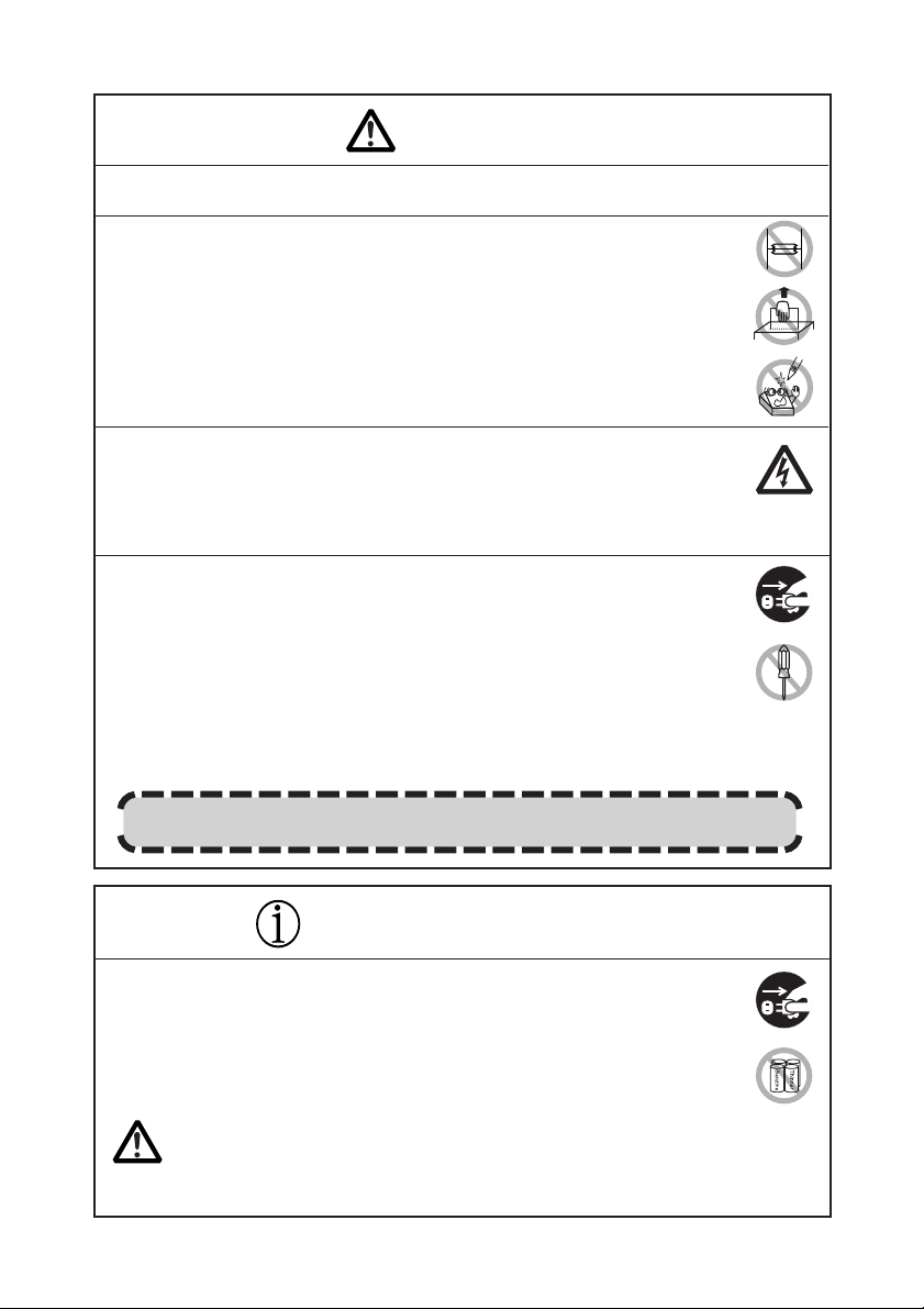
This symbol is used to alert your attention to important items.
This symbol is used to alert you to the danger of electric shock or electrostatic damage.
This symbol denotes a request to unplug the printer from the wall outlet.
This symbol is used to indicate useful information, such as procedures, instructions or the
like.
This symbol is used to indicate prohibited actions.
— 2 —
Page 6
WARNING
■ Do not use or store this product in a place where it will be exposed to:
* Flames or moist air.
* Direct sunlight.
* Hot airflow or radiation from a heating device.
* Salty air or corrosive gases.
* Ill-ventilated atmosphere.
* Chemical reactions in a laboratory.
* Airborne oil, steel particles, or dust.
* Static electricity or strong magnetic field.
• Neglecting these warnings may result in printer failure, overheating, emission of
smoke, fire, or electric shock.
■ Do not drop any foreign object nor spill liquid into the printer. Do not place any
object on the printer either.
■ Do not drop any metallic object such as paper clip, pin or screw into the printer.
■ Do not place a flower vase, pot or cup containing water on the printer.
■ Do not spill coffee, soft drinks or any other liquid into the printer.
■ Do not spray insecticide or any other chemical liquid over the printer.
•A metallic foreign object, if accidentally dropped into the printer, may cause printer
failure, fire, or electric shock. Should it occur, immediately turn the printer off,
unplug it from the supply outlet, and call your local Citizen Systems dealer.
Do not handle the printer in the following ways:
■ Do not allow the printer to sustain strong impacts or hard jolts (e.g., trampling,
dropping, striking with a hard edge).
■ Never attempt to disassemble or modify the printer.
• Neglecting to handle properly may result in printer failure, overheating, emission
of smoke, fire, or electric shock.
■ Install, use, or store the printer out of the reach of children.
• Electric appliances could cause an unexpected injury or accident if they are handled
or used improperly.
• Keep the power cord and signal cables out of the reach of children. Also children
should not be allowed to gain access to any internal part of the printer.
• The plastic bag the printer came in must be disposed of properly or kept away
from children. Wearing it over the head may lead to suffocation.
— 3 —
Page 7
WARNING
Please observe the following precautions for power source and power cord:
■ Do not plug or unplug the power cord with a wet hand.
■ Use the printer only at the specified supply voltage and frequency.
■ Check to make sure that the supply outlet from which the printer is powered has a
sufficient capacity.
■ Do not supply the printer from a power strip or current tap shared with other
appliances.
■ Do not plug the power cord into a supply outlet with dust or debris left on its plug.
■ Do not use a deformed or damaged power cord.
■ Do not move the printer while the printer power is on.
• Neglecting to handle properly may result in printer failure, emission of smoke, fire,
or electric shock.
• An overload may cause the power cord to overheat or fire or the circuit breaker to
trip.
■ Do not allow anything to rest on the power cord. Do not place the printer where
the power cord will be trampled on.
■ Do not use or carry the printer with its power cord bent, twisted, or pulled.
■ Do not attempt to modify the power cord unnecessarily.
■ Do not lay the power cord in the neighbor of a heating device.
• Neglecting these cautions may cause wires or insulation to break, which could
result in leakage, electric shock, or printer failure. If the power cord sustains
damage, contact your Citizen Systems dealer.
■ Do not leave things around the supply outlet.
■ Supply power to the printer from a convenient wall outlet, readily accessible in an
emergency.
• The printer may not be immediately shut down in an emergency.
■ Insert the power plug fully into the outlet.
■ If the printer will not be used for a long time, leave it disconnected from its supply
outlet.
■ Hold the plug and connector when plugging or unplugging the power cord or signal
cable after turning off the printer and the appliance connected to it.
— 4 —
Page 8
CAUTION
Do not use the printer under the following conditions.
■ A state subject to vibration or unstable state.
■ A state with this product slanted.
• Otherwise dropping may cause injury.
• Poor print quality may occur.
■ A state where the printer ventilation holes are obstructed by a nearby wall or other
equipment.
■ A state where any object is placed on the printer
■ A state where the printer is covered or wrapped by a cloth or bed clothing
• Be careful about internal heat buildup, which could cause fire and deform the case.
■ Avoid using the printer near a radio or TV set or from supplying it from the same
outlet as these appliances.
■ Avoid using the printer interconnected with a cable or cord that has no protection
against noise. (For interconnections, use shielded or a twisted pair of cables and
ferrite cores, or other anti-noise devices.)
■ Avoid using the printer with a device that is a strong source of noise.
• The printer may have an adverse effect on nearby radio or TV transmissions. There
may also be cases when nearby electrical appliances adversely influence the printer,
causing data errors or malfunction.
■ A state where this product is installed vertically or sidelong.
• Malfunction, failure, or electric shock may result.
■ Use the printer with its grounding post connected to a convenient grounding facility.
• If leakage occurs electric shock may result.
■ Do not connect the printer’s grounding post onto any of the following facilities:
* Utility gas piping
• A gas explosion could result.
* Telephone line ground
* Lightning rod
• If lightning strikes a large surge of current may cause fire or shock.
* Utility water pipes
• Plastic water pipes should not be used for grounding. (Those approved by
a Waterworks Department may be used.)
■ Before connecting or disconnecting the grounding lead to or from the printer, always
unplug it from supply outlet.
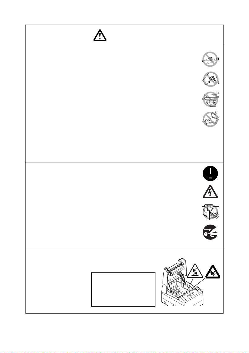
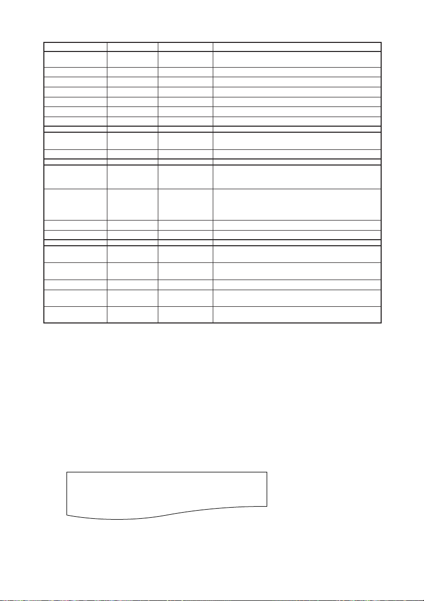
Caution label is attached on the position shown in
the following figure. Carefully read the precautions
in handling before using the printer.
THESE LABELS INDICATE THE
RISK OF ANY INJURY DUE TO
"HIGH TEMPERATURE" OF
THE PRINT HEAD AND "SAWTOOTHED EDGE" OF THE
MANUAL CUTTER.
— 5 —
Page 9
CAUTION
■ Do not transport this printer with the paper roll inside.
• Printer failure or breakage may occur.
To prevent possible malfunction or failure observe the following.
■ Avoid operating the printer without paper properly loaded.
■ Avoid the use of paper not complying with specifications.
• May result in poor print quality.
■ Avoid using torn pieces of paper or spliced with plastic adhesive tapes.
■ Avoid forcibly pulling already loaded paper by hand.
■ Avoid wedging the paper into the printer.
• May jam paper. To release, refer to “Removing Jammed Paper” in this manual.
■ Avoid using a sharp pointed device to operate panel keys.
■ Be sure to firmly insert the cable plug into its mating socket.
•A cross connection may damage the printer’s internal electronics or the host
system’s hardware.
■ Only use the printer with devices that have designated solenoid specifications for
the cash drawer interface connector.
• Neglecting this caution may result in malfunction or failure.
To prevent injury and printer failures from worsening, observe the following:
■ Do not touch the printing surface of the thermal head.
■ Do not touch any of the moving parts (e.g., paper cutter, gears, active electrical
parts) while the printer is working.
■ In case of trouble do not attempt to repair the printer. Ask Citizen Systems
service for repair.
■ Be careful that the printer cover does not entrap your hands or fingers.
■ Be careful with sharp edges on the printer. Do not allow them to injure you or
damage property.
• May result in electric shock, burn, or injury.
If the printer emits smoke, an odd smell, or unusual noise while printing, immediately
abort the current print session and unplug the printer from the supply outlet.
DAILY MAINTENANCE
Observe the following precautions for daily maintenance.
■ When cleaning the printer, always turn it off and unplug it from the supply outlet.
■ Use a soft, dry cloth for cleaning the surface of the printer case.
■ For severe stains, use a soft cloth slightly dampened with water.
■ Never use organic cleaning solvent such as alcohol, paint thinner, trichloroethylene,
benzene, or ketone. Never use a chemically processed cleaning cloth.
■ To remove paper dust, use a soft brush.
CAUTION
• The thermal head is at a dangerously high temperature immediately after printing.
Allow it to cool off before launching maintenance work.
— 6 —
Page 10

1. GENERAL OUTLINE
The CT-S4000/CT-S4000DC are thermal line printers designed for use with a broad array
of terminal equipment including data, POS, and kitchen terminals.
With extensive features, they can be used in a wide range of applications.
1.1 Features
● Versatile roll capacity with ability to use 80 mm, 82.5 mm and 112 mm wide paper
rolls.
● Can use paper roll with a maximum of 102 mm diameter.
● Drop-in paper loading mechanism facilitating easy paper handling and head cleaning.
● High speed (150 mm/s) printing.
● Equipped with USB interface as standard plus a choice of either a serial or parallel
interface.
● Replaceable interface board.
● High-speed parallel interface (Parallel interface model)
● Built-in cash drawer interface.
● Auto cutter mechanism provided as a standard.
● User customization such as memory switch setting are available.
● Page mode
● Registration of user-defined characters and logos into flash memory.
● Barcode printing
● 2-color printing is supported (When specified paper is used).
● Error indication is available with LED or buzzer.
● Can be installed on a wall by using the optional wall mounting kit.
— 7 —
Page 11
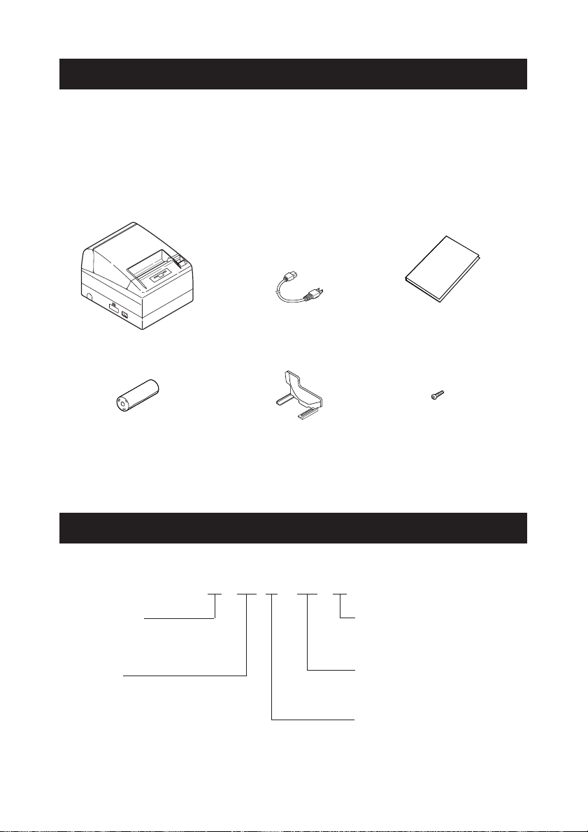
1.2 Unpacking
When unpacking the printer, confirm that the following are provided:
● Printer: 1
● AC power cord : 1 (for CT-S4000 only)
● User’s manual (This manual): 1
● Sample paper roll: 1 roll
● Partition: 1
● Screw: 1
User’s manual
(This manual)
CT-S4000
Sample paper roll
AC power cord
Partition Screw
1.3 Model Classification
The printer models are classified by the following designation method:
CT - S4000 RS E - BK -
Power supply
No marking: AC power type
(built-in power supply)
DC: DC power supply type
Interface
PA: IEEE1284 & USB
RS: RS-232C & USB
UB: USB only (Option)
Label/Black mark
No marking: Standard
L: Label
M: Black mark
Body case color
WH: Cool white
BK: Black
Character set, AC cable,
E: Europe
U: USA
— 8 —
Page 12
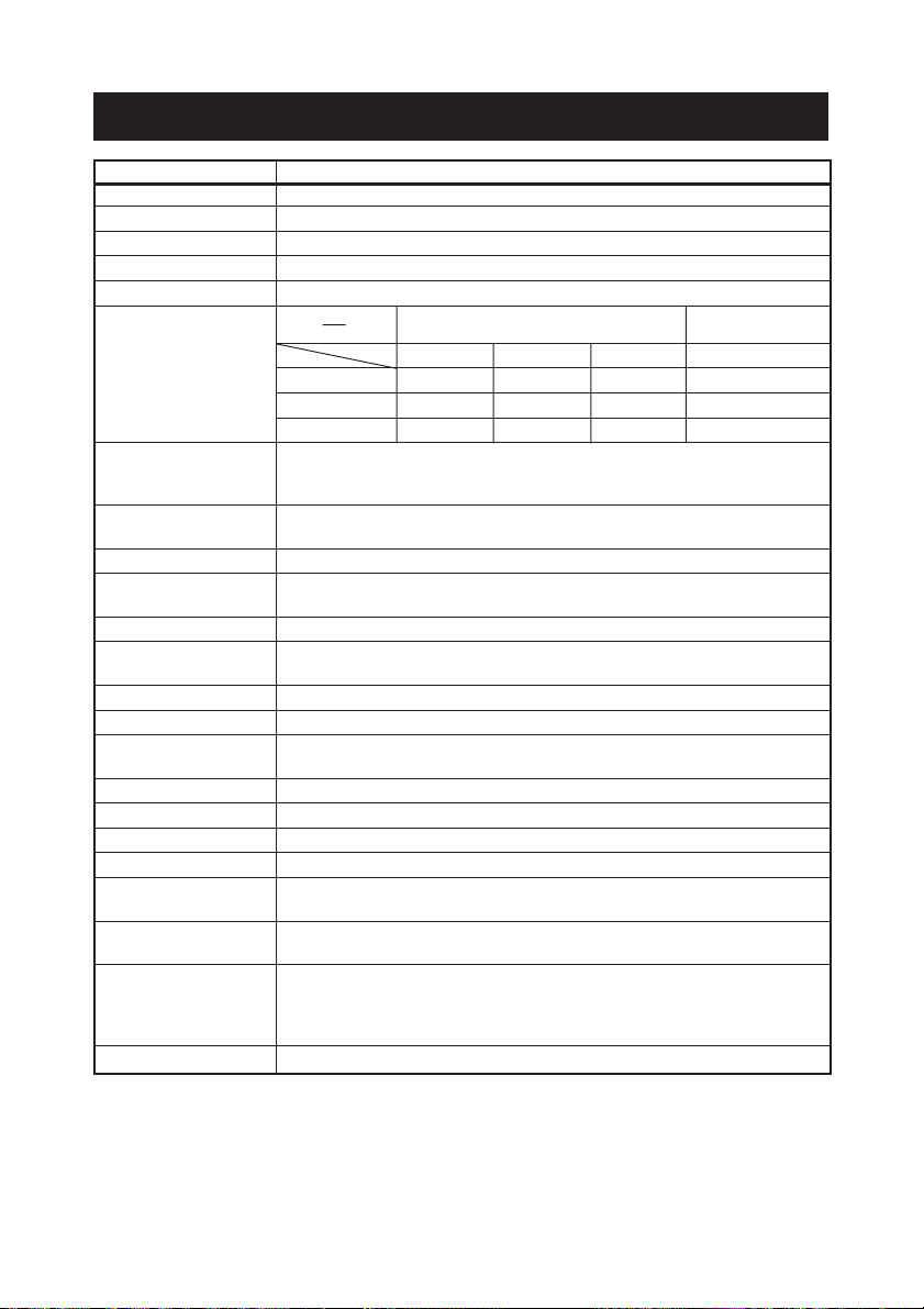
1.4 Basic Specifications
Item Specifications
Model CT-S4000 PA/RS/UB, CT-S4000DC PA/RS/UB
Print method Line thermal dot print method
Print width *1 112 mm/832 dots, 82.5 mm/660 dots, 80 mm/576 dots
Dot density 8 dots/mm (203 dpi) in holizontal & vertical
Print speed 150 mm/s (Fastest, print density 100 %), 1200 dot lines/s
Number of print
columns
*2
Font
Paper width
Font A 69 55 48 12 × 24
Font B 92 73 64 9 × 24
Font C 104 82 72 8 × 16
Character size *3 Font A: 1.50 × 3.00 mm
Font B: 1.13 × 3.00 mm
Font C: 1.00 × 2.00 mm
Character type Alphanumeric, International, PC437 PC850/852/857/858/860/863/864/
865/866/WPC1252/Katakana/Thai code 18
User memory
384 KB (Capable of registering user-defined characters and logos)
Types of bar code UPC-A/E, JAN (EAN) 13/8 columns, ITF, CODE 39, CODE 128,
CODABAR, CODE 93
Line spacing *4 4.23 mm (1/6 inch)
Paper roll Thermal paper roll: 112 mm/82.5 mm/80 mm ×Maximum φ102 mm
Paper thickness: 65-150 µm
Interfacing Serial (RS-232C compliant), Parallel (IEEE 1284 compliant), USB
Cash drawer interface 2 cash drawers are supported.
Input buffer 4K bytes/45 bytes (selectable) in Serial or Parallel interface, 16K bytes in
USB interface
Supply voltage AC100 to 240V, 50/60 Hz, 130VA / DC24V, 2.0A
Power consumption Approx. 70W (in normal prining)
Weight Approx. 2.3 Kg for CT-S4000, Approx. 2.0 Kg for CT-S4000DC
Outside dimensions 177 (W) × 213 (D) × 147 (H) mm
Operating temperature 5 to 45°C, 10 to 90% RH (No condensation)
and humidity
Storage temperature −20 to 60°C, 10 to 90% RH (No condensation)
and humidity
Reliability Print head life: 100 km, 1 × 10⁸ pulses (At normal temperature/
Auto cutter life:1 million cuts (At normal temperature/
Safety standard UL, C-UL, FCC Class A, TÜV-GS, CE Marking
Notes:
*1: When paper width is 112, 82.5, 80 mm
*2: The number of printable columns are selectable with a Memory Switch.
The number of columns in this table refers to typical model. Printer varies partly in the number
of columns depending on printer specifications.
*3: As each character size includes the space inside the character font, actual character looks
smaller.
*4: The line spacing is selectable with a command or Memory Switch. When the printer is turned
on, it will be slelecte with the memory switch.
Number of print columns
(columns)
112mm 82.5mm 80mm
0
−1
0
0
−1
−1
humidity with recommended paper used)
humidity with recommended paper used)
— 9 —
Dot configuration
(Dot)
Page 13
2.
EXPLANATION OF PRINTER PARTS
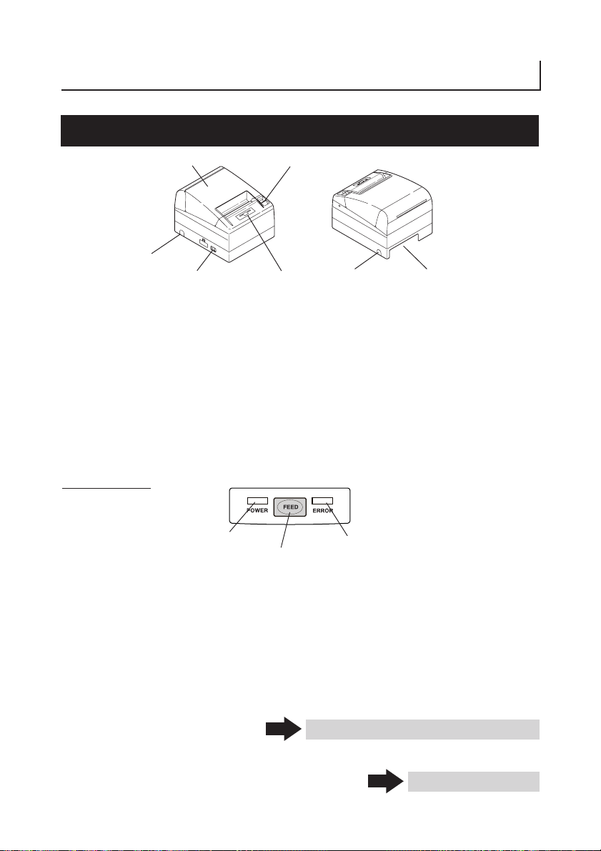
2.1 Printer Appearance
Printer cover
Side opening
Power switch
● Printer cover
Paper is loaded under this cover.
● Cover open button
To refill or replace paper, open the printer cover by pulling the cover open button
forward.
● Power switch
This switch turns the printer power ON/OFF.
● Side opening
The cables connected to the printer can be routed through this side opening. (Before
use, push the small plastic barrier on the cover until it brakes.)
Operation Panel
(Front view) (Rear view)
Cover open button
Operation panel
Side opening
Rear connector
POWER LED
● POWER LED
Illuminated when the printer power is on and off when the printer power is off. May
blink or light in a special mode or in case of failure.
● ERROR LED
Illuminated or blinks when paper is empty or in case of failure.
The interval length of blinking represents the type of error.
● FEED button
Pressing this button once causes the paper to feed one line. The longer the button is
pressed, the more paper is fed.
Pressing this button causes the paper to feed to the next Black Mark position in Black
Mark mode.
In case of auto cutter error, press the FEED button after removing the cause of the
error.
FEED button
— 10 —
ERROR LED
See 5.3 Manual Setting of Memory Switch
See 4.6 Error Indication
Page 14
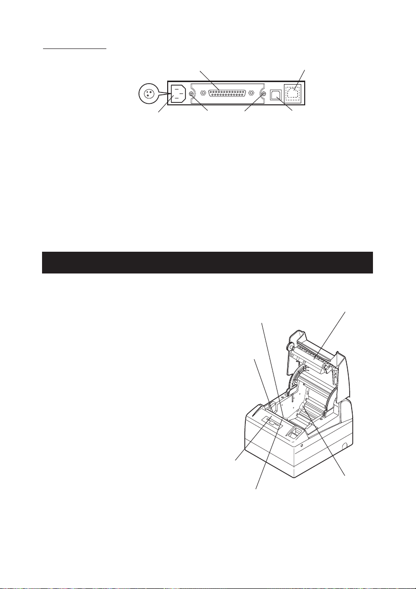
Rear Connectors
Power connector
(DC power supply type)
Interface connector
(Serial, parallel, etc.)
Cash drawer
kick-out connector
AC inlet
(AC power type)
Interface board
mounting screws
USB connector
● Interface connector (Serial, parallel, etc.)
Connects to the interface cable. A DIP switch is provided on the serial interface board.
● Cash drawer kick-out connector
Connects to the cable from the cash drawer.
● AC inlet (AC power type)
Connects to the AC power cord.
● Power connector (DC power supply type)
Connects to the cable from DC power source.
2.2 Printer Cover Inside
● Paper feed roller
Feeds paper as part of print
mechanism.
● Paper-near-end sensor
Detects near paper end, change
position in accordance with the outer
diameter of paper core.
● Auto cutter
Cuts the paper with a command at the
end of printing. Cutting method is
selectable between partial cut and full
cut with a command.
* Factory default of the memory SW4-8
is set to "Partial cut", so that a
command will be ignored.
Paper-end sensor
Print (thermal)
head
Paper feed roller
● Manual cutter
Tears the paper by hand.
● Print (thermal) head
Prints characters and/or graphic data
on thermal paper.
● Paper-end sensor
Stops printing when this sensor
detects paper end.
Auto cutter
— 11 —
Manual cutter
Paper-near-end
sensor
Page 15
3. PREPARATION
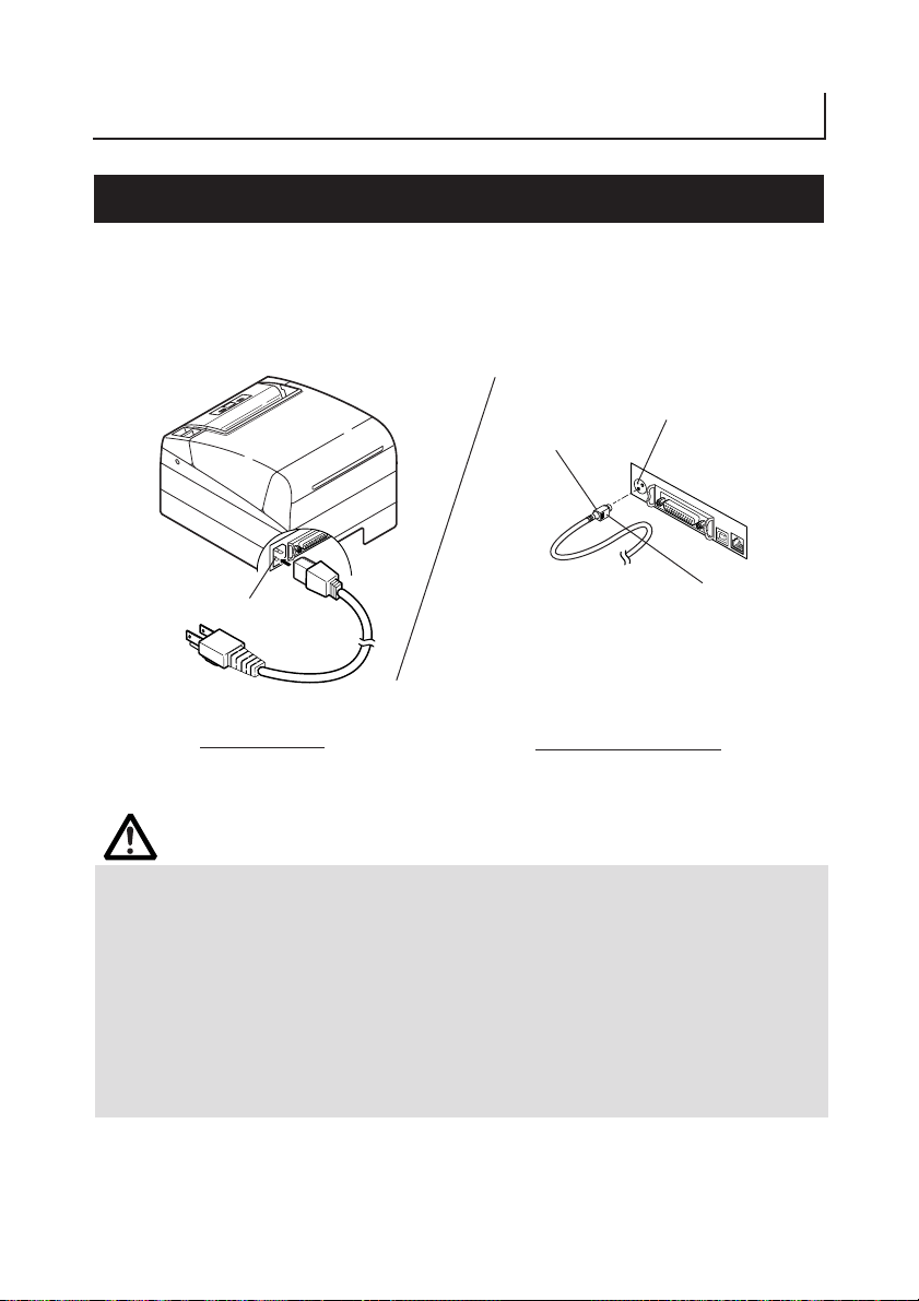
3.1 Connecting the AC Power Cord
1. Turn off the printer power switch.
2. For AC power type (with built-in power supply), connect the AC power cord
to the AC inlet at the back of the printer and plug the AC power cord into the
wall outlet.
Power connector
Cable connector
Flat side
AC inlet
AC power cord
AC power type
(built-in power supply)
DC power supply type
CAUTION!
■ When disconnecting a cable, DO NOT pull out by the cable. Always hold the plug.
■ Always keep the AC power supply away from other noise generating equipment.
■ DO NOT pull the AC power cord. Otherwise fire, electric shock, or power disconnection
may result.
■ If lightning is approaching, unplug the AC power cord from the wall outlet. Otherwise
fire or electric shock may result.
■ Keep the power cord away from heat generating appliances. Otherwise the shield of
power cord may be fused resulting in a fire or electric shock.
■ If the printer will not be used for a long time, leave it disconnected from its supply
outlet.
■ Avoid locating the AC power cord in places which may cause tripping or falling.
— 12 —
Page 16
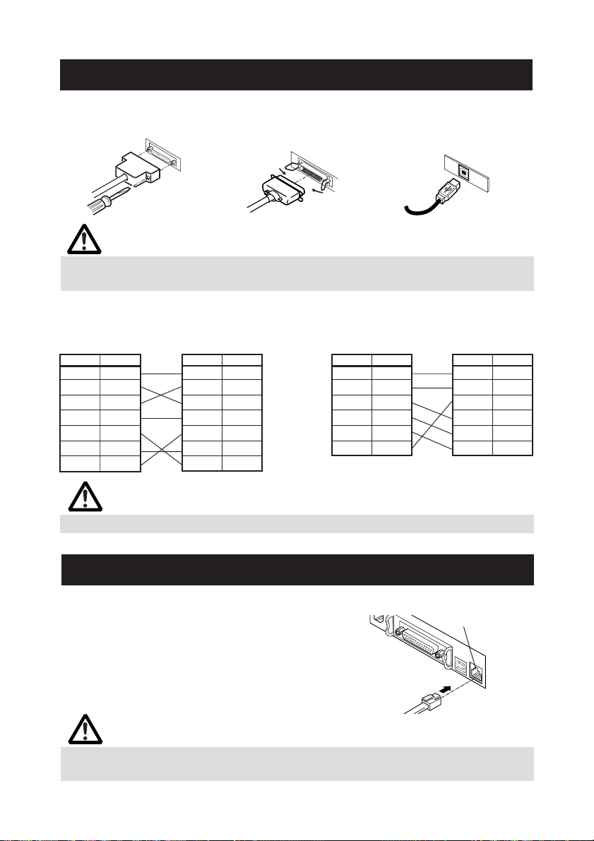
3.2 Connecting Interface Cables
Confirm that the power switch is OFF and connect the interface cable.
Orient the interface cable terminal correctly and insert it into the interface connector.
Serial Interface Parallel Interface
USB Interface
CAUTION!
■ When disconnecting the cable, always hold the connector.
■ Be careful not to insert the USB interface cable into the cash drawer kick-out connector.
For serial interface cable, use the one with the following connection.
25-pin - 25-pin cable 9-pin - 25-pin cable
PC
Signal Pin
FG 1
TXD 2
RXD 3
CTS 5
DSR 6
SG 7
DTR 20
Printer
Pin Signal
1FG
2TXD
3RXD
4RTS
6 DSR
7SG
20 DTR
PC
Signal Pin
RXD 2
TXD 3
DTR 4
SG 5
DSR 6
CTS 8
Printer
Pin Signal
2 TXD
3 RXD
4RTS
6 DSR
7SG
20 DTR
CAUTION!
Avoid locating the interface cable in places which may cause tripping or falling.
3.3 Connecting the Cash Drawer
1. Confirm that the power switch is OFF.
2. Confirm the top and bottom of the cash
drawer cable connector and insert it into
the cash drawer kick-out connector at the
back of the printer.
3. Screw the cash drawer's ground wire to
the body of the printer.
Cash drawer cable
connector
Cash drawer
kick-out connector
CAUTION!
DO NOT connect any other device than the specified cash drawer to the cash drawer
kick-out connector. (DO NOT connect a telephone line either.)
— 13 —
Page 17
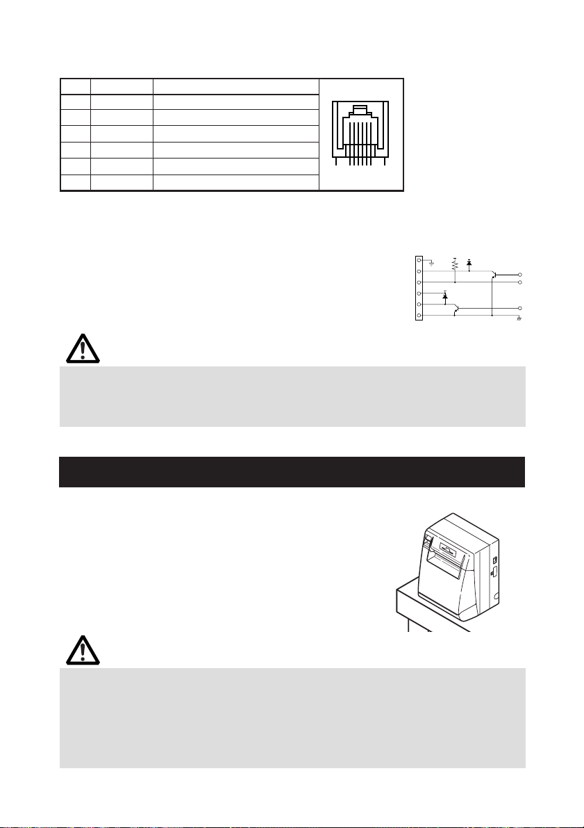
(1) Connector Pin Configuration
VDR
1
2
3
4
5
6
VDR
5V
No. Signal Function
1FG Frame Ground
2 DRAWER 1 Drawer 1 drive signal
3 DRSW Drawer switch input
4 VDR Drawer drive power supply
5 DRAWER 2 Drawer 2 drive signal
6 GND Common ground on circuits
61
Connector used:
TM5RJ3-66 (Hirose)
or equivalent
Applicable connector:
TM3P-66P (Hirose) or
equivalent
(2) Electrical characteristics
1) Driving voltage: 24 VDC
2) Driving current: Approx. 1A max. (shall not exceed 510
ms.)
3) DRSW signal: Signal levels: “L” = 0 to 0.5 V, “H” = 3 to 5 V
(3) DRSW signal
DRSW signal status can be tested with the DLE+EOT,
GS+a, or GS+r command or
at pin 34 on the parallel interface port.
(4) Drive Circuit (printer side)
CAUTION!
■ No output is produced while printing.
■ The cash drawers 1 and 2 cannot be driven simultaneously.
■ A solenoid used for the cash drawer should be of 24 Ω or more. The output current
should be kept at 1A or less; otherwise, breakdown or burning could occur.
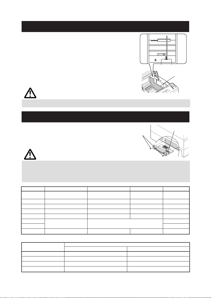
3.4 Installing the Printer
The printer can be installed horizontally, vertically, and on the wall.
At the time of shipment, the printer is set for horizontal
installation. To install the printer vertically or on the wall, the
following adjustments are required.
1. Adjustment of paper near-end sensor position (See
section 3.7)
2. Anti-slip rubber feet (for vertical setting)
3. Optional wall-mounting kit (for wall-mounting)
Ver tical position
CAUTION!
■ When used in vertical position, the printer ejects paper not to fall naturally even with
full cutting. Be careful in using the printer built in equipment, etc.
■ Ensure that the wall on which the printer is mounted has enough strength before
installation.
■ When using in horizontal setting, avoid cutting full. Otherwise, the cut paper may
drop into the cutter and may result in double cutting and narrow pieces of paper. This
may cause paper jam.
— 14 —
Page 18
80mm 82.5mm
→
→
3.5 Partition for Paper Roll
At the time of shipment, this partition is not installed.
1. Confirm that the power switch is OFF.
2. Open the printer cover.
3. Insert the partition into the slot and align it
with the scale inside of the printer which
meets the width of the paper roll used. When
using the 80mm or 82.5mm wide paper roll,
set the partition by using the accessory screw.
4. Change the setting of paper width by reffering
to the section 5.2, "Manual Setting of Memory
Switch".
Partition
Scales
Partition
CAUTION!
When using 112 paper roll, the partition is not used.
3.6 Setting DIP Switch
The DIP switch is present on the serial
interface board.
The function of each switch is as shown
below.
Interface board
mounting screws
DIP switch
CAUTION!
■ As for the setting of the serial interface, it gives priority to the setting of the memory
switch rather than the DIP switch as the factory default.
■ Consult with the dealer where the printer was purchased when the change of the DIP
switch setting is necessary.
Switch No. Function ON OFF
1
Communication condition
setting method
2 Hand shake XON/XOFF DTR/DSR OFF
3 Bit length 7 bits 8 bits OFF
4 Parity check With parity None OFF
5 Parity selection Even parity Odd parity OFF
6 OFF
Baud rate selection See Table below.
7 ON
8 INIT Reset Invalid OFF
Selecting baud rate
Baud Rate (bps)
2400 OFF OFF
4800 ON OFF
9600 OFF ON
19200 ON ON
DIP switch setting Memory switch OFF
67
setting
Switch No.
38400, 57600 and 115200 bps can also be selected by a command, etc.
— 15 —
InitialSettings
Page 19
3.7 Adjusting the Paper Near-end Sensor
1. Lightly push in the paper near-end sensor unit.
2. Move the paper near-end sensor unit to the right and left while keeping to
press it. The position to be set varies in accordance with the setting of the
printer, horizontal or vertical, or diameter of the paper roll as shown in the
following figure.
Sensor Position
**1 φ21.0 φ18.0
*2 φ24.5 φ21.5
3 φ28.0 φ25.5
Horizontal
Ver tical
* Factory setting for USA version
** Factory setting for other country version
4 φ31.5 φ28.0
5 φ35.0 φ32.0
5 φ21.0 φ18.0
4 φ24.5 φ21.5
3 φ28.0 φ25.5
2 φ31.5 φ28.0
1 φ35.0 φ32.0
Roll paper diameter at the
detection of near-end
Outer core diameter of
roll paper used
CAUTION!
■ Paper remaining differs by the type of paper roll used.
■ The external diameter of the paper roll is only for reference.
■ When a paper end error is detected incorrectly during using a paper roll with a honey-
comb type core, move the sensor position to the larger number.
Paper-near-end
sensor unit
— 16 —
5
4
3
2
1
Page 20
4.
MAINTENANCE AND TROUBLESHOOTING
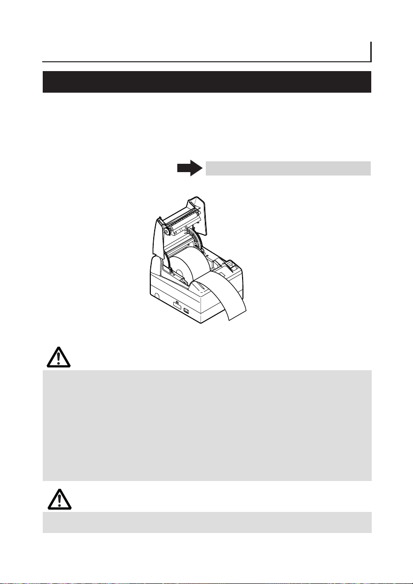
4.1 Setting/Replacing the paper roll
1. Pull the cover open button forward.
2. Open the printer cover.
3. Insert a paper roll with its print area facing down as shown in the figure and
pull out the paper end straightforward several cm (or inches) out of the
printer.
4. Firmly close the printer cover until a click can be heard.
See 5.3 Manual Setting of Memory Switch
CAUTION!
■ Always use the specified types of paper roll.
■ Confirm that the paper roll is set correctly.
■ When the paper is skewed and not extended straightforward from under the printer
cover, open the printer cover and adjust the paper correctly.
■
When the printer cover is opened after setting the paper, be sure to pull the paper
straightforward several cm (or inches) out of the printer, and then close the printer cover.
■ When closing the printer cover, press on the center part of the cover to close it firmly.
■ When setting paper, be careful not to have your finger injured by the manual cutter or
paper edge.
■ In the case of selecting "Valid" with memory SW4-3, the paper is fed and cut
automatically when the printer cover is closed.
WARNING
When opening the printer cover, DO NOT touch the print head or cutter blade. Otherwise,
burning or injury of hand may result.
— 17 —
Page 21

4.2 Removing Jammed Paper
1. Turn the printer power off.
2. Open the printer cover.
If the cutter blade remains protruded with paper jammed, do not force the
printer cover to open. Referring to the section 4.7, restore the blade to the
normal position and then open the cover.
3. Remove the jammed paper including any remaining paper shreds.
4. Turn on the printer. The auto cutter mechanism is initialized and the alarm
is cleared.
CAUTION!
■ If the cutter blade remains protruded with paper jammed, DO NOT open the printer
cover foribly and try to turn OFF and ON the printer power. If the cutter blade cannot
be restored, refer to the section 4.7.
■ The print head is hot immediately after printing. DO NOT touch it with your hand. DO
NOT touch the heating element of the head with a bare hand or metal object either.
4.3 Cleaning the Print Head
1. Turn the printer power off.
2. Open the printer cover.
3. Wait several minutes. Wipe off any debris on the heating element of the
head using a cotton swab soaked in ethyl alcohol.
Print (thermal) head
CAUTION!
The print head is hot immediately after printing. DO NOT touch it with your hand. DO
NOT touch the heating element of the head with a bare hand or metal object either.
— 18 —
Page 22
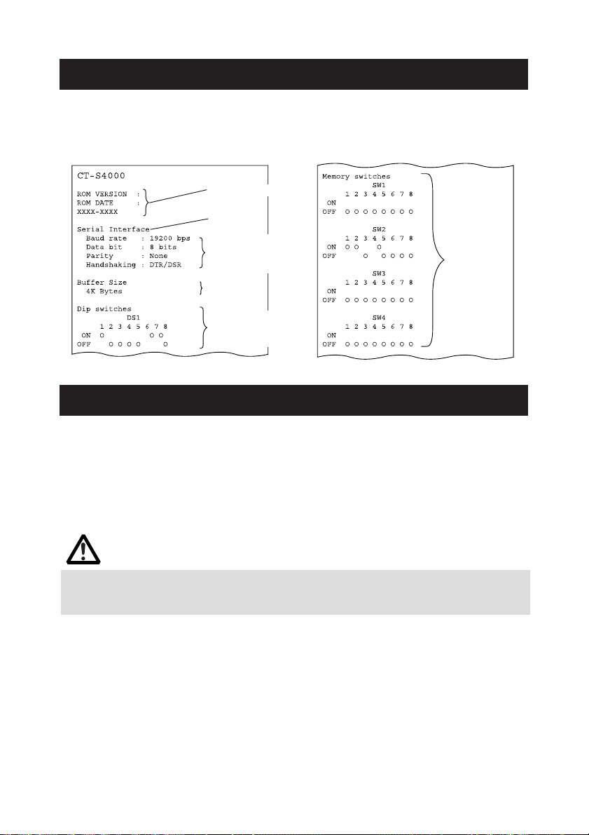
4.4 Self-printing
Insert paper into the printer. With the FEED button pressed and held, turn the printer
power on, keep the FEED button held for about 1 second, and then release the FEED
button. The printer starts self-printing. The printer prints model name, version, DIP
switch setting, memory switch setting, and built-in fonts.
Firmware version
Interface
Serial communication
condition (Only serial
interface model)
Buffer size
DIP switch setting
(Only serial interface
model)
Memory
switch
setting
4.5 Hexadecimal Dump Printing
This function is to print all received data in hexadecimal numbers. If problems such as
missing data, data duplication, etc. should occur, this function allows checking whether
or not the printer is receiving data correctly.
Load the paper into the printer and keep the printer cover open. With the FEED button
pressed and held, turn the printer power on and then close the printer cover. The printer
prints “HEX dump print mode” followed by the received data printed in hexadecimal
numbers and some characters.
CAUTION!
■ The printer prints “.” if there is no characters corresponding to data.
■ During hexadecimal dump, functions except some command will be disabled.
■ If print data DOES NOT cover a line, press the FEED button to print the line.
When you press the FEED button three times consecutively, or you turn the printer power
off, or the printer receives a reset signal from the interface, the hexadecimal dump printing
is terminated.
Print example
HEX DUMP PRINT MODE
1B 21 00 1B 20 04 41 42 43 44 .!.. .ABCD
45 46 47 48 49 4A 4B 4C 4D 4E EFGHIJKLMN
4F 50 0D 0A 31 32 33 0D 0A OP..123..
— 19 —
Page 23

4.6 Error Indication
● Paper end
Paper out is detected in two steps: paper near-end and paper end. ERROR LED will
light when the paper is empty. If paper end is detected, refill the paper. If the printer
cover is open, a paper-end is detected.
● Printer cover open
During printing, do not open the printer cover. If you open the printer cover accidentally,
the ERROR LED blinks. Check the paper, pull the paper straightforward several cm (or
inches) out of the printer, and then close the printer cover. Printing resumes
automatically. Sending a command to resume printing may be required depending on
the memory switch setting.
● Thermal head overheat
When you print dense characters or dark image, the head temperature rises. If the
head temperature exceeds a specified level, the printer stops printing operation and
waits till the head temperature is lowered. During waiting, the ERROR LED blinks.
When the head temperature is lowered, printing resumes automatically.
● Cutter lock
If the cutter blade stops operating due to paper jam or the like, the ERROR LED blinks.
Remove the cause of the trouble and press the FEED button. If the blade still does not
move and the printer cover cannot be opened, refer to the section 4.7.
● Black Mark detection error (in Black Mark mode)
When Black Mark cannot be detected even if a certain amount of paper feed is carried
out for Black mark detection, a Black Mark detection error occurs. If black detection
continues more than the specified period, a No Paper condition is assumed and the
same error as No Paper is indicated.
— 20 —
Page 24
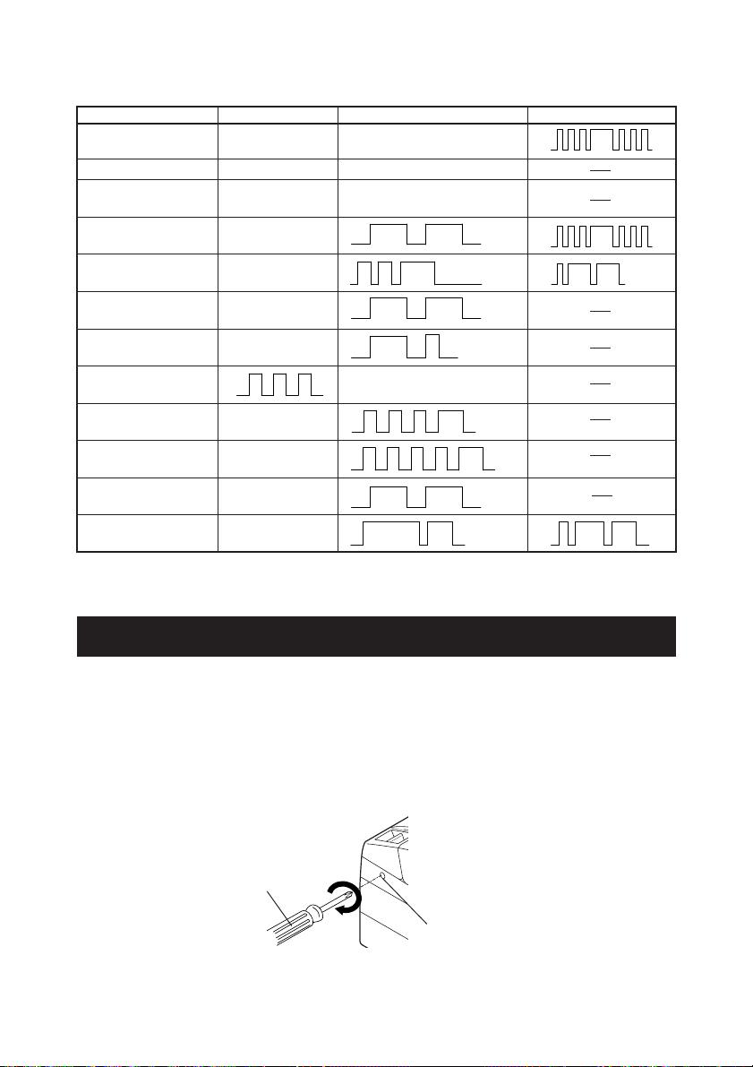
Lighting and blinking status of each error including the above is shown below.
Status POWER LED ERROR LED Buzzer
Paper-end Lights Lights
Paper near-end Lights Lights
Printer cover open Lights Lights
Printer cover open Lights
error *1
Cutter lock error Lights
Head overheat error Lights
Motor overheat error Lights
Memory check error Lights
Low voltage error Lights
High voltage error Lights
Macro execution Lights
wait *2
Black Mark detection Lights
error
*1: When the printer is printing.
*2: The ERROR LED may blink even in the execution of macro function.
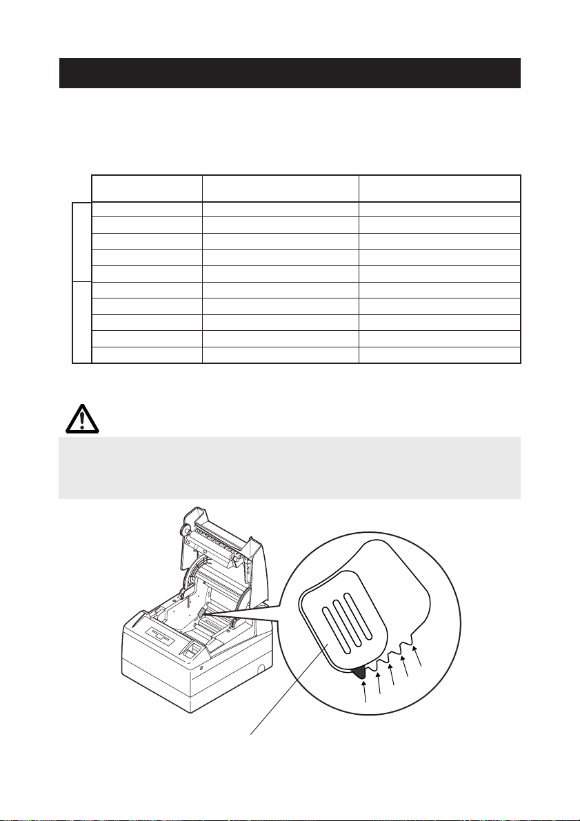
4.7
When the Paper Cover Cannot Be Opened
If the cutter blade remains protruded due to paper jam or for any abnormality, opening
the paper cover may be disabled. In this case, do not open the paper cover forcibly.
Insert a Phillips screwdriver (size #1) into the cutter lock releasing feed hole and turn it in
the direction of arrow (clockwise).
When you find that both ends of the blade reached the lowest position, stop turning the
screwdriver. Open the cover and follow the procedure of removing jam or other cause
of trouble.
Phillips screwdriver
Cutter lock
releasing feed hole
— 21 —
Page 25
5. OTHER
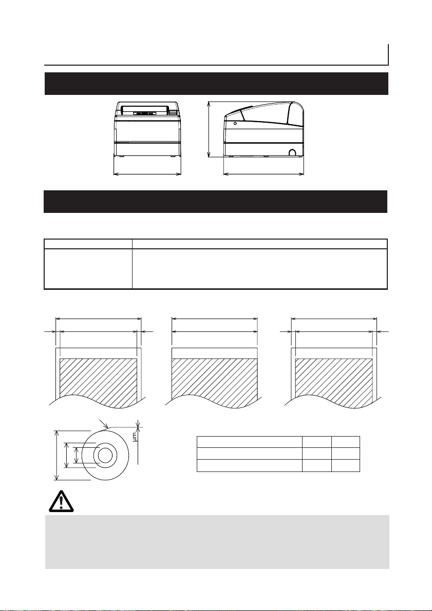
5.1 External Views and Dimensions
147
(Unit: mm)
177
213
5.2 Printing Paper
Use the print paper shown in the following table or the paper with equivalent quality.
Paper Type Product Name
Recommended thermal F230AA, P220AG, HP220A, HP220AB-1, P220AB, P220AE-1,
paper roll PB670 (Red/Black), PB770 (Blue/Black) from Mitsubishi Paper
Paper width 112
Maximum print area 104
44
Printing surface
d
D
φ102 or less
TF50KS-E2D from Nippon Paper
PD150R, PD160R from Ohji Paper
0
−1
65~150
Paper width 82.5
Maximum print area 82.5
Paper thickness (µm) 65-75 75-150
Core inner diameter d (mm) φ12 φ25.4
Core outer diameter D (mm) φ18 φ32
0
−1
Paper width 80
Maximum print area 72
44
0
−1
(Unit: mm)
CAUTION!
DO NOT use the following type of paper roll.
■ Paper with folds.
■ Paper with bent corners.
■ Paper pasted or glued to the core.
■ In-wound paper roll (print side in).
— 22 —
Page 26
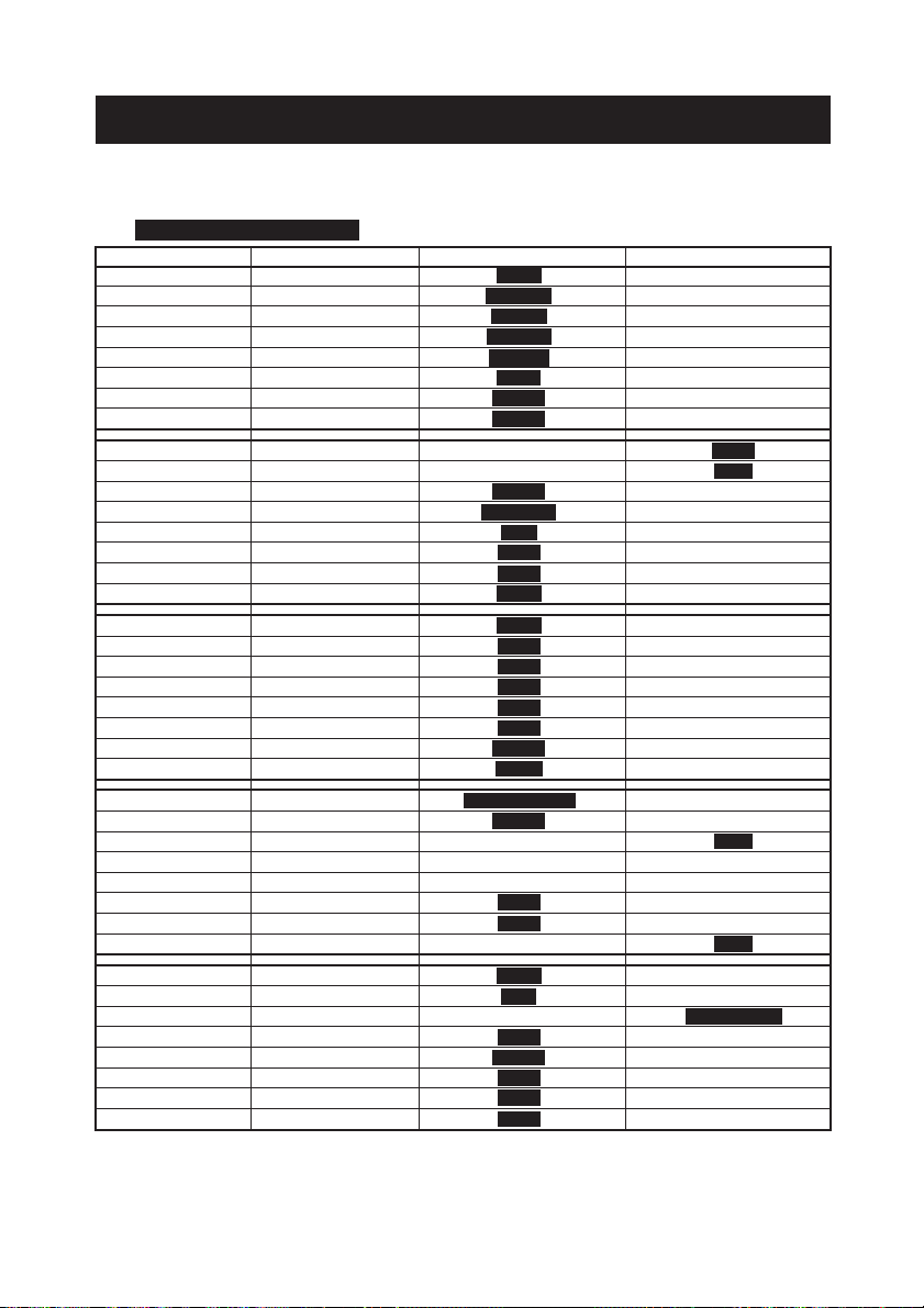
5.3 Manual Setting of Memory Switch
Memory switches can be set manually or by a command.
For manual setting, refer to the next page.
The function of each memory switch is shown in the following table.
(The white-on-black characters are factory setting.)
Switch No. Setting 0 (OFF) 1 (ON)
Memory SW1-1 Power ON Info Valid Not send
SW1-2 Buffer Size 4k bytes 45 bytes
SW1-3 Busy Condition Full/Err Full
SW1-4 Receive Error Print "?" No Print
SW1-5 CR mode Ignored LF
SW1-6 Reserved Fixed −
SW1-7 DSR Signal Invalid Valid
SW1-8 Init Signal Invalid Valid
Memory SW2-1 Reserved − Fixed
SW2-2 Auto Cutter Invalid Valid
SW2-3 Spool Print Invalid Valid
SW2-4 Full Col Print LineFeed WaitData
SW2-5 Resume aft PE Next To p
SW2-6 Reserved Fixed −
SW2-7 Reserved Fixed −
SW2-8 PNE Sensor Valid Invalid
Memory SW3-1 Resum Cttr Err Valid Invalid
SW3-2 Reserved Fixed −
SW3-3 Parallel 31 Pin Valid Invalid
SW3-4 Reserved Fixed −
SW3-5 Reserved Fixed −
SW3-6 Reserved Fixed −
SW3-7
SW3-8
Memory SW4-1 *3 P. Length Set Auto Measure Command
SW4-2 *3 Power on TOF Invalid Valid
SW4-3 Feed&Cut at TOF Invalid Valid
SW4-4 *3 Paper Select *1 Thermal Roll BM.P / Lbl.P
SW4-5 Position detect *2 Black Mark Label
SW4-6 Reserved Fixed −
SW4-7 Reserved Fixed −
SW4-8 Prtial Only Invalid Valid
Memory SW5-1 Buzzer Valid Invalid
SW5-2 Line Pitch 360 406
SW5-3 USB Mode Virtual COM Printer Class
SW5-4 Reserved Fixed −
SW5-5 Power OFF Info Invalid Valid
SW5-6 Reserved Fixed −
SW5-7 Reserved Fixed −
SW5-8 Reserved Fixed −
Notes:
*1: The factory setting of "Paper Select" will be different, depending on the model classfication.
*2: In the case of selecting the thermal roll with the SW4-4, the SW4-5 will not be available. The
SW4-5 will be set to "Black Mark" status for the Black Mark version printer.
*3: The SW4-1,4-2, 4-4, and 4-5 are available for the Black Mark version printer only.
CBM1000 Mode
Resum Open Err
Invalid Valid
Close Command
— 23 —
Page 27
Switch No. Setting Default Set Values
Memory SW7-1 Baud Rate 9600 bps 1200 bps, 2400 bps, 4800 bps, 9600 bps,
SW7-2 Data Length 8Bits 7Bits, 8Bits
SW7-3 Stop Bit 1Bit 1Bit, 2Bits
SW7-4 Parity NONE NONE, EVEN, ODD
SW7-5 Flow Control DTR/DSR DTR/DSR, XON/XOFF
SW7-6 DMA Control Valid Valid, Invalid
SW7-7
Memory SW8-1 Print Width 832dots
SW8-2 Paper Type 1 Color Normal 1 Color Normal, 2 Color Normal
Memory SW9-1 Code Page PC437 PC437/Katakana/PC850,858/PC860/PC863/
Memory SW9-2 Int'Char Set USA USA, France, Germany, England, Denmark,
Memory SW9-3* Kanji OFF ON, OFF
SW9-4* JIS/Shift JIS JIS JIS, Shift JIS
Memory SW10-1 Print Density 100% 70%, 75%, 80%, 85%, 90%, 95%, 100%, 105%,
SW10-2 Print Speed Level 9 Level 1, Level 2, Level 3, Level 4, Level 5,
SW10-3 ACK Timing Before Busy Before Busy, Same Period, After Busy
SW10-4 NV User 192K bytes 1K bytes, 64K bytes, 128K bytes, 192K bytes
SW10-5 NV Graphic 384K bytes 0 byte, 64K bytes, 128K bytes, 192K bytes,
* In this printer, Memory Switches 9-3 and 9-4 are not usable.
VCom Protocol
PC Setting PC Setting, DTR/DSR, XON/XOFF
19200 bps, 38400 bps, 57600 bps, 115200 bps
832dots(69 col.), 720dots(60col.), 660dots(55col),
576dots(48col.), 512dots(42col)
PC865/PC852/PC866/PC857/WPC1252/PC864/
Thai Code 18
Sweden, Italy, Spain, Japan, Norway,
Denmark 2, Spain 2, Latin America, Korea
Croatia, China
110%, 115%, 120%, 125%, 130%, 135%, 140%
Level 6, Level 7, Level 8, Level 9
256K bytes, 320K bytes, 384K bytes
Manual Setting of Memory Switch (Memory SW)
The memory switch can be selected, changed, or written by the combination of three
actions: pressing the FEED button, pressing and holding the FEED button, and opening
or closing the printer cover.
1. Entering memory switch setting mode.
Set paper in the printer and keep the printer cover open. With the FEED button
pressed and held, turn the printer power on, and then press the FEED button twice.
Close the cover. If the current settings of the memory switch etc. are printed, the
printer is now in the memory switch setting mode.
Memory SW (1) 00000000
(No indication for 0/1 with memory switch SW7 through SW10)
0: OFF state
1: ON state
— 24 —
Page 28

2. Selecting memory switch (MEMORY SWITCH SELECT MODE)
When the FEED button is pressed short (*1), printing occurs in the order of “Memory
SW1” → “Memory SW2” → “Memory SW3” → ......“Memory SW10” → “Save To
Memory” → “Memory SW1” → ...... repeatedly. When the memory switch you
want to change is reached, press and hold the FEED button (for more than 2 seconds).
3. Selecting each switch item
3-8 items are provided for setting in each switch. By pressing and holding the
FEED button long (*2), the printer goes to the next item and prints the current setting
of the item. Repeat pressing and holding untill the item you want to change is
reached.
Power ON notify setting (Valid )
(With memory switchSW7 through SW10, ERROR LED goes on only at the factory setting.)
OFF state: ERROR LED OFF
ON state: ERROR LED ON
4. Changing the setting
When the item you want to change is printed, press the FEED button short (*1).
The changed set value is printed. (When the change of the set value is repeated,
the original set value is recovered). When you press the FEED button long (*2), the
set value is accepted and then the printer goes to the next setting item.
5. Returning to the MEMORY SWITCH SELECT MODE (the above Item 2)
When the setting of the desired content is completed, open the printer cover and
then close the printer cover. This allows the printer to print the setting of the changed
memory switch.
6. Saving the setting and exiting the memory switch setting mode
Press the FEED button short (*1) to move to “Save To Memory”. Then press and
hold the FEED button. The printer prints the contents of new setting and exits the
memory switch setting mode to return to the normal standby state.
* Unless saving the setting is executed, the changed setting cannot be
enabled.
7. Initializing the memory switch
When you want to return the memory switch setting to the initial state, go to “Save
To Memory” in the above procedure. Here, open the printer cover and press and
hold the FEED button till buzzer sounds. This allows the printer to return to the
initial state.
* All the memory switches settings are returned to the factory set values.
*1: Press for less than 2 seconds *2: Press for more than 2 seconds
— 25 —
Page 29

FRANÇAIS
Page 30

PRÉCAUTIONS GÉNÉRALES
● Après l’avoir lu, le conserver dans un emplacement sûr, aisément accessible pour
une future référence.
● Les informations contenues dans ce manuel sont sujettes à des changements
sans préavis.
● La reproduction ou le transfert d’une partie ou de tout ce document par n’importe
quel moyen est interdite sans l’autorisation de Citizen Systems.
● Prière de prendre note que Citizen Systems n’est pas responsable de tout résultat
de fonctionnement indépendamment de manque, d’erreur ou de défaut
d’impression de ce manuel.
● Citizen Systems n’est pas responsable d’aucun problème causé par l’utilisation
des options ou produits consommables qui ne sont pas indiqués dans ce manuel.
● Sauf en cas de spécification contraire dans ce manuel, ne pas essayer d’entretenir,
démonter ou réparer cet appareil.
● Noter que Citizen Systems n’est pas responsable d’aucun dommage attribuable à
une opération/manipulation incorrecte ou à un environnement inexact d’opération
qui ne sont pas indiqués dans ce manuel.
● Les données sont prévues fondamentalement pour un usage provisoire, et ne
sont pas stockées pendant une longue période ou de manière permanente.
Veuillez noter que Citizen Systems n’est pas responsable des dommages ou de
toute manque de bénéfice résultant de la perte de données provoquées par des
accidents, réparations, essais ou toute autre occurrence.
● Si vous observez une perte d’informations, des erreurs ou des faits douteux,
veuillez contacter votre fournisseur Citizen Systems.
● Si vous trouvez n’importe quelle page désordonnée ou manquante, veuillez
contacter votre fournisseur Citizen Systems pour effectuer le remplacement.
TABLE DES MATIÈRES
1. PRÉSENTATION GÉNÉRALE ...................................................... 7
2. EXPLICATION DES COMPOSANTS DE L’IMPRIMANTE ........ 10
3. PRÉPARATION...........................................................................12
4. ENTRETIEN ET DÉPANNAGE................................................... 17
5. DIVERS ......................................................................................22
CITIZEN is a registered trade mark of CITIZEN WATCH CO., LTD., Japan
CITIZEN es una marca registrada de CITIZEN WATCH CO., LTD., Japón
Company names and product names in this manual are trademarks or
registered trademarks of relevant companies.
Copyright c 2006 by CITIZEN SYSTEMS JAPAN CO., LTD.
— 1 —
Page 31

PRÉCAUTIONS DE SÉCURITÉ
Veuillez lire attentivement ces PRÉCAUTIONS DE SÉCURITÉ avant d’utiliser l’appareil
pour la première fois.
La manipulation incorrecte peut avoir comme conséquence des accidents (incendie,
décharge électrique ou blessures). Afin d'éviter des blessures aux opérateurs, tiers, ou
des dommages à la propriété, des symboles d'avertissement spéciaux sont utilisés
dans le Mode d’Emploi pour indiquer les items importants à observer rigoureusement.
● Après avoir lu ce mode d’emploi, conservez-le dans un endroit sûr et facilement
accessible pour référence ultérieure.
● Certaines des descriptions contenues dans ce mode d’emploi peuvent ne pas
s’appliquer à certains modèles d’imprimantes.
Ce qui suit indique le degré de danger et de dommage encouru si l’imprimante n’est pas
utilisée correctement, sans tenir compte des instructions indiquées par les symboles
d’avertissement.
...
QUI DEVRAIENT ÊTRE OBSERVÉES RIGOUREUSEMENT
AVERTISSEMENT
Le non-respect des précautions indiquées par ce symbole peut provoquer des
blessures mortelles ou graves.
ATTENTION
Le non-respect des précautions indiquées par ce symbole peut provoquer des
blessures ou des dommages matériels.
Ce symbole sert à attirer votre attention sur des points importants.
Ce symbole sert à vous avertir d’un risque d’électrocution ou de dommage
électrostatique.
Ce symbole indique la nécessité de débrancher l’imprimante de la prise murale.
Ce symbole est utilisé pour indiquer l'information utile, telle que procédures,
instructions ou autres données dans ce genre.
Ce symbole sert à indiquer des actions interdites.
— 2 —
Page 32

AVERTISSEMENT
■ N’utilisez pas et ne rangez pas cet appareil dans un endroit où il sera exposé à :
* des flammes ou de l’air humide
* la lumière directe du soleil
* de l’air chaud ou aux radiations d’un appareil de chauffage
* de l’air salin ou des gaz corrosifs
* une atmosphère mal ventilée
* des réactions chimiques en laboratoire
* de l’huile, des particules d’acier ou de la poussière contenue dans l’air
* de l’électricité statique ou des champs magnétiques puissants
• Le non-respect de ces avertissements risque de provoquer des pannes de
l’imprimante, une surchauffe, des émissions de fumée, un incendie ou une
électrocution.
■ Ne laissez pas pénétrer des objets étrangers et ne renversez pas de liquide dans
l’imprimante. Ne placez pas non plus d’objet sur l’imprimante.
■ Ne laissez pas des objets métalliques comme des trombones, des épingles ou des
vis pénétrer dans l’imprimante.
■ Ne placez pas un vase ou un pot de fleurs, ou un verre contenant de l’eau sur
l’imprimante.
■ Ne renversez pas de café, de boissons fraîches ou tout autre liquide dans
l’imprimante.
■ Ne vaporisez pas d’insecticide ou tout autre produit chimique liquide sur
l’imprimante.
• Un objet métallique tombé accidentellement dans l’imprimante risque de provoquer
une panne, un incendie ou une électrocution. Dans ce cas, mettez immédiatement
l’imprimante hors tension, débranchez-la de la prise d’alimentation et faites appel
à votre revendeur local Citizen Systems.
Ne manipulez pas l’imprimante de la manière suivante:
■ Ne soumettez pas l’imprimante à des vibrations ou des chocs violents (par ex.
piétinement, chute ou coups avec un objet dur).
■ Ne tentez pas de démonter ou de modifier l’imprimante.
• Le non-respect des procédures correctes risque de provoquer une panne de
l’imprimante, une surchauffe, une émission de fumée, un incendie ou une
électrocution.
■ Installez, utilisez et rangez l’imprimante hors de la portée des enfants.
• Les appareils électriques risquent de provoquer des blessures ou des accidents
inattendus s’ils sont manipulés ou utilisés de manière incorrecte.
• Laissez le cordon d’alimentation et les câbles de signaux hors de la portée des
enfants. Les enfants doivent également être interdits d’accès aux pièces internes
de l’imprimante.
• Le sac en plastique dans lequel l’imprimante est emballée doit être mis au rebut
correctement et conservé hors de la portée des enfants. Une suffocation peut se
produire si le sac est mis sur la tête.
— 3 —
Page 33

AVERTISSEMENT
Observez les précautions suivantes pour l’alimentation électrique et le cordon
d’alimentation:
■ Ne branchez pas et ne débranchez pas le cordon d’alimentation avec les mains
mouillées.
■ Utilisez l’imprimante uniquement avec la tension d’alimentation et la fréquence
spécifiées.
■ Vérifiez si la prise sur laquelle l’imprimante est alimentée a une capacité
suffisante.
■ N’alimentez pas l’imprimante à partir d’un circuit d’alimentation ou d’une prise
de courant servant déjà à d’autres appareils.
■ Ne branchez pas le cordon d’alimentation dans une prise comportant de la
poussière ou des débris.
■ N’utilisez pas un cordon déformé ou endommagé.
■ Ne déplacez pas l’imprimante tandis que le courant de l’imprimante circule.
• Le non-respect des procédures correctes risque de provoquer une panne de
l’imprimante, une émission de fumée, un incendie ou une électrocution.
• Une surcharge risque de provoquer une surchauffe du câble d’alimentation ou
de déclencher le disjoncteur.
■ Ne posez pas d’objet sur le cordon d’alimentation. Ne placez pas l’imprimante
dans un endroit où le cordon risque d’être piétiné.
■ N’utilisez pas et ne transportez pas l’imprimante avec le cordon d’alimentation
plié, tordu ou tiré.
■ Ne tentez pas de modifier inutilement le cordon d’alimentation.
■ Ne placez pas le cordon d’alimentation à proximité d’un appareil de chauffage.
• Le non-respect de ces précautions risque de provoquer la rupture des fils ou de
l’isolation et de causer des fuites, une électrocution ou une panne de
l’imprimante. Si le cordon d’alimentation a subit des dommages, veuillez
contacter votre revendeur Citizen Systems.
■ Ne laissez pas d’objets autour de l’imprimante afin qu’elle soit toujours facile
d’accès.
■ Fournir l’alimentation à l'imprimante à partir d'une prise murale commode,
aisément accessible en cas d'urgence.
•L’imprimante peut ne pas être mise à l’arrêt immédiatement en cas d’urgence.
■ Introduisez à fond la fiche d’alimentation dans la prise.
■ Si l'imprimante ne sera pas utilisée pendant longtemps, la laisser déconnectée
de sa prise d’alimentation.
■ Tenez la prise et le connecteur quand vous effectuez le branchement ou le
débranchement du cordon du secteur ou du câble de communication après avoir
désactivé l’imprimante et l’appareil qui est connecté à elle.
— 4 —
Page 34

ATTENTION
Ne pas utiliser l’imprimante dans les conditions suivantes.
■ En condition sujette à vibration ou en condition instable.
■ Avec cet appareil incliné.
• Autrement une chute de la machine peut causer des dommages.
• Une qualité d'impression médiocre peut se produire.
■ En condition où les trous de ventilation de l’imprimante sont obstrués par un
mur voisin ou tout autre équipement.
■ Une condition dans laquelle un objet quelconque est placé sur l’imprimante.
■ Une condition dans laquelle l’imprimante est couverte ou enveloppée par un
tissu ou un drap de lit.
• Faire attention à l’accumulation interne de la chaleur, qui pourrait causer un
incendie et déformer le coffret.
■ Éviter d’utiliser l’imprimante près d’une radio ou d’un téléviseur ou de
l’alimenter à partir de la même prise que ces appareils.
■ Éviter d’utiliser l’imprimante connectée ensemble avec un câble ou un cordon
qui ne présente aucune protection contre les parasites. (Pour les interconnexions,
utilisez des câbles blindés ou torsadés et des noyaux en ferrite, ou d’autres
dispositifs anti-parasites).
■
Eviter d’utiliser l’imprimante avec un appareil produisant une source de bruit puissante.
•
L’imprimante peut avoir un effet négatif sur les transmissions radio ou télévisées.
Dans certains cas également, les appareils électriques proches peuvent influencer
l’imprimante et causer des erreurs de données ou des pannes.
■ En condition où cet appareil est installé verticalement ou latéralement.
• Un défaut de fonctionnement, une panne, ou une décharge électrique peuvent
se produire.
■ Utiliser l’imprimante avec sa fiche de terre connectée à une installation de mise à
la terre commode.
• Des électrocutions risquent de se produire en cas de fuites:
■
Ne pas connecter la fiche de terre de l’imprimante sur l’une des installations suivantes:
* Canalisation de gaz
• Une explosion de gaz peut se produire.
* Terre d’une ligne téléphonique
* Paratonnerre
• En cas de foudre, une surtension de courant importante peut provoquer un
incendie ou des chocs électriques.
* Canalisation d’eau
• Les tuyaux d’eau en plastique ne doivent pas être utilisés pour la mise à la
terre. (Ceux approuvés par le Département des Eaux peuvent être utilisés.)
■ Avant de brancher ou de débrancher le fil de terre de l’imprimante, débrancher
tout d’abord de la prise d’alimentation.
L’étiquette d’avertissement est
attachée sur la position
représentée sur la figure suivante.
Lisez soigneusement les
précautions pour la manipulation
avant d’utiliser l’imprimante.
CES ÉTIQUETTES
INDIQUENT UN RISQUE DE
BLESSURE CAUSÉE PAR
«HAUTE TEMPÉRATURE»
DE LA TÊTE D'IMPRESSION
ET DU «BORD DENTELÉ»
DU COUPOIR MANUEL.
— 5 —
Page 35

ATTENTION
■ Ne pas transporter cette imprimante avec un rouleau de papier à l'intérieur.
• Une panne ou une rupture de l’imprimante peut se produire.
Pour éviter les problèmes de fonctionnement ou les pannes éventuelles, observez ce qui suit:
■
Evitez de faire fonctionner l’imprimante sans rouleau de papier correctement chargé.
■ Evitez l’usage de papier non conforme aux spécifications.
• Ceci risque de fournir une qualité d’impression médiocre.
■
Evitez d’utiliser du papier froissé ou comportant des morceaux de ruban adhésif plastique.
■ Evitez de tirer à la main en forçant du papier déjà chargé.
■ Éviter de coincer le papier dans l'imprimante.
• Risque de bourrage de papier. Pour retirer le bourrage, reportez-vous à «Retrait
du papier coincé» dans ce mode d’emploi.
■ Evitez d’utiliser un dispositif pointu pour manipuler les touches du panneau.
■ Assurez-vous d’insérer fermement la prise du câble dans sa douille de connexion.
• Un mauvais branchement risque d’endommager les pièces électroniques internes
de l’imprimante ou le matériel du système hôte.
■ Utilisez l’imprimante uniquement avec des dispositifs ayant des spécifications de
solénoïde prévus pour le connecteur de l’ouverture du tiroir-caisse.
• Le non-respect de cette précaution risque de provoquer un problème de
fonctionnement ou une panne.
Pour éviter d’empirer les pannes ou les problèmes de l’imprimante, observez ce qui suit:
■ Ne touchez pas à la surface d’impression de la tête thermique.
■ Ne touchez pas aux pièces mobiles (par ex. le massicot, les engrenages, les pièces
électriques actives) lorsque l’imprimante fonctionne.
■ En cas de problème, ne tentez pas de réparer l’imprimante. Confiez-la au service de
Citizen Systems pour la réparation.
■ Faites attention à ce que le capot de l’imprimante ne coince pas vos mains ou doigts.
■ Prenez garde aux bords acérés de l’imprimante. Ils risquent de vous blesser ou de
provoquer des dommages matériels.
• Risque de provoquer une électrocution, des brûlures ou des blessures.
Si l’imprimante émet de la fumée, une odeur ou un bruit anormal pendant l’impression,
abandonnez immédiatement le travail d’impression en cours et débrancher l’imprimante
de la prise murale.
ENTRETIEN JOURNALIER
Observez les précautions suivantes pour l’entretien quotidien.
■ Pour nettoyer l’imprimante, mettez-la toujours hors tension et débranchez-la de la
prise murale.
■ Utilisez un chiffon doux et sec pour nettoyer la surface du boîtier de l’imprimante.
■ Pour les taches tenaces, utilisez un chiffon doux légèrement imbibé d’eau.
■ N’utilisez jamais d’agent de nettoyage organique comme de l’alcool, un diluant
pour peinture, ou du benzène.
■ Pour enlever la poussière de papier, utiliser une brosse souple
ATTENTION
• La tête thermique conserve une température dangereusement élevée
immédiatement après usage. Ne la touchez pas avant qu’elle n’ait refroidi.
— 6 —
Page 36

1. PRÉSENTATION GÉNÉRALE
Les modèles CT-S4000/CT-S4000DC sont compacts, thermique et silencieux. Ils sont
utilisés dans diverses applications comme, les terminaux point de vente, les systèmes
de date, les imprimantes situées en cuisine…
1.1 Caractéristiques
● La capacité de rouleau versatile avec possibilité d'utiliser des rouleaux de 80 mm, 82.5
mm et 112 mm de papier de largeur.
● Peut utiliser les rouleaux de papier avec un diamètre maximum de 102 mm.
● Mécanisme “Drop-in” facilitant la manipulation aisée du papier et le nettoyage de la
tête.
● Impression à grande vitesse (150 mm/s)
● Doté de l'interface USB en standard, plus un choix d'une interface sérielle ou parallèle.
● Interface de communication remplaçable
● Interface parallèle à grande vitesse (modèle d'interface parallèle)
● Interface de tiroir-caisse incorporée.
● Mécanisme de découpe automatique fourni en standard.
● La personnalisation par l'utilisateur par memory switch est disponible.
● Mode Page.
● Enregistrement des caractères utilisateur et des logos définis par l'utilisateur dans la
mémoire flash.
● Impression de code à barres
● Impression bicolore possible (Avec le papier spécifique).
● L'indication des erreurs est disponible avec la LED ou le buzzer.
● Peut être installé sur un mur en utilisant le kit en option de fixation murale.
— 7 —
Page 37

1.2 Déballage
Vérifiez que les composants suivants sont dans le paquet lorsque vous déballez l’imprimante:
● Imprimante: 1
● Cordon secteur: 1 (Seulement pour CT-S4000)
● Mode d’emploi (ce manuel): 1
● Rouleau de papier échantillon: 1 rouleau
● Adaptateur: 1
● Vis: 1
Mode d’emploi
(ce manuel)
Vis
CT-S4000
Rouleau de papier
échantillon
Cordon secteur.
Adaptateur
1.3 Classification des modèles
Les modèles d’imprimante sont classifiés selon la méthode de désignation suivante:
CT - S4000 RS E - BK -
Alimentation
Aucune marque: Type
alimentation c.a.
(alimentation intégrée)
c.c.: Type d'alimentation c.c.
Interface
PA: IEEE1284 & USB
RS: RS-232C & USB
UB: seulement USB
(Option)
Étiquette/Marque noire
Aucune inscription:
Standard
L: Étiquette
M: Marque noire
Couleur du boîtier
WH: Blanc
BK: Noir
Jeu de caractères, câble à
c.a.,
E: Europe
U: États-Unis
— 8 —
Page 38

1.4 Spécifications de base
Rubrique Caractéristiques
Modèle CT-S4000 PA/RS/UB, CT-S4000DC PA/RS/UB
Méthode d’impression Méthode d’impression thermique en lignes
Largeur d’impression
Densité de point 8 × 8 points/mm (203 dpi) en positions horizontale et verticale
Vitesse d’impression
Nombre de colonnes
d’impression
Taille des caractères *3 Police A: 1.50 × 3.00 mm
Type de caractère Alphanumérique, international, PC437/850/852/857/858/860/863/864/
Mémoire d’utilisateur
Types de code à barres UPC-A/E, JAN (EAN) 13/8 colonnes, ITF, CODE 39, CODE 128, CODABAR,
Espacement de lignes
Rouleau de papier Rouleau de papier thermique: 112 mm/82.5 mm/80 mm
Interfaces Série (conforme à RS-232C), Parallèle (conforme à IEEE 1284), USB
Interface du tiroir-caisse
Tampon d’entrée 4 Koctets/45 octets (sélectionnable) dans l'interface sériale ou parallèle,
Tension d’alimentation C.A.100 à 240V, 50/60 Hz, 130VA/C.C.24V, 2,0A
Consommation électrique
Poids CT-S4000:Environ 2.3 kg, CT-S4000DC:Environ 2.0 kg
Dimensions externes 177 (l) × 213 (p) × 147 (h) mm
Température et humidité
de fonctionnement
Température et humidité
de stockage
Fiabilité Durée de vie de la tête d’impression: 100 km, 1 × 10
Standard de sécurité UL, C-UL, FCC Class A, TÜV-GS, CE Marking
Notes:
*1: Quand la largeur de papier est de 112, 82.5, 80 mm
*2: Le nombre de colonnes imprimables peut être sélectionné avec le commutateur de mémoire.
Le nombre de colonnes dans ce tableau se rapporte à un modèle typique. Le nombre de colonnes de
l'imprimante varie en partie selon les caractéristiques de l’imprimante même.
*3: Comme chaque taille de caractère comprend l'espace à l'intérieur de la police de caractères, le
caractère effectif semble plus petit.
*4: L’interlignage est sélectionnable avec une commande ou un commutateur de mémoire. Quand
l'imprimante est mise en marche, elle sera sélectionnée avec le commutateur de mémoire.
*1 112 mm/832 points, 82.5 mm/660 points, 80 mm/576 points
150 mm/s (Le plus rapide, densité d'impression de 100 %), 1200 lignes de points/s
Nombre de colonnes
*2
Police
Largeur de papier
d'impression (colonnes)
112mm 82.5mm 80mm
Police A 69 55 48 12 × 24
Police B 92 73 64 9 × 24
Police C 104 82 72 8 × 16
Police B: 1.13 × 3.00 mm
Police C: 1.00 × 2.00 mm
865/866/WPC1252/Katakana/ Thaï 18
384 KB (capable d’enregistrer les caractères et les logos définis par l’utilisateur)
CODE 93
*4 4,23 mm (1/6 pouce)
× Maximum φ102 mm
0
−1
Épaisseur papier: 65-150 µm
2 tiroirs-caisse sont supportés.
16K octets dans l'interface USB
Environ 70 W (en cas d’impression normale)
De 5 à 45°C, 10 à 90% RH (pas de condensation)
De –20 à 60°C, de 10 à 90% RH (pas de condensation)
(À température/humidité normale en utilisant le papier recommandé)
Durée de vie du massicot automatique: 1.000.000 découpes
(À température/humidité normale en utilisant le papier recommandé)
— 9 —
0
−1
Configuration de
points (point)
0
−1
8
impulsions
Page 39

2.
EXPLICATION DES COMPOSANTS DE L’IMPRIMANTE
2.1 Apparence extérieure de l’imprimante
Capot de l’imprimante
● Capot de l’imprimante
Le papier est chargé sous
ce capot.
● Levier d’ouverture du
capot
Pour remplir ou remplacer
le papier, ouvrir le capot de
l’imprimante en tirant le
levier d’ouverture du capot
en avant.
● Interrupteur d’alimentation
Cet interrupteur permet de mettre l’imprimante sous tension/hors tension.
● Ouverture latérale
Les câbles reliés à l'imprimante peuvent être conduits par cette ouverture latérale.
(Avant l’usage, pousser la petite barrière en plastique sur le couvercle jusqu'à ce qu'elle
freine).
Panneau de commande
LED ALIMENTATION
● LED ALIMENTATION
S’illumine si l’imprimante est en mode marche- et s’éteint lorsque le courant de
l’imprimante est coupé. Elle peut clignoter ou s’illuminer en mode spécial ou en cas
de panne.
Ouverture
latérale
Interrupteur
d’alimentation
(Vue de face) (Vue arrière)
Interrupteur d’avance
papier (FEED)
Levier d’ouverture
du capot
Panneau de
commande
LED ERREUR
Ouverture
latérale
Connecteur
arrière
● LED ERREUR
S’illumine ou clignote quand il n’y a plus de papier ou en cas de panne.
La longueur d'intervalle du clignotement représente le type d'erreur.
● Interrupteur d’avance papier (FEED)
Appuyer sur cet interrupteur une fois pour faire avancer le papier d’une ligne. Plus la
pression sur cet interrupteur est longue, et plus le papier avancera.
Appuyer sur cette touche pour alimenter le papier vers la prochaine position de Marque
Noire [Black Mark] en mode de Marque Noire.
Voir le Paragraphe 5.3 Réglage manuel du commutateur de mémoire
En cas d'erreur du dispositif de découpe automatique, appuyer sur l’interrupteur
ALIMENTATION après avoir éliminé la cause de l'erreur.
Voir le Paragraphe 4.6 Indication des erreurs
— 10 —
Page 40

Connecteurs postérieurs
Connecteur d'interface
(série, parallèle, etc.)
Connecteur de tiroir-caisse
d’alimentation (type
Connecteur
d'alimentation c.c.)
Prise d’entrée
c.a. (type à c.a.)
Vis de support du
panneau d’interface
Connecteur USB
● Connecteur d'interface (série, parallèle, etc.)
Connecté au câble d'interface. Une série de commutateurs (dip switch) est fourni sur
l’interface série.
● Connecteur de tiroir-caisse
Connecte au câble du tiroir-caisse.
● Prise d’entrée c.a. (version DC)
Connecte au cordon c.a.
● Connecteur d’alimentation (type d'alimentation c.c.)
Connecte au câble à partir de la source d’alimentation c.c.
2.2 Intérieur du capot de l’imprimante
● Rouleau d’entraînement du papier
Alimente le papier comme pièce du
mécanisme d’impression.
● Capteur « presque de fin de papier »
Détecte l'extrémité du papier, changer
sa position selon le diamètre extérieur
du mandrin de papier.
● Mécanisme de découpe automatique
Coupe le papier avec une commande
à la fin de l'impression. La méthode
de découpage peut être sélectionnée
entre la coupe partielle et la coupe
totale avec une commande.
* Le réglage de défaut d'usine de la
mémoire SW4-8 s’effectue sur «Coupe
partielle» [Partial cut], de sorte qu'une
commande sera ignorée.
Capteur de fin de
papier
Tête (thermique)
d'impression
Rouleau d’entraînement
du papier
● Coupoir manuel
Coupe le papier manuellement.
● Tête (thermique) d'impression
Imprime les caractères d'impression
et/ou données graphiques sur le papier
thermique.
● Capteur de fin de papier
Interrompt l'impression quand ce
capteur détecte l'extrémité du papier.
Mécanisme
de découpe
automatique
— 11 —
Capteur « presque
de fin de papier »
Coupoir manuel
Page 41

3. PRÉPARATION
3.1
Cordon
d’alimentation c.a.
Branchement du cordon à c.a.
1. Mettez l’imprimante hors tension.
2. Pour la version adaptateur secteur uniquement : Avec le côté plat du
connecteur du câble de l’adaptateur secteur face vers le haut, insérez le
connecteur du câble dans le connecteur d’alimentation à l’arrière de
l’imprimante.
Connecteur d’alimentation
Connecteur du
câble
Entrée c.a.
Type d'alimentation c.a.
(Type alimentation intégrée)
Type d'alimentation c.c.
Côté plat
ATTENTION!
■ En débranchant un câble, ne tirez pas par le câble. Tenez toujours par la fiche.
■ Maintenez toujours l’alimentation de courant alternatif éloigné des autres équipements
produisant du bruit.
■ Ne tirez pas par le cordon du secteur pour éviter tout risque d’incendie, d’électrocution
ou de débranchement de l’alimentation.
■ En cas d’approche de foudre, débranchez le cordon d’alimentation c.a. de la prise
murale. Sinon un incendie ou une électrocution peut se produire.
■ Maintenez le cordon du secteur éloigné des appareils de chauffage. Sinon le revêtement
du cordon du secteur risque d’être fondu avec comme résultat un incendie ou une
électrocution.
■ Si l'imprimante ne sera pas utilisée pendant longtemps, la laisser déconnectée de sa
prise d’alimentation.
■ Éviter de placer le cordon c.a. dans les endroits qui peuvent causer un déclenchement
de l’appareil ou sa chute.
— 12 —
Page 42

3.2 Branchement des câbles d’interface
Vérifier que l’interrupteur d’alimentation est réglé sur OFF (arrêt) et connecter le câble
d'interface.
Orientez correctement la borne du câble d’interface et introduisez-la dans le connecteur
Interface série Interface parallèle
Interface USB
ATTENTION!
■ En débranchant le câble, tenez toujours le connecteur.
■ Faire attention à ne pas insérer le câble d'interface USB dans le connecteur “kick-out”
du tiroir-caisse.
Pour le câble d’interface série, l’utiliser avec le raccordement suivant.
Câble 25 broches - 25 broches Câble 9 broches - 25 broches
PC
Signal Pin
FG 1
TXD 2
RXD 3
CTS 5
DSR 6
SG 7
DTR 20
Imprimante
Pin Signal
1FG
2TXD
3RXD
4RTS
6 DSR
7SG
20 DTR
PC
Signal Pin
RXD 2
TXD 3
DTR 4
SG 5
DSR 6
CTS 8
Imprimante
Pin Signal
2 TXD
3 RXD
4RTS
6 DSR
7SG
20 DTR
ATTENTION!
Éviter de placer le câble d’interface dans les endroits qui peuvent causer un
déclenchement de l’appareil ou sa chute.
3.3 Branchement du tiroir-caisse
1. Vérifier que l’interrupteur d’alimentation
est sur la position (OFF).
2. Vérifier le dessus et le bas du connecteur
du câble du tiroir-caisse et l'insérer dans
le connecteur tiroir-caisse au dos de
l'imprimante.
3. Visser le fil de masse du tiroir-caisse au
corps de l'imprimante.
Connecteur du câble du
Connecteur du câble du
tiroir-caisse
tiroir-caisse
ATTENTION!
NE PAS connecter n'importe quel autre dispositif que le tiroir-caisse spécifié au connecteur tiroircaisse. (NE PAS connecter une ligne téléphonique !).
— 13 —
Page 43

d’interface.
VDR
1
2
3
4
5
6
VDR
5V
No. Signal Fonction
1FGTerre chassis
2 DRAWER 1 Signal de commande du tiroir 1
3 DRSW Entrée de l’interrupteur du tiroir
4 VDR
5 DRAWER 2 Signal de commande du tiroir 2
6 GND Terre commune sur circuits
Alimentation de commande du tiroir
61
Connecteur utilisé:
TM5RJ3-66 (Hirose)
ou équivalent
Connecteur applicable:
TM3P-66P (Hirose)
ou équivalent
(1) Configuration des broches du connecteur
(2) Caractéristiques électriques
1) Tension de commande: 24 VCC
2) Courant de commande: Approx. 1 A max. (ne doit pas excéder 510 ms.)
3) Signal DRSW: Niveaux de signal: «L»=0 à 0,5 V, «H»=3 à 5 V
(3) Signal DRSW
Le statut du signal DRSW peut être testé avec
la commande DLE+EOT, GS+a, ou GS+r ou sur
la broche 34 du port d’interface parallèle.
(4) Circuit de commande (côté de l’imprimante)
ATTENTION!
■ Aucune ouverture de tiroir n’est produite pendant l’impression.
■ Les tiroirs-caisses 1 et 2 ne peuvent pas être commandés simultanément.
■ La solénoïde utilisée pour le tiroir-caisse doit être de 24 Ω ou plus. Le courant de sortie
devra être maintenu à 1A ou moins; sinon, des pannes ou un incendie risque de se
produire.
3.4 Installation de l’imprimante
L’imprimante peut être installée horizontalement, verticalement et sur le mur.
Au moment de l’expédition, l’imprimante est réglée pour une
installation horizontale. Pour installer l’imprimante verticalement
ou sur le mur, les réglages suivants sont nécessaires.
1. Réglage de la position du capteur de presque fin de
papier (voir la section 3.7)
2. Pieds en caoutchouc anti-glissade (pour disposition
verticale)
3. Kit en option de montage au mur (pour le montage
au mur)
ATTENTION!
Position verticale
■ Quand elle est utilisée en position verticale, l’imprimante éjecte le papier de sorte qu’il
ne tombe pas normalement même avec un découpage complet. Faites bien attention
quand vous utilisez l’équipement incorporé de l’imprimante, etc.
■ S'assurer que le mur sur lequel l'imprimante doit être montée présente une résistance
suffisante avant l'installation.
■ Lorsque vous utilisez une disposition horizontale, évitez une coupe complète. Sinon,
le papier coupé risque de tomber dans le massicot automatique, causant une double
découpe et des morceaux de papier étroits. Ceci peut causer un bourrage de papier.
— 14 —
Page 44

80mm 82.5mm
→
→
3.5 Adaptateur pour le rouleau de papier
Cette cloison n'est pas installée au moment de l'expédition.
1. Vérifier que l’interrupteur d’alimentation est
déconnecté (OFF).
2. Ouvrir le capot de l’imprimante.
3.
Insérer la cloison dans la fente et l'aligner avec l’échelle
à l'intérieur de l'imprimante laquelle est conforme à la
largeur du rouleau de papier à utiliser. Quand le
rouleau de papier de 80 mm ou 82,5 mm de largeur
est utilisé, régler la cloison en utilisant la vis accessoire.
4. Changer le réglage de la largeur de papier en se
rapportant à la Section 5.2 «Réglage manuel du
commutateur de mémoire».
Adaptateur
Échelles
Adaptateur
ATTENTION!
Quand le rouleau de papier de 112 est utilisé, la cloison n'est pas utilisée.
3.6 Réglage du contact DIP
Le contact DIP est fourni sur le panneau
d’interface Contact DIP série.
La fonction de chaque commutateur est
comme indiquée ci-dessous.
Vis de montage du
panneau d’interface
Contact DIP
ATTENTION!
■ Quant au réglage de l’interface sérielle, il donne la priorité au réglage du commutateur
de mémoire plutôt que le contact DIP comme réglage implicite de la fabrique.
■ Consulter le fournisseur chez qui l’imprimante a été acquise au cas où le changement
du réglage du contact DIP est nécessaire.
No. de contact
1
2 Contrôle de flux XON/XOFF DTR/DSR OFF
3 Longueur de donnée 7 bits 8 bits OFF
4 Contrôle de parité Avec parité Aucune OFF
5 Sélection parité Parité paire Parité impaire OFF
6 OFF
7 ON
8 INIT Réenclenchement Invalide OFF
Sélection du taux de baud
Taux de baud (bps)
2400 OFF OFF
4800 ON OFF
9600 OFF ON
19200 ON ON
Fonction ON (marche) OFF (arrêt)
Méthode de réglage de la
condition de communication
Sélection taux de baud Voir le tableau ci-dessous
Réglage du contact DIP
No. de contact
67
Réglage du contact
de mémoire
Les valeurs 38400, 57600 et 115200 bps peuvent également être sélectionnées par une commande, etc.
Réglages initiaux
OFF
— 15 —
Page 45

3.7
Réglage du capteur presque fin de papier
1. Enfoncer légèrement le capteur de presque fin de papier.
2. Déplacer le capteur de proximité de fin de papier vers la droite et la gauche
tout en le pressant. La position à être réglée varie selon le réglage de
l'imprimante, horizontale ou verticale, ou du diamètre du rouleau de papier,
suivant les indications de la figure suivante.
Position du capteur
**1 φ21.0 φ18.0
*2 φ24.5 φ21.5
3 φ28.0 φ25.5
Horizontale
Ver ticale
* Configuration d'usine
** Configuration usines pour d’autre pays
4 φ31.5 φ28.0
5 φ35.0 φ32.0
5 φ21.0 φ18.0
4 φ24.5 φ21.5
3 φ28.0 φ25.5
2 φ31.5 φ28.0
1 φ35.0 φ32.0
Diamètre du rouleau de papier à la
détection de l’extrémité du papier
Diamètre extérieur du noyau
du rouleau de papier utilisé
ATTENTION!
■ Le papier restant diffère selon le type de rouleau de papier utilisé.
■ Le diamètre externe du rouleau de papier est donnée à titre indicatif.
■ Quand une erreur de fin de papier est détectée incorrectement pendant l’on utilise un
rouleau de papier avec un noyau de type à nid d'abeilles, déplacez la position de la
sonde au numéro plus élevé.
Capteur presque fin de
papier
— 16 —
5
4
3
2
1
Page 46

4. ENTRETIEN ET DÉPANNAGE
4.1
Mise en place/Remplacement des rouleaux de papier
1. Tirer le levier d’ouverture du capot en avant.
2. Ouvrir le capot de l’imprimante.
3. Insérer un rouleau de papier avec sa surface d'impression vers le bas en
suivant les indications de la figure, puis tirer l'extrémité du papier sur
plusieurs centimètres ou pouces) afin d’éviter une impression sur les résidus
de colle.
4. Fermer correctement le capot de l’imprimante jusqu'à ce qu'un déclic se fasse
entendre.
Voir le Paragraphe 5.3 Réglage manuel du commutateur de mémoire
ATTENTION!
■ Utilisez uniquement les types de rouleaux de papier spécifiés.
■ Vérifiez que le rouleau de papier est placé correctement.
■ Si le papier est de biais, et ne se déroule pas correctement, ouvrir le capot et ajuster le
papier correctement.
■
Quand le capot est ouvert après le réglage du papier, s’assurer de bien tirer le papier tout
droit sur plusieurs centimètres ou pouces) en dehors de l'imprimante, puis fermer le capot.
■ Lorsque l’on ferme le capot de l’imprimante, presser sur la partie centrale du capot
pour la fermer soigneusement.
■ Lorsque l’on ajuste le papier, faire attention à ne pas se blesser les doigts avec le bord
du papier ou le cutter manuel.
■ Dans le cas du choix de «Valid» avec la mémoire SW4-3, le papier est alimenté et est
coupé automatiquement quand le capot de l’imprimante se ferme.
AVERTISSEMENT
En ouvrant le capot de l’imprimante, NE PAS toucher la tête d'impression ou la lame du
mécanisme de découpe. Sous peine de brûlure ou de blessure.
— 17 —
Page 47
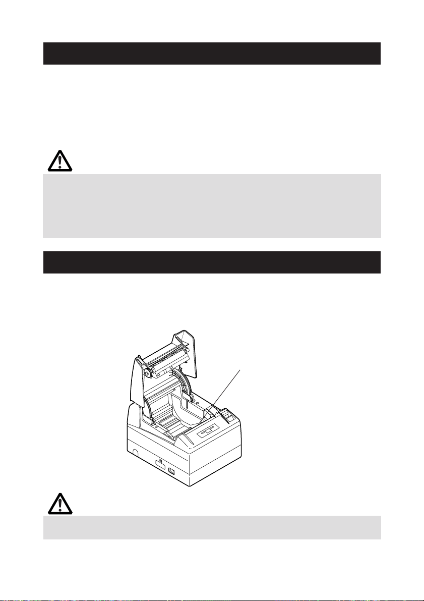
4.2 Retrait du papier coincé
1. Mettez l’imprimante hors tension.
2. Ouvrez le capot de l’imprimante.
Si la lame du coupoir reste en saillie avec le papier bloqué, ne pas forcer le
capot de l’imprimante afin de l'ouvrir. En vous référant à la Section 4.7,
ramenez la lame à sa position normale, puis ouvrez le capot.
3. Enlever le papier bourré y compris tous lambeaux de papier restants.
4. Mettez l’imprimante sous tension. Le mécanisme de découpe automatique
est initialisé et l’alarme est annulée.
ATTENTION!
■ Si la lame du coupoir reste en saillie avec le papier bloqué, NE PAS ouvrir le capot de
l’imprimante en forçant, et essayer de débrancher (OFF) et de brancher (ON)
l’alimentation de l’imprimante. Si la lame du coupoir ne peut pas être rentrée, se
référer à la Section 4.7.
■ La tête d’impression chauffe immédiatement après l’impression. Ne touchez pas
l’élément de chauffe de la tête à mains nues ou avec un objet métallique.
4.3 Nettoyage de la tête d’impression
1. Mettez l’imprimante hors tension.
2. Ouvrez le capot de l’imprimante.
3. Attendez plusieurs minutes. Essuyez les taches comme la poussière par
exemple, sur l’élément de chauffe de la tête à l’aide d’un coton-tige imbibé
d’alcool éthylique.
Tête (thermique) d’impression
ATTENTION!
La tête d’impression est chaude juste après l’impression. Ne touchez pas l’élément de
chauffe de la tête.
— 18 —
Page 48

4.4 Auto test
Insérer le papier dans l'imprimante. Avec l’interrupteur d’avance FEED pressé et maintenu
enfoncé, rétablir le courant de l’imprimante, maintenir l’interrupteur FEED enfoncé pendant
environ 1 seconde, puis libérer l’interrupteur FEED. L’imprimante démarre l’auto test.
L’imprimante imprime le nom, la version, le réglage des commutateurs DIP, le réglage du
commutateur de mémoire et les polices intégrées.
Version du programme
Interface
Condition de
communication sérielle
(uniquement pour modèle
d’interface sérielle)
Taille de tampon
Réglage de contacts
DIP (uniquement pour
modèle d’interface
sérielle)
Réglage de
commutateur
de mémoire
4.5 Hexadecimal Dump Printing
La fonction de vidage hexadécimal permet d’imprimer toutes les données envoyées en
nombres hexadécimaux. Si des problèmes tels que données manquantes, duplication
de données, etc. venaient à se produire, cette fonction permet de vérifier si l’imprimante
reçoit les données correctement.
Charger le papier dans l'imprimante et maintenir le capot de l’imprimante ouvert. Avec
l’interrupteur FEED pressé et maintenu enfoncé, rétablir le courant de l’imprimante, puis
fermer le capot de l’imprimante. Celle-ci imprime tout d’abord «HEX Dump print mode
(Vidage hexadécimal)», et elle imprime ensuite toutes les données envoyées en mode
hexadécimal .
ATTENTION!
■ S’il n’y a pas de caractère disponible correspondant aux données reçues, « . » est
imprimé à la place du caractère.
■ Pendant le vidage hexadécimal, aucune autre fonction que certaines commandes n’est
opérationnelle.
■ Si les données d'impression NE remplissent PAS une ligne, appuyer sur l’interrupteur
FEED pour imprimer la ligne.
Quand on appuie sur l’interrupteur FEED trois fois consécutivement, ou si on coupe le
courant de l’imprimante, ou l'imprimante reçoit un signal de réenclenchement de
l'interface, l'impression de vidage hexadécimal est terminée.
Exemple d’impression
HEX DUMP PRINT MODE
1B 21 00 1B 20 04 41 42 43 44 .!.. .ABCD
45 46 47 48 49 4A 4B 4C 4D 4E EFGHIJKLMN
4F 50 0D 0A 31 32 33 0D 0A OP..123..
— 19 —
Page 49

4.6 Indication des erreurs
● Fin du papier
L'état du papier épuisé est détecté en deux étapes : presque fin de papier et fin du
papier. La LED d'ERREUR s'allumera quand le papier est épuisé. Si le capot de papier
est ouvert, une fin du papier est détectée.
● Capot de papier ouvert
Pendant l'impression, ne pas ouvrir le capot de l’imprimante. Si on l’ouvre le capot
par mégarde, la LED ERREUR clignotera. Vérifier le papier, tirer le papier tout droit sur
plusieurs centimètres (ou pouces) hors de l'imprimante, puis fermer le capot de
l’imprimante. L'impression reprendra automatiquement. L'envoi d'une commande de
reprise de l’impression peut être nécessaire selon le réglage du commutateur de
mémoire.
● Surchauffe de la tête thermique
Quand vous imprimez des caractères denses ou une image foncée, la température de
la tête thermique s’élèvera. Si la température de la tête thermique excède un certain
niveau, l’imprimante cessera l’impression et attendra jusqu’à ce que la température
de la tête thermique baisse. Pendant l'attente, la LED ERREUR clignote. Quand la
température de la tête thermique est abaissée, l'impression reprendra
automatiquement.
● Verrouillage du massicot
Si la lame du mécanisme de découpe interrompt le fonctionnement dû à un bourrage
papier ou autre problème, la LED ERREUR clignotera. Éliminer la cause du problème
et appuyer sur l’interrupteur FEED. Si la lame ne se déplace pas et le capot de
l’imprimante ne peut pas être ouvert, se référer à la Section 4.7.
● Erreur de détection de Marque Noire (en mode de Marque Noire)
Quand la marque noire ne peut pas être détectée même si une certaine quantité
d'alimentation de papier est effectuée pour la détection de la marque noire, une erreur
de détection de la marque noire se produira. Si la détection de Marque Noire dépasse
une certaine durée, une condition “Pas de papier” est assumé et la même erreur que
pour “Pas de papier” est indiqué.
— 20 —
Page 50

L’état d’illumination et de clignotement de chaque erreur y compris de ce qui précède
est indiqué ci-dessous.
État
Fin de papier S’allume S’allume
Presque fin de papier S’allume S’allume
Capot de l’imprimante
ouvert
Erreur d’ouverture du S’allume
capot de l’imprimante
Blocage du massicot S’allume
Erreur surchauffe de S’allume
la tête
Erreur de surchauffe S’allume
du moteur
Erreur de contrôle S’allume
de mémoire
Erreur de basse S’allume
tension
Erreur à haute S’allume
tension
Attente d’exécution S’allume
d’une macro *2
Erreur de détection S’allume
de Marque Noire
*1: Quand l’imprimante imprime.
*2: La LED ERREUR peut clignoter même pendant l'exécution de la macro fonction.
LED ALIMENTATION LED
S’allume S’allume
*1
ERREUR Buzzer
4.7
Quand le capot de papier ne peut pas être ouvert
Si la lame du massicot reste en saillie à cause d’un bourrage papier ou de n’importe
quelle anomalie, l’ouverture du capot de papier peut être possible.
Dans ce cas, n’ouvrez pas le capot de papier en forçant. Insérez un tournevis Phillips
(Taille #1) dans l’orifice de déblocage du massicot et tournez-le dans la direction de la
flèche (dans le sens des aiguilles d’une montre).
Quand vous constatez que les deux extrémités de la lame ont atteint la position la plus
basse, arrêtez de tourner le tournevis. Ouvrez le capot et suivez la méthode pour enlever
le bourrage ou une autre cause de problème.
Tournevis Phillips
Orifice de déblocage du massicot
— 21 —
Page 51

5. DIVERS
5.1 Vues et dimensions externes
147
(Unité: mm)
177
213
5.2 Papier d’impression
Utiliser le papier d’impression indiqué dans le tableau suivant ou le papier avec une
qualité équivalente.
Type de papier Nom du produit
Rouleau de papier F230AA, P220AG, HP220A, HP220AB-1, P220AB, P220AE-1,
thermique recommandé
Largeur de papier
Surface d’impression maximum
44
Surface d’impression
d
D
φ 102 ou moins
PB670 (Rouge/Noir ), PB770 (Bleu /Noir) from Mitsubishi Paper
TF50KS-E2D from Nippon Paper
PD150R, PD160R from Ohji Paper
112
0
−1
104
65~150
Largeur de papier
Surface d’impression maximum
Épaisseur de papier (µm) 65-75 75-150
Diamètre intérieur du noyau d
Diamètre extérieur du noyau D
82.5
0
−1
82.5
Surface d’impression maximum
44
(mm) φ12 φ25.4
(mm) φ18 φ32
Largeur de papier
80
(Unité: mm)
0
−1
72
ATTENTION!
NE PAS utiliser le type de rouleau de papier suivant.
■ Papier avec des plis.
■ Papier avec les coins pliés.
■ Papier collé ou collé au noyau.
■ Rouleau de papier enroulé vers l’intérieur (côté d'impression interne).
— 22 —
Page 52

5.3
Réglage manuel du commutateur de mémoire
Les commutateurs de mémoire peuvent être placés manuellement ou par commande.
Pour le réglage manuel, se référer à la prochaine page.
La fonction de chaque commutateur de mémoire est indiquée dans le tableau suivant.
(Les caractères blanc-sur-noir représentent ceux de réglage d’usine).
No. commutateur
Memory SW1-1 Power ON Info Valid Not send
SW1-2 Buffer Size 4k bytes 45 bytes
SW1-3 Busy Condition Full/Err Full
SW1-4 Receive Error Print "?" No Print
SW1-5 CR mode Ignored LF
SW1-6 Reserved Fixed −
SW1-7 DSR Signal Invalid Valid
SW1-8 Init Signal Invalid Valid
Memory SW2-1 Reserved − Fixed
SW2-2 Auto Cutter Invalid Valid
SW2-3 Spool Print Invalid Valid
SW2-4 Full Col Print LineFeed WaitData
SW2-5 Resume aft PE Next Top
SW2-6 Reserved Fixed −
SW2-7 Reserved Fixed −
SW2-8 PNE Sensor Valid Invalid
Memory SW3-1 Resum Cttr Err Valid Invalid
SW3-2 Reserved Fixed −
SW3-3 Parallel 31 Pin Valid Invalid
SW3-4 Reserved Fixed −
SW3-5 Reserved Fixed −
SW3-6 Reserved Fixed −
SW3-7
SW3-8
Memory SW4-1 *3 P. Length Set Auto Measure Command
SW4-2 *3 Power on TOF Invalid Valid
SW4-3 Feed&Cut at TOF Invalid Valid
SW4-4 *3 Paper Select *1 Thermal Roll BM.P / Lbl.P
SW4-5 Position detect *2 Black Mark Label
SW4-6 Reserved Fixed −
SW4-7 Reserved Fixed −
SW4-8 Prtial Only Invalid Valid
Memory SW5-1 Buzzer Valid Invalid
SW5-2 Line Pitch 360 406
SW5-3 USB Mode Virtual COM Printer Class
SW5-4 Reserved Fixed −
SW5-5 Power OFF Info Invalid Valid
SW5-6 Reserved Fixed −
SW5-7 Reserved Fixed −
SW5-8 Reserved Fixed −
Notes:
*1: Le réglage à l’usine de «Sélection papier» [Paper Select] sera différent, selon la classification du modèle.
*2: Dans le cas du choix du rouleau thermique avec le SW4-4, le SW4-5 ne sera pas disponible. Le SW4-5
sera réglé à l’état de «Marque Noire» [Black Mark] pour l'imprimante de version Marque Noire.
*3: Les modèles SW4-1, 4-2, 4-4, et 4-5 sont disponibles pour l'imprimante de version Marque Noire
seulement.
Réglage 0 (OFF) 1 (ON)
CBM1000 Mode
Resum Open Err
Invalid Valid
Close Command
— 23 —
Page 53

No. commutateur
Memory SW7-1 Baud Rate 9600 bps 1200 bps, 2400 bps, 4800 bps, 9600 bps,
SW7-2 Data Length 8Bits 7Bits, 8Bits
SW7-3 Stop Bit 1Bit 1Bit, 2Bits
SW7-4 Parity NONE NONE, EVEN, ODD
SW7-5 Flow Control DTR/DSR DTR/DSR, XON/XOFF
SW7-6 DMA Control Valid Valid, Invalid
SW7-7
Memory SW8-1 Print Width 832dots
SW8-2 Paper Type 1 Color Normal 1 Color Normal, 2 Color Normal
Memory SW9-1 Code Page PC437 PC437/Katakana/PC850,858/PC860/PC863/
Memory SW9-2 Int'Char Set USA USA, France, Germany, England, Denmark,
Memory SW9-3* Kanji OFF ON, OFF
SW9-4* JIS/Shift JIS JIS JIS, Shift JIS
Memory SW10-1 Print Density 100% 70%, 75%, 80%, 85%, 90%, 95%, 100%, 105%,
SW10-2 Print Speed Level 9 Level 1, Level 2, Level 3, Level 4, Level 5,
SW10-3 ACK Timing Before Busy Before Busy, Same Period, After Busy
SW10-4 NV User 192K bytes 1K bytes, 64K bytes, 128K bytes, 192K bytes
SW10-5 NV Graphic 384K bytes 0 byte, 64K bytes, 128K bytes, 192K bytes,
* Les commutateurs de mémoire 9-3 et 9-4 de cette imprimante ne peuvent pas s’utiliser.
Réglage
VCom Protocol
Réglage par défaut
19200 bps, 38400 bps, 57600 bps, 115200 bps
PC Setting PC Setting, DTR/DSR, XON/XOFF
832dots(69 col.), 720dots(60col.), 660dots(55col),
576dots(48col.), 512dots(42col)
PC865/PC852/PC866/PC857/WPC1252/PC864/
Thai Code 18
Sweden, Italy, Spain, Japan, Norway,
Denmark 2, Spain 2, Latin America, Korea
Croatia, China
110%, 115%, 120%, 125%, 130%, 135%, 140%
Level 6, Level 7, Level 8, Level 9
256K bytes, 320K bytes, 384K bytes
Valeurs de réglage
Réglage manuel du commutateur de mémoire (“Memory SW”)
Le commutateur de mémoire peut être sélectionné, changé, ou écrit par la combinaison
de trois actions: en appuyant sur l’interrupteur FEED, en pressant et en maintenant
enfoncé l’interrupteur FEED, et en ouvrant ou fermant le capot de l’imprimante.
1. Passage en mode de réglage du commutateur de mémoire
Mettre le papier dans l'imprimante et maintenir le capot de l’imprimante ouvert.
Avec l’interrupteur FEED pressé et maintenu enfoncé, activer l’alimentation de
l’imprimante, puis presser l’interrupteur FEED deux fois. Fermez le capot. Si les
réglages actuels du commutateur de mémoire, etc. sont imprimés, l’imprimante
est maintenant en mode de réglage du commutateur de mémoire.
Memory SW (1) 00000000
(Aucune indication pour 0/1 avec commutateur de mémoire SW7 à SW10)
— 24 —
0: État OFF (arrêt)
1: État ON (marche)
Page 54

2.
Sélection du commutateur de mémoire (MODE DE SÉLECTION DU COMMUTATEUR DE MÉMOIRE)
Quand l’interrupteur FEED est appuyé pour une durée courte (*1), l'impression se
produit dans la séquence de “Memory SW1” → “Memory SW2” → “Memory SW3”
→ ......“Memory SW10” → “Save To Memory” → “Memory SW1” →...... à plusieurs
reprises. Quand le commutateur de mémoire que l’on veut changer est atteint,
presser et maintenir enfoncé l’interrupteur FEED (pendant plus de 2 secondes).
3. Selecting each switch item
Un nombre de 3-8 items sont fournis pour régler avec chaque commutateur. En
pressant et en maintenant enfoncé l’interrupteur FEED pour une longue durée (*2),
l'imprimante passera au prochain item et imprime le réglage courant de l'item.
Presser et maintenir enfoncé jusqu'à l'item que l’on veut changer soit atteint.
Power ON notify setting (Valid )
(Avec le commutateur de mémoire SW7 à SW10, la DEL ERREUR s’illumine seulement avec le réglage faite à la fabrique).
État OFF: LED ERREUR OFF
État ON: LED ERREUR ON
4. Changement du réglage
Quand l’item que l’on veut changer est imprimé, presser l’interrupteur FEED pour
une courte durée (*1). La valeur de réglage changée est alors imprimée. (Quand le
changement de la valeur de réglage est répété, la valeur de réglage d’origine est
récupérée).En pressant l’interrupteur FEED pour une longue durée (*2), la valeur
de réglage est acceptée et l'imprimante passera alors au prochain item de réglage.
5.
Retour au MODE DE SÉLECTION Du COMMUTATEUR DE MÉMOIRE (Item 2 ci-dessus)
Quand le réglage du contenu désiré est complété, ouvrez le capot de papier, puis
fermez-le. Ceci permettra à l’imprimante d’imprimer le réglage du commutateur
de mémoire changé.
6. Pour sauvegarder le réglage et quitter le mode de réglage du commutateur de
mémoire
Presser l’interrupteur FEED pour une courte durée (*1) pour se déplacer à “Save To
Memory”. Puis presser et maintenir enfoncé l’interrupteur FEED. L’imprimante
imprime le contenu du nouveau réglage et quittera le mode de réglage du
commutateur de mémoire pour retourner à l’état normal d’attente.
*À moins que la sauvegarde du réglage soit exécuté, le réglage changé ne peut
pas être validé.
7. Initialisation du commutateur de mémoire
Quand vous voulez remettre le commutateur de mémoire à l’état initial, passez à la
procédure "Save To Memory" mentionnée ci-dessus. Dans ce cas, ouvrir le capot
de l’imprimante, puis presser et maintenir enfoncé l’interrupteur FEED jusqu'à ce
que le buzzer sonne. Ceci permettra à l’imprimante de retourner à l’état initial.
*Toutes les positions des commutateurs de mémoire sont retournées aux valeurs
réglées à l’usine.
* 1 : Presser pendant moins de 2 secondes * 2 : Presser pendant plus de 2 secondes
— 25 —
Page 55

DEUTSCH
Page 56

ALLGEMEINE VORSICHTSMASSNAHMEN
● Lesen Sie sich das vorliegende Benutzerhandbuch sorgfältig durch, bevor Sie das Gerät
verwenden. Verwahren Sie es danach an einem sicheren, leicht zugänglichen Ort, um bei
Bedarf darauf zurückgreifen zu können.
● Der Hersteller behält sich vor, die hierin enthaltenen Informationen ohne vorherige
Ankündigung zu ändern.
● Jegliche Reproduktion und Weitergabe von Teilen oder der Gesamtheit des Dokuments ohne
vorherige Genehmigung von Citizen Systems ist untersagt.
● Beachten Sie, dass Citizen Systems jede Haftung für Folgen aus dem Betrieb des Geräts
unabhängig von im vorliegenden Handbuch enthaltenen Auslassungen, Fehlern oder
Druckfehlern ausschließt.
● Beachten Sie, dass Citizen Systems keine Haftung für jegliche Störungen übernimmt, die
infolge der Verwendung von in diesem Handbuch nicht autorisierten Zubehörteilen oder
Verbrauchsmaterialien entstehen.
● Mit Ausnahme der in diesem Handbuch genannten Fälle darf das Gerät nicht selbst gewartet,
zerlegt oder repariert werden.
● Beachten Sie, dass Citizen Systems keine Haftung für jegliche Störungen übernimmt, die
infolge von unsachgemäßer Verwendung oder nicht geeigneter Betriebsumgebungen
auftreten, auch wenn in diesem Handbuch nicht darauf hingewiesen wird.
● Daten sind im Allgemeinen für temporären Gebrauch und werden nicht für längere Zeit oder
permanent gespeichert . Beachten Sie, dass Citizen Systems keine Haftung für jegliche
Schäden oder entgangene Verluste übernimmt, die aus Datenverlusten infolge von
unvorgesehenen Ereignissen, Reparaturen, Tests oder sonstigem entstehen.
● Wenn Ihnen fehlende Informationen, Fehler oder Unklarheiten auffallen, wenden Sie sich an
Ihren Citizen Systems-Händler.
● Wenn Ihnen fehlende Seiten oder sonstige Mängel auffallen, wenden Sie sich zwecks Ersatz
an Ihren Citizen Systems-Händler.
Authorisierte Repräsentanz in Europa: Citizen Systems Europe GmbH
Maschinenlärminformations-Verordnung – 3.GPSGV, 06.01.2004:
Der höchste Schalldruckpegel beträgt 60 dB(A) oder weniger gemäß EN ISO 7779
Mettinger Strasse 11
D-73728, Esslingen
Germany
INHALTSVERZEICHNIS
1. ALLGEMEINE ÜBERSICHT .........................................................7
2. ERLÄUTERUNG DER DRUCKERKOMPONENTEN ................. 10
3. VORBEREITUNG ....................................................................... 12
4. WARTUNG UND FEHLERBEHEBUNG ..................................... 17
5. SONSTIGES .............................................................................. 22
CITIZEN is a registered trade mark of CITIZEN WATCH CO., LTD., Japan
CITIZEN es una marca registrada de CITIZEN WATCH CO., LTD., Japón
Company names and product names in this manual are trademarks or
registered trademarks of relevant companies.
Copyright c 2006 by CITIZEN SYSTEMS JAPAN CO., LTD.
— 1 —
Page 57

SICHERHEITSMASSNAHMEN ...
Lesen Sie sich vor der erstmaligen Verwendung des Produkts die
SICHERHEITSMASSNAHMEN sorgfältig durch.
Falsche Handhabung kann zu Unfällen führen (Brände, elektrische Schläge oder
Verletzungen). Um Verletzungen von Benutzern und Dritten sowie materielle Schäden
zu vermeiden, werden im Handbuch spezielle Warnsymbole verwendet, die auf
wichtige Informationen hinweisen.
● Bewahren Sie das Handbuch danach an einem sicheren, leicht zugänglichen Ort auf,
um bei Bedarf darauf zurückgreifen zu können.
● Einige der im Handbuch enthaltenen Beschreibungen sind möglicherweise für Ihr
Druckermodell nicht von Bedeutung.
Nachstehend wird der Grad der Gefahren und Schäden beschrieben, die bei
unsachgemäßem Betrieb des Druckers oder Nichtbeachtung der durch die
Warnsymbole gekennzeichneten Hinweise entstehen können.
DIE SIE STRIKT EINHALTEN MÜSSEN
WARNHINWEIS
Bei Nichtbeachtung derartig gekennzeichneter Informationen kann es zu schweren
oder tödlichen Verletzungen kommen.
VORSICHT
Bei Nichtbeachtung derartig gekennzeichneter Informationen kann es zu Verletzungen
oder materiellen Schäden kommen.
Dieses Symbol wird verwendet, um Sie auf wichtige Informationen
aufmerksam zu machen.
Dieses Symbol weist auf Gefahren durch elektrische Schläge und mögliche
Schäden durch statische Elektrizität hin.
Dieses Symbol weist darauf hin, dass der Netzstecker des Geräts zu ziehen ist.
Dieses Symbol wird verwendet, um nützliche Informationen, wie Verfahren
oder Anweisungen zur Benutzung hervorzuheben.
Dieses Symbol dient zur Warnung vor unzulässigen Eingriffen.
— 2 —
Page 58

WARNHINWEIS
■ Verwenden und lagern Sie das Gerät nicht an Orten, an denen es folgenden
Einflüssen ausgesetzt ist:
* Flammen oder hohe Luftfeuchtigkeit.
* Direkte Sonneneinstrahlung.
* Heißluftströme oder Abwärme von Heizgeräten.
* Salzige Luft oder korrosive Gase.
* Unzureichende Belüftung.
* Chemische Reaktionen in Laboren.
* Ölnebel, Stahlpartikel oder Staub.
* Statische Elektrizität oder starke Magnetfelder.
• Die Nichtbeachtung dieser Warnhinweise kann zu Ausfällen des Druckers,
Überhitzung sowie Rauch, Feuer oder elektrischen Schlägen führen.
■ Keine Gegenstände in den Drucker einführen. Keine Flüssigkeiten in den Drucker
spritzen. Keine Gegenstände auf dem Drucker ablegen.
■ Keine Metallgegenstände wie Büroklammern, Heftklammern oder Schrauben in
den Drucker fallen lassen.
■ Keine Blumenvasen, Töpfe oder Tassen mit Flüssigkeiten auf dem Drucker abstellen.
■ Darauf achten, dass keine Getränke oder sonstigen Flüssigkeiten in den Drucker
geraten.
■ Keine Insektenvertilgungsmittel oder sonstige Chemikalien auf den Drucker
sprühen.
•Wenn Fremdgegenstände aus Metall in den Drucker geraten, kann es zum Ausfall
des Druckers, Bränden oder elektrischen Schäden kommen. In derartigen Fällen
ist der Drucker sofort abzuschalten und vom Netz zu trennen. Wenden Sie sich an
Ihren örtlichen Citizen Systems-Händler.
Gehen Sie stets sachgemäß mit dem Drucker um:
■ Den Drucker keinen Stößen oder Schlägen aussetzen (z.B. Tritte, Schütteln, Stöße
mit harten Gegenständen).
■ Den Drucker nicht demontieren oder sonstig modifizieren.
• Bei nicht sachgemäßem Umgang kann es zum Ausfall des Druckers, Überhitzung
sowie Brand- und Rauchentwicklung oder elektrischen Schlägen kommen.
■ Platzieren, verwenden und lagern Sie den Drucker außerhalb der Reichweite von
Kindern.
•Von elektrischen Geräten können bei unsachgemäßer Handhabung oder
Verwendung Unfall- und Verletzungsrisiken ausgehen.
• Achten Sie darauf, dass sich das Netzkabel und die Signalkabel außerhalb der
Reichweite von Kindern befinden. Der Drucker ist so aufzustellen, dass Kinder keinen
Zugang zum Geräteinnern erlangen können.
• Die Kunststoffhülle, in der sich der Drucker bei der Lieferung befindet, ist
ordnungsgemäß zu entsorgen oder außerhalb der Reichweite von Kindern
aufzubewahren. Wenn die Hülle über den Kopf gezogen wird, besteht
Erstickungsgefahr.
— 3 —
Page 59

WARNHINWEIS
Beachten Sie die nachstehenden Vorsichtsmaßnahmen zur Stromversorgung und
zum Netzkabel:
■ Den Netzstecker nicht mit feuchten Händen anschließen oder ziehen.
■ Betreiben Sie den Drucker ausschließlich mit der angegebenen Netzspannung
und -frequenz.
■ Stellen Sie sicher, dass die Netzsteckdose, an die der Drucker angeschlossen ist,
eine ausreichende Belastbarkeit aufweist.
■ Verwenden Sie zur Stromversorgung keine Anschlussleisten oder
Mehrfachsteckdosen, an die gleichzeitig auch andere Geräte angeschlossen sind
■ Säubern Sie den Netzstecker vor dem Anschließen an die Netzsteckdose von
Staub und anderen Ablagerungen.
■ Verwenden Sie keine verformten oder beschädigten Netzkabel.
■ Bewegen Sie den Drucker nicht in eingeschaltetem Zustand.
• Bei nicht sachgemäßem Umgang kann es zum Ausfall des Druckers, Brand- und
Rauchentwicklung oder elektrischen Schlägen kommen.
• Bei Überlastung kann sich das Netzkabel überhitzen und in Brand geraten oder
der Schutzschalter ausgelöst werden.
■ Stellen Sie keine Gegenstände auf das Netzkabel. Stellen Sie den Drucker so auf,
dass nicht auf das Netzkabel getreten wird.
■ Achten Sie darauf, dass das Netzkabel beim Benutzen und Transportieren des
Druckers nicht verbogen oder verdreht und keinem Zug ausgesetzt wird.
■ Versuchen Sie nicht, das Netzkabel zu modifizieren.
■ Verlegen Sie das Netzkabel nicht in der Nähe von Heizgeräten.
• Die Nichtbeachtung dieser Vorsichtsmaßnahmen kann Drahtbrüche oder
Beschädigungen der Isolierung zur Folge haben, wodurch die Gefahr von
Kriechströmen, elektrischen Schlägenoder Beschädigungen des Druckers
besteht. Wenn das Netzkabel beschädigt wurde, wenden Sie sich bitte an Ihren
Citizen-Systems-Händler.
■ Stellen Sie sicher, dass der Zugang zur belegten Steckdose nicht durch
abgestellte Gegenstände behindert wird.
■ Versorgen Sie den Drucker über eine günstig platzierte Steckdose, die im Notfall
problemlos zugänglich ist.
• In Notfällen wird der Drucker möglicherweise nicht sofort abgeschaltet.
■ Stecken Sie den Netzstecker ordnungsgemäß in die Steckdose.
■ Ziehen Sie bei längerer Nichtbenutzung des Geräts den Netzstecker aus der
Steckdose.
■ Nach dem Abschalten des Druckers und des daran angeschlossenen Geräts beim
Trennen des Netzkabels oder der Signalleitung den Stecker und den Anschluss
greifen. Ziehen Sie das Netzkabel, nachdem Sie den Drucker ausgeschaltet
haben, in dem Sie das Kabel am Stecker festhalten.
— 4 —
Page 60

VORSICHT
Unter folgenden Bedingungen darf der Drucker nicht verwendet werden:
■ An Orten mit Vibrationen oder bei instabiler Aufstellung.
■ Bei unebener Aufstellung.
• Andernfalls könnte der Drucker herunterfallen und Verletzungen verursachen.
• Mögliche Beeinträchtigung der Druckqualität.
■ Wenn die Belüftungslöcher des Druckers durch Wände oder andere Geräte
blockiert werden.
■ wenn sich Gegenstände auf dem Drucker befinden, oder
■ wenn der Drucker durch Kleidung oder Tücher zugedeckt ist.
• Achten Sie darauf, dass es im Inneren des Geräts nicht zu Überhitzungen
kommt, infolge derer es zu Bränden oder Verformungen des Gehäuses kommen
kann.
■ Stellen Sie den Drucker nicht in der Nähe von Rundfunk- oder
Fernsehempfängern auf und versorgen Sie ihn nicht zusammen mit derartigen
Geräten aus derselben Steckdose.
■ Vermeiden Sie es, den Drucker über nicht abgeschirmte Kabel oder Leitungen zu
betreiben. (Verwenden Sie für die Signalleitungen abgeschirmte Kabel oder
verdrillte Doppelkabel mit Ferritkernen oder andere Abschirmverfahren.)
■ Benutzen Sie den Drucker nicht zusammen mit Geräten, die starke Störstrahlung
abgeben.
• Der Drucker kann den Radio- oder Fernsehempfang in der Umgebung
beeinträchtigen. Es besteht auch die Möglichkeit, dass benachbarte elektrische
Geräte den Drucker beeinflussen und dadurch Datenfehler oder
Funktionsstörungen auftreten.
■ Bei senkrechter oder seitlich gekippter Aufstellung.
• Andernfalls besteht die Gefahr von Fehlfunktionen, Ausfällen oder Stromschlag.
■ Erden Sie den Drucker vor der Benutzung in geeigneter Weise.
• Bei Auftreten von Kriechströmen besteht Stromschlaggefahr.
■ Schließen Sie den Erdungsleiter des Druckers nicht an folgende Gegenstände an:
* Gasleitungen
• Andernfalls besteht die Gefahr von Gasexplosionen.
* Erdungen von Telefonleitungen
* Blitzableiter
• Andernfalls besteht bei Blitzeinschlägen durch Spannungsspitzen Brandoder Stromschlaggefahr.
* Wasserleitungen
• Wasserleitungen aus Kunststoff sind zur Erdung nicht geeignet (sofern keine
Zustimmung der zuständigen Wasserwerke vorliegt).
■ Vor Anschließen oder Trennen des Druckererdungsleiters stets den Netzstecker
des Geräts ziehen.
Das Vorsicht-Symbol befindet sich an der in der
nebenstehenden Zeichnung gezeigten Position. Lesen Sie
sich die Vorsichtsmaßnahmen sorgfältig durch, bevor Sie
den Drucker in Betrieb nehmen.
DIESE ZEICHEN WEISEN AUF VERLETZUNGSGEFAHREN
DURCH DIE „HOHE TEMPERATUR" DES DRUCKKOPFES UND
DIE „SÄGEZAHNKANTE" DER MANUELLEN
SCHNITTVORRICHTUNG HIN.
— 5 —
Page 61

VORSICHT
■ Transportieren Sie diesen Drucker nicht mit eingesetzter Papierrolle.
• Sonst besteht die Gefahr von Druckerversagen oder Schäden.
Beachten Sie die folgenden Hinweise, um Fehlfunktionen zu vermeiden.
■ Den Drucker nicht mit nicht ordnungsgemäß eingesetzter Papierrolle verwenden.
■ Kein Papier verwenden, dass nicht den Spezifikationen entspricht.
• Mögliche Beeinträchtigung der Druckqualität.
■ Kein eingerissenes oder mit Klebestreifen zusammengefügtes Papier verwenden.
■ Nicht mit der Hand gewaltsam am bereits eingesetzten Papier ziehen.
■ Das Papier nicht gewaltsam in den Drucker pressen.
• Papierstau möglich. Informationen zur Fehlerbehebung finden Sie im Abschnitt
„Beseitigen von Papierstaus“ in diesem Handbuch.
■ Die Tasten im Bedienungsfeld nicht mit scharfen oder spitzen Objekten betätigen.
■
Stellen Sie sicher, dass die Kabel ordnungsgemäß mit den Anschlüssen verbunden sind.
•
Bei Querschaltung kann es zu Beschädigungen der Druckerelektronik oder der Hardware
des Host-Systems kommen.
■
Schließen Sie den Drucker mit Geldlade-Kickout-Funktion ausschließlich an Geräte an, die
ein Solenoid mit für die Geldlade-Kickout-Buchse geeigneten technischen Daten besitzen.
•
Bei Nichtbeachtung dieser Vorsichtsmaßnahme können Funktionsfehler und Störungen
auftreten.
Beachten Sie die folgenden Hinweise, um bei Ausfällen des Geräts Verletzungen und
Beschädigungen zu vermeiden.
■ Die Druckoberfläche des Thermokopfes nicht berühren.
■ Berühren Sie während des Druckerbetriebs keine beweglichen Teile im Inneren des
Druckers (z.B. Papierschneider, Zahnräder und aktivierte elektrische Bauteile).
■ Versuchen Sie nicht, den Drucker bei etwaigen Problemen selbst zu reparieren.
Verständigen Sie den Citizen Systems-Kundendienst.
■ Achten Sie darauf, sich nicht an der Druckerabdeckung die Hand oder Finger
einzuklemmen.
■ Achten Sie darauf, sich nicht an scharfen Kanten im Drucker zu verletzen und daran
keine anderen Gegenstände zu beschädigen.
• Hier besteht Stromschlag-, Verbrennungs- und Verletzungsgefahr.
Falls sich beim Drucken Rauch entwickelt oder der Drucker ungewöhnliche Gerüche oder Geräusche erzeugt,
den Druckvorgang sofort abbrechen und den Netzstecker aus der Steckdose ziehen.
TÄGLICHE WARTUNG
Beachten Sie bei der täglichen Wartung die folgenden Vorsichtsmaßnahmen:
■
Vor dem Reinigen ist der Drucker stets auszuschalten und der Netzstecker zu ziehen.
■
Zum Abwischen des Oberfläche des Druckergehäuses ein weiches, trockenes Tuch
verwenden.
■
Hartnäckige Verschmutzungen mit einem weichen Tuch entfernen, das leicht mit Wasser befeuchtet wurde.
■
Verwenden Sie keine flüchtigen organischen Lösungsmittel wie Alkohol, Terpentin oder
Benzol. Verwenden Sie keine chemisch behandelten Reinigungstücher
■ Zum Entfernen von Papierstaub einen weichen Pinsel verwenden.
VORSICHT
•
Unmittelbar nach dem Drucken ist der Thermokopf sehr heiß, sodass Verbrennungsgefahr
besteht. Warten Sie vor Wartungsarbeiten ab, dass der Thermokopf abgekühlt ist.
— 6 —
Page 62

1. ALLGEMEINE ÜBERSICHT
Die Modelle CT-S4000/CT-S4000DC sind kompakte Thermo-Zeilendrucker, die sich für
verschiedene Terminallösungen eignen, darunter Daten-, POS- und Küchenterminals.
Aufgrund ihrer umfassenden Funktionen können die Geräte mit einer Vielzahl von
Anwendungen kombiniert werden.
1.1 Funktionen
● Vielseitige Rollenkapazität mit der Möglichkeit, 80 mm, 82.5 mm und 112 mm breite
Papierrollen zu verwenden.
● Für Papierrollen mit maximal 102 mm Durchmesser.
● Drop-in-Ladeautomatik für Papierrollen zur Vereinfachung der Papierzufuhr und der
Reinigung des Thermokopfes.
● Hochgeschwindigkeitsdruck (150 mm/s).
● Ausgestattet mit USB-Schnittstelle als Standard sowie Wahl zwischen serieller oder
paralleler Schnittstelle.
● Austauschbare Schnittstellenkarte.
● Hochgeschwindigkeits-Parallelschnittstelle (Modell mit Parallelschnittstelle)
● Eingebaute Geldladen-Schnittstelle.
● Automatischer Papierschneider als Standardausrüstung.
● Anwenderanpassung wie Speicherschalter-Einstellung ist möglich.
● Page mode.
● Erfassung benutzerdefinierter Zeichen und Logos im Flash-Speicher.
● Barcode-Druck
● 2-Farb-Druck ist unterstützt (wenn geeignetes Papier verwendet wird).
● Fehleranzeige mit LED oder Signalton ist verfügbar.
● Wandanbringung durch Verwendung des optionalen Wandmontage-Kits möglich.
— 7 —
Page 63

1.2 Auspacken
Ver gewissern Sie sich beim Auspacken des Druckers, dass alle nachstehend aufgeführten
Teile vorhanden sind:
● Drucker: 1
● Netzkabel: 1 (nur für CT-S4000)
● Benutzerhandbuch (das vorliegende Handbuch): 1
● Probe-Papierrolle: 1 Rolle
● Trennvorrichtung: 1
● Schraube: 1
Benutzerhandbuch
(das vorliegende
Handbuch)
CT-S4000
Probe-Papierrolle
Netzkabel
Trennvorrichtung Schraube
1.3 Modellklassifizierung
Die Modellbezeichnungen der Druckermodelle sind nach folgendem Schema aufgebaut:
CT - S4000 RS E - BK -
Stromversorgung
Keine Markierung:
Ausführung mit
Netzteil
(integriertes Netzteil)
DC: Ausführung mit
Gleichstromversorgung
Schnittstelle
PA: IEEE1284 u. USB
RS: RS-232C u. USB
UB: nur USB (Option)
Label / Black-Mark
Keine Markierung: Standard
L: Label Version
M: Black-Mark Version
Gerätegehäusefarbe
WH:Coolwhite
BK: Schwarz
Zeichensatz, Netzkabel,
E: Europa
U: USA
— 8 —
Page 64

1.4 Grundlegende technische Daten
Gegenstand Technische Daten
Modell CT-S4000 PA/RS/UB, CT-S4000DC PA/RS/UB
Druckverfahren Thermo-Zeilenpunktdruck
Druckbreite *1 112 mm/832 Punkte, 82.5 mm/660 Punkte, 80 mm/576 Punkte
Punktdichte 8 × 8 Punkte/mm (203 dpi) horizontal u. vertikal
Druckgeschwindigkeit 150 mm/s (max., Druckdichte 100%), 1200 Punktzeilen/s
Anzahl Druckspalten
*2
Schrift
Papierbreite
Schrift A 69 55 48 12 × 24
Schrift B 92 73 64 9 × 24
Schrift C 104 82 72 8 × 16
Zeichengröße *3 Schrift A: 1.50 × 3.00 mm
Schrift B: 1.13 × 3.00 mm
Schrift C: 1.00 × 2.00 mm
Zeichentyp Alphanumerische Zeichen, internationale Zeichen, Codeseiten PC437/
850/852/857/858/860/863/864/865/866/WPC1252/Katakana/Thai-Code 18
Benutzerspeicher 384 KB (Zum Speichern von benutzerdefinierten Zeichen und Logos)
Strichcode-Typen UPC-A/E, JAN (EAN) 13/8-Spalten, ITF, CODE 39, CODE 128,
CODABAR, CODE 93
Zeilenabstand *4 4,23 mm (1/6 Zoll)
Papierrolle Thermopapierrolle: 112 mm/82.5 mm/80 mm × Maximum φ102 mm
Papierstärke: 65-150 µm
Schnittstellen
Geldlade-Kickout-Buchse
Eingangspufferspeicher
Seriell, (RS-232C-kompatibel), Parallel (IEEE 1284-kompatibel), USB
2 Fächer werden unterstützt
4 KByte/45 Byte (wählbar) bei serieller oder paralleler Schnittstelle,
16 KByte bei USB-Schnittstelle
Versorgungsspannung 100 bis 240 V Wechselstrom, 50/60 Hz, 130 VA / 24 V Gleichstrom, 2,0 A
Leistungsaufnahme Ca. 70 W (im Normaldruckbetrieb)
Gewicht CT-S4000:Ca. 2.3 kg, CT-S4000DC:Ca. 2.0 kg
Äußere Abmessungen 177 (W) × 213 (D) × 147 (H) mm
Betriebstemperatur und
5 bis 45 °C, 10 bis 90 % relative Luftfeuchtigkeit(kondensationsfrei)
Feuchtigkeit
Lagertemperatur und –20 bis 60°C, 10 bis 90 % relative Luftfeuchtigkeit(kondensationsfrei)
Feuchtigkeit
Zuverlässigkeit
Lebensdauer Druckkopf: 100 km, 1 × 10⁸ Impulse
(normale Temperatur/ Luftfeuchtigkeit, empfohlenes Papier)
Lebensdauer autom. Papierschneider: 1.000.000 Schneidvorgänge
(normale Temperatur/Luftfeuchtigkeit, empfohlenes Papier)
Sicherheitsstandard UL, C-UL, FCC Class A, TÜV-GS, CE Marking
Hinweise:
*1: Wenn die Papierbreite 112, 82.5, 80 mm ist
*2: Die Anzahl ausdruckbarer Spalten wird per Speicher-Switch eingestellt.
Die Anzahl von Spalten in dieser Tabelle bezieht sich auf ein typisches Modell. Die Anzahl der
druckbaren Spalten ist je nach Druckerspezifikationen unterschiedlich.
*3: Da jede Zeichengröße den Bereich innerhalb der Zeichenschriftart enthält, sieht das tatsächliche
Zeichen kleiner aus.
*4: Der Zeilenabstand ist mit Befehl oder Speicher-Switch wählbar. Bei eingeschaltetem Drucker
geschieht die Wahl mit dem Speicher-Switch.
Anzahl Druckspalten
(Spalten)
112mm 82.5mm 80mm
0
−1
0
0
−1
−1
Punktkonfiguration
(Dot)
— 9 —
Page 65

2.
ERLÄUTERUNG DER DRUCKERKOMPONENTEN
2.1 Ansicht des Druckers
Druckerabdeckung
● Druckerabdeckung
Unter dieser Abdeckung ist
das Papier eingelegt.
● Abdeckung-Öffnen-Knopf
Ziehen Sie den AbdeckungÖffnen-Knopf nach vorne,
um Papier nachzufüllen
oder auszutauschen.
● Netzschalter
Dieser Schalter dient zum An- und Ausschalten des Geräts.
● Schiebe-Öffnung
Die am Drucker angeschlossenen Kabel können durch diese Schiebe-Öffnung geführt
werden.(Vor der Verwendung drücken Sie die kleine Plastikbarriere auf der Abdeckung,
bis sie bricht.)
Bedienungsfeld
BETRIEBS-LED
● Betriebs-LED (POWER)
Beleuchtet, wenn der Drucker eingeschaltet ist. Wenn der Drucker ausgeschaltet wird,
geht die Lampe aus. Je nach Betriebsmodus oder bei Problemen beginnt die LED zu
blinken.
Schiebe-
Öffnung
Netzschalter
(Vorderansicht) (Rückansicht)
Vorschubtaste
(FEED)
Abdeckung-Öffnen-Knopf
Schiebe-
Öffnung
Bedienungsfeld
Vorschubtaste (FEED)
Rückwärtiger
Anschluss
● Fehler-LED (ERROR)
Beleuchtet oder blinkt, wenn kein Papier vorhanden ist oder ein Fehler aufgetreten ist.
Das Blinkintervall stellt den Fehlertyp dar.
● Vorschubtaste (FEED)
Wenn Sie diese Taste betätigen, wird das Papier um eine Zeile vorgeschoben. Je länger
die Taste gedrückt wird, desto mehr Papier wird vorgeschoben.
Wenn Sie diese Taste betätigen, wird das Papier im Black-Mark-Modus bis zur nächsten
Black-Mark-Position vorgeschoben.
Siehe5.3 Manuelle Einstellung von Speicher-Switches
Bei Blockierung des automatischen Papierschneiders können Sie nach Beseitigung
der Fehlerursache die Vorschubtaste (FEED) betätigen, um die Fehlerursache zu
beheben.
— 10 —
Siehe 4.6 Fehleranzeige
Page 66

Rückwärtige Anschlüsse
Stromanschluss
(Ausführung mit
Gleichstromversorgung)
Schnittstellenanschluss
(seriell, parallel, usw.)
Netzeingang
(Ausführung mit
Netzteil)
Montageschrauben
für Schnittstellen
Geldlade-KickoutBuchse
USB-Anschluss
● Schnittstellenanschluss (seriell, parallel, usw.)
Anschluss für das Schnittstellenkabel. Die serielle Schnittstellenleiste umfasst einen
DIP-Schalter.
● Geldladen-Kickout-Buchse
Zum Anschließen des Geldladen-Kabels.
● Netzeingang (Ausführung mit Netzteil)
Anschluss für das Netzkabel
● Stromanschluss (Ausführung mit Gleichstromversorgung)
Zum Anschließen des Kabels vom Netzteil.
2.2 Druckerinnenseite
● Papiertransportrolle
Teil der Druckermechanik für den
Papiereinzug
● Papiermengen-Sensor
Erkennt nahes Papierende, ändert
Position entsprechend dem
Außendurchmesser des Papierkerns.
● Automatischer Papierschneider
Schneidet bei Aktivierung des
entsprechenden Befehls das Papier nach
dem Ausdruck. Wenn Sie den Befehl
aktivieren, können Sie das
Schnittverfahren festlegen (Vollschnitt/
Teilschnitt).
* Die werkseitige Vorgabe für den Speicher-
Switch SW4-8 ist "Teilschnitt", so dass ein
Befehl ignoriert wird.
Papierendsensor
Druckkopf
(thermisch)
Papiertransportrolle
● Manuelle Schnittvorrichtung
Zum Abreißen des Papiers mit der Hand.
● Druckkopf (thermisch)
Druckt Zeichen und/oder Grafikdaten auf
Thermalpapier.
● Papierendsensor
Wenn dieser Sensor das Papierende
erkennt, wird der Ausdruck beendet.
Automatischer
Papierschneider
— 11 —
Manuelle
Schnittvorrichtung
PapiermengenSensor
Page 67

3. VORBEREITUNG
3.1
Anschließen des Netzkabels
1. Schalten Sie den Drucker aus.
2. Nur für Ausführung mit externem Netzteil: Schließen Sie den
Gleichstromstecker des Netzteils mit der flachen Seite nach oben an die
Gleichstrombuchse auf der Rückseite des Druckers an.
Netzeingang
Kabelanschluss
Flache Seite
Netzeingang
Netzkabel
Ausführung mit Netzteil
(integriertes Netzteil)
Ausführung mit Gleichstromversorgung
VORSICHT!
■ Ziehen Sie beim Abziehen von Kabeln nicht am Kabel selbst, sondern stets am Stecker.
■ Das Netzteil darf sich nicht in der Nähe von Geräten befinden, die starke Störstrahlung
abgeben.
■ Ziehen Sie NICHT am Netzkabel. Andernfalls kann es zur Unterbrechung der
Stromversorgung sowie Stromschlag- und Brandgefahr kommen.
■ Ziehen Sie bei Gewitter das Netzkabel aus der Steckdose. Andernfalls besteht Brandund Stromschlaggefahr.
■ Verlegen Sie das Stromkabel nicht in der Nähe von Heizgeräten. Andernfalls kann die
Isolierung des Netzkabels beschädigt werden, wodurch Brand- und Stromschlaggefahr
entsteht.
■ Ziehen Sie bei längerer Nichtbenutzung des Geräts den Netzstecker aus der Steckdose.
■ Verlegen Sie das Netzkabel nicht an Stellen, wo die Gefahr des Stolperns oder Fallens
besteht.
— 12 —
Page 68

3.2 Anschließen der Schnittstellenkabel
Stellen Sie sicher, dass der Netzstecker ausgeschaltet ist und schließen Sie das
Schnittstellenkabel fest an.
Richten Sie das Ende des Schnittstellenkabels ordnungsgemäß aus, und verbinden Sie
es mit dem Schnittstellenanschluss.
Serielle Schnittstelle Parallele Schnittstelle
USB-Schnittstelle
VORSICHT!
■ Beim Abziehen des Kabels stets den Stecker greifen.
■ Achten Sie darauf, dass das USB-Schnittstellenkabel nicht in die Geldladen-Kickout-
Buchse gesteckt wird.
Für das Schnittstellenkabel sind folgende Anschlusstypen erforderlich:
25-Pin – 25-Pin-Kabel 9-Pin – 25-Pin-Kabel
PC
Signal Pin
FG 1
TXD 2
RXD 3
CTS 5
DSR 6
SG 7
DTR 20
Drucker
Pin Signal
1FG
2 TXD
3 RXD
4RTS
6 DSR
7SG
20 DTR
PC
Signal Pin
RXD 2
TXD 3
DTR 4
SG 5
DSR 6
CTS 8
Drucker
Pin Signal
2 TXD
3RXD
4RTS
6 DSR
7SG
20 DTR
VORSICHT!
Verlegen Sie das Schnittstellenkabel nicht an Stellen, wo die Gefahr des Stolperns oder
Fallens besteht.
3.3 Anschliessen der Geldlade
1. Stellen Sie sicher, dass der Netzschalter in
Aus-Stellung ist.
2. Bestätigen Sie Ober- und Unterseite des
Geldladen-Kabelsteckers und stecken ihn
in die Geldladen-Kickout-Buchse an der
Rückseite des Druckers.
3. Schrauben Sie den Massedraht der
Geldlade in das Druckergehäuse.
Geldlade-
Kabelstecker
Geldladen-Kabelstecker
VORSICHT!
Schließen Sie an die Geldladen-Kickout-Buchse NICHT andere Geräte als die
vorgeschriebene Geldlade an. (Auch NICHT Telefonleitungen anschließen.)
— 13 —
Page 69

(1) Pin-Konfiguration des Anschlusses
VDR
1
2
3
4
5
6
VDR
5V
Pin-
Belegung
1FG Gehäuseerdung
2 DRAWER 1 Steuersignal Geldlade 1
3 DRSW Geldlade-Schaltereingang
4 VDR
5 DRAWER 2 Steuersignal Geldlade 2
6 GND Gemeinsame Erdungskreise
Signal Funktion
Stromversorgung für
Geldladeantrieb
61
Verwendete Buchse:
TM5RJ3-66 (Hirose)
oder äquivalent
Benötigter Stecker:
TM3P-66P (Hirose)
oder äquivalent
(2) Elektrische Eigenschaften
1) Treiberspannung: 24 V Gleichstrom
2) Treiberstrom: Ca. 1 A max. (darf 510 ms nicht überschreiten)
3) DRSW-Signal: Signalpegel: „L“ = 0 bis 0,5 V, „H“ = 3 bis 5 V
(3) DRSW-Signal
Der DRSW-Signalstatus kann mit den Befehlen
DLE+EOT, GS+a oder GS+r bzw. an Stift 34 des
parallelen Schnittstellenports geprüft werden.
(4) Treiberkreis
VORSICHT!
■ Während des Druckens wird keine Ausgangsgröße erzeugt.
■ Die Geldladen 1 und 2 können nicht gleichzeitig gesteuert werden.
■ Für die Fächer ist ein Solenoid mit mindestens 24 Ω zu verwenden. Der Ausgangsstrom
ist auf max. 1A zu begrenzen; andernfalls kann es zu Beschädigungen und Festbrennen
kommen.
3.4 Aufstellen des Druckers
Der Drucker kann horizontal oder vertikal aufgestellt sowie an Wänden montiert werden.
Bei Lieferung ist der Drucker standardmäßig für die horizontale
Installation vorbereitet. Bei vertikaler Aufstellung oder
Wandmontage sind folgende Anpassungen erforderlich:
1. Anpassung der Position des Papiermengensensors
(siehe Abschnitt 3.7)
2. Gummifüße (für vertikale Installation)
3. Optionales Wandmontageset (für Wandmontage)
VORSICHT!
■ Bei Verwendung in senkrechter Stellung fällt das vom Drucker ausgegebene Papier
nicht natürlich herunter, auch bei vollem Abschneiden. Bei der Verwendung mit
zugehörigen Geräten usw. muss dies beachtet werden.
■ Stellen Sie vor der Montage sicher, dass die Wand eine ausreichende Belastbarkeit zur
Montage des Druckers aufweist.
■ Bei Verwendung in horizontaler Einstellung vermeiden Sie volles Schneiden.
Andernfalls kann das abgeschnittene Papier in die Schneidvorrichtung fallen und zu
Doppelschnitt und schmalen Papierstreifen führen. Dadurch kann Papierstau verursacht
werden.
— 14 —
Vertikale Position
Page 70

80mm 82.5mm
→
→
3.5 Trennvorrichtung für Papierrollen
Werkseitig ist diese Trennvorrichtung nicht eingebaut.
1. Stellen Sie sicher, dass der Netzschalter in AusStellung ist.
2. Öffnen Sie die Druckerabdeckung.
3. die Trennforrichtung in den Schlitz und richten Sie
sie mit der Skala innen im Drucker aus, die der Breite
der verwendeten Papierrolle entspricht. Bei
Ver wendung der 80 mm oder 82,5 mm breiten
Papierrolle stellen Sie die Trennvorrichtung mit der
Zubehörschraube entsprechend ein.
4. Ändern Sie die Einstellung der Papierbreite
entsprechend Abschnitt 5.2 "Manuelle Einstellung
der Speicher-Switches".
Trennvorrichtung
Skalen
Tr ennvorrichtung
VORSICHT!
Bei Verwendung der 112 mm breiten Papierrolle wird die Trennvorrichtung nicht verwendet.
3.6 Einstellen der DIP-Schalter
Die serielle Schnittstellenkarte verfügt über
einen DIP-Schalter.
Nachstehend finden Sie eine Darstellung
der einzelnen Schalterpositionen.
Montageschrauben für
Schnittstellenkarte
DIP-Schalter
VORSICHT!
■ Bei der Einstellung der seriellen Schnittstelle gibt diese der Einstellung des SpeicherSwitch und nicht der Einstellung des DIP-Schalters als werkseitige Vorgabe Priorität.
■ Lassen Sie sich von dem Fachhändler, bei dem der Drucker gekauft wurde, beraten,
falls eine Änderung der DIP-Schalter-Einstellung erforderlich ist.
Schalter position
1
2 Handshake XON/XOFF DTR/DSR AUS
3 Bitlänge 7 Bits 8 Bits AUS
4 Paritätsprüfung Mit Parität Ohne AUS
5 Paritätsauswahl Gerade Parität Ungerade Parität AUS
6 AUS
7 AN
8 INIT Reset Ungültig AUS
Auswählen der Baudrate
Baudrate (Bit/s)
2400 OFF OFF
4800 ON OFF
9600 OFF ON
19200 ON ON
Funktion AN AUS
Wählt die Einstellung für Je nach der DIPdie Schnittstelle aus Schalter-Einstellung
Auswählen der
Baudrate
siehe unten.
Schalterposition
67
Je nach Einstellung
der Speicher-Switches
Standarde instellung
AUS
Der Wert von 38400, 57600 und 115200 Bit/s kann entweder über eine Software oder manuell über
Speicher Switche (Seite 25) aktiviert werden.
— 15 —
Page 71

3.7 Einstellen des Papiermengensensors
1. Drücken Sie die Papiermengensensor-Einheit leicht nach innen.
2. Bewegen Sie das Papier im Bereich des Papiermengensensors dabei unter
Andrücken leicht nach links und rechts. Die festzulegende Position hängt
von den Druckereinstellungen (horizontal oder vertikal) und dem
Durchmesser der Papierrolle ab (siehe nachstehende Abbildung).
Sensorposition
**1 φ21.0 φ18.0
*2 φ24.5 φ21.5
3 φ28.0 φ25.5
Horizontale
Wandmontage
* Fabrikeinstellung
** Fabrikeinstellung für andere Länderversion
4 φ31.5 φ28.0
5 φ35.0 φ32.0
5 φ21.0 φ18.0
4 φ24.5 φ21.5
3 φ28.0 φ25.5
2 φ31.5 φ28.0
1 φ35.0 φ32.0
Rollenpapierdurchmesser bei
Erkennung von Papiermengenende
Außenkerndurchmesser der
verwendeten Papierrolle
VORSICHT!
■ Das verbleibende Papier ist je nach Typ der verwendeten Papierrolle unterschiedlich.
■ Der Außendurchmesser der Papierrolle dient lediglich als Referenz.
■ Wenn ein Papierende-Fehler falsch bei Verwendung einer Papierrolle mit
Bienenwabenkern ausgegeben wird, stellen Sie die Sensorposition auf einen höheren
Wert ein.
PapiermengenSensor
— 16 —
5
4
3
2
1
Page 72

4.
WARTUNG UND FEHLERBEHEBUNG
4.1
Einsetzen/Auswechseln von Papierrollen
1. Ziehen Sie den Abdeckung-Öffnen-Knopf nach vorne.
2. Öffnen Sie die Druckerabdeckung.
3. Setzen Sie eine Papierrolle wie in der Abbildung dargestellt mit dem
Druckbereich nach oben in das Gerät ein und ziehen Sie das Papierende einige
cm (oder Zoll) aus dem Druckergehäuse heraus.
4. Schließen Sie die Druckerabdeckung fest, sodass sie hörbar einrastet.
Siehe5.3 Manuelle Einstellung von Speicher-Switches
VORSICHT!
■ Verwenden Sie ausschließlich die angegebenen Papierrollentypen.
■ Stellen Sie sicher, dass die Einstellung dem Papierrollentyp entspricht.
■ Wenn das Papier schräg abläuft und nicht gerade unter der Druckerabdeckung
hervorragt, öffnen Sie die Abdeckung, und richten Sie das Papier ordnungsgemäß
aus.
■
Wenn die Abdeckung nach dem Papiereinsetzen geöffnet wird, ziehen Sie das Papier gerade
um mehrere cm (oder Zoll) aus dem Drucker heraus und schließen dann die Abdeckung.
■ Drücken Sie leicht auf die Mitte der Druckerabdeckung, um sie fest zu verschließen.
■ Beim Einsetzen des Papiers seien Sie besonders vorsichtig, um nicht die Finger an der
manuellen Schnittvorrichtung oder den Papierkanten zu schneiden.
■
Wenn mit dem Speicher-Switch SW4-3 "Gültig" gewählt wird, wird das Papier automatisch
eingezogen und abgeschnitten, wenn die Druckerabdeckung geschlossen wird.
WARNHINWEIS
Achten Sie beim Öffnen der Druckerabdeckung NICHT Druckkopf oder das Papiermesser
zu berühren. Andernfalls könnten Sie sich die Hände verbrennen oder sonstig verletzen.
— 17 —
Page 73

4.2 Beseitigen von Papierstaus
1. Schalten Sie den Drucker aus.
2. Öffnen Sie die Papierabdeckung.
Wenn das Papiermesser durch den Papierstau blockiert ist, versuchen Sie
nicht, die Druckerabdeckung gewaltsam zu öffnen. Beachten Sie die Hinweise
in Abschnitt 4.7, setzen Sie das Messer auf die normale Position zurück, und
öffnen Sie anschließend die Abdeckung.
3. Entfernen Sie das gestaute Papier einschließlich aller verbleibenden
Papierschnitzel.
4. Schalten Sie den Drucker ein. Daraufhin wird der automatische
Schnittmechanismus initialisiert; der Alarm wird deaktiviert.
VORSICHT!
■ Wenn das Papiermesser durch den Papierstau blockiert ist, versuchen Sie NICHT, die
Druckerabdeckung gewaltsam zu öffnen; schalten Sie stattdessen die Stromversorgung
des Druckers aus und wieder ein. Wenn das Papiermesser nicht zurückgesetzt werden
kann, siehe Abschnitt 4.7.
■ Achten Sie darauf, bei geöffneter Papierabdeckung nicht den Druckkopf oder das
Papiermesser zu berühren. Andernfalls könnten Sie sich die Hände verbrennen oder
sonstig verletzen.
4.3 Reinigen des Druckkopfes
1. Schalten Sie den Drucker aus.
2. Öffnen Sie die Papierabdeckung.
3. Warten Sie einige Minuten ab. Reinigen Sie das Heizelement des Druckkopfes
mit einem leicht mit Ethylalkohol befeuchteten Wattebausch von Staub und
sonstigen Verschmutzungen.
Druckkopf(thermisch)
VORSICHT!
Unmittelbar nach dem Drucken ist der Druckkopf noch sehr heiß. Vermeiden Sie es,
den Druckkopf mit der Hand zu berühren. Berühren Sie das Heizelement des Druckkopfes
nicht mit bloßen Händen oder mit Metallgegenständen.
— 18 —
Page 74

4.4 Statusausdruck
Legen Sie Papier in den Drucker ein. Schalten Sie den Drucker bei gedrückt gehaltener
Vorschubtaste (FEED) ein. Halten Sie die Taste für ca. eine Sekunde gedrückt, und lassen
Sie sie anschließend los. Der Drucker druckt eine Reihe von Statusdaten aus: die
Modellbezeichnung, Version, die Einstellung des DIP-Schalters, die Einstellungen für die
Speicher-Switches sowie die integrierten Schriften.
Firmwareversion
Schnittstelle
Einstellung für
serielle Schnittstelle
(nur Ausführung mit
serieller Schnittstelle)
Puffergröße
DIP-Schalter-Einstellung
(nur Ausführung mit
serieller Schnittstelle)
Einstellung
für
SpeicherSwitches
4.5 Hexdump-Druckverfahren
Mit Hilfe dieser Funktion können alle empfangenen Daten in Hexadezimalzeichen ausgedruckt
werden. Wenn Probleme mit fehlenden oder duplizierten Daten usw. auftreten, können Sie mit
dieser Funktion überprüfen, ob der Drucker die Daten korrekt empfängt.
Legen Sie das Papier in den Drucker ein und lassen Sie die Druckerabdeckung geöffnet.
Schalten Sie den Drucker bei gedrückter Vorschubtaste (FEED) ein, und schließen Sie
die Druckerabdeckung.
empfangenen Daten in Hexadezimalzeichen sowie einige weitere Zeichen aus.
Der Drucker druckt die Zeichenfolge „HEX dump print mode“, die
VORSICHT!
■
Wenn für einzelne Daten keine Zeichen verfügbar sind, wird für diese als Platzhalter „ . “
gedruckt.
■ Beim Hexdump-Druckverfahren sind mit Ausnahme weniger Befehle die meisten
Funktionen nicht verfügbar.
■ Wenn die empfangenen Daten KEINE ganze Zeile ausfüllen, betätigen Sie zum Drucken
der Zeile einmalig die Vorschubtaste (FEED).
Der Hexdump-Modus wird beendet, wenn Sie den Drucker ausschalten, drei Mal
aufeinanderfolgend die Vorschubtaste (FEED) drücken oder der Drucker nach Ende des
Hexdumps über die Schnittstelle ein Rücksetzsignal empfängt.
Beispielausdruck
HEX DUMP PRINT MODE
1B 21 00 1B 20 04 41 42 43 44 .!.. .ABCD
45 46 47 48 49 4A 4B 4C 4D 4E EFGHIJKLMN
4F 50 0D 0A 31 32 33 0D 0A OP..123..
— 19 —
Page 75

4.6 Fehleranzeige
● Papierende
Die Papiermengenanzeige arbeitet in zwei Schritten: wenig Papier und Papierende.
Die FEHLER-LED leuchtet auf, wenn das Papier verbraucht ist. In beiden Fällen beginnt
die Fehler-LED (ERROR) zu leuchten. Wenn das Papierende erkannt wird, müssen Sie
Papier nachfüllen. Bei geöffneter Papierabdeckung wird ebenfalls das Papierende
angezeigt.
● Papierabdeckung offen
Während des Druckvorgangs darf die Druckerabdeckung nicht geöffnet werden. Wenn
Sie die Druckerabdeckung irrtümlich öffnen, beginnt die Fehler-LED (ERROR) zu blinken.
Prüfen Sie das Papier, ziehen Sie das Papier gerade um mehrere cm (oder Zoll) aus
dem Drucker heraus und schließen Sie dann die Druckerabdeckung. Der Druckvorgang
wird automatisch fortgesetzt. Je nach Speicher-Switch-Einstellung kann es erforderlich
sein, einen Befehl zum Druckfortsetzen zu senden.
● Druckkopf überhitzt
Wenn Sie dichte Zeichensätze oder dunkle Bilder drucken, steigt die Temperatur des
Druckkopfes an. Wenn eine bestimmte Temperatur überstiegen wird, unterbricht das
Gerät den Druckvorgang, bis der Druckkopf ausreichend abgekühlt ist. Während des
Wartens blinkt die Fehler-LED (ERROR). Wenn die Temperatur des Druckkopfes
ausreichend abgesunken ist, wird der Druckvorgang automatisch fortgesetzt.
● Messer blockiert
Wenn der Papierschneider aufgrund von Papierstaus usw. blockiert wird, beginnt die
Fehler-LED (ERROR) zu blinken. Beseitigen Sie die Fehlerursache, und betätigen Sie
anschließend die Vorschubtaste (FEED). Wenn das Papiermesser sich immer noch
nicht bewegt und die Druckerabdeckung nicht geöffnet werden kann, siehe Abschnitt
4.7.
● Black-Mark-Erkennungssensor (nur im Black-Mark-Modus)
Wenn eine Black-Mark nicht erkannt werden kann, auch wenn ein bestimmter Grad an
Papiervorschub für Black-Mark-Erkennung ausgeführt wird, tritt ein Black-MarkErkennungsfehler auf. Wenn Black-Mark-Erkennung länger als über den
vorgeschriebenen Zeitraum abläuft, wird ein Papier-Verbraucht-Zustand angenommen,
und der gleiche Fehler wie bei Papier verbraucht wird
— 20 —
angezeigt.
Page 76

Nachstehend finden Sie Erläuterungen zum Status der Fehler-LED bei allen Fehlern
einschließlich des o.g.:
Status
Papierende Leuchtet Leuchtet
Wenig Papier Leuchtet Leuchtet
Druckerabdeckung Leuchtet Leuchtet
offen
Druckerabdeckung- Leuchtet
offen-Fehler *1
Messer blockiert Leuchtet
Druckkopf überhitzt Leuchtet
Motor überhitzt Leuchtet
Speicherprüffehler Leuchtet
Unterspannung Leuchtet
Überspannung Leuchtet
Makroausführung *2 Leuchtet
Black-Mark- Leuchtet
Erkennungssensor
*1: Während des Druckvorgangs.
*2: Beim Ausführen von Makros beginnt die Fehler-LED (ERROR) möglicherweise zu blinken.
4.7
Vorgehensweise, wenn sich die Papierabdeckung nicht öffnen lässt
Betriebs-LED (POWER)
Fehler-LED (ERROR) Signaltongeber
Wenn das Papiermesser aufgrund einer Störung blockiert ist, kann die Papierabdeckung
nicht angehoben werden.
In diesem Fall darf die Papierabdeckung nicht gewaltsam geöffnet werden. Führen Sie
einen Kreuzschlitz-Schraubendreher (Größe Nr. 1) in die Zugangsöffnung für den
Papierschneider ein, und drehen Sie die Schraube in Pfeilrichtung (im Uhrzeigersinn).
Drehen Sie die Schraube, bis Sie feststellen, dass beide Enden des Messers maximal
abgesenkt sind. Öffnen Sie anschließend die Abdeckung und befolgen Sie die Hinweise
zur Behebung von Papierstaus bzw. der Störung.
Kreuzschlitzschraubendreher
Zugangsöffnung für
Papierschneider
— 21 —
Page 77

5. SONSTIGES
5.1 Äußere Ansicht und Abmessungen
147
(Einheit: mm)
177
213
5.2 Druckpapier
Verwenden Sie die in der nachstehenden Tabelle genannten Papiertypen oder Papier
gleichwertiger Qualität.
Papiertyp Produktbezeichnung
Empfohlene F230AA, P220AG, HP220A, HP220AB-1, P220AB, P220AE-1,
Thermopapierrolle
Papierbreite 112
Maximaler Druckbereich
44
Druckoberfläche
d
D
Durchm. 102
oder weniger
PB670 (Rot /Schwarzes), PB770 (Blau /Schwarzes) von Mitsubishi Paper
TF50KS-E2D von Nippon Paper
PD150R, PD160R von Ohji Paper
0
−1
104
65~150
Papierbreite 82.5
Maximaler Druckbereich
Papierdicke(µm) 65-75 75-150
Kerninnendurchmesser
Kernaußendurchmesser D (mm)
82.5
0
−1
44
d (mm) φ12 φ25.4
Papierbreite 80
Maximaler Druckbereich
φ18 φ32
0
−1
72
(Einheit: mm)
VORSICHT!
Ver wenden Sie NICHT die folgende Art von Papierrolle.
■ Gefaltetes Papier.
■ Papier mit umgebogenen Ecken.
■ Rollen, bei denen das Papier am Kern angeklebt ist.
■ Umgekehrt gewickelte Papierrolle (Druckseite innen).
— 22 —
Page 78

5.3
Manuelle Einstellung von Speicher-Switches
Die Speicher-Switches können sowohl manuell als auch über Befehle eingestellt werden.
Informationen zur manuellen Belegung finden Sie auf der nächsten Seite.
Nachstehend finden Sie eine Darstellung der einzelnen Speicher-Switches.
(Die Weiß-auf-Schwarz gedruckter Einträge geben die Werkseinstellungen an.)
Switch-Nr. Einstellung 0 (AUS) 1 (AN)
Memory SW1-1 Power ON Info Valid Not send
SW1-2 Buffer Size 4k bytes 45 bytes
SW1-3 Busy Condition Full/Err Full
SW1-4 Receive Error Print "?" No Print
SW1-5 CR mode Ignored LF
SW1-6 Reserved Fixed −
SW1-7 DSR Signal Invalid Valid
SW1-8 Init Signal Invalid Valid
Memory SW2-1 Reserved − Fixed
SW2-2 Auto Cutter Invalid Valid
SW2-3 Spool Print Invalid Valid
SW2-4 Full Col Print LineFeed WaitData
SW2-5 Resume aft PE Next Top
SW2-6 Reserved Fixed −
SW2-7 Reserved Fixed −
SW2-8 PNE Sensor Valid Invalid
Memory SW3-1 Resum Cttr Err Valid Invalid
SW3-2 Reserved Fixed −
SW3-3 Parallel 31 Pin Valid Invalid
SW3-4 Reserved Fixed −
SW3-5 Reserved Fixed −
SW3-6 Reserved Fixed −
SW3-7
SW3-8
Memory SW4-1 *3 P. Length Set Auto Measure Command
SW4-2 *3 Power on TOF Invalid Valid
SW4-3 Feed&Cut at TOF Invalid Valid
SW4-4 *3 Paper Select *1 Thermal Roll BM.P / Lbl.P
SW4-5 Position detect *2 Black Mark Label
SW4-6 Reserved Fixed −
SW4-7 Reserved Fixed −
SW4-8 Prtial Only Invalid Valid
Memory SW5-1 Buzzer Valid Invalid
SW5-2 Line Pitch 360 406
SW5-3 USB Mode Virtual COM Printer Class
SW5-4 Reserved Fixed −
SW5-5 Power OFF Info Invalid Valid
SW5-6 Reserved Fixed −
SW5-7 Reserved Fixed −
SW5-8 Reserved Fixed −
Hinweise:
*1: Die werkseitige Einstellung von "Papierwahl" ist unterschiedlich, je nach Modellklassifikation.
*2: Falls die Thermalpapierrolle mit SW4-4 gewählt wird, ist SW4-5 nicht verfügbar. Der Schalter
SW4-5 wird auf den Status "Black Mark" für die Black-Mark-Version des Druckers zurückgesetzt.
Die Schalter SW4-1, 4-2, 4-4 und 4-5 stehen nur für die Black-Mark-Version des Druckers zur Verfügung.
*3:
CBM1000 Mode
Resum Open Err
Invalid Valid
Close Command
— 23 —
Page 79

Switch-Nr. Einstellung Vorgabe Einstellwerte
Memory SW7-1 Baud Rate 9600 bps 1200 bps, 2400 bps, 4800 bps, 9600 bps,
SW7-2 Data Length 8Bits 7Bits, 8Bits
SW7-3 Stop Bit 1Bit 1Bit, 2Bits
SW7-4 Parity NONE NONE, EVEN, ODD
SW7-5 Flow Control DTR/DSR DTR/DSR, XON/XOFF
SW7-6 DMA Control Valid Valid, Invalid
SW7-7
Memory SW8-1 Print Width 832dots
SW8-2 Paper Type 1 Color Normal 1 Color Normal, 2 Color Normal
Memory SW9-1 Code Page PC437 PC437/Katakana/PC850,858/PC860/PC863/
Memory SW9-2 Int'Char Set USA USA, France, Germany, England, Denmark,
Memory SW9-3* Kanji OFF ON, OFF
SW9-4* JIS/Shift JIS JIS JIS, Shift JIS
Memory SW10-1 Print Density 100% 70%, 75%, 80%, 85%, 90%, 95%, 100%, 105%,
SW10-2 Print Speed Level 9 Level 1, Level 2, Level 3, Level 4, Level 5,
SW10-3 ACK Timing Before Busy Before Busy, Same Period, After Busy
SW10-4 NV User 192K bytes 1K bytes, 64K bytes, 128K bytes, 192K bytes
SW10-5 NV Graphic 384K bytes 0 byte, 64K bytes, 128K bytes, 192K bytes,
* In diesem Drucker sind die Speicher-Switches 9-3 und 9-4 nicht verwendbar.
VCom Protocol
PC Setting PC Setting, DTR/DSR, XON/XOFF
19200 bps, 38400 bps, 57600 bps, 115200 bps
832dots(69 col.), 720dots(60col.), 660dots(55col),
576dots(48col.), 512dots(42col)
PC865/PC852/PC866/PC857/WPC1252/PC864/
Thai Code 18
Sweden, Italy, Spain, Japan, Norway,
Denmark 2, Spain 2, Latin America, Korea
Croatia, China
110%, 115%, 120%, 125%, 130%, 135%, 140%
Level 6, Level 7, Level 8, Level 9
256K bytes, 320K bytes, 384K bytes
Manuelle Einstellung von Speicher-Switches (Speicher-SW)
Um Speicher-Switches auszuwählen, anzupassen oder zu schreiben, führen Sie folgende
drei Schritte aus: Drücken Sie die Vorschubtaste (FEED) und halten Sie sie gedrückt, und
öffnen oder schließen Sie die Druckerabdeckung.
1. Aktivieren des Einstellmodus für Speicher-Switches.
Führen Sie Papier in den Drucker ein und lassen Sie die Druckerabdeckung geöffnet.
Schalten Sie den Drucker bei gedrückter Vorschubtaste (FEED), und drücken Sie
anschließend zweimal auf die Vorschubtaste (FEED). Schließen Sie die Abdeckung.
Wenn der Drucker daraufhin die aktuellen Einstellungen der Speicher-Switches usw.
ausdruckt, wurde der Einstellmodus erfolgreich aktiviert.
Memory SW (1) 00000000
(Keine Anzeige für 0/1 mit Speicher-Switch SW7 bis SW10)
— 24 —
0: Status AUS
1: Status AN
Page 80

2. Auswählen von Speicher-Switches (EINSTELLMODUS FÜR SPEICHER-SWITCHES)
Wenn die Vorschubtaste (FEED) kurz nacheinander gedrückt wird (*1), werden die
Daten wiederholt in der Reihenfolge“Memory SW1” → “Memory SW2” → “Memory
SW3” → ......“Memory SW10” → “Save To Memory” → “Memory SW1” → ......
rausgedruckt. Wenn der gewünschte Speicher-Switch erreicht ist, betätigen Sie die
Vorschubtaste (FEED) und halten Sie sie für mehr als 2 Sekunden gedrückt.
3. Auswählen aller Switch-Elemente
3-8 Elemente sind für die Einstellung in jedem Switch vorhanden. Wenn Sie die
Vorschubtaste (FEED) betätigen und länger gedrückt halten (*2), wechselt der Drucker
zum nächsten Element und druckt dessen aktuelle Einstellungen aus. Wiederholen Sie
den Vorgang solange, bis das Element, das Sie ändern möchten, erreicht ist.
Power ON notify setting (Valid )
(Bei Speicher-Switch SW7 bis SW10leuchtet die Fehler-LED (ERROR) nur bei der werkseitigen Einstellung auf.)
Status OFF: FEHLER-LED AUS
Status ON: FEHLER-LED AN
4. Anpassen von Einstellungen
Wenn das zu Ändern gewünschte Element gedruckt ist, drücken Sie kurz die
Vorschubtaste (FEED) (*1). Der geänderte Wert wird ausgedruckt. (Wenn der Bereich
von Einstellwerten wiederholt wird, wird der Originalwert wieder hergestellt.) Wenn
Sie die Vorschubtaste (FEED) gedrückt halten (*2), wird der Wert der Einstellung
übernommen und der Drucker geht zum nächsten Element über.
5.
Zurückkehren zum EINSTELLMODUS FÜR SPEICHER-SWITCHES (obiges Element 2)
Wenn Sie die gewünschten Einstellungen vorgenommen haben, öffnen Sie die
Papierabdeckung, und schließen Sie sie anschließend wieder. Daraufhin werden
die geänderten Einstellungen für den Speicher-Switch wirksam.
6. Speichern der Einstellung und verlassen des Einstellmodus für Speicher-Switches
Betätigen Sie kurz die Vorschubtaste (FEED) (*1), um zu Eintrag „Im Speicher
ablegen" zu gelangen. Drücken Sie anschließend die Vorschubtaste (FEED), und
halten Sie sie gedrückt. Der Drucker druckt die neue Einstellung aus und verlässt
den Einstellmodus für Speicher-Switches, um in den normalen Ruhemodus
überzugehen.
* Damit die geänderte Einstellung wirksam wird, müssen Sie sie speichern.
7. Initialisieren des Speicher-Switches
Wenn Sie einen Speicher-Switch auf die Standardeinstellungen zurücksetzen
möchten, gehen Sie wie zuvor beschrieben zum Eintrag “Save To Memory“. Öffnen
Sie anschließend die Papierabdeckung und betätigen Sie die Vorschubtaste (FEED),
bis der Signalton ertönt. Daraufhin wird der Drucker auf die Standardeinstellungen
zurückgesetzt.
* Alle Speicher-Switches werden auf die Werkseinstellungen zurückgesetzt.
*1: Kürzer als 2 Sekunden drücken *2: Länger als 2 Sekunden drücken
— 25 —
Page 81

ITALIANO
Page 82

PRECAUZIONI GENERALI
● Dopo aver letto il presente manuale, conservarlo in un luogo sicuro e di facile
accesso per l’utilizzo futuro.
● Le informazioni contenute in questo documento sono soggette a modifiche senza
preavviso.
● Nessuna parte di questo documento può essere riprodotta o trasferita senza il
consenso scritto della Citizen Systems.
● Si prega di prendere nota che Citizen Systems non è responsabile per eventuali
problemi causati da mancanze, errori o difetti di stampa di questo manuale.
● Citizen Systems non è responsabile per nessun problema causato dall'utilizzo di
accessori o prodotti di consumo non indicati in questo manuale.
● Salvo diversamente specificato nel presente manuale, non svolgere senza
autorizzazione operazioni di manutenzione, smontaggio o riparazione del prodotto.
● Citizen Systems non è responsabile per qualsiasi tipo di danno riconducibile al
funzionamento/trattamento non corretto dell’apparecchiatura o all’utilizzo in
ambienti non adeguati, specificati in questo manuale.
● I dati della stampante sono principalmente destinati ad un utilizzo temporaneo e
non vengono memorizzati per un lungo periodo o in modo permanente.
Citizen Systems non è responsabile per eventuali danni o perdite di profitto
derivanti dalla perdita di dati causata da incidenti, riparazioni, test o altro.
● Se si rileva una perdita di informazioni, errori o fatti anomali, vi preghiamo di
contattare il vostro fornitore Citizen Systems.
● Se in questo manuale trovate delle pagine mancanti, con inesattezze o errori, vi
preghiamo di contattare il vostro fornitore Citizen Systems per effettuare la
sostituzione.
SOMMARIO
1. DESCRIZIONE GENERALE .........................................................7
2. DESCRIZIONE DEI COMPONENTI DELLA STAMPANTE ....... 10
3. FUNZIONAMENTO ................................................................... 12
4. MANUTENZIONE E ASSISTENZA .......................................... 17
5. ALTRO........................................................................................22
CITIZEN is a registered trade mark of CITIZEN WATCH CO., LTD., Japan
CITIZEN es una marca registrada de CITIZEN WATCH CO., LTD., Japón
Company names and product names in this manual are trademarks or
registered trademarks of relevant companies.
Copyright c 2006 by CITIZEN SYSTEMS JAPAN CO., LTD.
— 1 —
Page 83

PRECAUZIONI DI SICUREZZA
Prima di utilizzare il prodotto per la prima volta, leggere attentamente le PRECAUZIONI
DI SICUREZZA, l’uso improprio può causare incidenti (incendio, scariche elettriche e
lesioni). Per evitare il rischio di lesioni ad operatori e a terzi o danni ad oggetti, nel
presente manuale vengono usati speciali simboli di avvertenza per indicare i punti
importanti che richiedono una stretta osservanza.
● Dopo aver letto il presente manuale, conservarlo in un luogo sicuro e di facile accesso
per l’utilizzo futuro.
● Alcune delle descrizioni contenute in questo manuale potrebbero non essere rilevanti
per alcuni modelli di stampante.
Quanto segue è la descrizione del livello di rischio e di danno che potrebbe verificarsi se
la stampante non viene usata correttamente, ignorando le istruzioni fornite dai simboli
di avvertenza.
... DA OSSERVARE RIGOROSAMENTE
AVVERTENZA
La mancata osservanza delle precauzioni indicate da questo simbolo potrebbe causare
lesioni mortali o gravi.
ATTENZIONE
La mancata osservanza delle precauzioni indicate da questo simbolo potrebbe
provocare lesioni o danni ad oggetti.
Questo simbolo viene usato per richiamare l’attenzione su punti importanti.
Questo simbolo viene usato per richiamare l’attenzione sul pericolo di scosse
elettriche o di danno elettrostatico.
Questo simbolo indica la necessità di scollegare la stampante dalla presa a muro.
Questo simbolo è utilizzato per indicare le informazioni utili, quali procedure,
istruzioni o altri dati simili.
Questo simbolo viene usato per indicare operazioni vietate.
— 2 —
Page 84

AVVERTENZA
■
Non utilizzare o depositare questo prodotto in un luogo dove potrebbe essere esposto a:
* Fiamme o umidità
* Luce solare diretta
* Correnti d’aria calda o radiazioni provenienti da un dispositivo di riscaldamento
* Aria salmastra o gas corrosivi
* Ambiente mal ventilato
* Reazioni chimiche di laboratorio
* Olio, particelle di acciaio o polvere trasportati dall’aria
* Elettricità statica o forti campi magnetici
• La mancata osservanza di queste avvertenze potrebbe causare guasti alla
stampante, surriscaldamento, emissione di fumo, incendio o scariche elettriche.
■ Non lasciar cadere oggetti estranei e non versare liquidi all’interno della stampante.
Inoltre, non depositare nessun oggetto sulla stampante.
■ Non lasciar cadere nessun oggetto metallico come graffette, punti o viti all’interno
della stampante.
■ Non depositare sulla stampante portafiori, vasi o tazze contenenti acqua.
■ Non versare nella stampante caffè, bibite o qualsiasi altro tipo di liquido.
■ Non spruzzare sulla stampante insetticidi o qualsiasi altro liquido chimico.
• Un oggetto estraneo metallico, se lasciato accidentalmente cadere nella stampante,
può provocare il malfunzionamento della stessa, incendio o scosse elettriche. Nel
caso in cui si verificasse questa evenienza, spegnere immediatamente la stampante,
staccarla dalla presa di alimentazione e chiamare il rivenditore locale Citizen
Systems.
Evitare di trattare la stampante nel modo seguente:
■ Non sottoporre la stampante a vibrazioni meccaniche o scosse violente (ad es.
calpestio, caduta o colpi con un oggetto duro).
■ Non tentare di smontare o modificare la stampante.
• Una non corretta procedura può causare danni alla stampante, surriscaldamento,
emissione di fumo, incendio o scariche elettriche.
■ Installare, utilizzare o depositare la stampante fuori dalla portata dei bambini.
• Gli apparecchi elettrici potrebbero provocare lesioni impreviste o incidenti se
trattati o utilizzati non correttamente.
•Tenere il cavo di alimentazione e i cavi dei segnali fuori dalla portata dei bambini.
Inoltre, ai bambini non dovrebbe essere permesso l’accesso alle parti interne della
stampante.
• La busta di plastica con la quale è fornita la stampante deve essere tenuta lontano
dalla portata dei bambini. Se indossata sul capo può provocare il soffocamento.
— 3 —
Page 85

AVVERTENZA
Osservare le seguenti precauzioni per l’alimentazione ed il cavo di alimentazione:
■ Non collegare o scollegare il cavo di alimentazione con le mani bagnate.
■ Utilizzare la stampante solo con la tensione e la frequenza di alimentazione
specificate.
■ Assicurarsi che la presa di alimentazione alla quale è collegata la stampante abbia
una potenza sufficiente.
■ Non alimentare la stampante da una basetta di alimentazione o da una presa di
corrente condivisa con altri apparecchi.
■ Non collegare il cavo di alimentazione ad una presa di alimentazione se ci sono
polvere o detriti sulla spina
■ Non cercare di modificare il cavo di alimentazione.
■ Non trasportare la stampante mentre è alimentata.
•L’omissione di una corretta procedura può causare danni alla stampante,
surriscaldamento, emissione di fumo, incendio o scariche elettriche.
• Un sovraccarico potrebbe provocare il surriscaldamento del cavo di alimentazione
o lo scatto dell’interruttore di sicurezza.
■ Assicurarsi che non ci siano oggetti sul cavo di alimentazione. Non sistemare la
stampante in un luogo dove il cavo di alimentazione potrebbe essere calpestato.
■ Non usare o trasportare la stampante con il cavo di alimentazione piegato,
attorcigliato o tirato.
■ Non cercare di modificare il cavo di alimentazione.
■ Non posare il cavo di alimentazione nelle vicinanze di un dispositivo di
riscaldamento.
• La mancata osservanza di queste precauzioni potrebbe causare la rottura dei fili o
dell’isolamento con conseguenti scariche elettriche o malfunzionamento della
stampante. Se il cavo di alimentazione è danneggiato, si prega di contattare il
rivenditore Citizen Systems.
■ Non lasciare oggetti attorno alla presa di alimentazione per garantire sempre un
facile accesso ad essa.
■ Fornire l'alimentazione alla stampante da una presa murale sistemata in un punto
facilmente accessibile in caso di emergenza.
•
In caso di emergenza la stampante potrebbe non essere spenta immediatamente.
● Inserire la spina di alimentazione a fondo nella presa.
■ Se la stampante non viene utilizzata per molto tempo, scollegare la spina di
alimentazione.
■ Tenere la presa ed il connettore quando si effettua il collegamento o scollegamento
del cavo di c.a. o del cavo di segnali dopo avere scollegato la stampante e
l'apparecchio collegato ad essa.
— 4 —
Page 86

ATTENZIONE
Non utilizzare la stampante nelle condizioni seguenti.
■ In un luogo sottoposto a vibrazioni o in condizioni instabili.
■ Sopra un piano inclinato.
• Si può provocare la caduta della macchina e causare danni.
• Nei seguenti casi si può avere una bassa qualità di stampa:
■ Nella condizione dove i fori di ventilazione della stampante sono bloccati da una
parete troppo vicina o da una qualsiasi altra attrezzatura.
■ Non utilizzare la stampante con oggetti depositati su di essa.
■ Non utilizzare la stampante coperta o avvolta da un tessuto o coperta da un
lenzuolo.
• Fare attenzione alla formazione interna di calore che potrebbe provocare incendi
e deformare la struttura esterna della stampante.
■ Evitare di usare la stampante vicino ad una radio o ad un televisore e non alimentarla
dalla stessa presa utilizzata per questi apparecchi.
■ Evitare di utilizzare la stampante collegata ad un cavo di interfaccia che non presenta
alcuna protezione contro i disturbi. (Per le interconnessioni, utilizzare una coppia
di cavi schermati o attorcigliati e nuclei in ferrite o altri dispositivi antidisturbo.)
■ Evitare di usare la stampante con un dispositivo che rappresenti una forte fonte di
rumore.
• La stampante potrebbe avere un effetto negativo sulle trasmissioni radio o TV. In
alcuni casi gli apparecchi elettrici potrebbero influenzare in modo negativo la
stampante, causando errori nella trasmissione dei dati o comunque un
malfunzionamento.
■ Se l’apparecchiatura viene installata in verticale o su di un lato, si possono
provocare guasti o scariche elettriche
■ Usare la stampante con il morsetto di messa a terra collegato ad un adeguato
impianto di messa a terra.
• Se si verificano dispersioni potrebbe sussistere il pericolo di scariche elettriche.
■ Non collegare il morsetto di messa a terra della stampante a nessuno di questi
impianti:
* Tubature del gas
• Potrebbe verificarsi un’esplosione di gas
* Linea telefonica
* Aste parafulmine
• In caso di fulmine, un forte picco di corrente potrebbe provocare incendi o
scariche elettriche.
* Tubazioni idrauliche
• Tubazioni idrauliche in plastica non devono essere utilizzate per la messa
a terra. (Possono essere utilizzate solo quelle approvate dall’Acquedotto).
■ Prima di collegare o scollegare il cavo di messa a terra alla o dalla stampante,
scollegarlo sempre dalla presa di alimentazione.
L'etichetta di avvertenza è
posizionata come mostrato in
figura. Leggete accuratamente
le precauzioni per l’uso prima
di utilizzare la stampante.
QUESTE ETICHETTE
INDICANO UN RISCHIO DI
FERITA CAUSATA DA
“TEMPERATURA ELEVATA„
DELLA TESTA DI STAMPA E
DEL “BORDO INTACCATO„
DEL TAGLIATORE MANUALE.
— 5 —
Page 87

ATTENZIONE
■ Non trasportare questa stampante con il rotolo di carta dentro.
• Si possono verificare guasti o rotture.
Per evitare i problemi di funzionamento o eventuali guasti, osservate quanto segue:
■ Evitare di fare funzionare la stampante senza il rotolo di carta correttamente caricato.
■ Evitare l'impiego di carta non conforme alle specifiche.
• La stampa potrebbe risultare di scarsa qualità.
■ Evitare l’utilizzo di pezzi di carta strappati o uniti con nastro adesivo.
■ Evitare l’estrazione forzata a mano di carta già inserita.
■ Evitare di incastrare la carta nella stampante.
• Se la carta si inceppa, per sbloccarla fare riferimento al paragrafo “Rimozione
della carta incastrata” in questo manuale.
■
Evitare l’utilizzo di uno strumento appuntito o affilato per azionare i tasti del pannello.
■ Assicurarsi che il cavo dell’interaccia sia bene inserito nell’apposita presa.
• Un collegamento errato potrebbe danneggiare la parte elettronica interna o
l’hardware dell’host.
■ Alla stampante, deve essere collegato un solenoide di apertura cassetto compatibile
con le specifiche indicate nel manuale.
• La mancata osservanza di questa precauzione potrebbe provocare un
malfunzionamento o un guasto.
Per evitare lesioni o danni, seguire le seguenti istruzioni:
■ Non toccare la superficie di stampa della testina termica.
■ Non toccate le parti mobili (ad es. la taglierina, gli ingranaggi, le parti elettriche
attive) quando la stampante funziona.
■ In caso di problemi non cercare di riparare la stampante. Affidarla al servizio di
Citizen Systems per la riparazione.
■
Fatte attenzione al coperchio della stampante, si possono procurare danni alle mani
durante la chiusura.
■ Prestare attenzione agli spigoli acuti della stampante. Si rischia di ferirsi o causare
danni materiali.
• Ciò potrebbe causare scariche elettriche, bruciature o lesioni.
Se dalla stampante provengono fumo, odori strani o rumori inconsueti durante la stampa,
interrompere immediatamente la stampa corrente e scollegare la stampante dalla presa
di alimentazione.
MANUTENZIONE QUOTIDIANA
Osservate le precauzioni seguenti per la manutenzione quotidiana:
■
Per pulire la stampante, metterla sempre fuori tensione e staccarla dalla presa murale.
■
Utilizzare uno straccio morbido e secco per pulire la superficie della cassa della stampante.
■
Per le macchie persistenti, utilizzare uno straccio morbido leggermente imbevuto d'acqua.
■ Non pulire la stampante con un solvente organico quale alcol, diluente per vernice
o benzene.
■ Utilizzare una spazzola morbida per ritirare pezzi di carta.
■ Per togliere la polvere di carta, utilizzare una spazzola morbida.
ATTENZIONE
• Immediatamente dopo l’utilizzo, la testina termica rimane ad una temperatura
pericolosamente elevata. Non toccare la testina fino al suo raffreddamento.
— 6 —
Page 88

1. DESCRIZIONE GENERALE
I modelli CT-S4000/CT-S4000DC sono stampanti termiche, ideate per un’ampia gamma
di terminali per dati, POS (Point Of Sale) e cucina.
Dotata di ampie caratteristiche, possono essere utilizzate per una vasta gamma di
applicazioni.
1.1 Caratteristiche
● Si possono utilizzare rotoli da 80 mm, 82.5 mm e 112 mm di larghezza.
● Tutti i rotoli di carta devono avere un diametro massimo di 102 mm.
● Dispositivo “Drop-in„ che facilita un corretto caricamento del rotolo di carta e una
facile pulizia della testina.
● Stampa ad alta velocità (150 mm/s)
● Dotato dell'interfaccia USB come standard, più una scelta di un'interfaccia seriale o
parallela.
● Scheda dell’interfaccia sostituibile.
● Interfaccia parallela ad alta velocità (modello di interfaccia parallela)
● Comando apertura cassetto di serie
● Dispositivo di taglio automatico di serie
● La personalizzazione da parte dell’utente, avviene per mezzo dei Memory Switch
● Il “Modo pagina”
● Memorizzazione dei caratteri e del logo definiti dall'utente nella memoria flash
● Stampa di codice a sbarre
● Stampa a 2 colori (con carta specifica).
● L'indicazione degli errori avviene per mezzo di LED o per mezzo del cicalino.
● Può essere installato su una parete utilizzando il kit in opzione d'appoggio alla parete.
— 7 —
Page 89

1.2 Rimozione dell’imballo
Quando si rimuove l’imballo della stampante, verificare che siano comprese nella fornitura
le seguenti parti:
● Stampante: 1
●
Cavo di alimentazione c.a.
● Manuale dell’utente (questo manuale): 1
● Rotolo di carta campione: 1 rotolo
● Divisorio: 1
● Vite: 1
: 1 (Solo per CT-S4000)
Manuale
dell’Utente
(questo manuale)
Vite
CT-S4000
Rotolo di carta
campione
Cavo di
alimentazione c.a.
Divisorio
1.3 Classificazione dei modelli
I modelli della stampante sono classificati in base al seguente metodo:
CT - S4000 RS E - BK -
Nessuna scritta:
Tipo alimentazione c.a.
(alimentazione integrata)
c.c.: Tipo di alimentazione c.c.
Interfaccia
PA: IEEE1284 & USB
RS: RS-232C & USB
UB: solo USB (opzione)
Etichetta/marca nera
Nessuna scritta: Standard
L: Etichetta
M: Black Mark
Colore della cassa
WH: Bianco
BK: Nero
Gruppo di caratteri, cavo
di alimentazione c.a.,
E: Europa
U: Stati Uniti
— 8 —
Page 90

1.4 Specifiche di base
Modello CT-S4000 PA/RS/UB, CT-S4000DC PA/RS/UB
Voce Caratteristiche
Metodo di stampa Metodo di stampa termica a righe di punti
Larghezza di stampa
*1 112 mm/832 punti, 82.5 mm/660 punti, 80 mm/576 punti
Densità di punto 8 × 8 punti/mm (203 dpi) in posizioni orizzontale e verticale
Velocità di stampa 150 mm/sec. (massima densità di stampa, 100%), 1200 linee di punti/sec.
Numero di colonne
di stampa
*2
Font
Larghezza di carta
Numero di colonne di
stampa (colonne)
112mm 82.5mm 80mm
Configurazione di
punti (punto)
Font A 69 55 48 12 × 24
Font B 92 73 64 9 × 24
Font C 104 82 72 8 × 16
Dimensione carattere
*3 Font A: 1.50 × 3.00 mm
Font B: 1.13 × 3.00 mm
Font C: 1.00 × 2.00 mm
Tipo carattere Alfanumerico, Internazionale, PC437/850/852/857/858/860/863/864/865/
866/WPC1252/Katakana/Tailandese 18
Memoria d'utente
384 KB (In grado di registrare in memoria I caratteri definiti dall’utente e logo)
Tipi di codice a barre UPC-A/E, JAN (EAN) 13/8 colonne, ITF, CODE 39, CODE 128, CODABAR,
CODE 93
Spaziatura *4 4,23 mm (1/6 pollice)
Rotolo di carta
Rotolo di carta termica: 112 mm/82.5 mm/80 mm ×Massimo φ102 mm
0
−1
0
0
−1
−1
Spessore carta: 65-150 µm
Interfaccia Seriale (conforme a RS-232C), Parallela (conforme a IEEE 1284), USB
Interfaccia cassetto 2 cassetti-cassa sono supportati.
Buffer di input 4 Kbytes /45 bytes (selezionabile) nell'interfaccia seriale o parallela,
16K byte nell'interfaccia USB
Supply voltage C.A.100 a 240V, 50/60 Hz, 130VA/C.C.24V, 2,0A
Consumo di corrente Circa 70 W (in caso di stampa normale)
Peso CT-S4000:Circa 2.3 kg, CT-S4000DC:Circa 2.0 kg
Dimensioni esterne 177 (larg.) × 213 (prof.) × 147 (alt.) mm
Temperatura ed umidità
Da 5 a 45°C, 10 a 90% RH (senza condensa)
operative
Temperatura ed umidità
Da –20 a 60°C, da 10 a 90% RH (senza condensa)
di immagazzinamento
Affidabilità Tempo di vita della testina di stampa: 100 km, 1 × 10
8
impulsi
(A temperatura/umidità normale con utilizzo della carta consigliata)
Tempo di vita della taglierina automatica: 1.000.000 tagli
(A temperatura /umidità normale con utilizzo della carta consigliata)
Standard di sicurezza
UL, C-UL, FCC Class A, TÜV-GS, CE Marking
Notes:
*1: Quando la larghezza di carta è da 83, 80, 60, 58 mm
*2: Il numero di colonne stampabili può essere scelto con il microinterruttore di memoria.
Il numero di colonne in questa tabella si riferisce ad un modello tipico. Il numero di colonne
della stampante varia in parte secondo le caratteristiche della stampante stessa.
*3: Questa stima è ottenuta grazie all'utilizzo dell’adattatore c.a. specificato (35AD1 o 35AD2).
*4: La spaziatura tra linee è selezionabile con un comando o un memory switch. Quando la
stampante è attivata, sarà scelta con il memory switch (microinterruttore di memoria).
— 9 —
Page 91

2.
SPIEGAZIONE DEI COMPONENTI DELLA STAMPANTE
2.1 Aspetto esterno della stampante
Coperchio della stampante
Apertura
laterale
● Coperchio della stampante
Sotto questo coperchio si
trova il rotolo di carta.
● Leva di apertura del coperchio
Per riempire o sostituire la carta, aprire il coperchio della stampante tirando la leva di
apertura del coperchio in avanti.
● Interruttore di alimentazione
Questo interruttore permette di mettere la stampante sotto tensione/fuori tensione.
● Apertura laterale
I cavi collegati alla stampante possono essere condotti da quest'apertura laterale.
(Prima dell'impiego, spingere la piccola barriera in plastica sul coperchio fino a che
rallenta).
Pannello di comando
Interruttore di
alimentazione
(Vista frontale) (Vista posteriore)
Leva di apertura del coperchio
Apertura
laterale
Pannello di
comando
Connettore
posteriore
LED ALIMENTAZIONE
pulsante di
avanzamento FEED
● LED ALIMENTAZIONE
Si illumina se la stampante è in modo on, ovvero quando la stampante è alimentata
Può lampeggiare o illuminarsi con modalità diverse in caso di guasto.
● LED ERRORE
Si illumina o lampeggia quando non c'è più carta o in caso di guasto.
La lunghezza d'intervallo del lampeggio indica il tipo d'errore.
● Pulsante di avanzamento FEED
Premere una volta il pulsante per fare avanzare la carta di una linea, tenerlo premuto
per ottenere un avanzamento rapido.
Premere il pulsante di avanzamento della carta alla prossima posizione del Segno
Nero [Black mark] nel modo Segno Nero.
Vedi il paragrafo 5.3 Regolazione manuale dei memory switch
In caso d'errore del dispositivo di taglio automatico, premere il pulsante FEED dopo
avere eliminato la causa dell'errore.
LED ERRORE
Vedi il paragrafo 4.6 Indicazione degli errori
— 10 —
Page 92

Connettori posteriori
Connettore di alimentazione
(tipo di alimentazione c.c.)
Connettore di interfaccia
(seriale, parallela, ecc.)
Connettore “kick-out„
di cassetto
Presa d'entrata
c.a. (tipo a c.a.)
Vite di fissaggio del
pannello di interfaccia
Connettore USB
● Connettore di interfaccia (seriale, parallela, ecc.)
Collegare al cavo di interfaccia. Su questa scheda sono presenti dei Dip-Switch.
● Connettore “kick-out„ per apertura cassetto
Collegare al cavo proveniente dal cassetto.
● Presa dell’alimentazione in c.a.
Collegare al cavo di alimentazione in c.a.
● Connettore di alimentazione in c.c.
Collega al cavo a partire dalla fonte d'alimentazione c.c.
2.2 Interno del coperchio della stampante
● Rullo di avanzamento carta
Alimenta la carta come parte del
meccanismo di stampa.
● Sensore di quasi-fine carta
Individua l'estremità della carta, in
prossimità del diametro esterno del
nucleo interno del rotolo della carta.
● Meccanismo di taglio automatico
Taglia la carta, all’invio di un comando,
alla fine della stampa. Il metodo di
taglio può essere scelto tra taglio
parziale e taglio completo per mezzo
di un comando.
* La messa a punto di default di fabbrica
della memoria SW4-8 si effettua su
“Taglio parziale„ [Partial cut], in modo
che un comando sia ignorato.
Sensore di fine carta
Testina (termica)
di stampa
Rullo di
avanzamento carta
● Tagliatore manuale
Taglia la carta manualmente.
● Testina (termica) di stampa
Stampa i caratteri e/o dati grafici sulla
carta termica.
● Sensore di fine carta
Interrompe la stampa quando
individua l'estremità della carta.
Meccanismo
di taglio
automatico
— 11 —
Tagliatore manuale
Sensore di
quasi-fine carta
Page 93

3. FUNZIONAMENTO
3.1
Cavo di
alimentazione c.a.
Collegamento del cavo di alimentazione c.a.
1. Spegnere la stampante.
2. Solo per il tipo con adattatore c.a.: Con il lato piatto del connettore del cavo
dell’adattatore c.a. girato verso l’alto, inserire il connettore del cavo nel
connettore di alimentazione sul retro della stampante.
Connettore di alimentazione
Connettore del
cavo
Lato piatto
Presa d’ingresso c.a.
Tipo di alimentazione c.a.
(Tipo di alimentazione c.c.)
Tipo di alimentazione c.c.
ATTENZIONE!
■ Per scollegare il cavo di alimentazione, tirare lo stesso afferandolo per la spina.
■ Assicurarsi sempre che l'alimentazione a corrente alternata sia lontana da altri
apparecchi che possono generare disturbi.
■ Non tirare il cavo di c.a. per evitare rotture e quindi rischi d'incendio, di scariche
elettriche o d'interruzione dell'alimentazione.
■ Se ci sono rischi dovuti a fulmini, staccare il cavo di alimentazione c.a. dalla presa
murale, perché si potrebbero verificare incendi o scariche elettriche
■ Tenere il cavo di c.a. lontano dagli apparecchi di riscaldamento. Altrimenti il rivestimento
del cavo di c.a. potrebbe fondere, provocando incendi o scariche elettriche.
■ Se la stampante non è utilizzata per molto tempo, staccarla dalla sua presa di
alimentazione.
■ Evitare di collocare il cavo c.a. in posti dove si possono causare cadute e intralcio.
— 12 —
Page 94

3.2 Collegamento dei cavi di interfaccia
Verificare che l’interruttore di alimentazione sia su OFF (scollegato) e collegare il cavo di
interfaccia.
Orientare correttamente il terminale del cavo di interfaccia ed inserirlo nel connettore
di interfaccia.
Interfaccia seriale Interfaccia parallela
Interfaccia USB
ATTENZIONE!
■ Quando si scollega il cavo, afferrarlo sempre per il connettore.
■ Fare attenzione a non inserire il cavo di interfaccia USB nel connettore “kick-out„ del
cassetto.
Per il cavo di interfaccia seriale, utilizzare quello avente il collegamento seguente.
Cavo 25 piedini - 25 piedini (PIN) Cavo 9 piedini - 25 piedini (PIN)
PC
Segnale Piedino
FG 1
TXD 2
RXD 3
CTS 5
DSR 6
SG 7
DTR 20
Stampante
Piedino Segnale
1FG
2 TXD
3 RXD
4RTS
6 DSR
7SG
20 DTR
PC
Segnale Piedino
RXD 2
TXD 3
DTR 4
SG 5
DSR 6
CTS 8
Stampante
Piedino Segnale
2 TXD
3RXD
4RTS
6 DSR
7SG
20 DTR
ATTENZIONE!
Evitare di mettere il cavo di interfaccia nei posti che possono causare intralcio E quindi
la caduta della stampante.
3.3 Collegamento del cassetto
1. Verificare se l’interruttore di alimentazione
è staccato (OFF).
2. Verificare la parte superiore e quella
inferiore del connettore del cavo del
cassetto ed inserirlo nel connettore “kickout„ nella parte posteriore della
stampante.
3. Avvitare il filo di massa del cassetto al
corpo della stampante.
Connettore del
cavo
del cassetto
Connettore del
cavo del cassetto
ATTENZIONE!
NON collegare nessun altro dispositivo, che non sia il cassetto specificato, al connettore “kickout„
del cassetto. ( Non collegare assolutamente ad una linea telefonica).
— 13 —
Page 95

(1) Configurazione dei piedini del connettore
VDR
1
2
3
4
5
6
VDR
5V
No. Segnale Funzione
1FG Massa (Frame Ground)
2 DRAWER 1 Segnale comando cassetto 1
3 DRSW Input cambio cassetto
4 VDR
5 DRAWER 2 Segnale comando cassetto 2
6 GND Messa a terra comune sui circuiti
Alimentazione corrente comando
cassetto
61
Connettore utilizzato:
TM5RJ3-66 (Hirose) o
equivalente
Connettore applicabile:
TM3P-66P (Hirose) o
equivalente
(2) Caratteristiche elettriche
1) Tensione di comando: 24 VCC
2) Corrente di comando: Max. circa 1 A (non dovrà superare la durata di 510 ms)
3) Segnale DRSW: Livelli segnale: “L” = 0 a 0,5 V, “H” = 3 a 5 V
(3) Segnale DRSW
Lo stato del segnale DRSW può essere verificato
con i comandi DLE+EOT, GS+a, o GS+r o al
piedino 34 sulla porta dell’interfaccia parallela.
(4) Circuito di comando (lato della stampante)
ATTENZIONE!
■ Durante la stampa non viene prodotto nessun segnale di output.
■ I cassetti 1 e 2 non possono essere pilotati contemporaneamente.
■ Il solenoide utilizzato per il cassetto dovrebbe avere un impedenza di 24 Ω o superiore.
La corrente di uscita non dovrebbe essere maggiore di 1A (se più bassa è meglio) in
caso contrario potrebbero verificarsi danni o svilupparsi fiamme.
3.4 Sistemazione della stampante
La stampante può essere installata orizzontalmente, verticalmente e sulla parete.
Al momento della spedizione, la stampante viene regolata per
una sistemazione orizzontale. Per installare la stampante
verticalmente o sulla parete, le regolazioni seguenti sono
necessarie.
1. Regolazione della posizione del sensore di quasi-fine
carta (vedi la sezione 3.7)
2. Piedi di gomma antidrucciolevoli (per una
sistemazione verticale)
3. Kit in opzione di montaggio alla parete (per il
montaggio alla parete)
Posizione verticale
ATTENZIONE!
■ Quando è utilizzata in posizione verticale, la stampante espelle la carta in modo che
non cada normalmente anche con taglio completo. Fatte bene attenzione quando
utilizzate l’attrezzatura incorporata della stampante, ecc.
■ Assicurarsi che la parete sulla quale la stampante deve essere montata presenta una
resistenza sufficiente prima del montaggio.
■ Quando si utilizza una sistemazione orizzontale, evitare un taglio completo. Altrimenti,
la carta tagliata rischia di cadere nella taglierina automatica:, causando un doppio
taglio e pezzi di carta. Questo può causare un inceppamento di carta.
— 14 —
Page 96

80mm 82.5mm
→
→
3.5 Divisorio per il rotolo di carta
Questo scomparto non è installato al momento della spedizione.
1. Verificare che l’interruttore di alimentazione sia
scollegato (OFF).
2. Aprire il coperchio della stampante.
3.
Inserire lo scomparto nella fessura ed allinearlo con la
scala all'interno della stampante che è conforme alla
larghezza del rotolo di carta da utilizzare. Quando il rotolo
di carta di 80 mm o 82,5 mm di larghezza è utilizzato,
regolare lo scomparto utilizzando la vite secondaria.
4.
Cambiare la regolazione della larghezza di carta
riferendosi alla Sezione 5.2 del manuale“Regolazione
manuale dei memory switch.
Divisorio
Scale
Divisorio
ATTENZIONE!
Quando il rotolo di carta di 112 è utilizzato, lo scomparto non è utilizzato.
3.6 Regolazione del contatto DIP
I DIP-Switch sono posizionati sul pannello
dell’interfaccia seriale.
La funzione di ogni Switch è indicata di
seguito.
Vite di montaggio del
pannello di interfaccia
Contatti DIP-SWITCH
ATTENZIONE!
■ Quanto alla regolazione dell'interfaccia seriale, dà la precedenza alla regolazione del
memory switch piuttosto che il contatto DIP come regolazione di default della fabbrica.
■
Consultare il fornitore dove la stampante è stata acquisita nel caso in cui il cambio della
regolazione del contatto DIP sia necessario.
No. contatto
1
2
3 Lunghezza bit 7 bits 8 bits OFF
4 Controllo di parità Con parità Nessuna OFF
5 Selezione parità Parità uguale Parità dispari OFF
6 OFF
7 ON
8 INIT Ripristino Invalido OFF
SELEZIONE DEI DIP-SWITCH
Tasso di baud (bps)
2400 OFF OFF
4800 ON OFF
9600 OFF ON
19200 ON ON
Funzione ON (collegato) OFF (scollegato)
Metodo di regolazione della Regolazione del contatto DIP
condizione di comunicazione
Inizio di sessione (”hand shake“)
Selezione baud rate Vedi la tabella qui di seguito
XON/XOFF DTR/DSR OFF
No. contatto
67
Regolazione del
contatto di memoria
Regolazioni iniziali
OFF
I valori 38400, 57600 e 115200 bps possono anche essere selezionati tramite un comando.
— 15 —
Page 97

3.7
Regolazione del sensore di quasi-fine carta
1. Premere leggermente il sensore di quasi-fine carta.
2. Mentre si continua a premere, spostare il sensore verso destra o verso sinistra
per scegliere la posizione desiderata. La posizione da regolare varia secondo
la messa a punto della stampante, orizzontale o verticale, o del diametro del
rotolo di carta, secondo le indicazioni della figura seguente.
Posizione del sensore
**1 21.0 18.0
*2 24.5 21.5
3 28.0 25.5
Orizzontale
Ver ticale
* Regolazione della fabbrica
** Fabbrica che mette per altra versione di paese
4 31.5 28.0
5 35.0 32.0
5 21.0 18.0
4 24.5 21.5
3 28.0 25.5
2 31.5 28.0
1 35.0 32.0
Diametro della carta rimanente
nel rotolo compresa l’anima. (Ø)
Diametro esterno dell’anima
interna del rotolo di carta (Ø)
ATTENZIONE!
■ La possibile rimanenza di carta differisce secondo il tipo di rotolo e di carta utilizzata.
■ Il diametro interno del rotolo di carta è un dato da ritenersi solo come riferimento.
Diametro dell'estremità del rotolo di carta
■ Quando un errore di fine di carta è individuato incorrettamente mentre si utilizza un
rullo di carta con un nucleo di tipo a nido di api, spostate la posizione della sensore al
numero più elevato.
Sensore di quasi-fine di
carta
— 16 —
5
4
3
2
1
Page 98

4.
MANUTENZIONE E ASSISTENZA
4.1
Sistemazione/sostituzione del rotolo di carta
1. Tirare la leva di apertura del coperchio in avanti.
2. Aprire il coperchio della stampante.
3. Inserire un rotolo di carta con la sua superficie termo sensibile rivolta verso
il basso, secondo le indicazioni della figura, poi tirare l'estremita dalla carta
per alcuni centimetri (o pollici) al di fuori della stampante, assicurandosi che
sia dritta.
4. Chiudere bene il coperchio della stampante fino a quando si sente uno scatto.
Vedi il paragrafo 5.3 Regolazione manuale dei memory switch
ATTENZIONE!
■ Utilizzare solo i tipi di rotoli di carta specificati.
■ Verificare che il rotolo di carta sia installato correttamente.
■ Quando la carta è piegata e non è stesa, nella parte inferiore del coperchio della
stampante, aprire il coperchio e posizionarla correttamente.
■
Dopo la regolazione della carta, quando il coperchio è ancora aperto, tirare la carta al di
fuori della stampante, assicurandosi di tirarla dritta e per alcuni centimetri (o pollici) al di
fuori della stampante, poi chiudere il coperchio.
■ Quando si chiude il coperchio della stampante, premere sulla parte centrale per
chiuderlo correttamente
■ Durante la fase di aggiustamento della carta, fare attenzione alle dita perché i bordi
della carta possono essere taglienti.
■ Nel caso della scelta di “Valid„ con la memoria SW4-3, la carta è alimentata e tagliata
automaticamente quando il coperchio della stampante si chiude.
AVVERTENZA
Aprendo il coperchio della stampante, NON toccare la testina di stampa o la lama del
meccanismo di taglio, perchè si possono causare ustioni o ferite alle mani.
— 17 —
Page 99

4.2 Rimozione della carta incastrata
1. Spegnere la stampante.
2. Aprire il coperchio della stampante.
Se la lama del tagliatore rimane sporgente con la carta bloccata, non forzare
il coperchio della stampante per aprirlo. Riferendosi alla sezione 4.7, rimettere
la lama nella sua posizione normale, poi aprire il coperchio.
3. Togliere la carta inceppata insieme con ogni residuo di carta.
4. Accendere la stampante. Il meccanismo di taglio automatico viene resettato
e l’allarme viene eliminato.
ATTENZIONE!
■ Se la lama del tagliatore rimane sporgente con la carta inceppata, non aprire il coperchio
della stampante forzandolo, e provare a scollegare (OFF) e collegare (ON)
l'alimentazione della stampante. Se la lama del tagliatore non può essere ristabilita,
riferirsi alla Sezione 4.7.
■ La testina di stampa diventa calda subito dopo la stampa. Non toccarla con le mani.
Non toccare l’elemento di riscaldamento della testina con le mani nude o con oggetti
metallici.
4.3 Pulizia della testina di stampa
1. Accendere la stampante.
2. Aprire il coperchio della stampante.
3. Attendere alcuni minuti. Eliminare chiazze di polvere e simili sull’elemento
di riscaldamento della testina utilizzando un tampone di cotone imbevuto
con alcol etilico.
Testina di stampa (termica)
ATTENZIONE!
La testina di stampa diventa calda subito dopo la stampa. Non toccarla con le mani.
Non toccare l’elemento di riscaldamento della testina con le mani nude o con oggetti
metallici.
— 18 —
Page 100

4.4 Stampa automatica (Autotest)
Inserire la carta nella stampante. Con il pulsante di avanzamento (FEED) premuto e
mantenuto inserito, ristabilire la corrente della stampante, mantenere il pulsante di
avanzamento inserito per circa 1 secondo, poi liberare il pulsante di avanzamento. La
stampante inizia la stampa automatica. La stampante stampa il nome, la versione, la
regolazione dei contatti DIP, la regolazione dei memori switch e i font integrati.
Versione del programma
Interfaccia
Condizione di
comunicazione seriale
(solo per modello con
interfaccia seriale)
Dimensione buffer
Regolazione contatti DIP
(solo per modello con
interfaccia seriale)
Regolazione
Dei memori
switch
4.5 Copia memoria esadecimale
La funzione di memoria esadecimale consente la stampa in numeri esadecimali dei dati
Inviati alla stampante. Se si riscontrano problemi come dati mancanti, duplicazione di
dati, ecc., questa funzione permette di verificare se la stampante riceve i dati
correttamente.
Caricare la carta nella stampante e mantenere il coperchio della stampante aperto. Con
il pulsante di avanzamento (FEED) premuto e mantenuto inserito, ristabilire la corrente
alla stampante, poi chiudere il coperchio. La stampante prima stampa “HEX Dump print
mode (Memoria esadecimale)”, poi stampa tutti i dati successivi in forma esadecimale e
caratteri.
ATTENZIONE!
■ Se un carattere corrispondente ai dati ricevuti non è disponibile, al suo posto viene
stampato “ . ”.
■ Durante l’esecuzione della memoria esadecimale, nessuna altra funzione eccetto alcuni
comandi rimane operativa.
■ Se i dati di stampa NON riempiono una linea, premere il pulsante FEED per stampare
la linea.
Quando si preme il pulsante di avanzamento FEED per tre volte consecutive o si spegne
la stampante o la stampante riceve un segnale di riavvio dall'interfaccia, la stampa della
memoria esadecimale termina.
Esempio di stampa
HEX DUMP PRINT MODE
1B 21 00 1B 20 04 41 42 43 44 .!.. .ABCD
45 46 47 48 49 4A 4B 4C 4D 4E EFGHIJKLMN
4F 50 0D 0A 31 32 33 0D 0A OP..123..
— 19 —
 Loading...