

Page 1
Technical Manual
CL-S6621
Thermal Transfer Barcode & Label Printer
PZY90003-00
1.00E-1304
Page 2

Copyright © 2013 by CITIZEN SYSTEMS JAPAN CO., LTD.
CL-S6621 ii
Page 3

CHAPTER 1 SPECIFICATIONS
CHAPTER 2 OPERATING PRINCIPLE
CHAPTER 3 DISASSEMBLY AND MAINTENANCE
CHAPTER 4 TROUBLESHOOTING
CHAPTER 5 PARTS LISTS
CHAPTER 6 CIRCUIT DIAGRAMS
APPENDICES
iii
CL-S6621
Page 4
Safety Precautions
To prevent personal injury or property damage, the following shall be strictly observed.
The degree of possible injury and damage due to incorrect use/maintenance or improperly
following instructions is described below.
Indicates a situation which, if not observed and handled properly, could
Warning
Caution
: This is a mark to call attention to the reader.
• Before starting disassembly/reassembly or mechanical adjustment, be sure to
disconnect the power cord from the power source.
• Do not disassemble/reassemble or adjust the machine, if it functions properly.
Particularly, do not loosen screws on any component, unless necessary.
• After completing an inspection and before turning on the power, be sure to check that
there is no abnormality.
• Never try to print without media.
• Check that the media is properly set.
• Do not lay anything on the cover or lean against it during maintenance or while the
printer is in operation.
• During maintenance, be careful not to leave parts or screws unattached or loose
inside the printer.
• When handling a printed circuit board, do not use gloves, etc., which can easily
cause static electricity. Since ICs, such as CPU, RAM and ROM, might be destroyed
by static electricity, do not touch lead wires or windows unnecessarily.
• Do not put the printed circuit boards directly on the printer or on the floor.
• When disassembling or reassembling, check wires for any damage and do not pinch
or damage them. Also, run wires as they were.
Indicates a situation which, if not observed and handled properly, could
result in death or serious injury.
result in injury or property damage.
Warning
Caution
CL-S6621 iv
Page 5

CHAPTER 1
SPECIFICATIONS
1-1
CL-S6621
Page 6

CHAPTER 1 SPECIFICATIONS
TABLE OF CONTENTS
1-1. General Specifications.................................................................................................... 1-3
1-2. Printable Area .................................................................................................................1-8
1-3. Printing Position Accuracy.............................................................................................. 1-9
1-4. Adjustable Sensors......................................................................................................... 1-10
CL-S6621 1-2
Page 7
General Specifications
1-1. General Specifications
Printing
Printing method Thermal transfer/Direct thermal
Resolution
Max. print width 168 mm 6.6inch
Max. print length 2539.7 mm 99.99 inch
Print density Print density is adjustable with software
Printing speed setting 6, 5, 4, 3 or 2 inches per second
Print mode
Batch mode Normal printing (single or multiple sheets)
Tear off mode Feeds back media to the tear-off position after printing is completed.
Cut mode *1 Prints while cutting at designated sheet units.
Peel mode*1 Peels labels from the liners after printing them.
Media
Types of media Roll, fanfold
Recommended media Thermal transfer: label media (LR1111 Lintec)
Max. media width 178.0 mm 7.01"
Min. media width 50.0 mm 1.97"
Min. label width 50.0 mm 1.97"
Min. label pitch*2 19.0 mm 0.748"
Max. media thickness 0.254 mm 0.01"
Max. media length 2539.7 mm 99.99"
Min. media length 16.0 mm 0.63"
Min. media thickness 0.0635 mm 0.0025"
diameter
*1: Options can be separately purchased.
*2: When a media pitch of less than 1" is used, set the "Small Media Adjustment" setting in the
"Page Setup" menu to "On".
Main scanning line density: 203 dots/inch (8 dots/mm)
Sub-scanning line density: 203 dots/inch (8 dots/mm)
Head 1344 dots (effective dots: 1344 dots)
The following two kinds of cut mode operations are available.
• Back feed
• Cut through
(Cut through refers to stopping present printing to cut the previous
label when it reaches the cut position. After cutting, printing restarts
but a gap may be created at the seam of the printing at this time.)
(continuous media, die-cuts, continuous tags, paper or tickets)
Direct thermal media: label media (150LA-1 Ricoh),
tag media (130LHB Ricoh)
Max. external diameter: 127mm 5" On-board roll media
Media core: 25.4 to 76mm
Min. media core external diameter
(when using label media): 50.8 mm
1 to 3"
2"
1-3 CL-S6621
Page 8
General Specifications
Ribbon
Recommended ribbon B110A Ricoh
Max. ribbon width 174.0 mm 6.85"
Min. ribbon width 50.0 mm 1.97"
Max. ribbon length 360.0 m 1181 ft
Max. roll diameter 74.0 mm 2.90"
Outer diameter of the
33.4±0.50mm 1.31 ± 0.02"
paper core
Inner diameter of the
25.4 ± 0.25 mm 1.00 ± 0.01"
paper core
Ribbon end tape
Max. 80.0 mm 3.15”
length
Ribbon end detection Ribbon out detection by a ribbon sensor
Bar code
For Datamax® emulation*3
One-dimension • Code 3 of 9 • UPC-A • UPC-E • EAN-13 (JAN-13)
• EAN-8 (JAN-8) • Interleaved 2 of 5 • Code 128
• HIBC (Modulus 43-used code 3 of 9) • Codabar (NW-7)
• Int 2 of 5 (Modulus 10-used Interleaved 2 of 5) • Plessey
• Case Code • UPC 2DIG ADD • UPC 5DIG ADD • Code 93
• Telepen • ZIP • UCC/EAN 128 • UCC/EAN128 (for K-MART)
• UCC/EAN128 Random Weight • FIM
Two-dimension • UPS Maxi Code • PDF-417 • Data Matrix • QR Code • Aztec
• GS1 DataBar
For Zebra® emulation*4
One-dimension • Code 11 • Interleaved 2 of 5 • Code 39 • EAN-8 • UPC-E
• Code 93 • Code 128 • EAN-13 • Industrial 2 of 5
• Standard 2 of 5 • ANSI CODABAR • LOGMARS • MSI • Plessey
• UPC/EAN Extensions • UPC-A • POSTNET • Planet
Two-dimension • Code 49 • PDF-417 • CODA BLOCK • UPS Maxi Code
• Micro PDF-417 • Data Matrix • QR Code • GS1 DataBar
• TLC39 • Aztec
*3: Datamax® is a registered trademark of Datamax Bar Code Products Corporation.
®
*4: Zebra
is a registered trade mark of ZIH Corp.
CL-S6621 1-4
Page 9
General Specifications
Font
For Datamax® emulation*3
1. Seven kinds of fixed pitch font
Overseas, English fonts and European fonts
2. OCR fonts
5
OCR-A*
, OCR-B*5
3. Proportional fonts
CG Triumvirate smooth font
CG Triumvirate Bold smooth font
(6, 8, 10, 12, 14, 18, 24, 30, 36, 48 points)
• Character set: Conforms with code page 850 standards
4. TrueType
TM
rasterizer *
6
For Zebra® emulation*4
1. Five kinds of fixed pitch font
Overseas, English fonts and European fonts
2. OCR fonts
OCR-A*
5
, OCR-B*5
3. Proportional font
CG Triumvirate Condensed Bold
6
4. True type™ rasterizer*
Symbol set
PC866U Ukraina*7, PC Cyrillic, ISO 60 Danish/Norwegian, DeskTop,
ISO 8859/1 Latin 1, ISO 8859/2 Latin 2, ISO 8859/9 Latin 5,
ISO 8859/10 Latin 6, ISO 8859/7 Latin/Greek, ISO 8859/15 Latin 9,
ISO 8859/5 Latin/Cyrillic, ISO 69: French, ISO 21: German,
ISO 15: Italian, Legal, Math-8, Macintosh, Math, PC-858 Multilingual,
Microsoft Publishing, PC-8, Code Page 437, PC-8 D/N,
Code Page 437N, PC-852 Latin 2, PC-851 Latin/Greek,
PC-862 Latin/Hebrew, Pi Font, PC-850 Multilingual,
PC-864 Latin/Arabic, PC-8 TK, Code Page 437T, PC-1004,
PC-775 Baltic, Non-UGL, Generic Pi Font, Roman-8, Roman-9,
ISO 17: Spanish, ISO 11: Swedish, Symbol, PS Text,
ISO 4: United Kingdom, ISO 6: ASCII, Ventura International,
Ventura Math, Ventura US, Windows 3.1 Latin 1, Wingdings,
Windows 3.1 Latin 2, Windows 3.1 Baltic (Latv, Lith),
Windows 3.0 Latin 1, Windows Latin/Cyrillic, Windows 3.1 Latin 5
Control language
Conforms to Datamax® programming language*3 and Zebra®
4
programming language*
*5: The OCR font may have a low recognition rate according to the reader.
*6: It is equipped with UFST
TM
and TrueTypeTM rasterizer that are licensed from Monotype Imaging,
Inc.
TM
TrueType
UFST
is a trademark of Apple Inc.
TM
is a trademark of Monotype Imaging, Inc.
*7: "PC866U Ukraina" is available for Datamax® emulation only.
1-5 CL-S6621
Page 10
General Specifications
Outline of electronic devices
CPU 32-bit RISC CPU
ROM Standard equipment: FLASH ROM 16MByte (User area: 4MByte)
RAM Standard equipment: SDRAM 32MByte (User area: 4MByte)
Media detection sensors
Transparent sensor Detects media gap between labels, notches on tags, and media out
Reflective sensor Detects reflective mark on back of media and media out
PNE (Paper Near
End) sensor
Detects the near end state of roll paper
(By default, issuing a paper near end alarm is disabled by the menu
settings.)
Label peeling sensor *1Detects labels that are peeled off.
Communication interfaces
Serial 2400, 4800, 9600, 19200, 38400, 57600, or 115200 bps
USB High-speed USB2.0 (480Mbps)
Communication interface (Options)
Parallel*8 IEEE1284 (Compatible, Nibble, ECP mode)
Network
Wired LAN:
Ethernet interface (10-Base-T/100-Base-TX)
Wireless LAN:
IEEE802.11n/IEEE802.11g/IEEE802.11b
Indications and switches
LED POWER, PRINT, CONDITION, ERROR
Buzzer Alarms, errors, etc.
Operating panel keys PAUSE, FEED, STOP, MODE/REPEAT
Head-up detection
Detects head open.
switch
Power switch Turns power on and off.
Power supply
120V (-10%+6%), 2.5A, 60Hz (U.S.A., Canada) 120V version
UL60950-1st/2nd Edition, CSA No. 950, FCC Part 15 Subpart B
(Class A)
220V-240V (-10%+6%), 1.5A, 50/60Hz (Europe) 220V version
EN60950-1, EN55022 (Class A), EN55024, EN61000-3-2,
EN61000-3-3, CCC GB4943-2001/GB9254-1998/GB17625.1-2003
Power consumption (max. value)
120V version 105W (operation at 6 IPS at 12.5% printing duty)
4.4W (printer standby in Normal mode)
2.3W (printer standby in Standby mode*
9
)
220V version 105W (operating at 6 IPS at 12.5% printing duty)
5.0W (printer standby in Normal mode)
9
2.8W (printer standby in Standby mode*
)
*8: This interface is Non-L. P. S. (Limited Power Source).
*9: Standby mode is default OFF.
CL-S6621 1-6
Page 11
General Specifications
Others
Environment Operating temperature conditions:
Operating temp. 0 to 40
°C, humidity 30 to 80%, condensation free
(Conditions: ventilation, and natural convection)
Storage temperature conditions
Temp. -20 to 60
°C, humidity 5 to 85%
(Store the printer with the Head Unit up, without paper installed and
without condensation.)
(Conditions: ventilation, and natural convection)
40
Humidity %
80
30
[Operating and printing assurance condition] [Storage assurance condition]
0
5
Temperature °C
Operating assurance temperature
Printing assurance temperature
35
40
85
Humidity %
5
-20
Temperature °C
Storage assurance
temperature
60
External dimensions Approx. 303 (W) X 290.1 (D) X 273.2 (H) mm
11.9 (W) X 11.4 (D) X 10.76 (H)"
Weight Approx. 7.9 kg (17.4 lb.)
Accessories Test label media, Test ribbon, CD-ROM (User's Manual), Quick start
guide, Head cleaner, Power cord, Media holder bar and Media holder
guide, Ribbon holder, Paper core
Option Auto-cutter unit, Peeler unit, IEEE1284 Parallel I/F board, Ethernet I/F
board, Wireless LAN I/F board
1-7 CL-S6621
Page 12
Printable Area
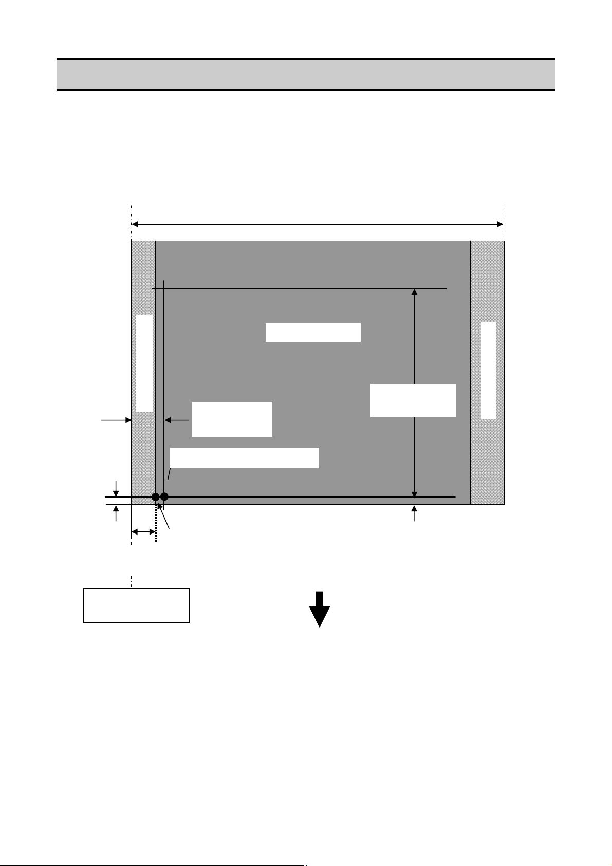
1-2. Printable Area
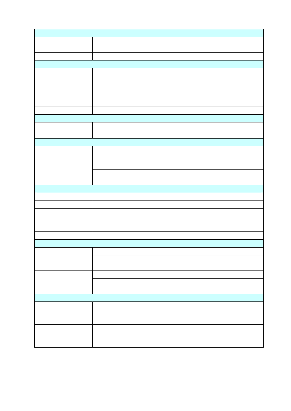
The printable area of the printer is as follows:
When media is set to the printer, it must be aligned with the media guide at the left of the printing
mechanism. Though the available maximum media width is 178 mm (7.01"), there are unprintable
areas on both sides: 2.5 mm (0.10") width is on the left side and 7.5 mm (0.30") width on the right
side as shown below.
The left side unprintable area applies for media of any size.
Media guide
2.5 mm (0.10")
Reference end
Maximum media width: 178 mm (7.01")
Unprintable area
Printable area
168 mm (6.61”)
7.5 mm (0.30")
Direction of media feed
CL-S6621 1-8
Page 13
Printing Position Accuracy
2
1
A
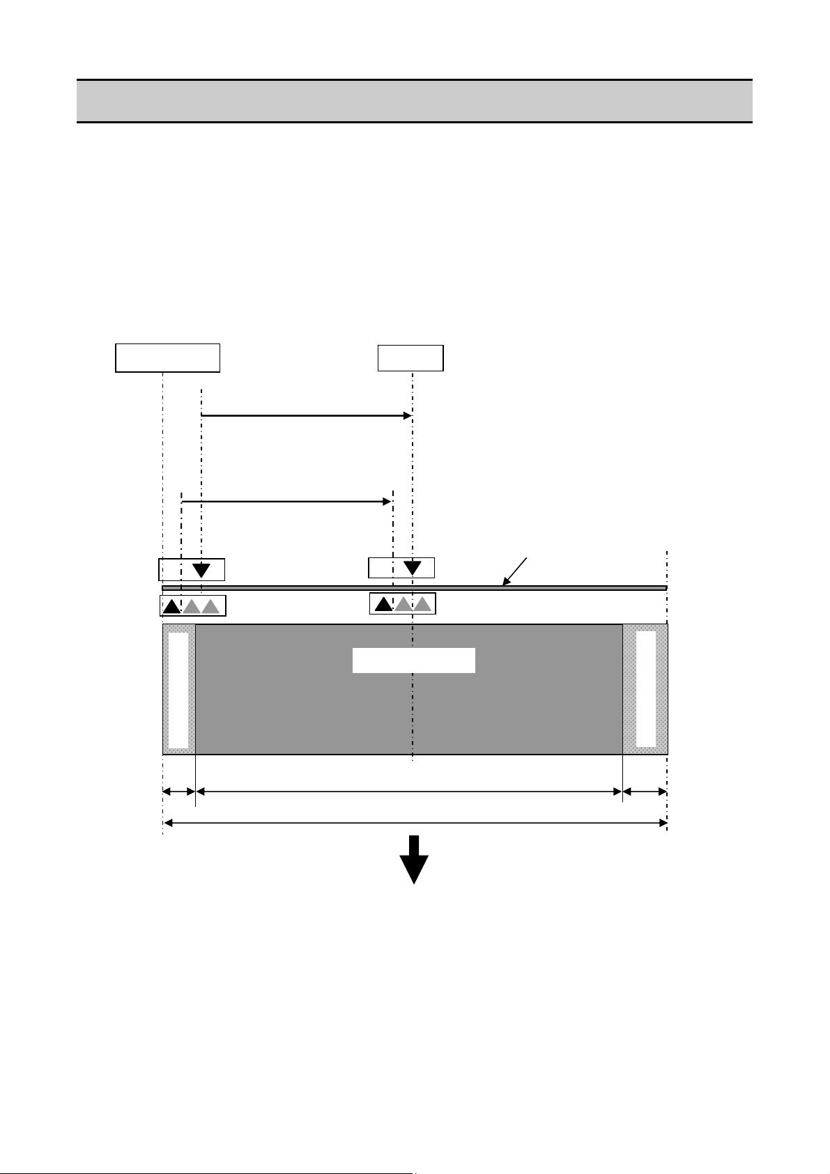
1-3. Printing Position Accuracy
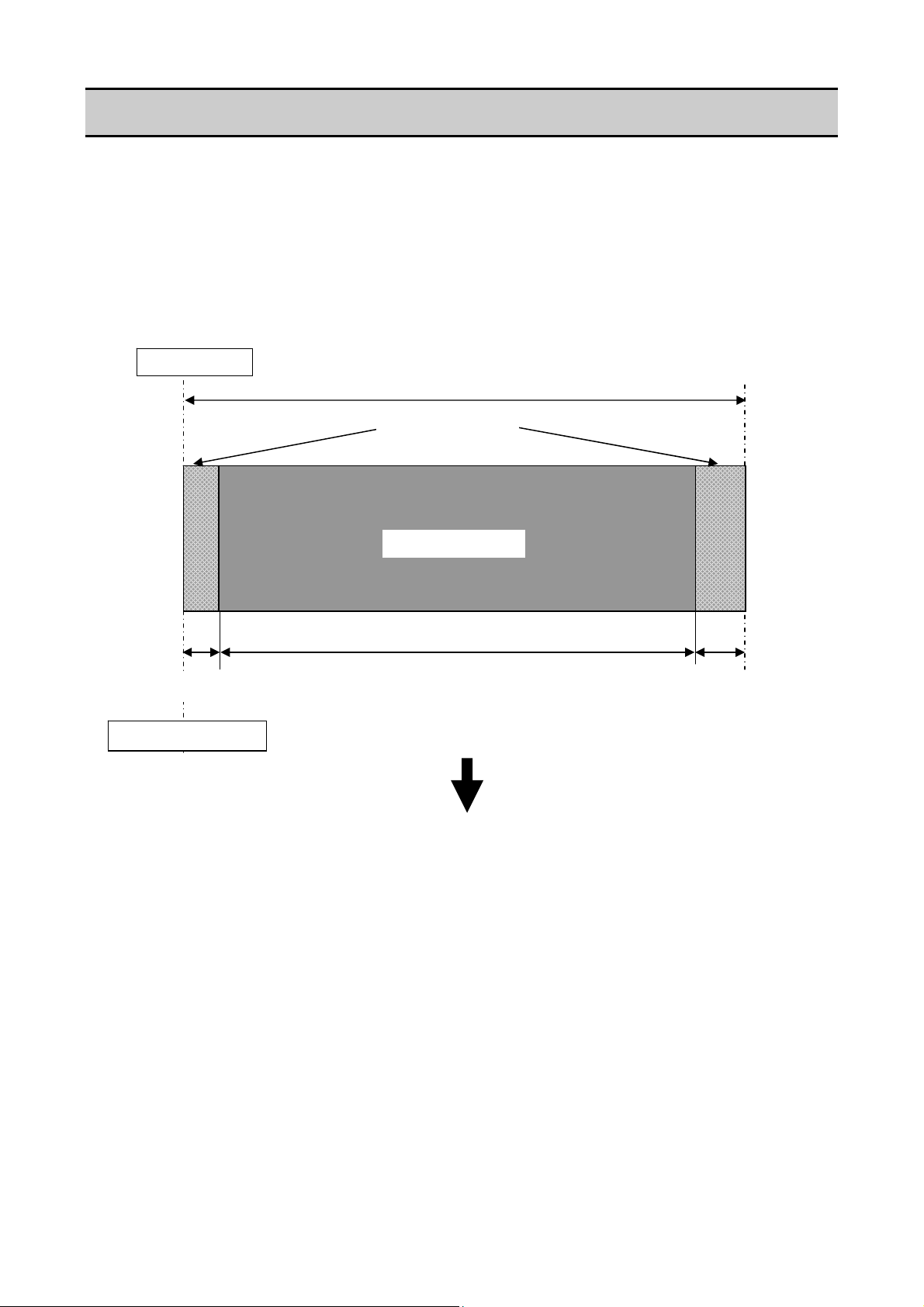
By default, the printing start position is 2.5 mm (0.10") from the left end of the media and 1 mm
(0.04") backward the leading edge of the label, U-shaped notch, or black mark.
2.5 mm (0.10") is the necessary value to avoid printing in the unprintable area as mentioned in
Printable Area".
“
The printing start position can deviate from the ideal position as follows:
Unprintable area
2.5 ± 1 mm*3
(0.10 ± 0.04")
Actual printing start position*
BCDEFG
1 mm (0.04")
2.5 mm
(0.10")
Ideal printing start position
Reference edge
(Paper guide)
*1: Actual printing start position. May deviates from the ideal one in the indicated range.
*2: Deviation of vertical positioning when printing position is set to 0.
*3: Deviation of horizontal positioning when printing position is set to 0.
*4: Deviation of vertical printing position when 100 mm is specified from the printing start
position.
Maximum media width: 178 mm (7.01")
Printable area
100 ± 2 mm*4
(39.4 ± 0.08")
1 ± 2 mm*
(0.04 ± 0.08")
Direction of media feed
Unprintable area
1-9 CL-S6621
Page 14
Adjustable Sensors
1-4. Adjustable Sensors
There are two media sensors; the upper sensor (transparent sensor) and the bottom sensor
(reflective sensor). The upper sensor is used to detect the labels on the liner or the U-shaped
notches of tag. The bottom sensor is used to detect the black marks on tag. Also, both sensors are
used to detect media end.
The mechanical adjustable range of both sensors is equal and they are adjusted at the same time
by turning the blue knob (“Gear Bevel Lead Screw U”).
For details about the media sensors, refer to “2-1-3 Label/Tag Detection Mechanism".
2.5 mm
Media guide
(0.10")
4.8 to 88.9 mm
(0.19 to 3.5")
(Moveable range of the
transparent sensor)
2.7 to 86.8 mm
(0.11 to 3.42")
(Moveable range of the
reflective sensor)
Unprintable area
Maximum media width: 178 mm (7.01")
Center
Printable area
168 mm (6.61”)
Direction of media feed
Media
Unprintable area
7.5 mm
(0.30")
CL-S6621 1-10
Page 15

CHAPTER 2
OPERATING PRINCIPLES
2-1 CL-S6621
Page 16

CHAPTER 2 OPERATING PRINCIPLES
TABLE OF CONTENTS
2-1. Operation of Each Mechanism .......................................................................................2-4
2-1-1. Locations and Functions of Motors, Sensors and Thermal Head ......................2-4
(1) “Unit, Ribbon” section................................................................................ 2-4
(2) Printing section.......................................................................................... 2-5
2-1-2. Media Feed Mechanism ..................................................................................... 2-6
2-1-3. Label/Tag Detection Mechanism ........................................................................ 2-7
2-1-4. Printing and Ribbon Feed Mechanism ............................................................... 2-10
2-1-5. Print Head Up/Down Detection Mechanism .......................................................2-13
2-1-6. Paper Near End Detection Mechanism ..............................................................2-14
2-1-7. Head Balance Adjustment Mechanism ..............................................................2-15
2-1-8. Media Offset Adjustment Mechanism................................................................. 2-16
2-1-9. Transparent/Reflective Sensor Travelling Mechanism ....................................... 2-17
2-2. Operation of Control Parts .............................................................................................. 2-18
2-2-1. Configuration of Printer ......................................................................................2-18
(1) AC power supply .......................................................................................2-19
(2) SA, Main PCB............................................................................................ 2-19
(3) Operation panel (SA, Opepane PCB)........................................................ 2-20
(4) Thermal print head (SA, Head).................................................................. 2-20
(5) Sensors ..................................................................................................... 2-20
(6) Motors........................................................................................................ 2-20
(7) SA, Ribbon PCB........................................................................................ 2-20
(8) SA, Relay PCB ..........................................................................................2-21
(9) Optional I/F................................................................................................ 2-21
2-2-2. Memory map ......................................................................................................2-22
2-2-3. Sensors ..............................................................................................................2-23
(1) Head up switch.......................................................................................... 2-23
(2) Transparent sensor and reflective sensor ................................................. 2-24
(3) Ribbon Sensor F/R.................................................................................... 2-26
(4) Head temperature sensor.......................................................................... 2-27
(5) PF motor temperature sensor.................................................................... 2-28
(6) Ribbon motor temperature sensor............................................................. 2-29
(7) Paper Near End sensor............................................................................. 2-30
2-2-4. Drivers ................................................................................................................ 2-31
(1) PF motor driver.......................................................................................... 2-31
(2) Ribbon motor driver................................................................................... 2-32
(3) Head driver................................................................................................ 2-33
(4) Buzzer driver ............................................................................................. 2-35
(5) Fan driver .................................................................................................. 2-35
2-2-5. Other circuits ...................................................................................................... 2-36
(1) Power supply circuit................................................................................... 2-36
(2) Reset circuit............................................................................................... 2-37
(3) Clock circuit ...............................................................................................2-37
CL-S6621 2-2
Page 17

(4) Ope-pane circuit ........................................................................................2-38
(5) USB I/F control circuit................................................................................ 2-38
(6) RS232C I/F circuit ..................................................................................... 2-39
(7) Option I/F circuit ........................................................................................2-39
(8) Peeler circuit (for optional peeler).............................................................. 2-40
(9) Cutter control circuit (for optional cutter) ................................................... 2-41
2-3. Operation Panel.............................................................................................................. 2-43
2-3-1. External view ...................................................................................................... 2-43
(1) Keys........................................................................................................... 2-43
(2) LEDs.......................................................................................................... 2-43
2-3-2. Operation using the keys ................................................................................... 2-44
(1) Normal operation....................................................................................... 2-44
(1-1) Sensor adjustment mode ..................................................................2-44
(1-2) Menu setting mode ...........................................................................2-45
(2) Test mode.................................................................................................. 2-46
(2-1) Self print mode.................................................................................. 2-46
(2-2) Hex dump mode................................................................................ 2-47
(3) Factory/Service mode................................................................................ 2-47
(3-1) General ............................................................................................. 2-47
(3-2) How to enter the Factory/Service Mode............................................ 2-48
(3-3) Factory/Service Mode menu table .................................................... 2-54
2-4. Interface.......................................................................................................................... 2-59
2-4-1. Serial Interface ...................................................................................................2-59
(1) Specifications............................................................................................. 2-59
(2) Signal line and pin assignment.................................................................. 2-59
(3) Protocol ..................................................................................................... 2-60
2-4-2. USB Interface ..................................................................................................... 2-61
(1) Specifications............................................................................................. 2-61
(2) Signal line and pin arrangement................................................................ 2-61
2-4-3. Parallel Interface (Option) ..................................................................................2-61
(1) Specifications............................................................................................. 2-61
(2) Signal line and pin assignment.................................................................. 2-62
(3) Parallel port status signals when an error occurs ......................................2-62
(4) Compatible timing specification................................................................. 2-63
2-3
CL-S6621
Page 18
Operation of Each Mechanism
2-1. Operation of Each Mechanism
This printer is a thermal transfer barcode & label printer comprised of the following mechanisms:
media feed, ribbon feed, label/tag detection, print head up/down detection, paper near end
detection, head balance adjustment, media thickness adjustment and transparent/reflective sensor
travel.
This section describes the operation of each of these mechanisms.
2-1-1. Locations and Functions of Motors, Sensors and Thermal Head
This printer has the following motors, sensors and thermal head.
(1) “Unit, Ribbon” section
Part name Description
SA Ribbon Motor F
(Front side)
SA Ribbon Motor R
(Rear side)
Ribbon Sensor F
(“SA, Ribbon Sensor”
on the front side)
Ribbon Sensor R
(“SA, Ribbon Sensor”
on the rear side)
SA Ribbon Motor F
SA Ribbon Motor R
This motor takes up ribbon. A thermistor is attached to the side of
this motor to detect the motor temperature.
This motor gives back tension to ribbon.
This sensor consists of two photointerrupters to detect if appropriate
tension is given to the front side ribbon.
It also detects a ribbon-running error.
This sensor consists of two photointerrupters to detect if appropriate
tension is given to the rear side ribbon.
It also detects the ribbon end status.
Ribbon Sensor R
("SA, Ribbon Sensor" on the rear side)
Ribbon Sensor F
("SA, Ribbon Sensor" on the front side)
CL-S6621 2-4
Page 19
Operation of Each Mechanism
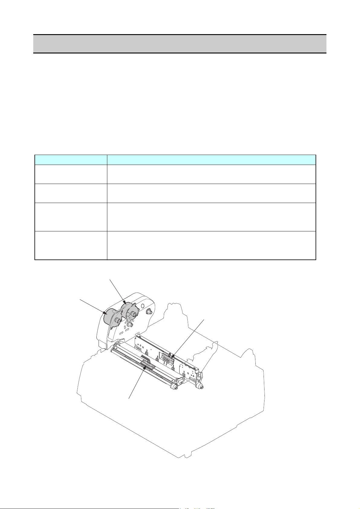
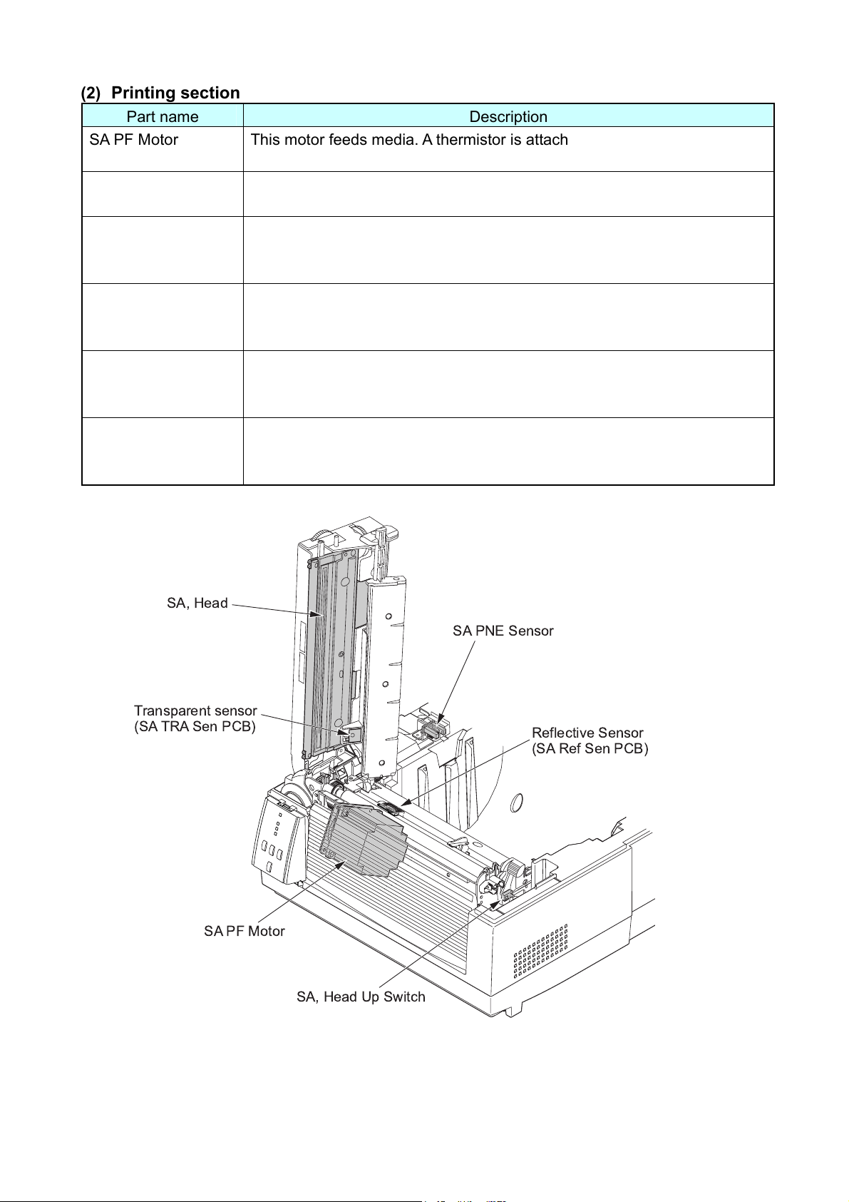
(2) Printing section
Part name Description
SA PF Motor This motor feeds media. A thermistor is attached to the side surface of this
motor to detect the motor temperature.
SA, Head Up Switch This switch is a mechanical lever switch to detect the print head position;
up or down.
Transparent Sensor
(Upper sensor)
This sensor is a photo sensor to detect the labels stuck on liner or
U-shaped notches on tag. It also detects the media end.
(SA TRA Sen PCB)
Reflective Sensor
(Bottom sensor)
This sensor is a photo sensor to detect the black marks on tag. It also
detects the media end.
(SA Ref Sen PCB)
SA, Head It consists of a head driver and thermal elements. Thermal elements are
heated to make printing on media. The thermal head incorporates a
thermistor to detect the thermal head temperature.
SA PNE Sensor
(Paper near end
This sensor is a photo sensor to detect a near end status of roll paper
installed.
sensor)
SA, Head
SA PNE Sensor
Transparent sensor
(SA TRA Sen PCB)
Reflective Sensor
(SA Ref Sen PCB)
SA PF Motor
SA, Head Up Switch
2-5 CL-S6621
Page 20
Operation of Each Mechanism
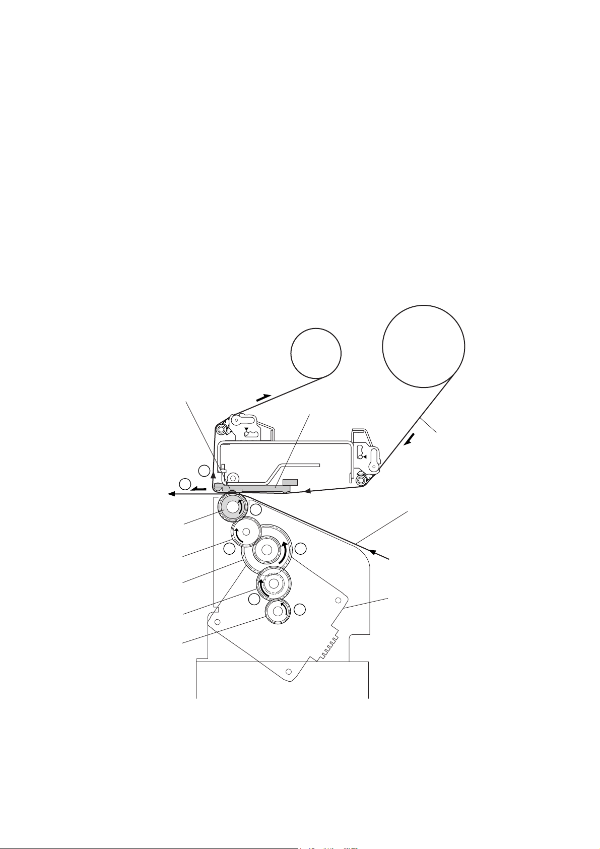
2-1-2. Media Feed Mechanism
The major components of the media feed mechanism are:
(a) SA PF Motor
(b) SA2_Platen
(c) Gear train
By setting the head block to the down position, media is pushed against the “SA2_Platen” by the
“SA, Head”.
As the “SA PF Motor” (stepping motor) turns counterclockwise viewing from the right side of the
printer, the “SA2_Platen” turns counterclockwise via the gear train (“Gear Reduction PF 1”, “Gear
Reduction PF 2” and “Gear Idle PF”) and media is fed forward by the friction force produced
between the “SA2_Platen” and the “SA, Head”.
When the “SA PF Motor” turns clockwise, media is fed backwards.
One step of the “SA PF Motor” feeds media by 1/16 mm (0.0025").
Gear Reduction PF 2
Gear Reduction PF 1
Thermal Elements
6
SA2_Platen
Gear Idle PF
Motor Gear
SA, Head
Ribbon
6
5
4
2
[Right side view]
3
1
Media
SA PF Motor
CL-S6621 2-6
Page 21
Operation of Each Mechanism
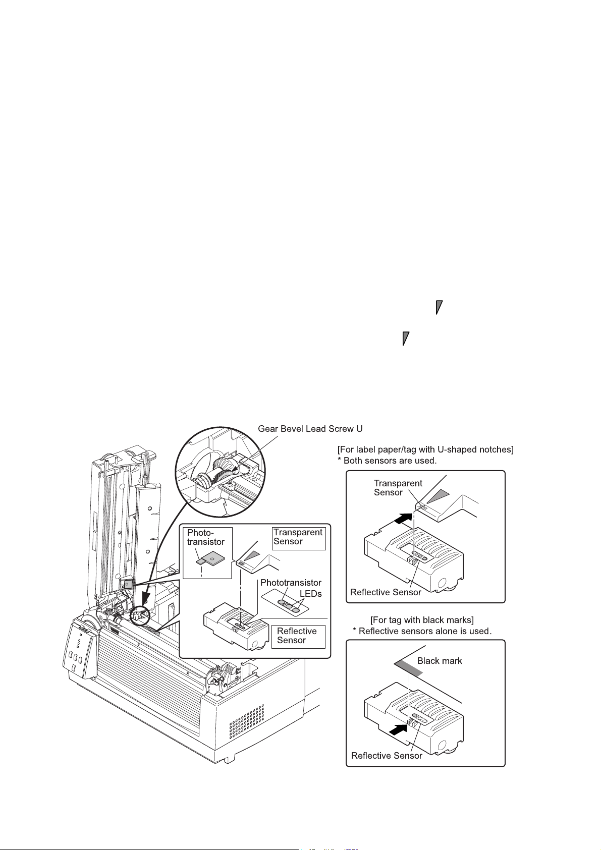
2-1-3. Label/Tag Detection Mechanism
The major components of the label/tag detection mechanism are:
(a) Reflective sensor (Bottom sensor) (SA Ref Sen PCB)
(b) Transparent sensor (Upper sensor) (SA TRA Sen PCB)
There are two movable sensors, the reflective sensor (bottom sensor) and the transparent sensor
(upper sensor). As you adjust the sensor position with the blue knob (“Gear Bevel Lead Screw U”),
both sensors move at the same time.
As shown in the figure below, the reflective sensor has two LEDs and one phototransistor. The
reflective sensor is used to detect black marks at the back of tag. On the other hand, the
transparent sensor is a phototransistor that will receive the transparent light from the LEDs through
the media. The transparent sensor is used to detect labels on liner or U-shaped notches of tag.
Both reflective and transparent sensors are used to detect the media end.
Aligning the sensors for label paper or tag with U-shaped notches:
For label paper, turn the blue knob (“Gear Bevel Lead Screw U”) to align the mark of the
transparent sensor at the center of label. (The transparent sensor and the reflective sensor move
at the same time.) For tags with U-shaped notches, turn it to align the mark with the U-shaped
notch.
Aligning the reflective sensor for tag with black marks:
For tag with black marks, turn the blue knob (“Gear Bevel Lead Screw U”) to align the left side
mark of the reflective sensor with the black mark of tag.
!
' " &
%
&
!
"#$
&
&
%
&
&
2-7 CL-S6621
Page 22
Operation of Each Mechanism
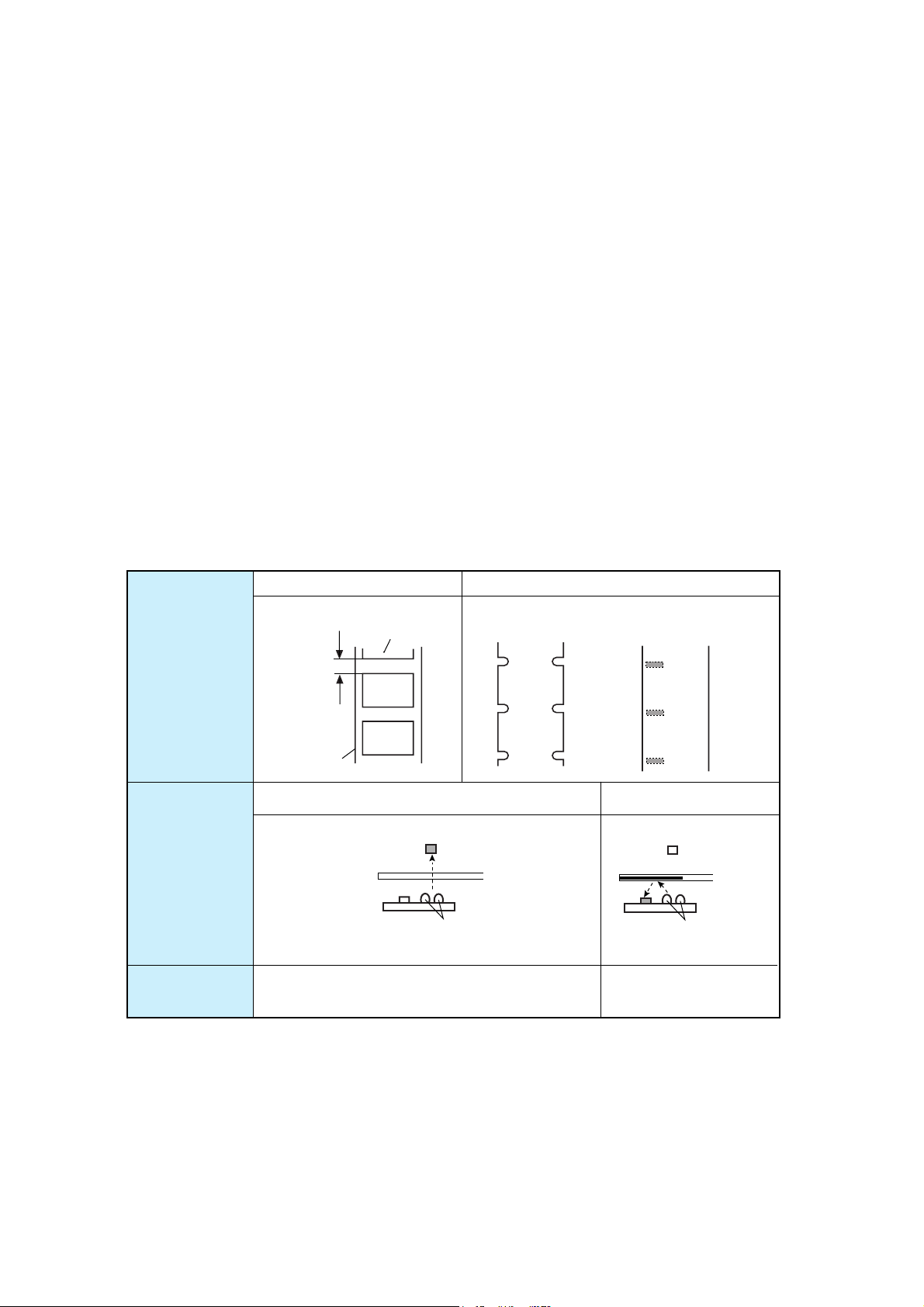
Detecting labels: (Media Sensor menu: “See Through”)
For detecting label, both reflective sensor and transparent sensor are used. Label paper passes
between both sensors. The light emitted from the LEDs of the reflective sensor passes through the
liner (base part of label paper) where no label is stuck on it, and the light reaches the transparent
sensor. Accordingly, the phototransistor of the transparent sensor turns ON. Meanwhile, in the
label part, the light is blocked by label and does not reach the phototransistor. So, the
phototransistor turns OFF. By sensing the output of the transparent sensor, the CPU on the Main
PCB can detect the label leading edge for printing.
Detecting U-shaped notches of tag: (Media Sensor menu: “See Through”)
For detecting U-shaped notches of tag, both reflective sensor and transparent sensor are used.
The U-shaped notches are detected in the same way as the label mentioned above, except that
the light is directly falls on the transparent sensor through the notch.
Detecting black marks on tag: (Media Sensor menu: “Reflect”)
For detecting black marks on tag, only the reflective sensor is used. Light emitted from the LEDs is
reflected by the tag (at other than the black mark) and reaches the phototransistor of the reflective
sensor. At the black mark, the light is not reflected. The CPU on the Main PCB detects the black
mark by sensing the output of the reflective sensor.
Label
Label
U-shaped
notch
Ta g
Black mark
Media
Sensor to be
used
Media Sensor
menu
Label gap
Liner
Transparent and Reflective sensors
Transparent sensor
Media
LEDs
Reflective sensor
See Trough
Reflective sensor
Media
LEDs
Reflective sensor
Reflect
CL-S6621 2-8
Page 23

Operation of Each Mechanism
Detecting continuous media: (Media Sensor menu: “None”)
For detecting continuous media, only the reflective sensor is used. In this case, only media end is
detected by the reflective sensor.
LED light amount control:
According to the media selected by the Media Sensor menu (“See Through”, “Reflect”, or “None”),
the amount of light is well controlled to detect the label/U-shaped notch, black mark, or continuous
media. The amount of light is as follows (the largest amount is for “See Through):
• Continuous media (None) < Black mark (Reflect) < Label/U-shaped notch (See Through)
2-9 CL-S6621
Page 24
Operation of Each Mechanism
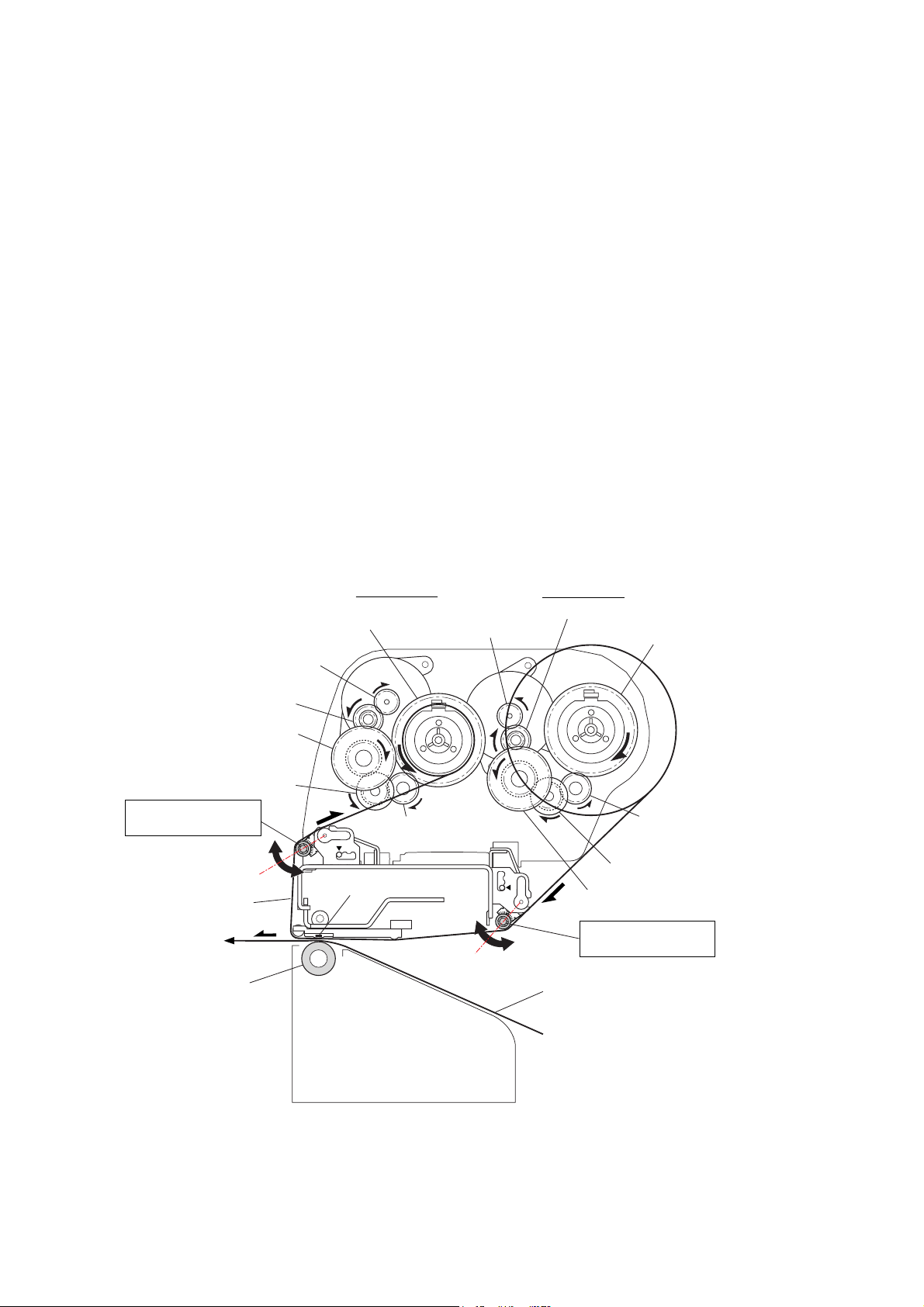
2-1-4. Printing and Ribbon Feed Mechanism
The major components of the printing and ribbon feed mechanism are:
(a) SA, Head (d) SA, Ribbon Tension Shaft F/R
(b) SA Ribbon Motor F/R (e) SA, Ribbon Sensor (Front/Rear)
(c) Ribbon gear train
Ink ribbon is set to the printer using the ribbon holders. Ribbon is supplied from the supply reel and
is taken up by the take-up reel with adequate ribbon tension, via the “SA, Ribbon Tension Shaft R”
and “SA, Ribbon Tension Shaft F”. The “SA, Ribbon Tension Shaft F/R” is always pushed outward
by the internal springs, and, when ribbon slacks, it moves outward. When ribbon tightens, it moves
inward. (Refer to the figures on the later pages.)
The same ribbon sensor is installed on the front and rear sides. The ribbon sensor on the front side
is used to detect the position of the “SA, Ribbon Tension Shaft F” (i.e., the ribbon tension on the
front side). While, the ribbon sensor on the rear side is used to detect the position of the “SA,
Ribbon Tension Shaft R” (i.e., the ribbon tension on the rear side).
The ribbon sensor on the front side is also used to detect a ribbon running condition, and that on
the rear side is used to detect the ribbon end.
On the front side, the “SA Ribbon Motor F” turns to take up ribbon. On the rear side, the “SA
Ribbon Motor R” turns to supply ribbon, while applying adequate back tension to ribbon to
eliminate ribbon slack.
Gear Ribbon Shaft F
Take-up Side
SA Ribbon Motor R
SA Ribbon Motor F
Gear Reduction Ribbon 1
Gear Reduction Ribbon 2
Gear Reduction Ribbon 3
SA, Ribbon Tension
Shaft F
Gear Idle Ribbon
Ribbon
Thermal Head
SA2_Platen
[Front]
Printing:
When printing with ink ribbon, ink on the ribbon is melted by the heated thermal element of the “SA,
Head” and is transferred on the media surface.
Supply Side
Gear Reduction Ribbon 1
Gear Ribbon Shaft R
Gear Idle Ribbon
Gear Reduction Ribbon 3
Gear Reduction Ribbon 2
SA, Ribbon Tension
Shaft R
Media
CL-S6621 2-10
Page 25

Operation of Each Mechanism
Taking up Ribbon:
Ribbon will be taken up on the front side as follows:
(1) As media is fed, ribbon is also fed by the friction force produced between media and the “SA,
Head”.
(2) Ribbon slacks and the ribbon sensor on the front side turns OFF as the “SA, Ribbon Tension
Shaft F” is pushed outward.
(3) The “SA Ribbon Motor F” starts to turn and ribbon is taken up.
(4) Ribbon tightens and the ribbon sensor on the front side turns ON. Then, the “SA Ribbon Motor
F” stops.
Supplying Ribbon:
On the rear side, the “SA Ribbon Motor R” turns to supply ribbon, while applying adequate back
tension. In the same way as on the front side, the ribbon sensor on the rear side detects the ribbon
tension to keep the ribbon tension constant. However, when printing is made and ribbon is fed, the
ribbon sensor on the rear side turns ON since ribbon is tightened at this time.
Reel Drive Mechanism:
Though the ribbon holders are directly installed in the reels, ribbon is connected to the reels via the
spring mechanism of the ribbon holders. This means that ribbon is taken up via the spring
mechanism when the “SA Ribbon Motor F”/”SA Ribbon Motor R” turns.
On the front side, the “SA Ribbon Motor F” turns in the clockwise direction viewing from the right
side of the printer, and the “Gear Ribbon Shaft F” (take-up reel) turns in the counterclockwise
direction via the “Gear Reduction Ribbon 1”, “Gear Reduction Ribbon 2”, “Gear Reduction Ribbon
3” and “Gear Idle Ribbon”. Thus, ribbon is taken up.
On the rear side, the “SA Ribbon Motor R” turns in the counterclockwise direction, and the “Gear
Ribbon Shaft R” (supply reel) turns in the clockwise direction via the “Gear Reduction Ribbon 1”,
“Gear Reduction Ribbon 2”, “Gear Reduction Ribbon 3” and “Gear Idle Ribbon”, Ribbon”. Thus,
ribbon is supplied.
2-11 CL-S6621
Page 26
Operation of Each Mechanism
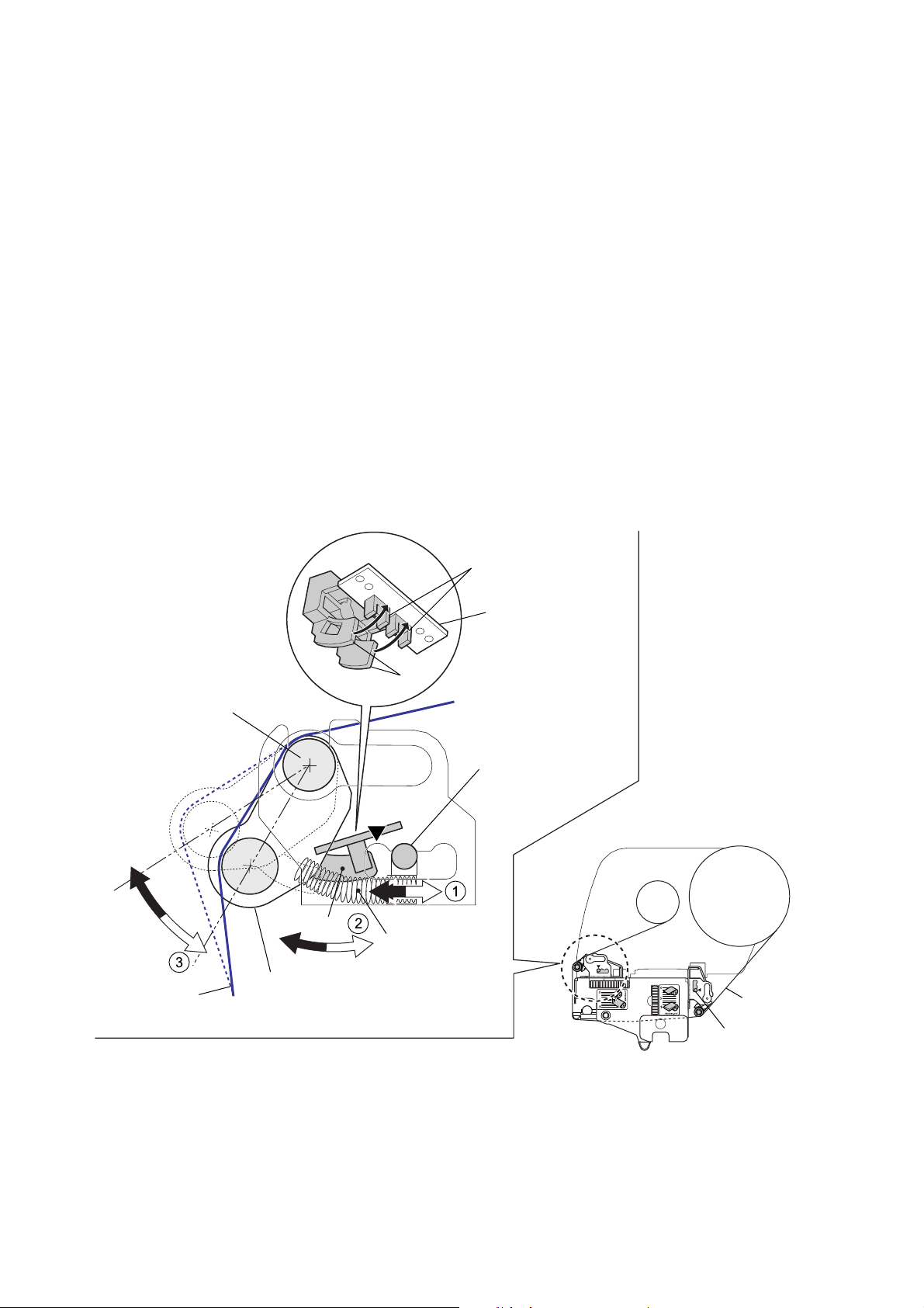
Detecting Ribbon Tension (Ribbon Sensors):
The same ribbon sensor is installed on the front and rear sides. Since the operation is the same on
both sides, the front side operation is explained here:
When ribbon is taken up, the ribbon tightens and the “SA, Ribbon Tension Shaft F” is pushed
inward (in the direction of “a”) by the ribbon. At this time, the claws “A” attached to the “SA, Ribbon
Tension Shaft F” are inserted into the photointerrupters of the “SA, Ribbon Sensor”, and the
photointerrupters turn OFF.
During printing, the ribbon is fed forward together with media and the ribbon will slack. This, the
“SA, Ribbon Tension Shaft F” is moved outward (in the direction of “b”) by the spring (“B”) force,
and the claws “A” come off the photointerrupters. So, the photointerrupters turn ON and the “SA
Ribbon Motor F” turns faster to take up the ribbon quickly. Then, the claws “A” are inserted into the
photointerrupters again, and the “SA Ribbon Motor F” resumes normal speed.
This cycle is repeated and constant tension is applied to the ribbon.
(The two claws “A” are arranged so that they are inserted into or released from the
photointerrupters with a slightly different timing. This function enables to finely control the ribbon
tension.)
On the rear side, during printing, ribbon will be tightened. If it is tightened, the ribbon sensor turns
ON and the “SA Ribbon Motor R” turns faster than normal speed to quickly supply ribbon.
Ribbon Sensor
SA, Ribbon Sensor
A
Supporting Point
Tension Adjustment
Knob (Front)
[Right side view]
b
Ribbon
Tension Adjustment
Knob (Rear)
Ribbon
A
a
SA, Ribbon
Tension Shaft F
B
Spring Ribbon
Tension (2 pcs.)
Tension Adjustment Mechanism:
To apply adequate ribbon tension, you can change the spring “B” force as follows:
The spring force is adjustable in 3 steps with the “Tension Adjustment Knob (Front/Rear)”. As you
move the knob toward the
T mark, the spring force becomes stronger since the spring “B” is
moved to the left in the above figure.
CL-S6621 2-12
Page 27
Operation of Each Mechanism
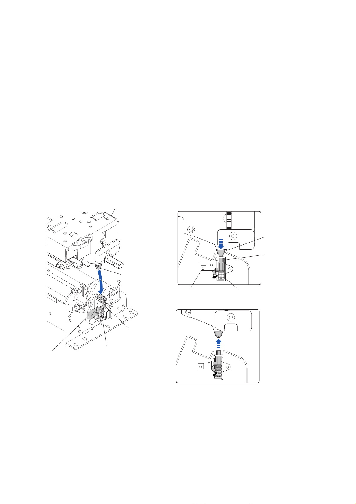
2-1-5. Print Head Up/Down Detection Mechanism
The component of the print head up/down detection mechanism is as follows:
(a) SA, Head Up Switch
(b) Pop Up Cover Frame
(c) Spring Pop Up
(d) Support Pop Up
The print head up/down detection mechanism detects the up (open)/down (close) status of the
“Unit, Head”.
When the “Unit, Head” is in the down position, the “Support Pop Up” (a part of the “Unit, Head”)
pushes down the top of the “Pop Up Cover Frame”, and the lever of the “SA, Head Up Switch” is
pushed. In this state, the “SA, Head Up Switch” turns ON and the signal line is in “Low” level.
While, the “Unit, Head” is in the up position, since the “Pop Up Cover Frame” is released from the
“Support Pop Up”, it pops up by the force of “Spring Pop Up” and the switch lever is set free. In this
state, the “SA, Head Up Switch” turns OFF and the signal line is in “High” level.
The CPU on the Main PCB detects up or down position of the “Unit, Head” by sensing the output of
the “SA, Head Up Switch.
Unit, Head
["Unit, Head" Down Position]
SA, Head Up Switch
Support Pop Up
Pop Up Cover Frame
Spring Pop Up
ON
SA, Head Up Switch
["Unit, Head" Up Position]
OFF
Support Pop Up
Pop Up Cover Frame
Spring Pop Up
2-13 CL-S6621
Page 28
Operation of Each Mechanism
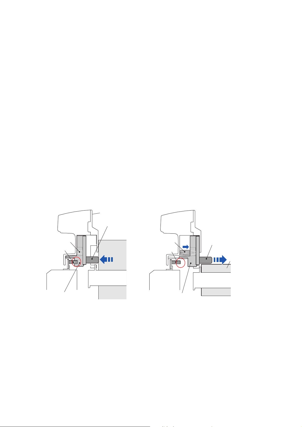
2-1-6. Paper Near End Detection Mechanism
The component of the Paper near end detection mechanism is as follows:
(a) SA PNE Sensor (A part of the main body)
(b) Lever PNE (A part of the “Roll Paper Holder”)
(c) Slider PNE (A part of the “Roll Paper Holder”)
(d) Spring PNE (A part of the “Roll Paper Holder”)
The paper near end sensor is used to detect a paper near end status of roll paper installed in the
printer.
The knob of the “Lever PNE” is pushed by the side of roll paper and the “Slider PNE” engages with
the “SA PNE Sensor” (fixed part on the main body). In this state, the “SA PNE Sensor”
(photointerrupter) turns OFF.
When printing proceeds and the diameter of roll paper is reduced to the preset paper near end
point, the knob of the “Lever PNE” that was pushed by the roll paper pops up, and the “Slider PNE”
comes off the “SA PNE Sensor”. In this state, the “SA PNE Sensor” (photointerrupter) turns ON.
The CPU on the Main PCB detects the ON/OFF status of the “SA PNE Sensor” (photointerrupter)
and judges if the roll paper reaches the near end status.
The paper near end position can be changed mechanically by sliding the knob of the “Lever PNE”
up or down.
Spring PNE
SA PNE Sensor
[Normal Status]
Roll Paper Holder
Lever PNE
Roll Paper
[PNE (Paper Near End) Status]
Spring PNE
SA PNE Sensor
Lever PNE
Roll Paper
Slider PNE
CL-S6621 2-14
Slider PNE
Page 29
Operation of Each Mechanism
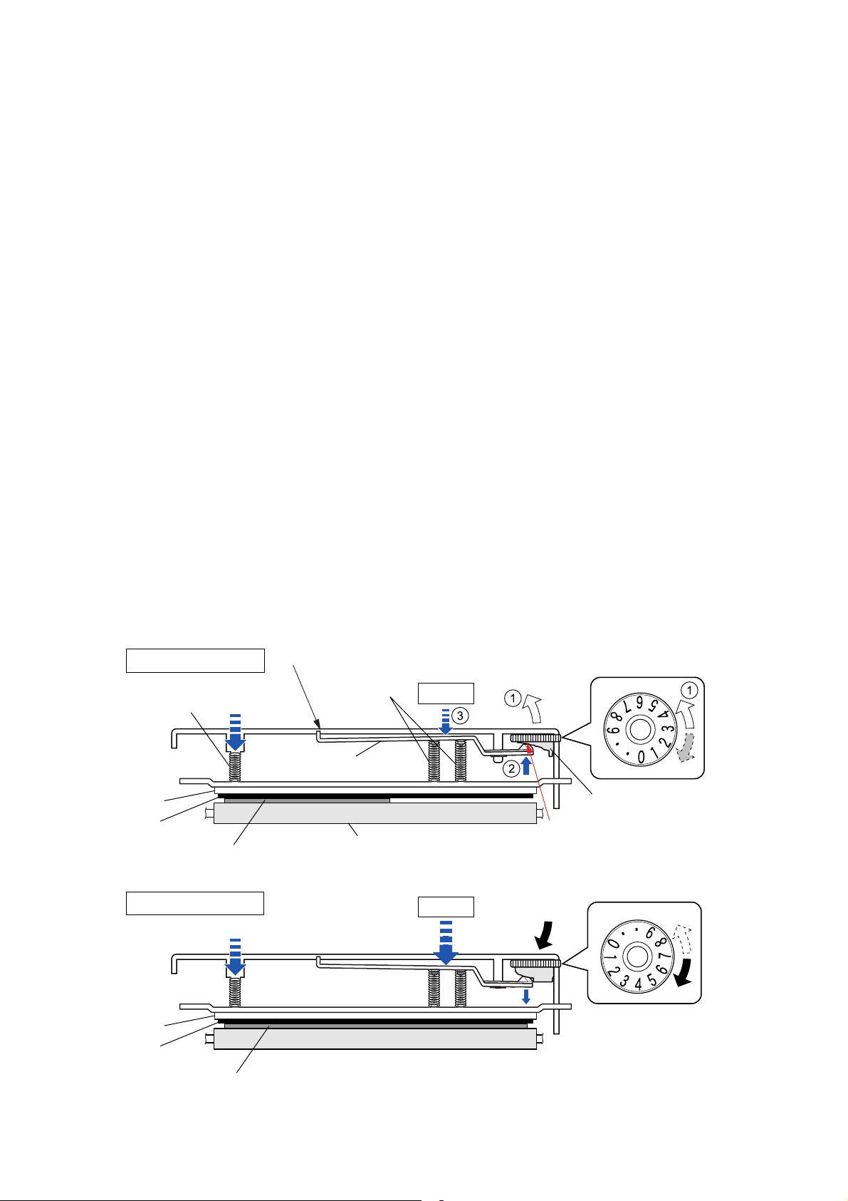
2-1-7. Head Balance Adjustment Mechanism
The major components of the head balance adjustment mechanism are:
(a) Cam Head Balance (c) Spring Head L/R
(b) Plate Head Balance
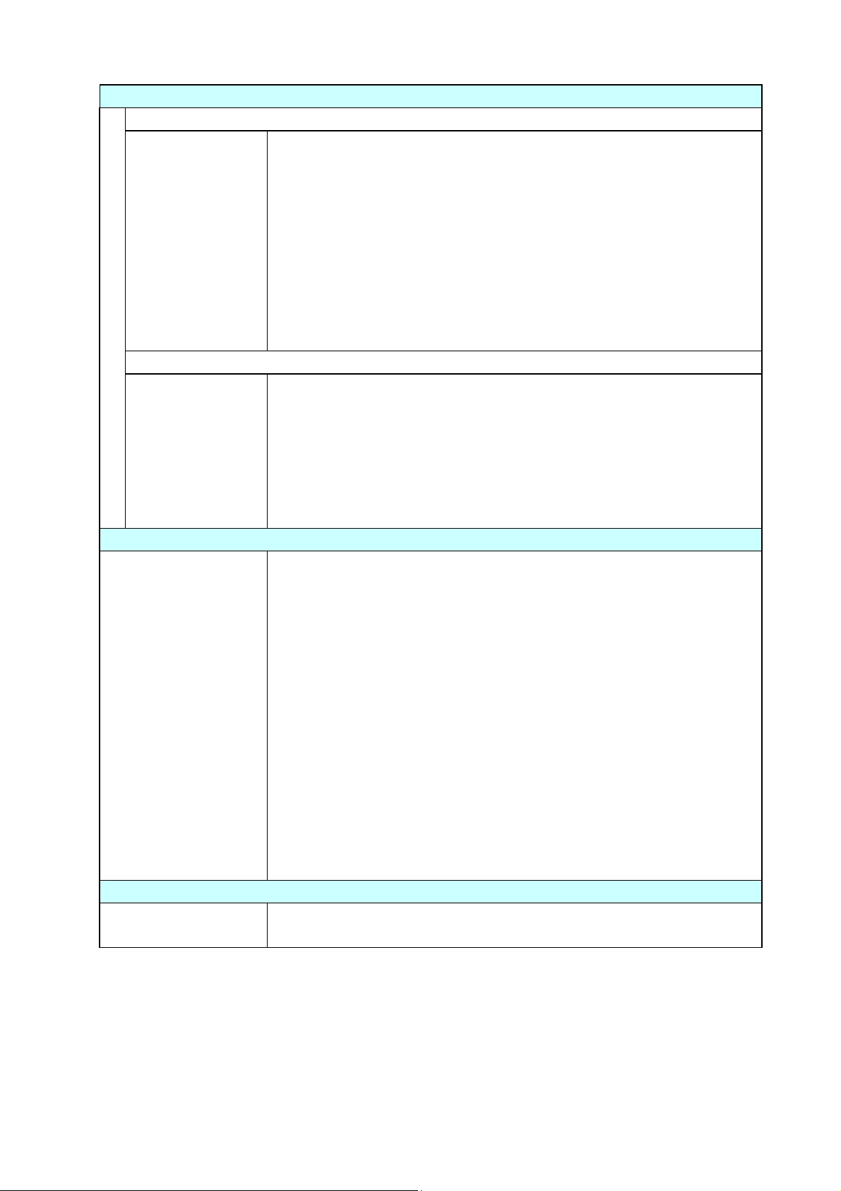
The head balance adjustment mechanism is used to eliminate uneven printing density on media.
The head balance adjustment is accomplished by changing the right side head pressure according
to media width to be used. To adjust, the blue Media width adjustment dial (“Cam Head Balance”)
is used. When narrow width media is used, the dial should be set toward “0” to give weaker
pressure. While, wide width media is used, it should be set toward “9” to give stronger pressure.
When narrow width media is used (need to give weak pressure):
The “Spring Head L” and “Spring Head R” (2 pcs.) act to press the “SA, Head” against the
“SA2_Platen”. For narrow width media, if the same pressure is given on both sides, since no media
exists on the right side of the “SA, Head”, the “SA, Head” will slant to the right, resulting in uneven
printing density. The part “A” of the “Plate Head Balance” is pushed against the cam part of the
“Cam Head Balance” by the force of “Spring Head R” and it moves up step by step () as the
Media width adjustment dial is turned toward “0” (). As it moves up, the “Spring Head R” is
pressed with weaker force by the “Plate Head Balance” (), and the right side pressure against
the “SA, Head” decreases, resulting in even printing density. You need to align the dial number
according to the media width to be used. (Smaller number for narrower media)
When wide width media is used (need to give strong pressure):
The same principle applies to wide media. However, in this case, the Media width adjustment dial
should be turned toward “9”. Then the part “A” of the “Plate Head Balance” moves down to apply
stronger pressure to the “SA, Head”. (Larger number for wider media)
For narrow media
Spring Head L
(Fixed)
Supporting point
Spring Head R
(Movable)
Weak
Toward "0"
Plate Head
Balance
SA, Head
Ribbon
For wide media
SA, Head
Ribbon
Media (Narrow width)
Media (Wide width)
SA2_Platen
Strong
T0ward "9"
Cam Head Balance
(Media Width Adjustment
A
Dial)
2-15 CL-S6621
Page 30

Operation of Each Mechanism
2-1-8. Media Offset Adjustment Mechanism
The major components of the media thickness adjustment mechanism are:
(a) Cam Head Adjust (c) Spring Head Holder
(b) SA Head Adjust Lever (d) Plate Holder Head
According to the softness of media, the thermal element position is displaced from the optimum
position. The head offset adjustment mechanism is used to correct this by moving the “SA Head”
back and forth a little. By performing the head adjustment properly, optimum printing quality is
obtained. (When shipping, the Media thickness adjustment dial is set to “1” for soft media.)
When soft media is used (thin thermal paper, label paper, etc.):
When soft media is used, the optimum position of the thermal elements will be nearly right above
the center of the “SA2_ Platen”. (In dial No. “1”, they are aligned with the platen center.)
When hard media is used (tag paper):
When hard media is used, the optimum position of the thermal elements will shift toward the front a
little from the center of the “SA2_Platen”, i.e. toward the left viewing from the right side of the
“SA2_ Platen” as shown below. As the optimum position varies according to the hardness of media,
it is necessary to adjust the Media thickness adjustment dial from “1” to up to “9” for optimum
printing. As the dial is turned (), the “SA Head Adjust Lever” swings up and down () as its
projection “A” moves along the groove of the dial.
The “Plate Holder Head” end is pinched by the “Spring Head Holder” at end “B” of the “SA, Head
Adjust Lever”. (Namely, both parts are connected via the “Spring Head Holder”.)
Therefore, as the “SA, Head Adjust Lever” swings up and down (), the “Plate Holder Head”
swings up and down accordingly (). With this movement of the “Plate Holder Head”, the thermal
element position slightly moves back and forth against the “SA2_Platen”.
Supporting
point
Ribbon
Media
SA2_Platen
For soft media
Plate Holder Head
For hard media
[Right side view]
SA Cover Frame (Fixed)
SA, Head
B
0
Spring Head Holder
0
9
B
9
[Section "B" upside-down view]
B
Groove
SA Head Adjust Lever
Supporting
point
Cam Head Adjust
(Media Thickness Adjustment Dial)
A
9
0
CL-S6621 2-16
Page 31

Operation of Each Mechanism
2-1-9. Transparent/Reflective Sensor Travelling Mechanism
The major components of the transparent/reflective sensor travelling mechanism are:
(a) Gear Bevel Lead Screw U (Blue) (d) Shaft Lead Screw (Upper/Lower)
(b) Gear Lead Screw L (e) Holder Sensor Adjust U (Transparent sensor)
(c) Gear train (f) Holder Sensor Adjust L (Reflective Sensor)
The transparent sensor is incorporated in the “Holder Sensor Adjust U” and the reflective sensor is
incorporated in the “Holder Sensor Adjust L”. Both sensor housings move to the right and left
simultaneously by turning the “Gear Bevel Lead Screw U” (blue).
Note that the sensor housings (“Holder Sensor Adjust U” and “Holder Sensor Adjust L”) are
engaged with the groove of respective “Shaft Lead Screw” (upper and lower). Therefore, they
move horizontally when the “Shaft Lead Screw” (upper and lower) turns.
When the “Gear Bevel Lead Screw U” (blue) turns in the direction as shown by the arrow (), the
“Screw Lead Screw” (upper) turns (“a”) and the “Holder Sensor Adjust U” moves to the right (“a’ ”).
At this time, via the gears (() and ()), the “Gear Lead Screw L” turns in the direction shown by
the arrow (), and the “Screw Lead Screw” (lower) turns (“b”) and the “Holder Sensor Adjust L”
moves to the right (“b’ “).
When the “Gear Bevel Lead Screw U” (blue) is turned reversely, the sensor housings move to the
left.
Gear Lead Screw L
Shaft Lead Screw
(Lower)
Holder Sensor Adjust L
(Reflective Sensor)
Gear Bevel Lead Screw U (Blue)
Shaft Lead Screw
a
(Upper)
b
a’
Holder Sensor Adjust U
(Transparent Sensor)
b’
2-17 CL-S6621
Page 32

Operation of Control Parts
r
r
r
2-2. Operation of Control Parts
2-2-1. Configuration of Printer
The following shows major configuration blocks.
(Option)
Auto Cutter
Cutter Moto
Cutter Motor
Temp. Sensor
(Option) Peeler
Peel Sensor
Head Up Switch
[SA, Head Up Switch]
Adjustable Paper Sensors
Transparent Sensor
[SA TRA Sen PCB]
Reflective Sensor
[SA Ref Sen PCB]
Thermal Head Temp. Sensor
PF Motor Temp. Sensor
[SA, Head]
[SA PF Motor]
Paper Near End Sensor
[SA PNE Sensor]
Operation Panel
(SWx4/LEDx4)
[SA, Opepane PCB]
(JM66720-*)
Ribbon Sensor F
[SA, Ribbon Sensor]
Ribbon Sensor R
[SA, Ribbon Sensor]
Ribbon Motor Temp. Sensor
[SA Ribbon Motor F]
SA Ribbon Motor F
SA Ribbon Motor R
Fan
CUTTER PCB
(PPS00065-*)
DC Motor
Driver
Cutter
Position
Sensor
SA, MAIN PCB (PPS00058-*)
UPD703111BGJ-13-UEV-A
Buzzer
EP2C5F256C8N
Fan
Driver
Stepping Moto
Driver x 2
SA, Ribbon PCB
(PPS00059-*)
CPU
128MHz
FPGA
SA, Relay PCB
(PPS00060-*)
AC Power Supply
PWT20005-* (100V)
PWT20006-* (200V)
Driver/Receiver
Control / C.G.
F-ROM (64Mbits)
F-ROM (64Mbits)
S-DRAM (256Mbits)
Stepping Moto
RS232C
RS232C
USB2.0
Controller
C.G.
Driver
(Option)
Interface Board
IEEE1284
Ethernet I/F
(Standard type)
Ethernet I/F
(Multi-function type)
Wi-Fi I/F
RS232C
USB 2.0
(High Speed)
Thermal Print Head
(203dpi)
[SA, Head]
SA PF Motor
CL-S6621 2-18
Page 33

Operation of Control Parts
Major functions of individual components are described below:
(1) AC power supply
Consists of a fuse, a filter circuit to eliminate external electric noise, and a switching type
regulator to transform an AC input to +24V DC output required to drive the printer.
(2) SA, Main PCB
Controls the entire operations of the printer. It consists of CPU, Flash ROM, S-DRAM, FPGA
(Field-Programmable Gate Array), driver circuits, etc.
(a) CPU
The CPU is a microprocessor with 32-bit architecture. The clock fed to the CPU is 16 MHz.
The CPU internally multiplies this 16 MHz by 8 times and uses 128 MHz clock. The CPU
includes cache memory, RAMs, DMA controller, serial I/F, USB function controller, A/D
converter, etc.
(b) Flash ROM
A flash ROM of 64M bits (8M bytes) that stores the firmware and CG (character generator)
(c) S-DRAM (Synchronous dynamic RAM)
An S-DRAM of 256M bits (32M bytes) that is used as working area, input buffer and
download buffer.
(d) FPGA
The FPGA (Field-Programmable Gate Array) incorporates a control circuit for the interface
I/O port, motors, print head, etc.
(e) Serial I/F (RS-232C Driver/Receiver)
This is a circuit to transmit and receive serial data between the printer and the host.
Serial I/F, USB I/F, Parallel I/F (Option), Wired LAN (Option) or Wireless LAN (Option) is
automatically selected when data is received.
(f) USB I/F (High-speed USB2.0 Controller)
This is a circuit to transmit and receive serial data between the printer and the host using
the high-speed USB2.0 I/F.
Serial I/F, USB I/F, Parallel I/F (Option), Wired LAN (Option) or Wireless LAN (Option) is
automatically selected when data is received.
(g) Stepping motor driver
This is a circuit to drive the “SA PF Motor”. The “SA PF Motor” is a stepping motor.
(h) Buzzer
The buzzer is driven when an alarm, etc. occurs.
2-19 CL-S6621
Page 34

Operation of Control Parts
(3) Operation panel (SA, Opepane PCB)
Used to indicate the operating status of the printer and to set specifications. It consists of 4
keys and 4 LEDs.
(4) Thermal print head (SA, Head)
Makes printing on paper. The number of thermal elements (dots) is as follows. The thermal
print head includes the print head driver circuit.
•1344 dots
(5) Sensors
The following 9 sensors are used in the printer:
Sensor name Description
Head Up Switch
A mechanical lever switch.
(SA, Head Up Switch)
Transparent Sensor A photo sensor using a phototransistor. (On the “SA
TRA Sen PCB”.)
Reflective Sensor A photo sensor consisting of 2 LEDs and 1
phototransistor. (On the “SA Ref Sen PCB”.)
Ribbon Sensor F Photo sensors (2 pcs.) using photointerrupters.
(Located on the “SA, Ribbon Sensor” on the front side.)
Ribbon Sensor R Photo sensors (2 pcs.) using photointerrupters.
(Located on the “SA, Ribbon Sensor” on the rear side.)
Thermal Head Temperature
A thermistor incorporated in the “SA, Head”.
Sensor
PF Motor Temperature Sensor A thermistor attached to the “SA PF Motor”.
Ribbon Motor Temperature Sensor A thermistor attached to the “SA Ribbon Motor F” (the
front side of ribbon motor).
Paper Near End Sensor A photo sensor using a photointerrupter. (On the “SA
PNE Sensor”.)
(6) Motors
Three motors are used.
- The “SA PF Motor” is a stepping motor to feed media.
- The “SA Ribbon Motor F” and “SA Ribbon Motor R” are stepping motors to take up and
supply ribbon, respectively.
(7) SA, Ribbon PCB
Controls the operations of the “Unit, Ribbon”.
(a) Stepping motor driver
This is a circuit to drive the “SA Ribbon Motor F” on the front side for taking up ribbon and
the “SA Ribbon Motor R” on the rear side for supplying ribbon. Both are stepping motors.
CL-S6621 2-20
Page 35

(b) Fan driver
This is a fan drive circuit. The fan is used to cool both “SA Ribbon Motor F” and “SA
Ribbon Motor R”. When the temperature of the “SA Ribbon Motor F” exceeds a certain
value, the fan starts to rotate.
(8) SA, Relay PCB
Relays the signals between the “SA, Main PCB” and an optional I/F board.
(9) Optional I/F
(a) Parallel I/F (IEEE1284) (Option)
This is the parallel I/F to transmit and receive parallel data between the printer and the host.
It supports Centronics Compatible mode, NIBBLE mode and ECP mode.
Parallel I/F, serial I/F, or USB I/F is automatically selected when data is received.
(b) Wired LAN I/F (Option)
This is a circuit which supports Ethernet protocol. LAN connection is possible.
(c) Wireless LAN I/F (Option)
This is a circuit which supports wireless LAN protocol (IEEE802.11n/IEEE802.11g/
EEE802.11b).
Operation of Control Parts
2-21 CL-S6621
Page 36

Operation of Control Parts
2-2-2. Memory map
0000000
001FFFF
0100000
0103FFF
0104000
0105FFF
0106000
0107FFF
0108000
011FFFF
0120000
030FFFF
0310000
04FFFFF
0710000
074FFFF
H
H
H
H
H
H
H
H
H
Command RAM
(Built-in CPU)
Boot Loader (1)
Setting Information
(User Settings)
Setting Information
(Factory-set Settings)
CPU
Boot Loader (2)
H
H
Firmware (Datamax)
H
H
Firmware (Zebra)
H
H
H
FPGA Data
8M bytes
Flash ROM
07E0000
07EFFFF
07F0000
07FFFFF
0800000
27FFFFF
8000000
80FFFFF
H
Service Information (Backup)
H
H
Service Information
H
H
Firmware (about 400K bytes)
Receiving Buffer (16K bytes x 4)*
SDRAM
32M bytes
Command Buffer (128K bytes)
Others
H
*: 16K bytes for each I/F
(USB, IEEE1284, Serial,
USB for optional I/F)
H
H
I/O
FPGA
C000000
C3FFFFF
C400000
C7FFFFF
F800000
F8FFFFF
FFFB000
FFFEFFF
FFFF000
FFFFFFF
H
H
H
H
H
H
H
Download Area (4MByte)
Kanji Font (4MByte)
I/O
FROM
8MByte
USB2.0 Controller
Data RAM (Built-in CPU)
H
H
H
I/O (Built-in CPU)
CPU
CL-S6621 2-22
Page 37

Operation of Control Parts
2-2-3. Sensors
(1) Head up switch
The “SA, Head Up Switch” is used to detect the head position (up or down).
When the “Unit, Head” is closed (in the down position), the ”Support Pop Up” of the “Unit,
Head” pushes the “Pop Up Cover Frame” and the “SA, Head Up Switch” pushes the lever of
the “SA, Head Up Switch” and the switch turns ON. Then, pin 117 (HDUSW) of U1A (CPU)
goes "Low" level.
When the “Unit, Head” is opened (in the up position), the ”Support Pop Up” is disengaged from
the “Pop Up Cover Frame”, the lever of the “SA, Head Up Switch” is set free, and the switch
turns OFF. Then, pin 117 (HDUSW) of U1A (CPU) goes "High" level.
R80
C99
+3.3V
R78
[SA, Main PCB]
["Unit, Head" Down Position]
SA, Head Up Switch
J11
(Blue)
ON
SA, Head Up Switch
Head Up Switch
1
2
Support Pop Up
Pop Up Cover Frame
Spring Pop Up
U1A
CPU
PDH3
117
HDUSW
Head Up: High
Head Down: Low
Unit, Head
Support Pop Up
["Unit, Head" Up Position]
Pop Up Cover Frame
SA, Head Up Switch
Spring Pop Up
OFF
2-23 CL-S6621
Page 38

Operation of Control Parts
(2) Transparent sensor and reflective sensor
The transparent sensor (“SA TRA Sen PCB”) is used to detect the label stuck on liner and the
U-shaped notch on tag. On the other hand, the reflective sensor (“SA Ref Sen PCB”) is used to
detect the black mark printed on the bottom surface of tag. Both sensors are also used to
detect the media end.
The upper side transparent sensor is the phototransistor, and the lower side reflective sensor
consists of 2 LEDs and 1 phototransistor. Media passes between these sensors.
Transparent sensor
output sensing terminal
Reflective sensor output
sensing terminal
U1A
CPU
ANI0
ANI1
U14
FPGA
B4_34
R14
B4_33
R13
From
U1A CPU
SD ATA
SCLK
DACCS
TRAMON
5
C96
REFMON
6
TSNSCTL1
TSNSCTL0
U7
D/A Converter
12
DI
11
CK
10
CSB
BH2227
C97
AO1
AO2
AO3
AO4
R65
U20B
7
BA2904
U20A
1
BA2904
Q9
DTC114EM
DTC114EM
PSNSLED
2
5
+
6
-
R72
3
+
2
-
Q10
Q7
DTC114EM
R66
R70
R73
R76
R74
R75
R68
R69
Q8
DTC114EM
R67
+3.3V
J9
(White)
(White)
+5V
Q6
2SC5658
R71
[SA, Main PCB]
Transparent Sensor
[SA TRA Sen PCB]
1
2
3
J8
1
2
3
4
5
4
[SA Ref Sen PCB]
Reflective Sensor
Transparent sensor (used for detecting the label or U-shaped notch):
When the liner without label stuck on it passes between both sensors, the light emitted from
the LEDs reaches the transparent sensor, passing through the liner. Thus, the transparent
sensor (phototransistor) conducts and the voltage corresponding to the amount of light is
applied to pin 5 (TRAMON) of U1A (CPU).
Meanwhile, when the liner with the label stuck on it passes between both sensors, the light is
blocked by the label and the transparent sensor (phototransistor) turns OFF. Thus, pin 5
(TRAMON) of U1A (CPU) goes "Low" level. From the difference in these levels at pin 5
(TRAMON) of U1A (CPU), U1A (CPU) can detect the leading edge (arrival) of the label on the
liner.
When media runs out, the light directly falls on the transparent sensor and media end is
detected. In this case, pin 5 of U1A (CPU) will go "High" level.
Media
CL-S6621 2-24
Page 39

Operation of Control Parts
When the transparent sensor is conducted, the voltage at pin 5 (TRAMON) varies depending
on the characteristics of the light receiving element (phototransistor) of the transparent sensor
and other factors. To solve this problem, U14 (FPGA) outputs TSNSCTL0 (pin R13) and
TSNSCTL1 (pin R14) signals to turn ON/OFF Q8 and Q7 to connect/disconnect R69 and R68
(voltage dividing resistors) to minimize the difference in level at pin5 (TRAMON).
The current flowing into the LEDs is determined by the data sent from the CPU to the
digital-to-analog converter (U7). The digital-to-analog converter converts the data received
from the CPU, and then outputs a resoultant level at pin 2. The base current of the transistor
Q6 is determined by this level. This means that the current flowing into the LEDs is also
determined by this level. In the actual control, the CPU changes data (for controlling the LED
current) to keep the level at pin 5 (TRAMON) of CPU constant.
Reflective sensor (used for detecting the black mark on tag):
When tag with black marks is used, light is reflected by the tag. In the place where no black
mark is there, the phototransistor of the reflective sensor conducts and the voltage
corresponding to the amount of light is applied to pin 6 (REFMON) of U1A (CPU).
When the light falls on the black mark, no light is reflected. In this case, the lower
phototransistor turns OFF and pin 6 (REFMON) of U1A (CPU) will go “Low” level.
When media runs out, the light is not reflected and no light falls on the reflective sensor. In this
case, pin 6 (REFMON) of CPU will go “Low” level and media end is detected.
When the reflective sensor is conducted, the voltage at pin 6 (REFMON) varies depending on
the characteristics of the light receiving element (phototransistor) of the reflective sensor and
other factors. To solve this problem, U14 (FPGA) outputs TSNSCTL0 (pin R13) and
TSNSCTL1 (pin R14) signals to turn ON/OFF Q10 and Q9 to connect/disconnect R75 and R74
(voltage dividing resistors) to minimize the difference in level at pin6 (REFMON).
As to the current control of the LEDs, the operation is the same as for the transparent sensor
mentioned above.
2-25 CL-S6621
Page 40

Operation of Control Parts
(3) Ribbon Sensor F/R
The ribbon sensor F (“SA, Ribbon Sensor” mounted on the front side) is used to detect the
ribbon tension on the front side as well as ribbon running. While, the ribbon sensor R (“SA,
Ribbon Sensor” mounted on the rear side) is used to detect the ribbon tension on the rear side
as well as the ribbon end. These sensors are photointerrupters.
Front (Take-up side)
PT501
PS501
Ribbon Sensor1
1
2
3
4
(SA, Ribbon Sensor)
Ribbon Sensor2
R501
Rear (Supply side)
PT501
1
2
(Same as above circuit)
3
4
(SA, Ribbon Sensor)
U1A
CPU
PCM0
PCM2
PCM3
PCM5
RIBSENS_A1
34
RIBSENS_A2
32
RIBSENS_B1
31
RIBSENS_B2
29
U2B
11
6
U2D
U2A
3
5
U2C
8
12
2
U21D
9
U21F
12
+3.3V
J102
J19
R137
R138
R136
C176
C177
RA20
C178
U21C
5
6
9
8
11
10
U21E
13
C175
R139
18-20 18-20
[SA, Main PCB]
1
1
13
13
SENS_A1
14
14
SENS_A2
15
15
SENS_B1
16
16
SENS_B2
[SA, Ribbon PCB]
+3.3V
+3.3V
J105
+3.3V
J104
1
2
3
4
1
2
3
4
Ribbon sensor F:
The ribbon sensor F is used to keep the ribbon tension on the front side constant. When
printing starts, ribbon is fed and then the front side ribbon slacks. Then, the claws of the “SA,
Ribbon Tension Shaft F” come off the photointerrupters on the “SA, Ribbon Sensor” and the
photointerrupters turn ON. Thus, pin 34/32 (RIBSENS_A1/A2) of U1A (CPU) goes "High" level.
In this case, U1A (CPU) increases the revolution speed of “SA Ribbon Motor F” to take up the
slack of ribbon. As a result, ribbon tightens and the claws are inserted into respective
photointerrupters. Thus, pin 34/32 (RIBSENS_A1/A2) of U1A (CPU) goes "Low" level. Then,
U1A (CPU) slows down the revolution speed of “SA Ribbon Motor F”. During printing, this cycle
is repeated and constant ribbon tension is maintained.
If ribbon is not correctly fed during printing, the ON/OFF state of the photointerrupters on the
“SA, Ribbon Sensor” becomes improper. Thus, the CPU can detect an abnormal ribbon feed.
Ribbon sensor R:
The ribbon sensor R is used to keep the ribbon tension on the rear side constant. When
printing starts, ribbon is fed and the rear side ribbon tightens. Then, the claws of the “SA,
Ribbon Tension Shaft R” are inserted into respective photointerrupters on the “SA, Ribbon
Sensor” and the photointerrupters turn OFF. Thus, pin 31/29 (RIBSENS_B1/B2) of U1A (CPU)
goes "Low" level. In this case, U1A (CPU) increases the revolution speed of “SA Ribbon Motor
R” to supply ribbon faster. As a result, ribbon slacks and the claw comes off the
photointerrupter. Thus, pin 31/29 (RIBSENS_B1/B2) of U1A (CPU) goes "High" level. Then,
U1A (CPU) slows down the revolution speed of the “SA Ribbon Motor R”. During printing, this
cycle is repeated and constant ribbon tension is maintained.
When ribbon runs out, the ON/OFF state of the photointerrupters on the “SA, Ribbon Sensor”
becomes unchangeable. Thus, the CPU can detect the ribbon end.
PS502
R502
CL-S6621 2-26
Page 41

Operation of Control Parts
(4) Head temperature sensor
The head temperature sensor is used to detect the temperature of the “SA, Head”. This sensor
is a thermistor incorporated in the “SA, Head”. Since the resistance of the thermistor changes
according to a temperature change, the voltage at pin 7 (HDTMP) of U1A (CPU) changes
accordingly. The CPU senses the voltage at pin 7 (HDTMP) to detect the head temperature.
According to the temperature of the “SA, Head”, the CPU controls the printing pulse width
applied to the thermal elements to keep the printing density constant.
U1A
CPU
ANI2
7
HDTMP
R54
C82
+3.3V
R53
HDTMP
J5
SA, Head
Head Temp.
8
5
Thermistor
U14
FPGA
B2_28
nTEMP_ENABLE
C11
B2_27
nTEMP_ERROR
C6
+3.3V
R40
R41
R42
Error: Low
TEMP ERROR Detection
+3.3V
HDTMP
C41
U16B
5
+
6
-
BA2903SFV
[SA, Main PCB]
7
R39
Printing operation when the head temperature rises:
If the head temperature reaches 70°C (158°F), printing stops after printing the current label. In
this case, the PRINT LED and CONDITION LED simultaneously blink on the operation panel.
When the temperature of the “SA, Head” falls below 60°C (140°F), the LEDs stop blinking and
printing will be resumed.
Printing
Printing
60°C
(140°F)
Printing
(Stop)
(Stops)
70°C
(158°F)
For further safety, an abnormally high temperature detection circuit is provided. In case this
circuit is activated, the System error is displayed, and the printer stops.
The comparator U16B detects if the level at pin 5 (HDTMP) (i.e., the temperature of the “SA,
Head”) exceeds a certain reference level determined by the output from pin C11
(nTEMP_ENABLE) of U14 (FPGA) (i.e., the predetermined allowable limit temperature). If it
does, nTEMP_ERROR at pin C6 goes “Low” level and this signal is fed to U14 (FPGA). Then,
the System error is displayed and the printer stops. At this time, nTEMP_ENABLE at pin C11 is
set to “Low” level so that nTEMP_ERROR is securely maintained at “Low” level. (To clear the
System error, you need to turn OFF the printer once and then turn it ON.)
2-27 CL-S6621
Page 42

Operation of Control Parts
(5) PF motor temperature sensor
The PF motor temperature sensor is used to detect the temperature of the “SA PF Motor”. This
sensor is a thermistor bonded to the “SA PF Motor”. Since the resistance of the thermistor
changes according to a temperature change, the voltage at pin 8 (PFTMP) of U1A (CPU)
changes accordingly. The CPU senses the voltage at pin 8 (PFTMP) to detect the PF motor
temperature.
U1A
CPU
ANI3
PFTMP
8
R64
C94
+3.3V
R63
J7
2
1
SA PF Motor
Thermistor
M
U14
FPGA
B2_28
nTEMP_ENABLE
C11
+3.3V
R40
R41
R42
TEMP ERROR Detection
U16A
PFTMP
C41
3
+
2
-
BA2903SFV
+3.3V
R39
1
B2_27
nTEMP_ERROR
C6
Error: Low
[SA, Main PCB]
Printing operation when motor temperature rises:
When the temperature of the “SA PF Motor” rises above 90°C (194°F), printing speed is
reduced to avoid overheating. If it reaches 95°C (203°F), the “SA PF Motor” stops after printing
the current label. In this case, the PRINT LED and CONDITION LED alternately blink on the
operation panel.
When the temperature of the “SA PF Motor” falls below 85°C (185°F), the LEDs stop blink and
printing will be resumed.
Normal speed
Normal speed
85°C
(185°F)
Normal speed
(Stop)
90°C
(194°F)
Low speed
(Stop)
(Stops)
95°C
(203°F)
For further safety, an abnormally high temperature detection circuit is provided. In case this
circuit is activated, the System error is displayed, and the printer stops.
The comparator U16A detects if the level at pin 8 (PFTMP) (i.e., the temperature of the “SA PF
Motor”) exceeds a certain reference level determined by the output from pin C11
(nTEMP_ENABLE) of U14 (FPGA) (i.e., the predetermined allowable limit temperature). If it
does, nTEMP_ERROR at pin C6 goes “Low” level and this signal is fed to U14 (FPGA). Then,
the System error is displayed and the printer stops. At this time, nTEMP_ENABLE at pin C11 is
set to “Low” level so that nTEMP_ERROR is securely maintained at “Low” level. (To clear the
System error, you need to turn OFF the printer once and then turn it ON.)
CL-S6621 2-28
Page 43

Operation of Control Parts
(6) Ribbon motor temperature sensor
The ribbon motor temperature sensor is used to detect the temperature of the “SA Ribbon
Motor F” on the front side. This sensor is a thermistor bonded to the “SA Ribbon Motor F”.
Since the resistance of the thermistor changes according to a temperature change, the voltage
at pin 11 (RBTMP) of U1A (CPU) changes accordingly. The CPU senses the voltage at pin 11
to detect the temperature of the “SA Ribbon Motor F”.
U1A
CPU
ANI6
11
RBTMP
R135
C172
+3.3V
R134
J19
17
18
17
18
J102
J107
RBMTH
SA Ribbon Motor F
(Take-up Side)
Thermistor
2
1
U14
FPGA
B2_28
B2_27
nTEMP_ENABLE
C11
nTEMP_ERROR
C6
+3.3V
R40
R41
R42
Error: Low
TEMP ERROR Detection
RBTMP
C41
U17A
3
+
2
-
BA2903SFV
[SA, Main PCB]
+3.3V
R39
1
[SA, Ribbon PCB]
Printing operation at ribbon motor temperature rise:
When the temperature of the “SA Ribbon Motor F” reaches 85
°C (185°F), the “SA Ribbon
Motor F” stops after printing the current label. In this case, the PRINT LED and CONDITION
LED alternately blink on the operation panel.
When the temperature of the “SA Ribbon Motor F” falls below 80
°C (176°F), the LEDs stop
blink and printing resumes.
Normal speed
Normal speed
80°C
(176
Normal speed
°F)
(Stop)
(Stops)
85°C
°F)
(185
For further safety, an abnormally high temperature detection circuit is provided. In case this
circuit is activated, the System error is displayed, and the printer stops.
The comparator U17A detects if the level at pin 3 (RBTMP) (i.e., the temperature of the “SA
Ribbon Motor F”) exceeds a certain reference level determined by the output from pin C11
(nTEMP_ENABLE) of U14 (FPGA) (i.e., the predetermined allowable limit temperature). If it
does, nTEMP_ERROR at pin C6 goes “Low” level and this signal is fed to U14 (FPGA). Then,
the System error is displayed and the printer stops. At this time, nTEMP_ENABLE at pin C11 is
set to “Low” level so that nTEMP_ERROR is securely maintained at “Low” level. (To clear the
System error, you need to turn OFF the printer once and then turn it ON.)
M
2-29 CL-S6621
Page 44

Operation of Control Parts
(7) Paper Near End sensor
The paper near end sensor (“SA PNE Sensor”) is used to detect a paper near end status of roll
paper installed in the printer.
By default, issuing a paper near end alarm is disabled. To enable it, you need to change the
Paper Near End Alarm submenu under the “PageSetup” main menu from Off to On.
Before a paper near end status occurs, the “Lever PNE” is pushed by the roll paper edge and
the “Slider PNE” of the paper shaft is engaged with the “SA PNE Sensor”. Then, pin 77
(PNESNS) of U1A (CPU) goes "High" level, and the non paper near end status is detected by
the CPU.
When the roll paper diameter reaches the paper near end point being mechanically set, the
“Lever PNE” that was pushed by the roll paper edge pops up and the “Slider PNE” of the paper
shaft comes off the “SA PNE Sensor”. Then, pin 77 (PNESNS) of U1A (CPU) goes "Low" level,
and the paper near end status is detected by the CPU. (Q12 turns ON in normal mode (i.e., in
other than power saving mode).)
U1A
CPU
D18
PCT7
L: Power Saving mode
H: Normal mode
PWRSAVE
114
PNESNS
77
U21A
2
Q13
DTC115EM
1
C103
R89
+3.3V
Q12
DTA114EM
R90
R91
J12
(White)
Paper Near End Sensor
(SA PNE Sensor)
PT301
1
1
2
2
3
3
PS301
[SA, Main PCB]
[Normal Status]
[PNE (Paper Near End) Status]
Roll Paper Holder
SA PNE Sensor
Spring PNE
Lever PNE
Roll Paper
Spring PNE
SA PNE Sensor
Lever PNE
Roll Paper
Slider PNE
Slider PNE
CL-S6621 2-30
Page 45

Operation of Control Parts
2-2-4. Drivers
(1) PF motor driver
This is a driving circuit to drive the “SA PF Motor” (stepping motor).
The following illustration shows a simplified circuit.
The “SA PF Motor” is driven by the unipolar constant current chopper method.
The exciting method for the motor is the 1-2 phase method.
The power to the “SA PF Motor” is controlled by U14 (FPGA). When pin P1 (VMTON) is “High”
level, Q27 and Q25 turn ON and +24V is supplied to the “SA PF Motor”.
The exciting method is determined by PFMD1 and PFMD2 signals sent from U14 (FPGA) to
U19 (Motor Driver).
The rotational direction of the “SA PF Motor” is determined by PFDIR signal and PFCLK signal
is a clock signal for turning the “SA PF Motor”.
The digital-to-analog converter (U7) is used to control the PF motor current. Its output is
controlled by the data sent from U1A (CPU).
U14
FPGA
B1_37
From
U1A CPU
U14
FPGA
B1_39
Low: Turns on Q25 to supply
power to "SA Motor PF".
VMTON
P1
R116
U7
D/A Converter
SD ATA
SCLK
DACCS
PFOFF
P3
12
11
10
This circuit is not used.
DI
CK
CSB
BH2227
AO1
AO2
AO3
AO4
R114
Q27
DTC114EM
PFMOTCU
1
R112
Q25
NP15P06SLG
From
U14
FPGA
To/From
U1A CPU
R58
+24V
C121
PFMD1
PFMD2
PFENB
PFDIR
PFCLK
PFFLAG
R59
R60
Q5
DTC114EM
VMT
11
7
8
9
16
10
18
13
C93
U19
Motor Driver
VBB
M1
M2
M3
CW/CCW
CLOCK
FLAG
REF/SLEEP1
SLA7073MPRT
OUTA1
OUTA2
OUTA1
OUTA2
OUTB1
OUTB2
OUTB1
OUTB2
1
2
3
4
22
23
20
21
[SA, Main PCB]
J6
2
5
1
3
4
6
SA PF Motor
PF Motor
M
2-31 CL-S6621
Page 46

Operation of Control Parts
(2) Ribbon motor driver
This is a driving circuit to drive the “SA Ribbon Motor F” and “SA Ribbon Motor R” (stepping
motors). The “SA Ribbon Motor F” is used to take up ribbon, while the “SA Ribbon Motor R” is
used to supply ribbon.
Since the motor drive circuit is the same as for both motors, the following describes only for the
“SA Ribbon Motor F” that takes up ribbon.
The “SA Ribbon Motor F” is driven by U101 (Motor Driver) via the RIBSTEP_A signal sent from
U1A (CPU). The rotational direction of the motor is determined by the RIBDIR_A signal sent
from U14 (FPGA). The strength of PF motor excitation (strong and weak) or PF motor current
is controlled by the RBMOTCU signal sent from the U7 (D/A Converter) via U1A (CPU).
Ribbon motor forcible stop function by circuitry:
The CPU monitors the temperature of the “SA Ribbon Motor F” and stops it if its temperature
reaches a certain level, as mentioned in “(6) Ribbon motor temperature sensor”.
In addition to this function, for further safety measures, a circuitry is provided to forcibly stop
the ribbon motors. When the signal nTEMP_ERROR becomes “Low” level, pin2 (ENABLE) of
U101 and U102 becomes “High” level, resulting in stopping the “SA Ribbon Motor F” as well as
“SA Ribbon Motor R”.
The signal nTEMP_ERROR is an ORed error of the following signals.
- Abnormal ribbon motor temperature
- Abnormal PF motor temperature
- Abnormal head temperature
- Abnormal cutter temperature (Optional)
U1A
CPU
U14
FPGA
From
U1A CPU
SD ATA
SCLK
DACCS
From
U14 FPGA
From
U1A CPU
(From Ribbon Motor
Temperature Sensor)
B3_37
B3_38
12
11
10
BH2227
RIBTRG
nGRESET
122
D24
126
D28
N13
N14
U7
D/A Converter
AO1
DI
AO2
CK
AO3
CSB
AO4
U15B
Monostable
Multivibrator
9
A
10
11
CLR
nTEMP_ERROR
Normally "High".
Error: Low
R144
RBMOTCU_A
5
RBMOTCU_B
6
B
74VHC123
VMT
(24V)
J19
3,4
RIBSTEP_A
RIBSTEP_B
RIBDIR_A
RIBDIR_B
U29
5
1
Q
4
2
[SA, Main PCB]
J102
3,4
5
5
RIBSTEP_A
6
6
RIBSTEP_B
7
RIBDIR_A
7
8
RIBDIR_B
8
9
9
RBMOTCU_A
10
RBMOTCU_B
10
11
11
MOT_EN
[SA, Ribbon PCB]
VMT
(24V)
VMT
U101
Motor Driver
19
VBB1
24
VBB2
14
STEP
17
DIR
2
ENABLE
15
REF
A4984SES-T
U102
Motor Driver
(Same as above
circuit)
OUT1A
OUT1B
OUT2A
OUT2B
J101
21
18
22
1
J103
SA Ribbon Motor F
(Take-up Side)
3
4
2
1
SA Ribbon Motor R
(Supply Side)
3
4
2
1
M
M
CL-S6621 2-32
Page 47

Operation of Control Parts
(3) Head driver
The head driver is incorporated in the “SA, Head”.
During printing, pin P16 (VHDON) of U14 (FPGA) goes "High" level, Q28 and Q26 turn ON,
and +24V (VHD) is supplied to the “SA, Head”.
The print data is sent fromU14 (FPGA) to the head driver in the “SA, Head” to select the
thermal elements to be heated. The data is sent from HD1-HD4, nHDSTB, HDCLK and
nHDLAT signal lines (pins K15, K16, M16, M14, N16, N15 and P14 of U14).
According to the print data received, the “SA, Head” heats the thermal elements to print dots
on paper. The width of heating pulse will be changed according to the head temperature to
keep the printing density constant.
U14
FPGA
Head supply voltage ON/OFF
R113
+24V
Head power supply monitor: Not used.
+3.3V
B3_43
B3_42
B3-26
B3-27
B3_35
B3_33
B3_40
B3_39
B3_41
P16
VHDON
R117
P15
nHCVON
Thermal element abnormality
check ON
K15
K16
M16
M14
N16
N15
P14
HD1
HD2
HD3
HD4
nHDSTB
HDCLK
nHDLAT
DTA114EM
R115
Q28
DTC114EM
Q1
R52 L1
C122
Q26
2SJ505S
+3.3V
R45
When checking:
+3.3V
D2
VHD
R47
VHD
When printing:
+24V
+3.3V
R55
R48
R49
+3.3V
R46
C74
+3.3V
17,21,22
HD1
HD2
HD3
HD4
nHDSTB
HDCLK
nHDLAT
5,19,20
D3
VHDMON
C75
D1
HDRES
Thermal element
abnormality check
J3
1-5
6-10
J5
13
14
12
10
2,15
16
18
VHD
GND
VDD
GND
[SA, Main PCB]
U1A
CPU
9
ANI4
10
ANI5
SA, Head
(Thermal
Head)
2-33 CL-S6621
Page 48

Operation of Control Parts
Thermal resistance check:
When the printer is turned ON, the thermal resistance check is conducted. If any fault is found,
it is memorized and, when the printer is turned ON next time, the CONDITION LED and
ERROR LED alternately blink on the operation panel.
During the thermal resistance check, pin P15 (nHCVON) of U14 (FPGA) goes "Low" level, Q1
turns ON, and +3.3V is supplied to the “SA, Head”, instead of +24V.
The following is a simplified circuitry under checking, where Q1 turns ON and +3.3V is applied
to the “SA, Head”. The thermal resistance check (dot check) is done by selecting each thermal
element (dot) one by one. In the following example, a thermal element with resistance R1 is
selected (rest of the thermal elements are disconnected).
At the point "A", the voltage divided by R45 and R1 is developed. The CPU monitors this
voltage at pin 10 (HDRES) and checks if the voltage is out of the allowable range. If it is, the
CPU judges that the thermal element is defective. (For example, if R1 is open, the voltage at
point “A” will be about +3.3V. If R1 is open, corresponding dot will be missing.)
+3.3V
R45
ON
R1
Q1
R46
+3.3V
OFF
R2
HDRES
10
SA, Head
(Thermal Head)
U1A
CPU
ANI5
A
R1, R2, ... ,Rn: Resistance of thermal elements
To see the total number of defective thermal elements:
You can print the total number of defective thermal elements in Service mode.
For details, refer to “(3) Factory/Service mode” and “(3-3) Factory/Service Mode menu table -
(b) Service Mode menu table”.
The number will be printed as follows.
Bad head element: n dot(s)
Where, n is a number. If no defective thermal element is found, n is 0.
CL-S6621 2-34
Page 49

Operation of Control Parts
g.)
(4) Buzzer driver
This circuit drives the buzzer.
To sound the buzzer, the CPU outputs a pulse waveform from pin 171 (BUZZER). The
transistor Q24 turns ON and OFF, and the buzzer sounds.
+24V
U1A
CPU
BZ1
R111
171
P77
BUZZER
Q24
DTC114EM
[SA, Main PCB]
(5) Fan driver
This circuit drives the cooling fan (“SA, Fan”) for ribbon motors.
When pin 130 (FANCTL_R) is set to “Low” level, Q101 turns ON and the fan is driven.
The fan is driven according to the temperature raise of the “SA Ribbon Motor F”.
When the temperature detected by the thermistor bonded to the “SA Ribbon Motor F” is under
45
°C (113°F), the fan is not driven.
When the temperature exceeds 45
°C (113°F) during ribbon motor running, the fan starts to
turn.
If the temperature is 60
turned until the temperature falls below 60
Fan does not turn.
°C (140°F) or more after the ribbon motor is stopped, the fan is kept
°C (140°F).
45°C
(113
°F)
Fan turns.
(While ribbon motor is
runnin
60°C
(140
°F)
Fan turns.
- While ribbon motor is
running.
- Even if motor is not
running.
U1A
CPU
D30
FANCTL_R
130
+5V
J19
18-20
12
J102
2
2
12
+5V
FANCTL
18-20
R107
D101
Q101
2SK3664
+5V
J106
1
2
SA, Fan
[SA, Main PCB]
[SA, Ribbon PCB]
2-35 CL-S6621
Page 50

Operation of Control Parts
2-2-5. Other circuits
(1) Power supply circuit
The “SA, Main PCB” receives +24V from the “Unit, Power Supply” and produces each DC
power.
U22, U24 and U23 are DC-DC converter ICs to produce +5V, +3.3V and +1.5V/+1.2V from
+24V, respectively.
The DC power produced and their purposes are as follows:
+24V: For driving circuits
+5V: For transparent/reflective circuit, “SA, Ribbon PCB”, optional I/F, etc.
+3.3V: For logic circuits, LED, etc.
+1.5V: For U1 (CPU)
+1.2V: For U14 (FPGA)
If +1.5V for CPU is not produced, Q22 turns OFF and +3.3V for logic circuits is shut off for
safety.
When pin 114 (PWRSAVE) of U1A (CPU) goes “Low”, Q19 turns OFF and the “Unit, Power
Supply” enters Power Saving mode.
In Power Saving mode, the DC output from the “Unit, Power Supply” is changed over from
+24V to approx. +9V.
(Power saving mode is effective if the “Standby Mode” submenu under the “System Setup”
main menu is set to “On”. However, it is set to “Off” at factory default.)
From
Unit, Power
Supply
J15
9
8
7
6
5
4
4
3
2
1
[SA, Main PCB]
C105
Q19
DTC115EM
+24V
C106
+5V Regulator
U22
DC-DC Converter
2
+
10
11
12
9
VIN
R1243S001C
U24
DC-DC Converter
PVIN1
PVIN2
PVIN3
VIN
PAM2307AJEADJR
+3.3V Regulator
L: Power Saving mode
H: Normal mode
3
LX
5
FB
SW1
SW2
SW3
FB
13
14
15
4
+3.3V
PWRSAVE
+5V
+5V
+1.5V/+1.2V Regulator
U23
DC-DC Converter
7
VIN1
1
VIN2
PAM2306AYPCB
Q22
114
LX1
FB1
LX2
FB2
U1A
CPU
D18
8
4
2
10
Q23
+1.5V
+1.2V
+3.3V
CL-S6621 2-36
Page 51

Operation of Control Parts
(2) Reset circuit
This circuit performs the system reset.
When power is turned ON, +3.3V increases gradually from 0V. When the voltage at pin 2
(+3.3V) of U6 (Voltage detector) reaches approx. at 2.8 V, nRESET33 signal goes from “Low”
to “High” level after a certain delay time (determined by C7 at pin 5 of U3) has passed.
While nRESET33 signal is “Low”, U1A (CPU) and U14 (FPGA) are reset. Also, by nGRESET
signal output from U1A (CPU), U14 (FPGA) and other circuits are reset.
nRESET33
+3.3V
0V
H
L
Power ON
Reset
+3.3V
+3.3V
U6
Voltage Detector
2
VDD
3
VSS
S-1009C28I-M5T1U
1
OUT
CD
nRESET33
5
[SA, Main PCB]
L : Reset
nGRESET
C7
nRESET33
nGRESET
R5
28
23
C14
G13
U1A
CPU
RESET
P52
U14
FPGA
B3_1
B3_17
(3) Clock circuit
Crystal oscillator X1 oscillates a 16 MHz clock. This clock is send to U1A (CPU) and the CPU
generates a 128 MHz internal clock and 64 MHz clock.
The 64MHz clock is fed to U14 (FPGA) and U13 (SDRAM)
X2 (Clock generator) oscillates a 48 MHz clock used for optional I/F control.
164
165
159
U1A
CPU
X1
X2
P10
PCD1
88
Bus Clock
(64MHz)
R11
BUSCLK
Internal Clock
(128MHz)
D15
System Clock
(16MHz)
Clock for optional I/F
(48MHz)
[SA, Main PCB]
16MHz
X1
C2
+3.3V
C1
X2
Clock Generator
4
V
1
SB
DSC8002DI1(48MHz)
R1
R2
3
C
2
G
nGRESET
U14
FPGA
B3_6
BUSCLK
2-37 CL-S6621
Page 52

Operation of Control Parts
(4) Ope-pane circuit
The ope-pane circuit consists of 4 LEDs and 4 switches.
U14 (FPGA) controls the transistors (Q2 to Q4) to turn ON/OFF the LEDs. Each switch signal
is input to U1A (CPU). (The following shows the simplified circuit diagram.)
U14
FPGA
B3_31
B3_30
B1_9
L16
E1
L15
LED_G
R140
LED_O
R141
LED_R
R142
DTC114EM
Q2
DTC114EM
Q3
DTC114EM
Q4
PRTLED
CNDLED
ERRLED
SW/FEED
SW/PAUSE
SW/STOP
SW/MODE
To
U1A CPU
+3.3V
J4
10
11
12
CN301
1
1
2
2
3
3
4
4
5
5
4
4
6
6
7
7
8
8
9
9
10
11
12
D301
+3.3V
D302
D303
D304
SW301
SW302
SW303
SW304
+3.3V
POWER ON (Green)
PRINT (Green)
CONDITION (Orange)
ERROR (Red)
FEED
PAUSE
STOP
MODE/REPEAT
[SA, Main PCB]
[SA, Opepane PCB]
(5) USB I/F control circuit
The USB I/F control circuit supports the interface with a high-speed USB2.0 device.
It consists of U28 (high-speed USB2.0 controller) and peripheral circuits.
X3 (clock generator) generates a 48MHz clock for U28. Pins 41 (VBUS), 39 (DM0) and 40
(DP0) are for USB interface. U28 is controlled by U1A (CPU).
+3.3V
Clock for USB2.0
(48MHz)
To/From
U1A CPU
X3
Clock Generator
4
V
1
SB
DSC8002DI1
(48MHz)
nRD
LLDQM/nLLBE
LUDQM/nLUBE
nUSBCS
UB2INTP0
UB2INTP1
UBREQ
UBACK
nGRESET
3
C
2
G
D0-D15
A1-A7
R129
U28
High Speed USB2.0 Controller
23
XIN
VBUS
62-69
72-79
D0-D15
47-49
52-55
A1-A7
56
RD_N
57
WR0_N
58
WR1_N
59
CS_N
2
INT_N
3
SOF_N
4
DREQ0_N
5
DACK0_N
44
RST_N
R8A66597FP
DM0
DP0
39
40
41
L7
L6
C137
High when USB
connector is connected.
C138
D7
D6
USBVCC
USBLGND
L8
DM
DP
SG
[SA, Main PCB]
J18
1
2
3
4
5
USB I/F
CL-S6621 2-38
Page 53

Operation of Control Parts
(6) RS232C I/F circuit
The RS232C I/F circuit consists of U25 and U26 (receiver/transmitter) and receives and
transmits the RS232C I/F signals.
+3.3V
TXD1
DTR1
RXD1
DSR1
nGRESET
To/From
U1A
CPU
RTS1
CTS1
RS_INIT
U25
Receiver/Transmitter
19
Vcc
13
T1IN
12
T2IN
15
R1OUT
10
R2OUT
20
SHDN
ICL3222EIVZ
+3.3V
U26
Receiver/Transmitter
19
Vcc
13
T1IN
12
T2IN
15
R1OUT
10
R2OUT
T1OUT
T2OUT
R1IN
R2IN
T1OUT
T2OUT
R1IN
R2IN
17
16
17
16
J16
TXD
8
9
8
9
DTR
RXD
DSR
RTS
CTS
INIT
2
20
3
6
4
5
25
RS232C I/F
nGRESET
20
SHDN
ICL3222EIVZ
[SA, Main PCB]
(7) Option I/F circuit
The optional I/F circuit consists of an ordinary USB interface circuit and communication I/F
signal lines that are connected to U1A (CPU) and U14 (FPGA).
NAND gates (U27A, U27B and U27C) and transistor Q29 consist of a USB connection
detecting circuit. When USB I/F is connected to the printer, pin 23 (VBUS) of J17 is set to
“High”. The detection circuit detects this level and outputs a UBINTP pulse to the CPU to
inform of the USB connection.
+24V
+5V
U1A
CPU
P76
D23
UDP
UDM
172
121
160
161
USBON
UBINTP
UDP
UDM
USB connection detecting circuit
+3.3V
Q29
DTA114EM
2
1
U27A
6
U27B
8
+3.3V
U27C
R128
9
10
3
5
4
R125
C133
To/From
U14
FPGA
To/From
U1A CPU
R126
R127
nSLCT-IN/CTS, nATFD-XT/DSR
nSTROBE/OCIO, nINIT/nPRIME
BUSY/RTS, nACKNLG/DTR
nFAULT, SLCT/PPON0
PE, DSWOUT, TXD0/SO0/OBDIR
IFRESET
High when USB
connector is connected.
DATA0-DATA7
RXD0/SI0, SCK0
VBUS
USB_D+
USB_D-
33-38,40
[SA, Main PCB]
28-32
20
4-11
1-3
12-18
24,27
25,26
23
21
22
J17
I/F PCB
(Option)
2-39 CL-S6621
Page 54

Operation of Control Parts
(8) Peeler circuit (for optional peeler)
The peeler circuit supplies +5V to an optional peeler by turning Q15 and Q14 ON.
When a peeler is installed in the printer, pin 80 (CPRTYP1) is set to “Low” level. With this
“Low” level signal, the printer recognizes the connected peeler. (The CPU judges the
connected optional device (either peeler or cutter) by detecting signals CPRTYP0 (at pin 81)
and CPRTYP1 (at pin 80). The signal CPRTYP0 for an optional cutter is now at “High” level
(not connected). )
A peel sensor detects the printed label that is peeled off by the peeler. Upon detection of the
label peeled, printing stops and the printer waits for removal of the label. When you remove the
label, the peeler sensor detects it and the printer resumes printing.
The peel sensor signal is input to pin 12 (ANI7) of U1A (CPU). From the input level of this
signal, the CPU detects the peeler condition. (Since pin 80 (CPRTYP1) is “Low” level, Q16
turns OFF and U3 (analog switch) is ON.)
U1A
CPU
D18
PCT2
PCT3
ANI7
L: Power Saving mode
H: Normal mode
PWRSAVE
114
CPRTYP0
81
CPRTYP1
80
PEELSENS
(CUTTMP)
12
Switch: ON (Fixed)
+3.3V
Q15
DTC115EM
L: When Peeler installed.
R88
4
U3
PEELSENS
1
2
(Analog Switch)
R87
Q16
DTC114EM
+5V
Q14
2SJ625
+3.3V
R86
C102
+3.3V
D4
R92
R93
[SA, Main PCB]
R83
J13
Peeler Control Circuit
1
2
3
4
5
NC
GND
CPRTYP1
+5V
PEELSENS
CL-S6621 2-40
Page 55

Operation of Control Parts
(9) Cutter control circuit (for optional cutter)
The cutter control circuit supplies VMT (+24V) to an optional cutter.
When a cutter is installed in the printer, pin 81 (CPRTYP0) is set to “Low” level. With this “Low”
level signal, the printer recognizes the connected cutter. (The CPU judges the connected
optional device (either peeler or cutter) by detecting signals CPRTYP0 (at pin 81) and
CPRTYP1 (at pin 80). The signal CPRTYP1 for an optional peer is now at “High” level (not
connected). ) The cutter action is controlled by the signals CUTCON0 and CUTCON1 (at pins
N1 and N2) output from U14 (FPGA). The cutter home position signal is input to pin 118
(CUTHP) of U1A (CPU).
A thermistor is attached to the cutter motor for detecting the motor temperature. The signal
from the thermistor is input to pin 12 (CUTTMP) of U1A (CPU). The CPU detects the
temperature by monitoring the signal CUTTMP and, if the temperature reaches 78
°C (108.4°F),
the cutter motor stops its operation. At this time, an error is issued and the PRINT LED and
CONDITION LED blink alternatively. Wait until the cutter motor gets cool. When the
temperature of the cutter motor falls below 70°C (185°F), the cutter operation will automatically
resume.
U14
FPGA
B1_33
B1_34
U1A
CPU
D20
PCT2
PCT3
CUTCON0
N1
N2
CUTHP
118
CPRTYP0
81
CPRTYP1
80
CUTCON1
+3.3V
C98
L: When Cutter installed.
R84
+3.3V
RA18
Q11
DTC114EM
R77
C101
ANI7
CUTTMP
(PEELSENS)
12
Switch: ON (Fixed)
(Analog Switch)
U14
FPGA
B2_28
B2_27
nTEMP_ENABLE
C11
nTEMP_ERROR
C6
2
U5
+3.3V
4
1
R40
R41
R42
Error: Low
CUTTMP
TEMP ERROR Detection
CUTTMP
C41
R81
C100
5
6
(+24V)
VMT
+3.3V
R82
R85
+3.3V
R79
+3.3V
U17B
+
-
BA2903SFV
R39
7
[SA, Main PCB]
J10
Cutter Control Circuit
1
2
3
4
5
6
7
8
9
10
+24V
+24V
CUTCTL0
CUTCTL1
CUTHP
CUTTH
CPRTYP0
GND
GND
GND
For further safety, an abnormally high temperature detection circuit is provided. In case this
circuit is activated, the System error is displayed, and the printer stops.
2-41 CL-S6621
Page 56

Operation of Control Parts
The comparator U17B detects if the level at pin 5 (CUTTMP) exceeds a certain reference level
determined by the output from pin C11 (nTEMP_ENABLE) of U14 (FPGA) (i.e., the
predetermined allowable limit temperature). If it does, the signal nTEMP_ERROR at pin C6 of
U14 (FPGA) goes “Low” level. Then, the System error is displayed and the printer stops. At this
time, nTEMP_ENABLE at pin C11 is set to “Low” level so that nTEMP_ERROR is securely
maintained at “Low” level. (To clear the System error, you need to turn OFF the printer once
and then turn it ON.)
CL-S6621 2-42
Page 57

Operation Panel
2-3. Operation Panel
Operation panel is located on the left/front side of the printer.
Operation panel consists of 4 keys and 4 LEDs, which perform to set the condition of the printer
and indicate the operating condition.
PAUSE
MODE/REPEAT
POWER
PRINT
CONDITION
ERROR
FEED
STOP
2-3-1. External view
(1) Keys
There are 4 keys, [MODE/REPEAT], [PAUSE], [FEED] and [STOP]. The function name on the
key is selected when the key is pressed.
(2) LEDs
There are 4 LEDs, POWER, PRINT, CONDITION and ERROR. The LEDs light up or blink to
indicate printer status, setting modes, or error conditions.
POWER LED lights up when power is turned on. (green)
PRINT LED lights up when the printer is ready to print (on-line state). (green) It is also used in
Menu Setting mode and Sensor Adjustment mode.
CONDITION LED lights up in Menu Setting mode or Sensor Adjustment mode. (orange)
ERROR LED lights or blinks when error occurs. (red)
(To indicate an error, PRINT and CONDITION LEDs will be also used.)
2-43 CL-S6621
Page 58

Operation Panel
2-3-2. Operation using the keys
The following explains the normal operation and test operation accessible by pressing and holding
the keys while turning ON the power.
In this manual, pressing and holding the key while turning the power ON is described as follows:
Example: [MODE] + [POWER] (to enter menu setting mode)
[Key name]
[Key name]
+
(1) Normal operation
The following two operations are available.
Operation Description Remarks
[PAUSE] + [FEED] + [STOP]
+ [POWER]
[MODE] + [POWER] Enters menu setting mode.
(1-1) Sensor adjustment mode
According to media to be used, you need to perform the sensor adjustment.
The following shows the rough description how to adjust the sensor. For details, refer to
the User’s manual.
Before performing the sensor adjustment, select the Media Sensor menu (“See Through”,
“Reflect”, or “None”) according to media to be used. See “
next page.
Media Sensor menu
See Through Label paper or tag with U-shaped notches
Reflect Tag with black marks
None Continuous media
All operations are made with the key.
1. Entering the sensor adjustment mode ([PAUSE] + [FEED] + [STOP] + [POWER])
2. Selecting the sensor to be used (either the transparent sensor or reflective sensor)
Transparent sensor: Label paper, Tag with U-shaped notches
Reflective sensor: Tag with black marks
3. Positioning of the sensor(s) against media
4. Sensitivity adjustment using actual media to be used
Media
Enters sensor adjustment
mode.
+
[POWER]
See “(1-1) Sensor
adjustment mode”. For
details, see the User's
Manual.
See “(1-2) Menu setting
mode”. For details, see the
User's Manual.
(1-2) Menu setting mode” on the
CL-S6621 2-44
Page 59

Operation Panel
(1-2) Menu setting mode
Set the menu according to your requirements. The following shows the menu settings print
sample. To enter this mode, while pressing and holding the [MODE] key, turn ON the
power. ([MODE] + [POWER]) For details, refer to the User’s Manual.
Machine Information
Model Number : CL-S6621
Boot Version : X.X
ROM Version : EBXXXXXX
ROM Date(DD//MM//YY) : XX/XX/XX
ROM Check Sum : XXXX
FPGA Version : XXXXXXX
Head Check : OK
Print Counter : 0000.068km
Service Counter : 0000.068km
Cut Counter : 0
Sensor Monitor : 2.53V
Option Interface : None
Note:
Citizen continually enhances its
printers with new options and
settings based on our customer’s
requests. Extra or changed menu
items may appear on the print out
in some cases.
Current Menu Settings
[Global Config Menu]
Config Set : 1
[PageSetup Menu]
Print Speed : 6 IPS
Print Darkness : 10
Darkness Adjust : 00
Print Method : Thermal Transfer
Ribbon Winding : Outside
Continuous Media Length : 4.00 inch
Vertical Position : 0.00 inch
Horizontal Shift : 0.00 inch
Vertical Image Shift : 0.00 inch
Auto Side Shift : 0 dot
Media Sensor : See Through
Small Media Adjustment : Off
Small Media Length : 1.00 inch
Symbol Set : PM
[System Setup Menu]
Sensor Level : 1.7 V
Paper End Level : 2.80 V
Error Reporting : On Printing
Buzzer Select : On
Metric/Inch : Inch
Max Media Length : 10.00 inch
Settings Lock : Off
Keyboard Lock : Off
Standby Mode : Off
Standby Timer : 5 min
Paper Near End Status : On
Paper Near End Alarm : Off
Control Code : STD
Emulation Select : DM4
Emulation Auto Detect : Full Auto
[After Print Menu]
AutoConfigure : On
Function Select : Tear
Cutter Action : Backfeed
Paper Position : 0.00 inch
Mode/Repeat Key : Disabled
2-45 CL-S6621
Page 60

Operation Panel
[Interface Menu]
RS-232C Baud rate : 9600 bps
RS-232C Parity : None
RS-232C Length : 8 bit
RS-232C Stop bit : 1 bit
RS-232C X-ON : Yes
IEEE1284 : On
USB Device Class : Printer
USB VCOM Protocol : Auto
USB 2.0 High Speed : On
(2) Test mode
The following test modes are available.
Operation Description Remarks
[FEED] + [POWER] Enters self print mode
[STOP] + [POWER] Enters hex dump mode
(2-1) Self print mode
You can check the printing quality by printing the self print pattern.
For label (prints 2 labels):
1. While pressing and holding the [FEED] key, turn
on the power.
2. When the PRINT LED blinks slowly
(later, it will
blink rapidly), release the [FEED] key.
The printer enters self print mode. The label is
fed, self test printing is made for two labels, and
then printing stops.
3. To repeat printing, press the [FEED] key again.
To exit self print mode, turn off the power.
For continuous media:
1. While pressing and holding the [FEED] key, turn
on the power.
2. The PRINT LED will blink slowly. When it
changes to rapid
blink, release the [FEED] key.
The printer enters self print mode and self test
printing is made.
3. To repeat printing, press the [FEED] key again.
To exit self print mode, turn off the power.
See “
(2-1) Self
print mode”.
See “
(2-2) Hex
dump mode”.
[Print pattern in self print mode]
Media feed direction
CL-S6621 2-46
Page 61

(2-2) Hex dump mode
You can print the data in the receive buffer in the hexadecimal form.
For label:
1. While pressing and holding the [STOP] key, turn on the power.
2. When the PRINT LED blinks slowly
(later, it will blink rapidly), release the [STOP] key.
The printer enters hex dump mode and hex dump printing starts.
To exit hex dump mode, turn off the power.
For continuous media:
1. While pressing and holding the [STOP] key, turn on the power.
2. The PRINT LED will blink slowly. When it changes to rapid
blink, release the [STOP]
key.
The printer enters hex dump mode and hex dump printing starts.
To exit hex dump mode, turn off the power.
[Dump list example]
DUMP LIST
02 40 30 31 30 30 0D 02 60 30 30 32 30 0D 02 4C .M0100..c0020..L
44 31 31 0D 31 30 30 30 30 30 30 30 30 30 31 30 D11.100000000010
30 30 31 30 31 32 33 34 35 36 37 38 39 3A 3B 3C 0010123456789:;<
(3) Factory/Service mode
Operation Description Remarks
All keys + [POWER] Enters factory mode and service mode
(3-1) General
Factory mode and Service mode are available for maintenance.
Factory mode:
You can change the factory-set items such as logical shift of the sensor or head, and
double heat (printing the same dot twice).
In Factory mode, DO NOT change the factory-set values unless you need it,
since there are essential items related to printing accuracy, etc.
Service mode:
You can perform checks such as “head check “and “counter print” to print the total print
length since the printer is firstly used.
Operation Panel
2-47 CL-S6621
Page 62

Operation Panel
g
(3-2) How to enter the Factory/Service Mode
How to enter Factory/Service mode differs from the “user menu setup mode” operation.
However, once you have entered Factory/Service mode, the basic operation is the same
as that for the “user menu setup mode” explained in the User’s manual.
The Factory/Service mode menu appears at the top of the user menus as follows:
All keys + POWER
Do you want to change the menu
settings? Yes=(PAUSE) No=(STOP)
[PAUSE (Yes)]
Do you want to print the current menu
s? Yes=(PAUSE) No=(STOP)
settin
To print
[PAUSE (Yes)]
: Different operation from the “user menu setup mode”
The menu operation principle is the same as for the “user menu setup mode” operation.
The keys to be used and the functions are as follow:
PAU SE
Yes / Select / Save
Next digit
Exit the current menu or the
VuePrint menu system
FEED
MODE/REPEAT
Top menus
Factory Mode menu
Service Mode menu
Global config menu
Page Setup menu
System Setup menu
After Print menu
Interface menu
STOP
No / Next item / Increase item
Added
VuePrint
menu
system
CL-S6621 2-48
Page 63

[Menu settings print sample in Factory/Service mode]
Machine Information
Model Number : CL-S6621
Boot Version : X.X
ROM Version : EBXXXXXX
ROM Date(DD//MM//YY) : XX/XX/XX
ROM Check Sum : XXXX
FPGA Version : XXXXXXX
Head Check : OK
Print Counter : 0000.068km
Service Counter : 0000.068km
Cut Counter : 0
Sensor Monitor : 2.53V
Option Interface : None
Factory Mode Settings
Through Sensor Position : 0 dot
Reflect Sensor Position : 0 dot
Machine Tear Position : 0 dot
Machine Cut Position : 0 dot
Machine Peel Position : 0 dot
Machine Horizontal Pos. : 0 dots
AutoCal Mode : On
See Through Sensor : 0.0 V
Reflect Sensor : 0.0 V
SeeThrough Sensitivity : Low
Reflect Sensitivity : Low
Through Cal Level : 2.30 V
Reflect Cal Level : 2.10 V
SensNone Cal Level : 2.05 V
Darkness Rate : High
Double Heat Menu : Off
PowerOn Head Check : On
Head Check Start Pos. : Dot 1
Head Check Stop Pos. : Dot 1344
Head Error Print : No
Ribbon Control : Auto
Ribbon End Detection : Quick
Void to TOF : Off
Reverse Media Length : 0.00 inch
Min Cut Length : Default
Paper End Sensor : On
Paper End Length : Default
Parallel Error Output : On
Auto Online : Off
Auto Online Delay : 2 sec
Top Form Sensing : On
USB Serial Number : Off
Auto Exec Print : On
Config Print Layout : Standard
Head Clean Message : Off
Print Preference : Darkness
Current Menu Settings
[Global Config Menu]
Config Set : 1
Operation Panel
Note:
Citizen continually enhances its
printers with new options and
settings based on our customer’s
requests. Extra or changed menu
items may appear on the print out
in some cases.
Submenus for maintenance
only
2-49 CL-S6621
Page 64

Operation Panel
[PageSetup Menu]
Print Speed : 6 IPS
Print Darkness : 10
Darkness Adjust : 00
Print Method : Thermal Transfer
Ribbon Winding : Outside
Continuous Media Length : 4.00 inch
Vertical Position : 0.00 inch
Horizontal Shift : 0.00 inch
Vertical Image Shift : 0.00 inch
Auto Side Shift : 0 dot
Media Sensor : See Through
Small Media Adjustment : Off
Small Media Length : 1.00 inch
Symbol Set : PM
[System Setup Menu]
Sensor Level : 1.7 V
Paper End Level : 2.80 V
Error Reporting : On Printing
Buzzer Select : On
Metric/Inch : Inch
Max Media Length : 10.00 inch
Settings Lock : Off
Keyboard Lock : Off
Standby Mode : Off
Standby Timer : 5 min
Paper Near End Status : On
Paper Near End Alarm : Off
Control Code : STD
Emulation Select : DM4
Emulation Auto Detect : Full Auto
[After Print Menu]
AutoConfigure : On
Function Select : Tear
Cutter Action : Backfeed
Paper Position : 0.00 inch
Mode/Repeat Key : Disabled
[Interface Menu]
RS-232C Baud rate : 9600 bps
RS-232C Parity : None
RS-232C Length : 8 bit
RS-232C Stop bit : 1 bit
RS-232C X-ON : Yes
IEEE1284 : On
USB Device Class : Printer
USB VCOM Protocol : Auto
USB 2.0 High Speed : On
CL-S6621 2-50
Page 65

Operation Panel
[Procedure to enter Factory/Service Mode]
1. Set media.
2. While pressing and holding all keys, turn on the power. (ALL keys + [POWER])
The printer enters Factory/Service mode. The PRINT LED and CONDITION LED light up
and the following message is printed on media.
Citizen CL-S6621 VuePrint Menu System
The four control panel buttons are used to select different options. Generally:
Yes / Select / Save = PAUSE (P) key
No / Next Item / Increase Item = STOP (S) key
Next Digit = FEED (F) key
Exit to previous menu = MODE (M) key
Do you want to reset this printer to factory settings? Yes=(PAUSE) No=(STOP)
3. Press the [STOP] key to skip to the next message.
Then, the following message is printed.
Do you want to print the current menu settings? Yes=(PAUSE) No=(STOP)
4. Press the [STOP] key to skip to the next message.
Then, the following message is printed.
Do you want to change the menu settings? Yes=(PAUSE) No=(STOP)
5. Press the [PAUSE] key to enter the menu settings mode.
Then, the following top menu is printed.
Do you want to change “Factory Mode Menu” items?
Yes=(PAUSE) No=(STOP) Exit=(MODE)
• To enter the Factory Mode menu, proceed to the next step 6.
• To proceed to the next top menu (Service Mode menu), press the [STOP] key. See step
7.
• To return to the previous one, press the [MODE] key.
6. Press the [PAUSE] key to enter the submenus.
* The following submenus under the Factory Mode menu will be printed as you press the
[PAUSE] key repeatedly.
* For setting each item, see “
(3-3) Factory/Service Mode menu table - (a) Factory Mode
menu table”, and setting example “How to change the value in the Factory Mode menu”
on page 2-
56.
Through Sensor Position +000dots
Save=(PAUSE) Next Digit=(FEED) Change value=(STOP) Exit=(MODE)
Reflect Sensor Position +000dots
Save=(PAUSE) Next Digit=(FEED) Change value=(STOP) Exit=(MODE)
Mach Tear Pos +000dots
Save=(PAUSE) Next Digit=(FEED) Change value=(STOP) Exit=(MODE)
(to be continued)
2-51 CL-S6621
Page 66

Operation Panel
Mach Cut Pos +000dots
Save=(PAUSE) Next Digit=(FEED) Change value=(STOP) Exit=(MODE)
Mach Peel Pos +000dots
Save=(PAUSE) Next Digit=(FEED) Change value=(STOP) Exit=(MODE)
Mach Hor Pos +00dots
Save=(PAUSE) Next Digit=(FEED) Change value=(STOP) Exit=(MODE)
AutoCal Mode ON
Save=(PAUSE) Change value=(STOP) Exit=(MODE)
SeeThrough Sensor 0.0
Save=(PAUSE) Next Digit=(FEED) Change value=(STOP) Exit=(MODE)
Reflect Sensor 0.0
Save=(PAUSE) Next Digit=(FEED) Change value=(STOP) Exit=(MODE)
SeeThrough Sensitivity Low
Save=(PAUSE) Change value=(STOP) Exit=(MODE)
Reflect Sensitivity Low
Save=(PAUSE) Change value=(STOP) Exit=(MODE)
Darkness Rate High
Save=(PAUSE) Change value=(STOP) Exit=(MODE)
Double Heat Menu OFF
Save=(PAUSE) Change value=(STOP) Exit=(MODE)
PowerOn Head Check ON
Save=(PAUSE) Change value=(STOP) Exit=(MODE)
Ribbon End Detection Quick
Save=(PAUSE) Change value=(STOP) Exit=(MODE)
Parallel Error Output ON
Save=(PAUSE) Change value=(STOP) Exit=(MODE)
USB Serial Number OFF
Save=(PAUSE) Change value=(STOP) Exit=(MODE)
Auto Exec Print ON
Save=(PAUSE) Change value=(STOP) Exit=(MODE)
Config Print Layout Standard
Save=(PAUSE) Change value=(STOP) Exit=(MODE)
Print Preference Darkness
Save=(PAUSE) Change value=(STOP) Exit=(MODE)
Note: In the actual printing, the cursor “^” will be printed instead of “ (underline)”.
CL-S6621 2-52
Page 67

Operation Panel
7. When the Service Mode Menu message is printed as shown below, press the [PAUSE] key
to enter its submenus.
* The following submenus will be printed successively as you press the [PAUSE] key
repeatedly.
* When you press the [PAUSE] key, check is done and the check result will be printed.
For performing each item, see “
(3-3) Factory/Service Mode menu table - (b) Service
Mode menu table” and setting example “How to perform the check in the Service Mode
menu” on page 2-
58.
Do you want to change “Service Mode Menu” items?
Yes=(PAUSE) No=(STOP) Exit=(MODE)
Head Check Exec
Yes=(PAUSE) No=(STOP) Exit=(MODE)
ROM Check Exec
Yes=(PAUSE) No=(STOP) Exit=(MODE)
RAM Check Exec
Yes=(PAUSE) No=(STOP) Exit=(MODE)
Print Counter Exec
Yes=(PAUSE) No=(STOP) Exit=(MODE)
Service Counter Exec
Yes=(PAUSE) No=(STOP) Exit=(MODE)
Cutter Counter Exec
Yes=(PAUSE) No=(STOP) Exit=(MODE)
Do you want to change “Page Setup Menu” items?
Yes=(PAUSE) No=(STOP) Exit=(MODE)
8. To exit the Factory/Service mode, press the [MODE] key.
2-53 CL-S6621
Page 68

Operation Panel
(3-3) Factory/Service Mode menu table
The following table shows the value and description of each submenu under Factory Mode
menu and Service Mode menu.
(a) Factory Mode menu table
*: “+” shows that the object logically moves forward/rightward. “-“ shows that the object
logically moves backward/leftward.
**: 8 dots correspond to 1 mm for each adjustment value. (Namely, 203 dots correspond
to 1”.)
Submenu Name Adjustable Value
(Default Value)
Through Sensor
Position
-256 to +256 [dots]
(+000
[dots])
(See Note.)
Reflect Sensor
Position
-256 to +256 [dots]
[dots])
(+000
(See Note.)
Mach Tear Pos -256 to +256 [dots]
[dots])
(+000
Mach Cut Pos -256 to +256 [dots]
[dots])
(+000
Mach Peel Pos -256 to +256 [dots]
[dots])
(+000
Mach Hor Pos -16 to +32 [dots]
[dots])
(+00
AutoCal Mode ON, OFF
(ON
SeeThrough
Sensor
0.0 to 3.3 [V]
[V])
(0.0
Reflect Sensor 0.0 to 3.3 [V]
[V])
(0.0
SeeThrough
Sensitivity
Low, Medium, High
(Low
Reflect Sensitivity Low, Medium, High
(Low
Darkness Rate High, Low
(High
Double Heat
Menu
ON, OFF
(OFF
Description
Logically shifts the transparent sensor position
back and forth. (-32 to +32 mm, -1.26 to +1.26”)
Logically shifts the reflective sensor position back
and forth. (-32 to +32 mm, -1.26 to +1.26”)
Logically shifts the tear off position back and forth.
(-32 to +32 mm, -1.26 to +1.26”)
Logically shifts the cutting position back and forth.
(-32 to +32 mm, -1.26 to +1.26”) (Optional)
Logically shifts the peel position back and forth.
(-32 to +32 mm, -1.26 to +1.26”) (Optional)
Logically shifts the head position right and left.
(-2 to +4 mm, -0.08 to +0.16”)
Automatically controls the light amount in each
)
Media sensor menu (See Through, Reflect, None).
This menu is effective when “AutoCal Mode” is set
to OFF. The light amount in Media sensor menu
“See Through” can be changed manually.
Larger value emits larger amount of light.
This menu is effective when “AutoCal Mode” is set
to OFF. The light amount in Media Sensor menu
“Reflect” can be changed manually.
Larger value emits larger amount of light.
This menu is effective when “AutoCal Mode” is set
)
to OFF. The sensitivity of the transparent sensor
can be changed in 3 levels.
This menu is effective when “AutoCal Mode” is set
)
to OFF. The sensitivity of the reflective sensor can
be changed in 3 levels.
The rate for darkness increase/decrease can be
)
set.
To display the item “Double Heat Menu” in the
)
“PageSetup Menu” or not is selectable.
CL-S6621 2-54
Page 69

Operation Panel
Submenu Name Adjustable Value
Description
(Default Value)
PowerOn Head
Check
Ribbon End
Detection
Parallel Error Out ON, OFF
USB Serial
Number
ON, OFF
(ON
)
Quick, Normal,
Slow (Quick
(ON
)
)
ON, OFF
(OFF
)
To perform the head check at power ON or not is
selectable.
Sets the ribbon end detection time.
To set the Fault signal to ON or not at the time of
error occurrence in parallel interface is selectable.
To send the serial number to the host when the
USB interface is connected to the printer or not is
selectable.
Auto Exec Print ON, OFF
)
(ON
Config Print
Layout
Standard, Reversed
(Standard
)
To execute the Auto Exec file stored in the printer
at power ON or not is selectable.
Print layout type can be selected.
Standard: Prints setting items on the left and set
values on the right.
Reversed: Prints set values on the left and setting
items on the right.
Print Preference Darkness, Speed
(Darkness
)
To put the priority on printing density or printing
speed is selectable.
Note: “Through Sensor Position” adjustment and “Reflect Sensor Position” adjustment must
be done after one of the following parts is replaced.
• SA, Main PCB
• SA, Ribbon Sensor (on both front and rear sides)
2-55 CL-S6621
Page 70

Operation Panel
[
]
How to change the value in the Factory Mode menu
For example, the following shows how to logically move the thermal head position 1 mm
(0.04”) toward the right side. In this case, you should add 8 (dots) to the current value (e.g.
+08).
• Variable range: -16 to +32 dots (default +00 dot) (-2 to +4 mm, -0.08 to +0.16”)
• 8 dots correspond to 1 mm. (203 dots correspond to 1”.)
1 mm
Head
+
1. Perform steps 1-6 on page 2-
Front
51 to enter the Factory Mode menu. See “(3-2) How to enter
the Factory/Service Mode”.
2. Press the [PAUSE] key until “Mach Hor Pos” submenu is printed.
Do you want to change “Factory Mode Menu” items?
Y es=(PAUSE) No=(STOP) Exit=(MODE)
Through Sensor Position +000dos
S ave=(PAUSE) Next Digit=(FEED) Change value=(STOP) Exit=(MODE)
:
:
Mach Hor Pos +00dots
Save=(PAUSE) Next Digit=(FEED) Change value=(STOP) Exit=(MODE)
Note: In the actual printing, the cursor “^” will be printed instead of “ (underline)”.
3. To set the value to 16 (0 plus 16), press the [FEED] key to move the cursor to the next
digit (+00), and then press the [STOP] key once to specify “1”.
Each time you press the [STOP] key, the value of the current digit with the cursor will scroll
(0, 1, 2, 3, 4, ...., 9, 0).
4. Next, press the [FEED] key to move the cursor to the next digit (+10).
The changed value is printed.
Mach Hor Pos +10dots
Save=(PAUSE) Next Digit=(FEED) Change value=(STOP) Exit=(MODE)
5. Press the [STOP] key 6 times to specify “6”.
Each time you press the key, the value will scroll (8, 9, 0, 1, ...., 6).
6. To save the set value, press the [PAUSE] key.
The set value will be printed. Be sure that the new value is “16”, and then press the
[MODE] key to exit the item.
* If the value is not the one you expected, repeat above operation.
Mach Hor Pos +16dots
Save=(PAUSE) Next Digit=(FEED) Change value=(STOP) Exit=(MODE)
CL-S6621 2-56
Page 71

(b) Service Mode menu table
Submenu Name Value Description
Head Check None [PAUSE]: Checks the number of defective
thermal elements and prints it. If no defective
thermal element is found, “0” will be printed.
Example: Bad head element: 0 dot(s)
[STOP]: Nothing is printed.
ROM Check None [PAUSE]: Performs ROM checksum test, and
prints the check result (OK or NG) and the
checksum value.
Example: PROGRM ROM OK 4F4E
[STOP]: Nothing is printed.
RAM Check None [PAUSE]: Performs RAM capacity check and
prints the check result.
Example: RAM OK 32768K
[STOP]: Nothing is printed.
Print Counter None [PAUSE]: Prints the total printed length
accumulated from when the printer is firstly
used.
Example: Length 1234.5Km
[STOP]: Nothing is printed.
Service Counter None [PAUSE]: Prints the service counter length in
Km accumulated from when it was reset last
time.
Example: Length 0123.4Km
Clear Service Counter ?
Yes=(PAUSE) No=(STOP)
To clear the service counter, press the
[PAUSE] key again. To quit, press the
[STOP] key.
[STOP]: Nothing is printed.
Cut Counter None [PAUSE]: Prints the cut counter value
accumulated from when it was reset last time.
Example: Count 10
Clear Cut Counter ?
Yes=(PAUSE) No=(STOP)
To clear the cut counter, press the
[PAUSE] key again. To quit, press the
[STOP] key.
[STOP]: Nothing is printed.
Operation Panel
2-57 CL-S6621
Page 72

Operation Panel
1How to perform the check in the Service Mode menu
For example, the following shows how to perform the head check.
1. Perform steps 1-7 on pages 2-
51 to 2-53 to enter the Service Mode menu. See “(3-2) How
to enter the Factory/Service Mode”.
2. Press the [PAUSE] key until “Head Check” submenu is printed.
Do you want to change “Service Mode Menu” items?
Yes=(PAUSE) No=(STOP) Exit=(MODE)
Head Check Exec
Yes=(PAUSE) No=(STOP) Exit=(MODE)
3. Press the [PAUSE] key to check for head abnormality.
The number of faulty thermal elements is printed.
Example: Bad head element: 0 dot(s)
After printing the check result, the next submenu is automatically printed.
If you press the [STOP] key, nothing is printed.
CL-S6621 2-58
Page 73

2-4. Interface
2-4-1. Serial Interface
(1) Specifications
System Start/stop asynchronous full duplex communication
Signal level RS-232C
Baud rate 2400, 4800, 9600, 19200, 38400, 57600, 115200 bps
Data length 7 bits, 8 bits
Stop bit 1 bit, 2 bits
Parity Odd, even, none
Connector D-SUB 25PIN 225AE25FSNBBA3(COXOC)
(2) Signal line and pin assignment
Pin No. Signal
Abbr.
1 FG Protective ground Protective grounding
2 TXD Transmit Data Signal line that transmits data from the printer
3 RXD Receive data Signal line that transmits data from the host to
4 RTS Transmission request Signal line that becomes active when the
5 CTS Able to transfer data Signal line that becomes active when other
6 DSR Data Set Ready Signal line that is active when the host can
7 SGND Signal ground Signal grounding line
8-13 NC ------ Not used
14 VCC +3.3V (Factory use only )
15-19 NC ------ Not used
20 DTR Data Terminal
21-25 NC ------ Not used
Signal name Function
to the host
the printer
printer can receive data
devices can receive data from the printer
interface with the printer
Signal line that is active when the printer can
Ready
interface with the host
Interface
2-59 CL-S6621
Page 74

Interface
(3) Protocol
XON/XOFF system:
Controlled with the data transmission request signal X-ON (11H) code and the data
transmission stop request signal X-OFF (13H) code.
The conditions for the X-ON code output are as follows:
• When the printer is turned from off-line to on-line.
• When the remaining of receive buffer is 1024 bytes or more after sending X-OFF code.
The conditions for the X-OFF code output are as follows:
• When the remainder of receive buffer is 128 bytes or less.
• When the printer is turned from on-line to off-line.
When the media end is detected.
When a printer error occurs.
0 16K
16K bytes
Received data
1024 bytes
X-ON code sending
128 bytes
X-OFF code sending
READY/BUSY System:
DTR signal is controlled with READY ("High")/BUSY ("Low") level.
DTR turns to "High (Ready)" in the following conditions:
• When the printer is in on-line mode, and
• When the remaining buffer is 128 bytes or more.
(After DTR becomes "High", DTR retains "High" until the remaining buffer becomes 1024
bytes or less.)
DTR turns to "Low (Busy)" in the following conditions:
• When the printer is in off-line mode.
• When the remaining buffer is less than 128 bytes.
(After DTR becomes "Low", DTR retains "Low" until the remaining buffer becomes 1024
bytes or more.)
CL-S6621 2-60
Page 75

2-4-2. USB Interface
(1) Specifications
Standards Complies with Universal Serial Bus Specification 2.0
Transmission speed Compatible with 480Mbps (high speed) transmission
Receive buffer 16K bytes
Connector 15120-00410 (KST)
(2) Signal line and pin arrangement
Pin No. Signal code Signal Function
1 VBUS USB power USB power (+5V)
2 D+ Signal line + + signal line
3 D- Signal line - - signal line
4 GND GND GND
Interface
2-4-3. Parallel Interface (Option)
(1) Specifications
Transmission system 8-bit parallel data
Receive buffer size 16K bytes
Transmission modes Compatible mode
It is an asynchronous forward channel mode to send the byte width
data from the host to the printer. The interface line of the data is
operated in accordance with signal line definitions of Centronics.
NIBBLE mode
It is an asynchronous reverse channel mode to send the data from
the printer to the host. In Nibble mode, 4-bit data (half byte) is sent at
a time using the 4 status lines (FAULT, SELECT, PE, and BUSY). To
send one complete byte data, the printer sends 2 nibbles (8 bits in
total) to the host. Nibble mode is usually combined with Compatible
mode to create a complete bi-directional channel.
ECP mode
ECP mode permits bi-directional asynchronous data transmission,
and by means of interlock handshake, it does not require the timing
necessary with Compatible mode.
Signal level IEEE1284 compatible
2-61 CL-S6621
Page 76

Interface
(2) Signal line and pin assignment
Pin No. Signal name I/O Function in Compatible Mode
1 STROBE Input Strobe signal to read in 8-bit data
2-9 DATA0-7 Input 8-bit parallel signal
10 ACKNLG Output 8-bit data request signal
11 BUSY Output Signal specifying printer busy
12 PERROR Output Signal specifying media end
13 SELECT Output Signal specifying if the printer is on-line (printing enabled)
or off-line
14 AUTOFD Input Invalid (ignored)
15 NC --- Not used
16 SGND --- Signal ground
17 FGND --- Frame ground
18 P.L.H Output Peripheral logic high (pulled up to +5V at 1KΩ)
19-30 GND --- Ground for twisted pair return
31 PRIME Input Printer reset
32 FAULT Output Signal specifying printer error
33 GND --- Signal ground
34 NC --- Not used
35 NC --- Not used
36 SELECTIN Input Invalid (ignored)
(3) Parallel port status signals when an error occurs
The following table shows the status signal change when an error occurs.
Under the specifications for this bi-directional parallel interface, the parallel port status signals
when an error occurs are, as shown below, partially processed differently than with Compatible
mode used up till now. When bi-directional parallel interface is on in the setting menu, even if a
printer error has occurred, the BUSY signal line is not active ("H").
Error Compatible mode
Paper end Busy:
PError:
Select:
Fault:
L → H
L → H
H → L
H → L
Error other than paper
end
• Head open
• Other
Busy:
PError:
Select:
Fault:
L → H
L→ unchanged
H → L
H → L
Conditions for Busy • Receive buffer full
• Data being read
• Error
CL-S6621 2-62
Page 77

(4) Compatible timing specification
[When power is on] (Timing to go on-line)
Power On
Reset
BUSY
ACK
SELECT
[While receiving data]
Data0~7
Strobe
BUSY
0.5µs
0.5µs
0.5µs
Note: BUSY goes “High” at the falling edge of Strobe, and data is latched at the leading edge
of Strobe.
Interface
2-63 CL-S6621
Page 78

Interface
[While receiving PRIME signal]
10~15µsec or more
PRIME
BUSY
Ack
Fault
SELECT
Note: If the PRIME signal width is 10 µsec or less, it is not accepted.
BUSY goes to “High” when the PRIME signal is accepted by the printer.
[Timing relationship between BUSY and ACK]
Center
BUSY
ACK
About 2 µsec
CL-S6621 2-64
Page 79

CHAPTER 3
DISASSEMBLY AND MAINTENANCE
3-1 CL-S6621
Page 80

CHAPTER 3 DISASSEMBLY AND MAINTENANCE
TABLE OF CONTENTS
3-1. Maintenance Precautions ............................................................................................... 3-4
3-2. Cleaning..........................................................................................................................3-5
3-3. Lubrication ......................................................................................................................3-5
3-3-1. Lubrication frequency......................................................................................... 3-5
3-3-2. Types of lubricant............................................................................................... 3-5
3-3-3. Quantity of lubricant ...........................................................................................3-5
3-3-4. Adhesive ............................................................................................................ 3-5
3-4. Maintenance Tools List ...................................................................................................3-6
3-5. Quick Detachment of Major Parts................................................................................... 3-7
3-5-1. SA, Head ............................................................................................................ 3-7
3-5-2. SA2 Platen .........................................................................................................3-8
3-6. Disassembly, Reassembly and Lubrication ....................................................................3-9
3-6-1. “Cover Top” and “Support Top Cover” ................................................................ 3-10
(1) Removing the “Cover Top” Block ...............................................................3-10
(2) Removing the “Cover Top” and “Support Top Cover” ................................ 3-11
3-6-2. Unit, Ribbon ....................................................................................................... 3-12
3-6-3. Case U ...............................................................................................................3-14
(1) Removing the “Case U” Block ................................................................... 3-14
(2) Removing the “Case U” ............................................................................. 3-17
3-6-4. SA, Fan ..............................................................................................................3-18
(1) Removing the ribbon covers...................................................................... 3-18
(2) Removing the “SA, Fan” ............................................................................ 3-18
3-6-5. Ribbon Gears ..................................................................................................... 3-19
3-6-6. “SA Ribbon Motor F/R” and “SA, Ribbon PCB”.................................................. 3-21
3-6-7. “Holder, Ribbon Shaft” and “Holder 2 Tension Spring” .......................................3-22
3-6-8. “Unit, Ribbon Sensor F/R” and “SA Ribbon Frame” ...........................................3-23
3-6-9. “SA, Ribbon Tension Shaft F” and “SA, Ribbon Sensor” on the front side .........3-25
3-6-10. “SA, Ribbon Tension Shaft R” and “SA, Tension Sensor” on the rear side ........ 3-26
3-6-11. “Unit, Control Panel”, “SA PNE Sensor”, “SA, Relay PCB” and
“SA, Main PCB” ............................................................................................................. 3-
(1) Unit, Control Panel ....................................................................................3-27
(2) SA PNE Sensor .........................................................................................3-27
(3) “SA, Relay PCB” and “SA, Main PCB” ......................................................3-28
3-6-12. SA, Opepane PCB ............................................................................................. 3-30
3-6-13. “Unit, Mechanism”, “Unit, Power Supply” and “Case L” .....................................3-31
(1) Unit, Mechanism........................................................................................ 3-31
(2) Unit, Power Supply.................................................................................... 3-32
(3) Case L .......................................................................................................3-34
3-6-14. SA2 Platen ......................................................................................................... 3-35
3-6-15. Unit, Sensor U.................................................................................................... 3-36
3-6-16. “SA TRA Sen PCB” and “Gear Bevel Lead Screw U”......................................... 3-38
3-6-17. Unit, Head .......................................................................................................... 3-41
27
CL-S6621 3-2
Page 81

3-6-18. “SA, Head”, “Cam Head Balance” and “Cam Head Adjust”................................3-42
(1) SA, Head ...................................................................................................3-42
(2) Cam Head Balance ...................................................................................3-43
(3) Cam Head Adjust....................................................................................... 3-45
3-6-19. SA PF Motor....................................................................................................... 3-47
3-6-20. “Carriage Adjust Sensor L”, “SA, Head Up Switch” and “SA Ref Sen PCB”....... 3-47
(1) “Carriage Adjust Sensor L” and “SA, Head Up Switch” .............................3-47
(2) SA Ref Sen PCB........................................................................................ 3-50
3-6-21. Gears .................................................................................................................3-51
3-6-22. “Lever Head Lock” and “SA Main Frame R”....................................................... 3-52
3-6-23. “Frame Main”, “SA Main Frame L” and “Plate Peel Guide” ................................ 3-53
3-6-24. Disassembling the “Roll Paper Shaft” ................................................................ 3-54
3-7. Adjustments.................................................................................................................... 3-55
3-7-1. Transparent/Reflective Sensor Position Adjustment ..........................................3-55
(1) Sensor position adjustment (factory mode)............................................... 3-55
(2) Sensor sensitivity adjustment (maintenance mode) .................................. 3-55
3-7-2. Ribbon Slant Elimination Adjustment ................................................................. 3-60
(1) Ribbon slant elimination adjustment.......................................................... 3-60
3-3
CL-S6621
Page 82

Maintenance Precautions
3-1. Maintenance Precautions
• Before starting disassembly/reassembly or mechanical adjustment, be sure to
disconnect the power cord from the power source.
• Do not disassemble/reassemble or adjust the machine, if it functions properly.
Particularly, do not loosen screws on any component, unless necessary.
• After completing an inspection and before turning on the power, be sure to check that
there is no abnormality.
• Never try to print without media.
• Check that the media is properly set.
• Do not lay anything on the cover or lean against it during maintenance or while the
printer is in operation.
• During maintenance, be careful not to leave parts or screws unattached or loose
inside the printer.
• When handling a printed circuit board, do not use gloves, etc., which can easily
cause static electricity. Since ICs, such as CPU, RAM and ROM, might be destroyed
by static electricity, do not touch lead wires or windows unnecessarily.
• Do not put the printed circuit boards directly on the printer or on the floor.
• When disassembling or reassembling, check wires for any damage and do not pinch
or damage them. Also, run wires as they were.
Warning
Caution
CL-S6621 3-4
Page 83

Cleaning, Lubrication
3-2. Cleaning
Cleaning spots are listed below.
Cleaning Position Description
Cabinet Wipe soiled parts of the printer with a clean dry cloth. Remove bits
of media, etc., using tweezers.
Note: When cleaning, be careful not to scratch the equipment or to
bend parts, etc.
SA, Head Clean the thermal head with the head cleaner only.
SA2 Platen Clean the platen with a soft cloth.
Media running surface Wipe off media refuse, etc., on and around the media running
surface including the “SA2 Platen”.
Clean inside the printer in accordance with the following:
• Cleaning frequency: Every 6 months or 300 hours of operation. (Whichever comes first)
• Materials: Dry cloth (gauze or soft cloth) and thermal head cleaner
3-3. Lubrication
3-3-1. Lubrication frequency
This is a maintenance-free machine and requires no lubrication under normal use. However,
the machine should be lubricated whenever it is disassembled and reassembled, or when
lubricated parts are cleaned.
The parts to be lubricated are indicated in the disassemble procedure with the mark .
3-3-2. Types of lubricant
• Floil G-311S (by Kanto Chemical Co., Ltd.)
• Floil G-474C (by Kanto Chemical Co., Ltd.)
3-3-3. Quantity of lubricant
Small quantity.......... ............. About 1 drop.
Ordinary quantity .... ......... About 3 to 4 drops.
About 0.2 mm thick for grease.
Large quantity.......... ....... Apply sufficiently.
3-3-4. Adhesive
• LOCTITE263 (by Henkel AG & Co. KGaA)
3-5 CL-S6621
Page 84

Maintenance Tools List
3-4. Maintenance Tools List
Maintenance tools shown below are needed when replacing the maintenance parts such as the
“SA, Main PCB”, “SA PF Motor”, etc.
Maintenance Tools List
No. Name Q'ty Description Remarks
1 Phillips Screwdriver
(Length 200 mm)
2 Phillips Screwdriver
(Length 100 mm)
3 Flat-blade Screwdriver
(Length 100 mm)
4 Nut driver 1
1 Bit: #0, #1, #2
1 Bit: #0, #1, #2
1 4.3 mm width
4 mm
5 Tweezers 1
6 Round Nose Pliers 1
7 Cutting Nippers 1
8 Soldering Iron (30W) 1
9 Volt-ohm Meter 1
CL-S6621 3-6
Page 85

Quick Detachment of Major Parts
3-5. Quick Detachment of Major Parts
How to quickly detach the following major parts separately is explained here.
• SA, Head
• SA2 Platen
3-5-1. SA, Head
• When detaching or reinstalling the "SA, Head", be careful not to damage the thermal
elements. Especially, avoid contacting the thermal elements with a metal part, etc.
Do not touch the thermal elements of the “SA, Head” with your bare hand.
1. Open the “Cover Top” Block.
2. Push the “Lever Head Lock” () and open the Ribbon & Head Block ().
3. Remove the 2 screws (NO.1, TFH (6-0.7), M3.0x6 (NI)) () and detach the “SA, Head” ().
4. Disconnect the 2 connectors ( and ) from the “SA, Head”.
NOTE: To disconnect the connector (), unlock the connector lock.
Ribbon & Head Block
Caution
"Cover Top" Block
SA, Head
Notes on reassembling:
• The Ribbon & Head Block has two bosses that allow easy positioning of the “SA, Head”. When
assembling the “SA, Head”, be sure that it is securely engaged with the Ribbon & Head Block.
• Insert the connectors firmly.
Lever Head Lock
NO.1, TFH (6-0.7),
M3.0x6 (NI)
3-7 CL-S6621
Page 86

Quick Detachment of Major Parts
3-5-2. SA2 Platen
1. Open the “Cover Top” and then the ribbon & head Block.
2. While pressing the part “A” of the “SA2 Platen”, lift the right end of the “SA2 Platen” a little.
(See the arrow “a”.)
Next, move it to the right and then remove it from the printer by lifting it upwardly. (See the
arrow “b”.)
=
>
Note on reassembling:
• After reassembling the “SA2 Platen”, be sure that it is securely engaged with the main body.
)
CL-S6621 3-8
Page 87

Disassembly, Reassembly and Lubrication
3-6. Disassembly, Reassembly and Lubrication
[Disassembly Flowchart for Major Parts]
CL-S6621
SA, Head
SA2 Platen
Cover Top
Unit, Ribbon
Case U
Cover Main PCB
Unit, Mechanism
Roll Paper Shaft
(See 3-5-1.)
(See 3-5-2.)
(See 3-6-1.)
(See 3-6-2.)
(See 3-6-3.)
SA, Opepane PCB
SA PNE Sensor
Unit, Power Supply
(See 3-6-11(3).)
SA, Relay PCB
SA, Main PCB
(See 3-6-13(1).)
Unit, Power Supply Case L
(See 3-6-13(2).)
SA2 Platen
Unit, Sensor U SA TRA Sen PCB
(See 3-6-15.)
Unit, Head SA, Head
(See 3-6-17.)
SA PF Motor
(See 3-6-19.)
(See 3-6-11(2).)
(See 3-6-11(3).)
(See 3-6-11(3).)
(See 3-6-14.)
(See 3-6-24.)
SA, Fan
Ribbon Gears
SA Ribbon Motor F
SA Ribbon Motor R
SA, Ribbon PCB
SA, Ribbon Sensor
(See 3-6-12.)
(See 3-6-13(2).)
SA, Head Up Switch
SA Ref Sen PCB
(See 3-6-4.)
(See 3-6-5.)
(See 3-6-6.)
(See 3-6-6.)
(See 3-6-6.)
(See 3-6-9/10.)
(See 3-6-13(3).)
(See 3-6-16.)
(See 3-6-18.)
(See 3-6-20(1).)
(See 3-6-20(2).)
3-9 CL-S6621
Page 88

Disassembly, Reassembly and Lubrication
3-6-1. “Cover Top” and “Support Top Cover”
(1) Removing the “Cover Top” Block
1. Before starting, remove the “SA, Ribbon Holder” (2 pcs.) from the printer.
2. Open the “Cover Top” Block half way as shown in the figure. (Do not fully open it.)
3. Insert a flat-blade screwdriver into the right side corner of the “Cover Top” Block as shown,
then push the “Plate A” outward with the screwdriver end. (The projections of the “Cover
Top” Block come off the main body.)
Then, remove the “Cover Top” Block. (At this moment, a sound may be heard to some
degree.)
Note on reassembling:
• First, with the opening angle of the “Cover Top” Block set as shown, insert the protrusion “B”
on the left side of the “Cover Top” Block into the hole in the main body.
Next, align the protrusion “C” with the hole “C’ ”, and, while pushing the “Plate A” outward
again with the flat-bladed screwdriver, insert the right side corner of the “Cover Top” Block
into the main body.
CL-S6621 3-10
Page 89

Disassembly, Reassembly and Lubrication
(2) Removing the “Cover Top” and “Support Top Cover”
The “Cover Top” Block forms a double structure where the outer cover is the “Cover Top” and
the inner cover is the “Support Top Cover”.
1. Remove the 4 screws (PHT (PT2T), M3x14) and pull out the left side
of the “Support Top
Cover” until it stops. (It hits the stopper “A” and stops.)
2. Bend the “Support Top Cover” inward to keep away from the stopper “A”.
3. Pull out the right side
of the “Support Top Cover” until it stops. (It hits the stoppers “B” and
stops.)
4. Bend the “Support Top Cover” inward to keep away from the stoppers “B”, and then remove
the “Support Top Cover” upwardly.
5. Remove the “Label, Main Guidance” and “Label Caution Cover Open” from the “Support
Top Cover”.
6. Remove the “Window” and “Window Side” (2 pcs.) from the “Cover Top”.
NOTE: When removing the “Window Side”, first, remove the 2 claws “C”, and then “D”.
7. Remove the “Label CL-S6621” and “Logo Citizen L” from the “Cover Top”.
PHT (PT2T), M3x14
Label Caution Cover Open
Label, Main Guidance
PHT (PT2T), M3x14
Window
Support Top Cover
B
A
C
D
C
Logo Citizen L
Window Side
Cover Top
Label CL-S6621
C
Window Side
C
D
Notes on reassembling:
• Place the “Window” so that 3 bosses of the “Cover Top” are inserted into respective holes in
the “Window”.
• When assembling the “Window Side” on the “Cover Top”, first hook the claws “C” and then
the claw “D”.
3-11 CL-S6621
Page 90

Disassembly, Reassembly and Lubrication
3-6-2. Unit, Ribbon
• Forbidden screws in the “Unit, Ribbon”
DO NOT loosen the 10 screws of the “SA Ribbon Frame”. The “SA Ribbon Frame”
consists of three parts and is assembled with the 10 screws.
Once the “SA Ribbon Frame” is disassembled, correct ribbon running cannot be
assured. Therefore, a ribbon wrinkle may not be removed with the Ribbon Left-Right
Balance Adjustment Knobs (Front/Rear), as expected.
Unit, Ribbon
Caution
SA Ribbon Frame
5 screws
DO NOT LOOSEN
5 screws
DO NOT LOOSEN
Ribbon Left-Right Balance Adjustment Knobs (Front/Rear)
CL-S6621 3-12
Page 91

Disassembly, Reassembly and Lubrication
1. Remove the “Cover Top” Block. Refer to “3-6-1(1) Removing the “Cover Top” Block“.
2. Remove the 4 screws (BH, M3x4 (NI)) and detach the “Unit, Ribbon” by lifting it upwardly. At
this time, disconnect 1 connector (J102) from the “Unit, Ribbon”.
Unit, Ribbon
BH, M3x4 (NI)
J102
Notes on reassembling:
• Seat the cable (J102) on the “Plate Ribbon Cable Stay” as shown below.
• When assembling the “Unit, Ribbon”, be sure that it is securely seated on the main body.
The 2 protrusions on the bottom of the “Unit, Ribbon” are naturally inserted in the respective
holes “A” of the main body for positioning the “Unit, Ribbon”.
Plate Ribbon Cable Stay
J102
A
3-13 CL-S6621
Page 92

Disassembly, Reassembly and Lubrication
3-6-3. Case U
(1) Removing the “Case U” Block
1. Remove the “Cover Top” Block. Refer to “3-6-1(1) Removing the “Cover Top” Block“.
2. Remove the “Unit, Ribbon”. Refer to “
3. Remove the 1 screw (BH, M3x4 (NI)) and detach the “Cover Cable”.
4. When an optional peeler or cutter is installed, remove the 1 screw (PHT (PT2T), M3x14)
and detach the “Cover Connector”.
5. Open the Head Block by pressing the “Lever Head Lock”.
NOTE: This step is required as the “Knob Guide Paper U” extends beyond the “Case U”
Block.
6. Lift the “Case U” Block to the half-way height, and while lowering the Head Block a little,
remove the “Case U” upwardly.
NOTE: As the front edge of the “Case U” Block is directly beneath the stopper part” (5
pcs.) of the “Leaf Case U”, avoid these stopper part when lifting the “Case U”
Block”.
7. After removing the “Case U” Block, detach the “Leaf Case U” upwardly
PHT (PT2T), M3x14
BH, M3x4 (NI)
Cover Connector
Cover Cable
Cover Cable
Hook
Head Block
3-6-2 Unit, Ribbon”.
Stopper part (5 pcs.)
Lever Head Lock
Leaf Case U
PHT (PT2T), M3x14
"Case U" Block
Knob Guide Paper U
CL-S6621 3-14
Page 93

Disassembly, Reassembly and Lubrication
Notes on reassembling:
• When assembling the “Case U” Block, do not forget to open the Head Block and the “Knob
Guide Paper U”. Otherwise, the extended “Knob Guide Paper U” gets caught between the
“Case U” Block and the main body.
• After assembling the “Case U” Block, install the “Leaf Case U” as follows.
NOTE: While inserting the “Leaf Case U” (thin metal), carefully handle it so as not to
deform it.
1) While aligning both edges of the “Leaf Case U” with those of the part “A” (a part of the
“Case L”), insert the “Leaf Case U” into the main body (between the part “A” and the
“Case U” Block) until the ends of claws (4 pcs.) securely fit to the grooves (4 pcs.) on
the “Case U” Block.
NOTE: Do not insert it downward too much, as its stoppers will be bent.
2) To be sure if the “Leaf Case U” is securely inserted, move it a little. If the claws of the
“Leaf Case U” are securely engaged with the grooves of the “Case U” Block, the “Leaf
Case U” does not move.
Leaf Case U
Stopper part (5 pcs.)
Claw
Stopper part
Claw (4 pcs.)
Groove (4 pcs.)
("Case U" Block)
"A"
(Case L)
• Assemble the “Cover Cable” so that the hook of the main body is correctly inserted into the
rectangle hole of the “Cover Cable” as shown in the magnified view.
(to be continued on the next page)
3-15 CL-S6621
Page 94

Disassembly, Reassembly and Lubrication
• When once the “Unit, Mechanism” was removed (Paper path adjustment):
When once the “Unit, Mechanism” was removed in “
3-6-13(1) Unit, Mechanism”, you need
to perform the following paper path adjustment after reassembling the “Case U” Block.
NOTE: If you haven’t removed the “Unit, Mechanism”, you don’t need to perform this
adjustment.
This procedure is to align the position of the “Unit, Mechanism” with the “Case U” Block. So,
you need to shift the “Unit, Mechanism” a little after loosening its screws
.
1) Before starting, be sure that the “Case U” Block is already assembled in the printer.
2) Loosen (do not remove) 8 screws that fasten the “Unit, Mechanism” to the printer.
3) Open the “SA, Head” Block.
4) Open the “Unit, Sensor U”.
5) Set a ruler along the 5 places (2 places (,) of the “Unit, Mechanism” and 3 places
(,,) of the “Case U” Block.
6) Move the “Unit, Mechanism” so that 5 places are aligned in line.
7) Close the “Unit, Sensor U” and “SA, Head” Block, and then fasten the 8 screws to fix
the “Unit, Mechanism”.
8 screws
"SA, Head" Block
Unit, Sensor U
CL-S6621 3-16
Page 95

Disassembly, Reassembly and Lubrication
(2) Removing the “Case U”
1. Remove the “Case U” Block. Refer to the above “(1) Removing the “Case U” Block”
2. Remove the “Cover Front” upwardly.
3. Remove the 1 screw (PHT (PT2T), M3x14) and detach the “Cover Connector”.
4. Remove the 1 screw (PH, M5x15 (NI)) and 1 nut ((#3), M5 (NI)), and detach the “Damper
Cover”.
5. Remove labels (“Label Rating” and “Label Caution”) from the “Case U”.
PHT (PT2T), M3x14
Cover Connector
PH, M5x15 (NI)
Damper Cover
(#3), M5 (NI)
Label Caution
Cover Front
Label Rating
Case U
Note on reassembling
• When assembling the “Damper Cover”, tighten the screw while pushing down the “Damper
Cover”.
3-17 CL-S6621
Page 96

Disassembly, Reassembly and Lubrication
3-6-4. SA, Fan
(1) Removing the ribbon covers
1. Open the “Cover Top” Block and remove the “Unit, Ribbon”. Refer to “3-6-2 Unit, Ribbon”.
2. On the right, remove the 2 screws (BH, M3x4 (NI)) and detach the “Cover Ribbon Frame
R”.
3. On the left, remove the 2 screws (BH, M3x4 (NI)) and detach the “SA2, Ribbon Unit Fan” to
the left after lifting it to unhook the claws “A” from the chassis.
Note on reassembling:
• When assembling the “Cover Ribbon Frame R”, pass the wires of the front side cable
through the opening “B” (not “C”).
(2) Removing the “SA, Fan”
1. Remove the 4 screws (PHT (#2), M3x6) and 4 washers (Plain, 3x8x0.5), and detach the
“Bracket Ribbon Fan” (2 pcs.).
2. Remove the “SA, Fan” from the “Cover Ribbon Frame L”.
)
*
Cover Ribbon Frame L
SA, Fan
Bracket Ribbon Fan
J106
!
*
+
Plain, 3x8x0.5
PHT (#2), M3x6
CL-S6621 3-18
Page 97

Disassembly, Reassembly and Lubrication
Note on reassembling:
• When assembling the “SA, Fan”, pass the cable
between the boss and the frame as shown on the right.
(Wind the cable on the boss counterclockwise.)
Boss
J106
3-6-5. Ribbon Gears
1. Open the “Cover Top” Block and remove the “Unit, Ribbon”. Refer to “3-6-2 Unit, Ribbon”.
2. Remove the ribbon covers. Refer to “
3. On the front side, remove the 1 screw (No.0PH (4-0.3)M2x3 (NI)) () and “Plate Ribbon
Washer”. Then, remove the “SA, Holder R Shaft”, “Spring Ribbon Shaft”, “Spring Ribbon
Return” and “Gear Ribbon Shaft F” in that order.
4. Also on the front side, disengage the “Polyslider, Knob-2” and remove the “Gear Reduction
Ribbon 2” (), “Gear Reduction Ribbon 1” (), “Gear Reduction Ribbon 3” (), and “Gear
Idle Ribbon” () in that order.
5. On the rear side, remove the 1 screw (No.0PH (4-0.3)M2x3 (NI)) () and “Plate Ribbon
Washer”. Then, remove the “SA, Holder R Shaft”, “Spring Ribbon Shaft”, “Spring Ribbon
Return” and “Gear Ribbon Shaft R” in that order.
6. Also on the rear side, disengage the “Polyslider, Knob-2” and remove the “Gear Reduction
Ribbon 2” (), “Gear Reduction Ribbon 1” (), “Gear Reduction Ribbon 3” (), and “Gear
Idle Ribbon” () in that order.
[Magnified View]
FLOIL G-474C
Gear Reduction
Ribbon 1
Gear Idle Ribbon
Gear Reduction Ribbon 3
Polyslider, Knob-02
Gear Reduction Ribbon 2
3-6-4(1) Removing the ribbon covers”.
Gear Ribbon Shaft R
7
Gear Reduction Ribbon 2
Polyslider, Knob-02
Gear Ribbon Shaft F
Spring Ribbon Return
Spring Ribbon Shaft
SA, Holder R Shaft
Plate Ribbon Washer
No.0PH (4-0.3)M2x3 (NI)
9
Gear Reduction Ribbon 3
10
8
Gear Idle Ribbon
Gear Reduction Ribbon 1
Spring Ribbon Return
Spring Ribbon Shaft
SA, Holder R Shaft
Plate Ribbon Washer
No.0PH (4-0.3)M2x3 (NI)
3-19 CL-S6621
Page 98

Disassembly, Reassembly and Lubrication
Notes on reassembling:
• Distinguish the “Gear Ribbon Shaft F” from the “Gear Ribbon Shaft R”, referring to the following
projection.
Gear Ribbon Shaft F
Projection
Gear Ribbon Shaft R
• On the front side, assemble the “SA, Holder R Shaft”, “Spring Ribbon Shaft”, and “Spring Ribbon
Return” on the “Gear Ribbon Shaft F”.
Apply FLOIL G-311S to both ends of the “Spring Ribbon Shaft”. Refer to the
marks shown in
the left figure below.
• On the rear side, assemble the “SA, Holder R Shaft”, “Spring Ribbon Shaft”, and “Spring Ribbon
Return” on the “Gear Ribbon Shaft R”.
Apply FLOIL G-311S to both ends of the “Spring Ribbon Shaft”. Refer to the
marks shown in
the right figure below.
[Front side] [Rear side]
Gear Ribbon Shaft F
Spring Ribbon Return
Gear Ribbon Shaft R
Spring Ribbon Return
SA, Holder R Shaft
SA, Holder R Shaft
Spring Ribbon Shaft
Spring Ribbon Shaft
FLOIL G-311S
• Apply FLOIL G-474C to the parts (gears and shafts) shown by the
marks. (Refer to the figure
on the previous page.)
CL-S6621 3-20
Page 99

Disassembly, Reassembly and Lubrication
3-6-6. “SA Ribbon Motor F/R” and “SA, Ribbon PCB”
1. Open the “Cover Top” Block and remove the “Unit, Ribbon”. Refer to “3-6-2 Unit, Ribbon”.
2. Remove the ribbon covers. Refer to “
3. Disconnect 2 connectors (J101 and J107) from the “SA, Ribbon PCB”.
4. On the front side, remove the 2 screws (BH, M3x4 (NI)) and detach the “SA Ribbon Motor F”.
5. Disconnect 1 connector (J103) from the “SA, Ribbon PCB”.
6. On the rear side, remove the 2 screws (BH, M3x4 (NI)) and detach the “SA Ribbon Motor R”.
7. Remove the 2 screws (BH, M3x4 (NI)), and detach the “SA, Ribbon PCB”.
BH, M3x4 (NI)
3-6-4(1) Removing the ribbon covers”.
BH, M3x4 (NI)
SA Ribbon Motor R
J103
SA, Ribbon PCB
BH, M3x4 (NI)
SA Ribbon Motor F
J107
J101
Note on reassembling:
• Correctly connect each connector.
To SA, Fan
To SA Ribbon Motor R
To SA, Ribbon Sensor
(on the rear side)
J106
J103
J105
J101
SA, Ribbon PCB
J104
To SA Ribbon Motor F
To SA Ribbon Motor F
(for thermistor)
J107
J104
J102
To SA, Main PCB
J105
To SA, Ribbon Sensor
(on the front side)
3-21 CL-S6621
Page 100

Disassembly, Reassembly and Lubrication
)
3-6-7. “Holder, Ribbon Shaft” and “Holder 2 Tension Spring”
1. Open the “Cover Top” Block .
2. Release the lock by moving the part “A” toward the right and remove the “Holder, Ribbon
Shaft” (2 pcs.) toward the front.
3. Remove the 2 screws (PHT (#2), M3x6) and detach the “Holder 2 Tension Spring”.
Holder 2 Tension Spring
Holder, Ribbon Shaft
PHT (#2), M3x6
Holder, Ribbon Shaft
CL-S6621 3-22
 Loading...