

Page 1

CLP-6401
User’s Manual
C. ITOU
Page 2

FCC COMPLIANCE S TATEM E NT
FOR AMERICAN USERS
This equipment has been tested and found to comply with the limits for a Class A digital
device, pursuant to Part 15 of the FCC Rules. These limits are designed to provide
reasonable protection against harmful interference when the equipment is operated in a
commercial environment. This equipment generates, uses, and can radiate radio
frequency energy and, if not installed and used in accordance with the instruction manual,
may cause harmful interference to radio communications. Operation of this equipment
in a residential area is likely to cause harmful interference in which case the user will be
required to correct the interference at his own expense.
"DESIGNED AND MANUFACTURED T O BE EQUIVALENT TO EUROPEAN
STANDARD FOR ITE, EN60950."
- i -
Page 3

EM I COMPLIANCE STATEM E NT
FOR CANADIAN USE RS
This equipment generates and uses radio frequency energy and if not installed and used
properly, that is, in strict accordance with the manufacturer's instructions, may cause
interference to radio and television reception. This digital apparatus does not exceed
the Class A limits for radio noise emissions from digital apparatus set out in the Radio
Interference Regulations of the Canadian Department of Communications. This
equipment is designed to provide reasonable protection against such interference in a
residential installation. However, there is no guarantee that interference will not occur in
a particular installation. If this equipment does cause interference to radio or television
reception, which can be determined by turning the equipment off and on, the user is
encouraged to try to correct the interference by one or more of the following measures:
・ Reorient or relocate the receiving antenna.
・ Increase the separation between the equipment and receiver.
・ Connect the equipment into an outlet on a circuit different from that to which the
receiver is connected.
・ Consult the dealer or an experienced radio/TV technician for help.
CAUTION: Use shielded cables to connect this device to computers.
Any changes or modifications not expressly approved by the
grantee of this device could void the user's authority to operate
the equipment.
ETAT DE CONFORMIT E E MI A L'USAG E
DES UTILIS ATEURS CANADIE NS
Cet équipment produit et utilise l'énergie à radiofréquences et s'il n'est pas installé et
utilisé correctment, c'esst à dire en accord strict avec les instructions du fabricant, il
risque de provoquer des intérferences avec la réception de la radio et de la télévision.
Le présent appareil numérique n'émet pas de bruite radioélectriques dépassant les
limites applicables aux appareils numériques de la classe A prescrites dans le Réglement
sur le brouillage radioélectrique édicté par le ministère des Communications du Canada.
Cet équipment est conçu pour fournir une protection satisfaisante contre de telles
interférences dans une installation résidentielle. Cependant, il n'y a pas de garantie
contre les interférences avec les réceptions radio ou télévison, provoquées par la mise
en et hors circuit de l'équipment; aussi, il est demandé a l'utilisateur d'essayer de corriger
l'interférence par l'une ou plus des mesures suivantes:
・ Réorienter l'antenne de réception.
・ Installer l'ordinateur autre part, par égard pour le récepteur.
・ Brancher l'ordinateur dans une prise de courant différente de façon à ce que
l'ordinateur et le récepteur soient branchés sur des circuits différents.
- ii -
Page 4

Important Safety Instructions
1. Read all of these instructions and save them for later reference.
2. Follow all warnings and instructions marked on the product.
3. Unplug this product from the wall outlet before cleaning. Do not use liquid or aerosol
cleaners. Use a damp cloth for cleaning.
4. Do not use this product near water.
5. Do not place this product on an unstable cart, stand or table. The product may fall, causing
serious damage to the product.
6. Slots and openings on the cabinet and the back or bottom are provided for ventilation.
To ensure reliable operation of the product and to protect it from overheating, do not block or
cover these openings. The openings should never be blocked by placing the product on a
bed, sofa, rug or other similar surface. This product should never be placed near or over a
radiator or heat register. This product should not be placed in a built-in installation unless
proper ventilation is provided.
7. This product should be operated from the type of power source indicated on the marking label.
If you are not sure of the type of power available, consult your dealer or local power company.
8. This product is equipped with a three-pronged plug, a plug having a third (grounding) pin.
This plug will only fit into a grounding-type power outlet. This is a safety feature. If you are
unable to insert the plug into the outlet, contact your electrician to replace your obsolete outlet.
Do not defeat the safety purpose of the grounding-type plug.
9. Do not allow anything to rest on the power cord. Do not locate this product where the cord
will be walked on.
10. If an extension cord is used with this product, make sure that the total of the ampere ratings
on the products plugged into the extension cord do not exceed the extension cord ampere
rating. Also, make sure that the total of all products plugged into the wall outlet does not
exceed 15 amperes for 120V outlet and 7.5 amperes for 220-240V outlet.
11. Never push objects of any kind into this product through cabinet slots as they may touch
dangerous voltage points or short out parts that could result in a risk of fire or electric shock.
Never spill liquid of any kind on the product.
12. Except as explained elsewhere in this manual, don't attempt to service this product yourself.
Opening and removing those covers that are marked "Do Not Remove" may expose you to
dangerous voltage points or other risks. Refer all servicing on those compartments to
service personnel.
13. The mains plug on this equipment must be used to disconnect mains power. Please ensure
that the socket outlet is installed near the equipment and shall be easily accessible.
14. Unplug this product from the wall outlet and refer servicing to qualified service personnel
under the following conditions:
A. When the power cord or plug is damaged or frayed.
B. If liquid has been spilled into the product.
C. If the product has been exposed to rain or water.
D. If the product does not operate normally when the operating instructions are followed.
Adjust only those controls that are covered by the operating instructions since
improper adjustment of other controls may result in damage and will often require
extensive work by a qualified technician to restore the product to normal operation.
E. If the product has been dropped or the cabinet has been damaged.
F. If the product exhibits a distinct change in performance, indicating a need for service.
- iii -
Page 5

Notice
1. Before use, be sure to read this manual. And keep it handy for
reference when needed.
2. The contents of this manu a l may change withou t p rior notice.
3. Reproduction, transfer, or transmission of the contents of this manual
without prior consent is strictly prohibited.
4. We are not liable for any damage resulting from the use of the
information contained herein, regardless of errors, omissions, or
misprints.
5. We are n ot liable for any problems resulting from the use of optional
products and consumable supplies other than the designated
products contained herein.
6. Do not handle, disassemble or repair the parts other than those
specified in this manual.
7. We are n ot liable for any damage caused by user's erroneous use of
the printer and inadequate environment.
8. Data residing in the printer is temporary. Therefore, all data will be
lost if power is lost. We are n ot liable for any damage or loss of
profits caused by data loss due to failures, repairs, inspections, etc.
9. Please contact us if there are any mistakes or ambiguities within this
manual.
10. If there are missing or incorrectly collated pages in this manu al,
contact us to obtain a new manual.
- iv -
Page 6
¾
¾
SAFETY SIGNS
n To prevent personal injury or property damage, the following shall be strictly
observed.
n The degree of possible injury and damage due to incorrect use or improperly
following instructions is described below.
¾
WARNING
must be strictly observed !
¾
Indicates a situation which, if not observed
and handled properly, could result in death
or serious injury.
CAUTION
This is a mark to call attention to the reader.
Indicates a situation which, if not observed
and handled properly, could result in injury.
- v -
Page 7
WARNING
n Never perform the following. If not avoided, these may cause damage or
trouble to the printer or cause the printer to overheat and release smoke
and cause burns or an electrical shock. If the printer is damaged or is
malfun ctioning, be sure to turn the power off and remove the power cord
from the outlet, then consult ou r service personnel.
· Do not jolt or impact to the printer by stepping on, dropping or hitting
the prin ter.
· Do not place the prin ter in a poorly ventilated area, or shut off the air
vent of the printer.
· Do not place the prin ter where chemical reactions occur, such as in
laboratories or where air is mixed with salt or gas.
· Do not use a power vol tage or frequency other than those specified.
· Do not plug/unplug the power cord or attach/detach the interface
cable by simply grabbing the power cord or in terface cable. Do not
pull or carry the printer when the tension of the power cord or
interface cable is increased.
· Do not drop or put foreign matter such as clips and p ins into the
printer . This may cause problems.
· Do not plug the power cord into an outle t with man y loads.
· Do not spill drinks such as tea, coffee and juice on the printer or spray
insecticide on the printer. If drin k or w a te r is spilled , first be su re to
tur n the power off an d remove the power cord from the outl e t, then
consult our service personnel.
· Do not disassemble or modify the printe r.
n Discard or safely store the plastic packing bag. This bag should be kept
away from children. If the bag is pulled over a child’s head, it may cause
suffocation.
- vi -
Page 8

General Precautions
1. Prior to operation, read the safety instruction s carefully and observe them.
2. Be careful when moving or carrying the printer. Dropping the printer may
cause injury or property damage.
3. Make sure if you open the top cover, it is opened all the way. If only partially
open, the cover could slam shut, possibly causin g injury.
4. Wh en the cover is open, be careful of the corners of cover. They could cause
injury.
5. Do not open the printer during printing.
6. Wh en cleaning the surface of the printer case, do not use the cloth that is
soaked in thinner, trich loroethylene, benzine, ketone or similar chemicals.
7. Do not use the printer where there is a lot of oil, iron particles, or dust.
8. Operate th e control pan el properly. A careless, rough handling may cause
problems or malfunction. Do not use such sharp-edged tool as a ballpoint
pen for operation .
9. Before attaching the auto-cutter drive board, be sure to unplug the power cord
from the outlet.
10. Attaching the auto-cutter drive board must not be done immediately after use
of printer .
11. Be careful not to damage the printer's drive pulley and belt.
12. Be careful of the edges of the plates so injury or property damage is possible.
13. If a problem occurs during printing, stop the printer immediately and unplug
the p ower cord from the outlet.
- vii -
Page 9

Precautions When Installing the Printer
1. Prior to operation, read the safety instruction s carefully and observe them.
2. Do not u se or store the p rinter near fire, excessive moisture, in direct
sunlight, near an air conditioner or heater or other source of unusually high
or low temperature or humidity or excessive dust.
3. Do not place the printer where chemical reactions occur, such as in a
laboratory.
4. Do not place the printer where air is mixed with salt or gas.
5. The printer must sit on a firm, level surface where there is ample ventilation.
Never allow the printer's air vent to be blocked by a wall or other object.
6. Do not place anyth ing on the top printer .
7. Do not place the printer near a radio or tel evision, and do not use the same
wall outl et for the printer and radio or tel evision. Radio or television
reception could be adversely affected.
8. Do not bundle the pow er cord when inserting the plug.
9. Gr ip the plu g housing, not the cord, to unp lug th e p ower cord.
10. Make certain the in terface cable is attached properly. If polarity direction is
not correct, this may cause internal damage.
11. Make certain the power is turn ed off before attaching/detaching the interface
cable.
12. Avoid lengthening the signal cable or attaching it to any noise-produ cing
device. If it is unavoidable, use the shielded cable or twisted pair for each
signal.
- viii -
Page 10

Chapters in This Manual
Chapter 1 Setup
Describes the packed items after opening the carton as
well as the names and functions of parts.
Chapter 2 Control Panel
Describes the necessa ry items for operations, such as
the control panel, printer settings and indications on the
LCD/LEDs.
Chapter 3 Preparation for Printing
Describes the procedures for loading the paper and
ribbon and includes notes on the use of paper and
ribbons.
Chapter 4 Troubleshootin g
Describes corrective a ct ions when pr oblems occur.
Chapter 5 Option s
Describes th e optional accessories for this printer.
Chapter 6 Specifications
Describes the basic specifications and commands for
this printer.
- ix -
Page 11

Table of Contents
FCC Compliance Statement for American Users . . . i
EMI Compliance Statement for Canadian Users . . . ii
Important Safety Instructions . . . . . . . . . iii
Notice . . . . . . . . . . . . . . . . . iv
Safety Signs . . . . . . . . . . . . . . . v
Warning . . . . . . . . . . . . . . . . vi
General Precautions . . . . . . . . . . . . vii
Precautions When Installing the Printer . . . . . viii
Brief Description of Chapters in This Manual . . . . ix
Chapter 1 Setup . . . . . . . . . . . . . . . 1-1
1.1 Confirmation of Carton Contents . . . . . . 1-2
1.2 Part Names and Functions . . . . . . . . 1-3
1.3 Connection to Power . . . . . . . . . . 1-7
1.4 Connection to a Computer . . . . . . . . 1-8
Chapter 2 Control Panel . . . . . . . . . . . . 2-1
2.1 Control Panel . . . . . . . . . . . . 2-2
2.2 LCD/LED Indications and Adjustment Controls . . 2-3
2.3 Normal Operating Mode . . . . . . . . . 2-3
2.4 Printer Setup Mode . . . . . . . . . . . . 2-4
2.5 Self-Test Mode . . . . . . . . . . . . . 2-4
2.6 System Maintenance Mode . . . . . . . . 2-6
Chapter 3 Preparation for Printing . . . . . . . . . 3-1
3.1 Kinds of Paper . . . . . . . . . . . . . 3-2
3.2 Specification of Label and Tag . . . . . . . 3-2
3.3 Paper Setting . . . . . . . . . . . . . 3-6
3.4 Ribbon . . . . . . . . . . . . . . . 3-8
3.5 Ribbon Setting . . . . . . . . . . . 3-9
3.6 Head Offset Adjustments . . . . . . . . . 3-10
3.7 Head Pressure Adjustments . . . . . . . . 3-11
3.8 Ribbon Tension Adjustments . . . . . . . 3-12
3.9 Adjustable Sensor . . . . . . . . . . . 3-13
3.9.1 Exterior view and part names . . . . . . . . 3-13
3.9.2 How to operate adjustable sensor . . . . . 3-14
3.9.3 Specification of paper (for adj ustable sensor) . . . 3-15
- x -
Page 12

3.10 Cleaning . . . . . . . . . . . . . . 3-16
Chapter 4 Troubleshooting . . . . . . . . . . 4-1
4.1 Error Messages . . . . . . . . . . . . 4-2
4.1.1 Error descriptions and indications . . . . . . 4-2
4.1.2 Error indications and corrective actions . . . 4-4
4.2 Power Troubleshooting . . . . . . . . . . 4-7
4.3 Paper Feed Troubleshooting . . . . . . . 4-8
4.4 Ribbon Feed Troubleshooting . . . . . . 4-9
4.5 Print Troubleshooting . . . . . . . . . . . 4-10
4.6 Interface Troubleshooting . . . . . . . . 4-11
Chapter 5 Options . . . . . . . . . . . . . . 5-1
Factory or Reseller (Deale r) Option s:
5.1 Auto-Cutter Unit . . . . . . . . . . . 5-2
5.2 Peeler Unit . . . . . . . . . . . . . . 5-2
User Options:
5.3 PCMCIA Memory Card . . . . . . . . 5-3
Chapter 6 Specifications . . . . . . . . . . . . 6-1
6.1 Main Specifications . . . . . . . . . . 6-2
6.2 Interface . . . . . . . . . . . . . . 6-6
6.2.1 System configuration . . . . . . . . . . 6-6
6.2.2 Specification of interface . . . . . . . . 6-7
6.2.3 RS-232C loopback test . . . . . . . . . 6-8
6.2.4 RS-232C protocol . . . . . . . . . . . 6-9
6.2.5 Interface pin assignment . . . . . . . . . 6-11
6.3 Outline of Command System . . . . . . . 6-13
6.4 Example of Connection to a Computer . . . . 6-14
6.5 Tear-Off Function . . . . . . . . . . . 6-15
6.5.1 Turning Tear ON/OFF . . . . . . . . . . 6-15
6.5.2 Tear-off when printing . . . . . . . . . . 6-15
6.5.3 Tear-off when feeding . . . . . . . . . . 6-16
6.5.4 Tear-off and type of data . . . . . . . . . 6-17
6.5.5 Cut position adjustments . . . . . . . . . 6-17
6.5.6 When "fnnn" command is executed
while Tear is OFF . . . . . . . . . . . . 6-18
6.5.7 Priority order . . . . . . . . . . . . . 6-18
- xi -
Page 13

- xii -
Page 14

Chapter 1
Setup
1.1 Confirmation of Carton Contents 1-2
1.2 Part Names and Functions 1-3
1.3 Connection to Power 1-7
1.4 Connection to a Computer 1-8
1-1
Page 15
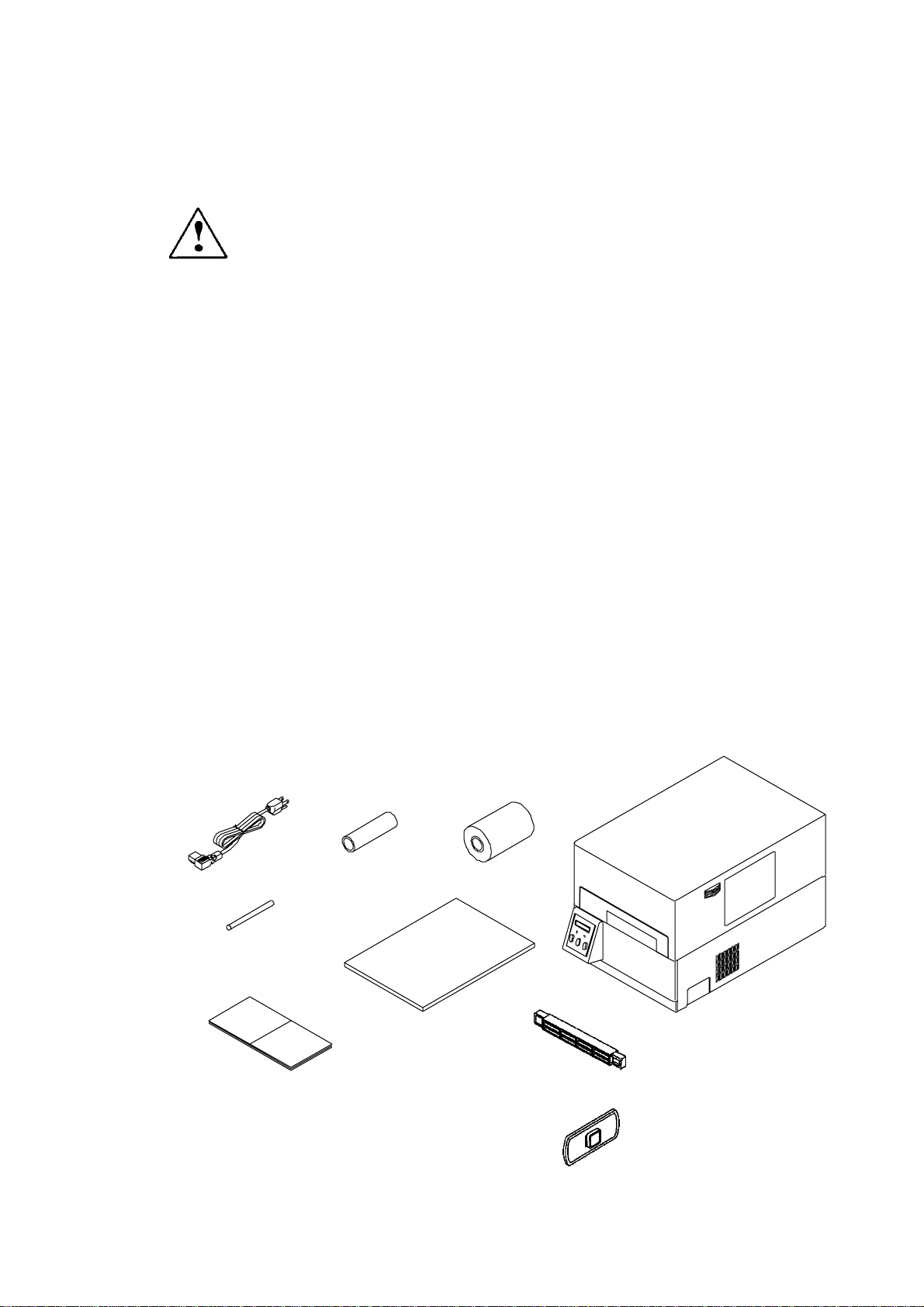
1. 1 Confirmation of Carton Contents
CAUTION Be careful when moving or carrying the prin ter and
when taking the printer out of the carton. The p rinter
may cause inj ury or property damage if dropped. Be
sure to grip the printer housing tightly when taking it
out of the carton. Do not grip th e p rinter b y the foam
packing material which may break, causing the printer
to drop.
Check that the fol lowing accessories are included with the printer in the carton.
· Power cord 1 pc
· Paper core 1 pc
· User's manual (this booklet) 1 copy
· Ink ribbon 1 pc
· Label paper 1 set
· Roll holder 1 pc
· Roll guide 1 pc
· Cleanin g pen 1 pc
Note: The empty carton and packing materials should be stored for future
shipping of the printer.
Power cord
Paper core
Ink ribbon
Cleaning pen
User’s manual
Printer
Label paper
Roll holder
Roll guide
1-2
Page 16
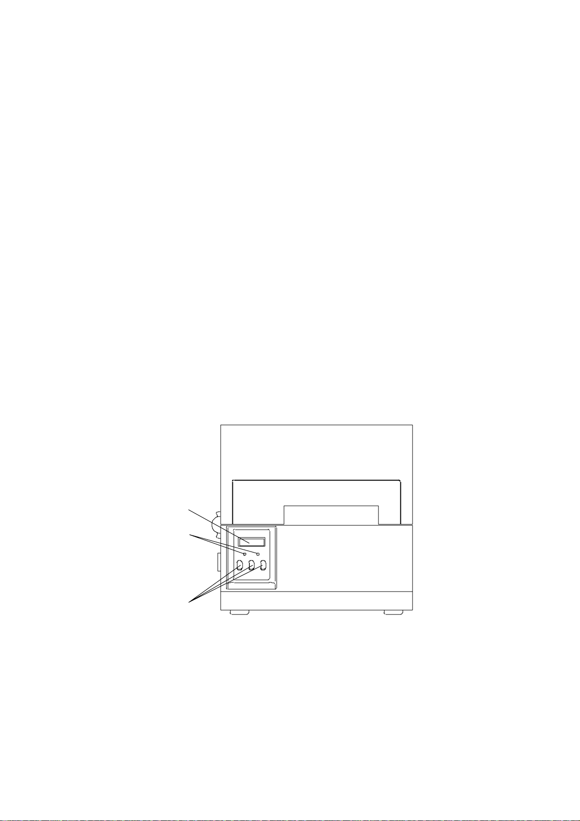
1. 2 Part Names and Functions
D
FRO N T VIEW
n Control panel
The printer has two LED indicator lights and an LCD screen that displays
printer messages.
① LEDs
One LED is the power indicator an d the other is the error indicator.
② LCD
Displays the current printer status, configuration settings, or an
error message.
③ Control keys
The Pause, Feed an d Stop keys are arranged from left to right and
are used to facilitate printer operating. (For details, see Chapter 2
Control Panel.)
① LC
② LEDs
③ Control keys
1-3
Page 17
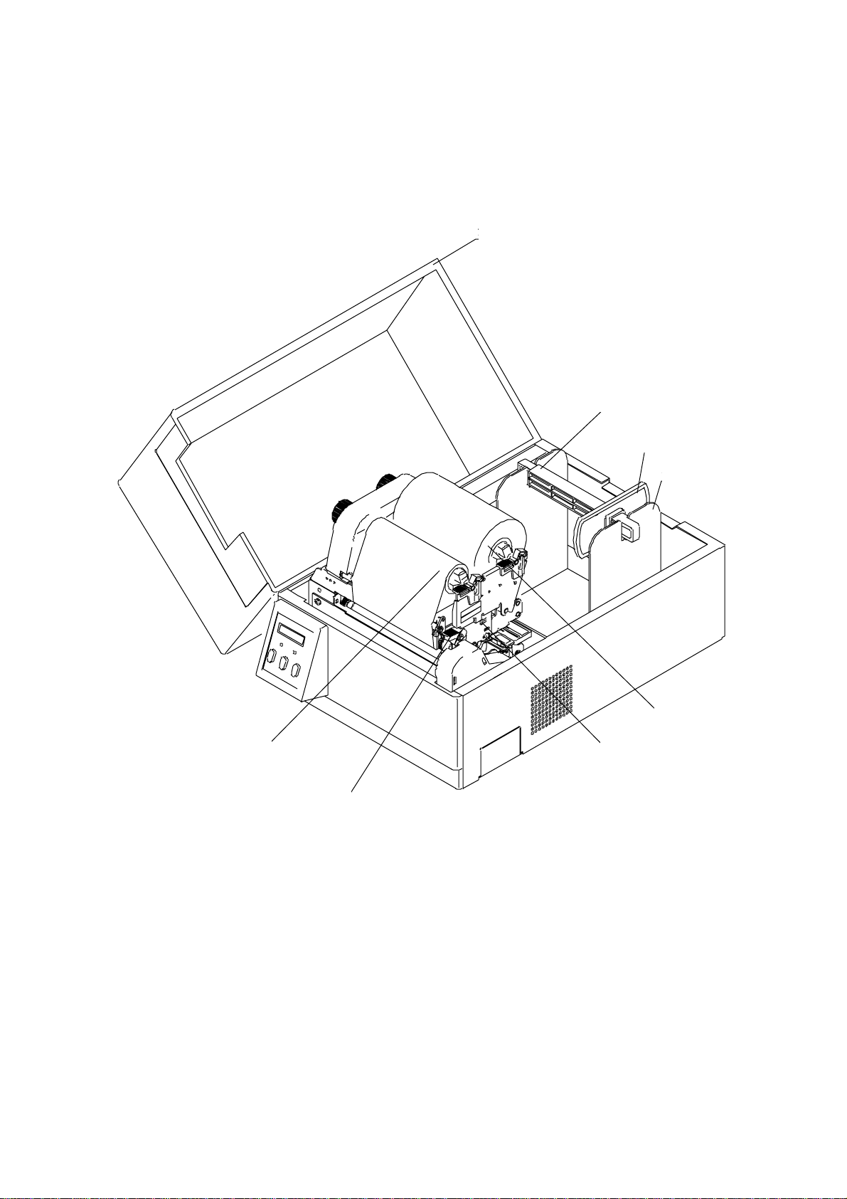
I NSIDE VIEW
① Cover
④ Roll holder
⑤ Roll guide
⑥ Paper holder
② Ribbon holder
③ Ribbon
⑧ Offset verification window
⑦ Open lever
1-4
Page 18

n Names and functions of each part
CAUTION · When opening the cover, open it all the way.
If on ly part way open, the cover could slam shu t,
possibly causing in jury.
· Be careful of th e edge of the cover when the cover
is open ed. It may cau se injury or property
damage.
· Be careful of the edges of the pl ates so injury or
property damage is possible.
① Cover
Opens to allow loading of th e paper and ribbon.
② Ribbon holder
To attach th e ribbon. (See Chapter 3.)
③ Ribbon winder
To win d the ribbon. (See Chapter 3.)
④ Roll holder
Hol ds the roll of paper.
⑤ Roll guide
Guides the roll of paper to be set on the roll holder. The roll guide can be
adjusted in accordance with the width of the paper. (See Chapter 3.)
⑥ Paper holder
Holds the roll holder w hich is inserted in the paper core.
⑦ Open lever
To swing the print head out of the way when loading the paper or cleaning
the print head.
⑧ Offset verification wi ndow
Allows you to check the position of the print head which may need adjustin g
based on the th ick ness of the paper used. (See Chapter 3.)
1-5
Page 19
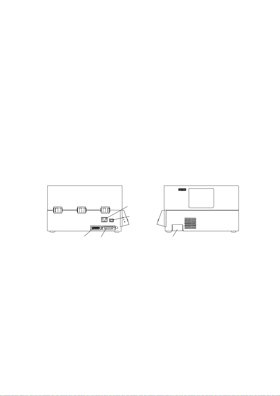
SI DE VIEW
n Interface connectors
To connect the interface cabl e.
n PCMCIA memory card cover
To protect the PCMCIA memory card from exposu re to dust and foreign
matter. To install a PCMCIA memory card, first unhook this cover , then
slide it out.
n Power switch
To turn on/off the power.
n Power inlet
To connect the power cord.
Power
switch
Serial
interface
connector
Parallel
interface
connector
PCMCIA memory card cover
1-6
Page 20
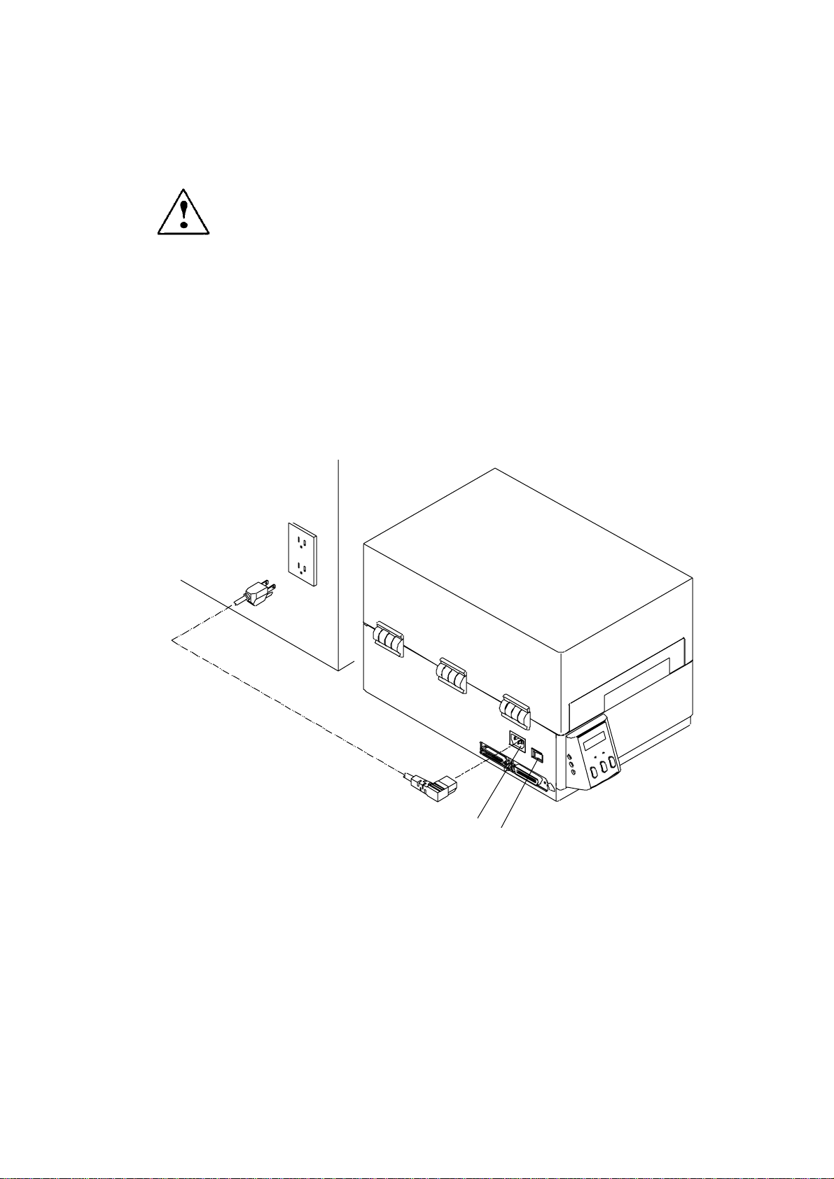
1.3 Connection to Power
A
t
CAUTION Use an AC outlet that accepts a three-pronged plug.
Otherw ise, static electricity may be generated and
there will be danger of electric shock.
Connect to an AC outlet as follows:
1 Check that the power sw itch on the p rinter is set to OFF.
2 Connect the connector of the power cord to the power inlet on th e p rinter.
3 Insert the plug of the power cord in the AC outlet.
C outle
Power
Power switch
1-7
Page 21
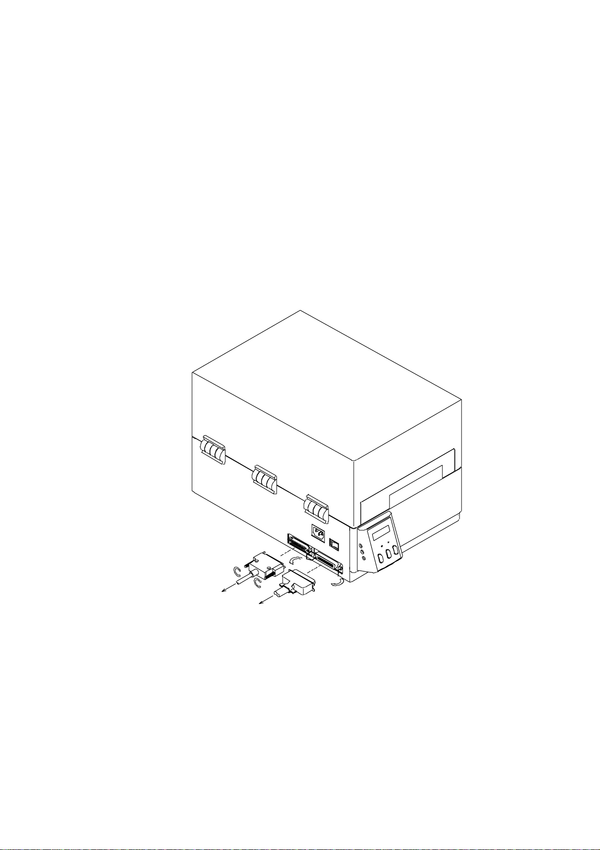
1.4 Connection to a Computer
An interface cable is necessary for connecting the printer to a computer.
To connect them, proceed as follows:
1 Turn off both power switches of the printer and the computer.
2 Connect the connector of one end of the interface cable to th e interface
connector at the lower side of the printer and secure it w ith screws.
3 Connect the connector of the other end of the interface cable to the interface
connector on the computer and secure it with screws.
1-8
Page 22

Chapter 2
Control Panel
2.1 Control Panel 2-2
2.2 LCD/LED Indications and Adjustmen t Controls 2-3
2.3 Normal Operating Mode 2-3
2.4 Printer Setup Mode 2-4
2.5 Self-Test Mode 2-4
2.6 System Maintenance Mode 2-6
2-1
Page 23
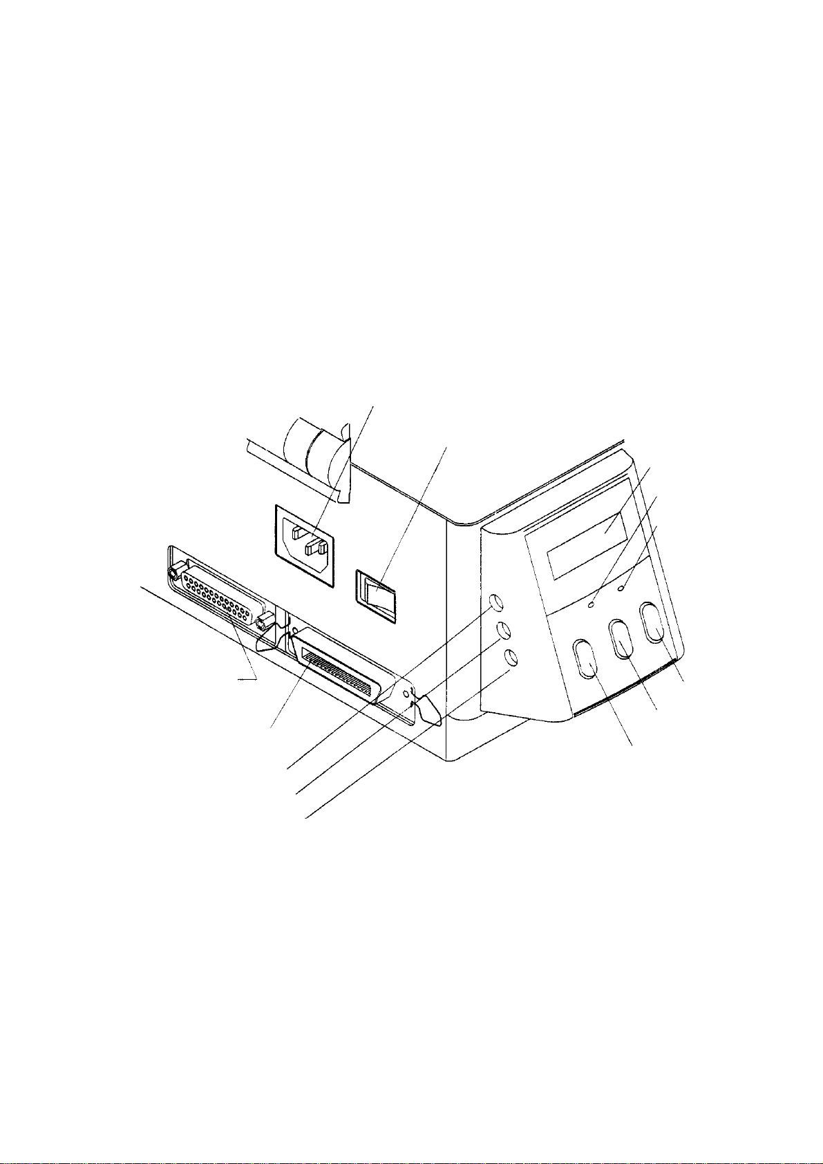
2.1 Control Panel
r
r
C
The control panel, on the front of the printer , con sists of three control keys
(Pause, Feed and Stop), two LED indicator lights (Power, Error), and a LCD
message screen. On the left side of the control panel there are three
adjustment controls (paper gap, black line and LCD contrast).
Exterior view of the control panel
Serial interface connecto
Parallel interface connecto
Paper gap adjustment control
Black line adjustment control
LCD contrast adjustment control
Power inlet
Power switch
D
L
LED power indicator
LED error indicator
Stop key
Feed key
Pause key
2-2
Page 24

2. 2 LCD/LED Indications and Adjustment C ontrols
1 LCD
The eight-ch aracter LCD screen displays the current printer status,
configuration settings, or an error message.
2 LEDs
Power: The green LED power indicator goes on when the power is tuned ON.
Error: The red LED error indicator goes on when an error occurs.
3 Adjustment controls
The three adjustment controls are used to adjust th e paper gap (transparent
type) sensor sensitivity, bl ack line (reflective type) sensor sensitivity, and LCD
contrast.
2.3 Normal Operating Mode
When the power is turned on, the printer enters normal operating mode.
The control keys function as follows:
n Pause key
Temporarily pauses prin ting. "Pause" is displayed on the LCD screen.
If pressed during printing, printin g will stop after the current label is printed.
Press the Pause key again to resume printing.
n Feed key
Advance to the top of the next label. When using continu ous paper,
make su re the Sensor selection is set to ContinuP or a Paper error will
resu lt.
n Stop key
With this key, the operator can stop and can cel the current print job. Pressing
the Stop key during printing stops the printing immediately. Pressing th e Stop
key again cancel s the print job.
2-3
Page 25

2. 4 Printer Setup Mode
To enter the Printer Setup Mode, press and hold down the Pause key then press
the Feed key and release both keys. In a few seconds you will hear a beep and
see Transfer or Dir ectTM displayed on the LCD screen. The functions of the
control keys are described below.
Changes to the prin ter configuration are stored in nonvolatile memory. This
guarantees that the prin ter configuration is maintained even after the power is
turned off.
[Functions]
Print mode selection, peeling sensor ON/OFF, auto-cutter ON/OFF, etc.
n Pause key: Selects the mode.
n Feed key: Selects the mode item.
n Stop key: Saves settings and returns the printer to normal operating mode.
Mode item Indication
¯
¯
¯¯
Direct-thermal/thermal Transfer ® Direct TM ®
transfer printing
¯¯¯¯
Peeling sensor Peel OFF ® Peel ON ®
¯¯¯¯
Auto-cutter Cut OFF® Cut ON ®
¯¯¯¯
Tearing Tear OFF ® T ear ON ®
¯¯¯¯
Sensor selection Edge ® Reflect ® ContinuP ®
2.5 Self-Test Mode
The printer can be placed into self-test mode by pressing and holding the Feed key
while turning the printer on.
Note: Proper use of this mode requires a minimum label size of 4” x 4”. Use of
a smaller label will prevent the user from seeing all printed information,
and verifying the print quality across the entire print head.
2-4
Page 26

During execution of the printer self-test, the prin ter will eject an alignment label,
then print a status report and finall y, print a series of head test patterns. Use the
head test patterns to identify any problems with missing dot rows, uneven head
pressure, heat setting and transfer smearing
.
The status page will look similar to the foll owing:
The Status Label gives the user information regarding the current system setting of
the printer. It references the Version #, shows th e date and time setting, validates
the on board ROM, indicates curren t serial communication values, Mode of printing
(Direct Thermal or Thermal Transfer), the type of media (Gap, Black Line) w ith
sensor voltage values, check s the head and even tells you the number of mm’s of
material that have passed under the head mechanism. All of this information can
be u sefu l when trying to troubleshoot your printer.
When the printer enters Monitor mode, any information communicated to the printer
will be printed on th e label material. After each carriage return a label will be
printed displaying in Hex and ASCII the contents of the data stream received at the
printe r. You can use this to test both the actual fact of communication with the
printer, and the exact contents of the data stream being sent.
T o return the print er to normal opera t ing cycle the power.
2-5
Page 27

2.6 System Maintenance Mode
To enter the printer’s maintenance mode, press and hold th e Pause, Feed and
Stop keys simultan eously while turning on the printer’s power. In a few
seconds you will hear a beep and see S Mainte displ ayed on the LCD screen.
Note: To reset al l values to defaul t settings, con tinue to hold these keys for
an additional four (4) seconds, until you hear a second beep an d see
S/I Init displayed on the screen. See the chart at the end of this
section for the prin ters default val ues.
After entering this mode the printer will display the first of several parameters
for you to set. Select each parameter (Mode) by pressing the Pause key, and
make changes to that selection by pressing the Feed key to cycle through the
available choices.
Pressin g th e Stop key will save your se ttings and return th e printer to normal
operating mode. After you press the Stop key, the printer will display RESET
in the LCD screen and, a few seconds later , On Line.
Note: Do not tur n off the printer until you see ‘On Line’ in the display, or
your changes may be lost.
Mode item Indication
¯
¯
¯¯
Baud rate 9600bps ® 19200bps ® ¼¼¼ ® 4800bps ®
¯¯¯¯
Data length 8 bits ® 7 bits ®
¯¯¯¯
Native NativeON® NativeOF ®
¯¯¯¯
Adjustable sensor AJSensOF ® AJSe n sO N ®
¯¯¯¯
Voltage setting PE#.##V ® BL#.##V®
2-6
Page 28

The final display in the maintenance mode is the Voltage setting mode. The
display will show ‘PE #.##V’ and as the second option ‘BL #.##V’ for Gap
mode and Black line mode. Th e ‘#.##’ represents the current voltage
reading for these sensors. For proper operation of the printer in these
modes the voltage needs to be set to a specific range of values for the
currently installed media.
Note: A small, flat blade, jewel ers screwdriver will be needed to make the
following adjustments.
To set the Paper- Gap vol tage;
1) Peel off a label from the media to expose the liner.
2) Place the material in to the printer so the exposed liner is under the sensor
guide (#3 on the illustration on page 3-7) and close the sensor guide.
3) Close the printer cover to prevent ambient l ight from skewing the readings.
4) Adjust the Paper Gap sensor (the top hol e on the front left-hand side of th e
printer (see illustration on page 2-2)) to read between 3.00V to 3.30V.
5) Open the printer cover and draw the media under the sensor guide, un til a
label is positioned under the sensor, close the cover .
6) The reading shoul d be less th an the reading voltage of Step 4. The difference
between the two should be more than 1.00V.
To set the Black Line voltage;
1) Place label material under the sensor guide with the media positioned so that
the b lack line is not at the sen sor.
2) Close the printer cover to prevent ambient l ight from skewing the readings.
3) Adjust the Black Line sensor (the middle hole on the front left-hand side of the
printer (see illustration on page 2-2)) to read between 3.00V to 3.30V.
4) Open the printer cover and draw the media under the sensor guide, un til a the
Black Line is positioned under the sensor, close the cover.
5) The reading shoul d be less th an the reading voltage of Step 3. The difference
between the two should be more than 1.00V.
2-7
Page 29

Printer Default Val u es
Baud Rate: 9600
RS-232C setting
Data Length : 8 bit
Print Mode Setting Thermal Transfer
Peeling: OFF
Optional F unctions
Paper Sensor Setting Edge
Adjustable sensor AJSensOF
Model Native ON
Auto-cutter: OFF
Tear-off: OFF
2-8
Page 30

Chapter 3
Preparati on f or
Printing
3.1 Kinds of Paper 3-2
3.2 Specification of Label and Tag 3-2
3.3 Paper Setting 3-6
3.4 Ribbon 3-8
3.5 Ribbon Setting 3-9
3.6 Head Offset Adjustments 3-10
3.7 Head Pressure Adjustments 3-1 1
3.8 Ribbon Tension Adjustments 3-12
3.9 Adjustable Sensor 3-13
3.9.1 Ex terior view and part names 3-13
3.9.2 How to operate adjustabl e sensor 3-14
3.9.3 Specification of paper
(for adjustable sensor) 3-15
3.10 Cleaning 3-16
3-1
Page 31

3. 1 Kinds of Paper
1 Kinds of Paper
The printer is capable of printing on direct-thermal or thermal-transfer
paper. The paper must be high-qu ality. Otherw ise, good print quality
and extended print head life can not be guaranteed.
2 Type of paper
· Label (con tinuous, die-cut, fanfold)
· Tag
· Ticket
Both in-wound and out-wound paper rolls may be used.
3 Size of paper
Paper width: 25.4 mm-118 mm (1 in-4.65 in)
Paper thickn ess: 0.063 mm-0.254 mm (0.0025 in-0.01 in)
Max. printing width: 104 mm (4.1 in)
Max. printing length: 406 mm (16 in)
Max. outer diameter of roll paper: 203 mm (8 in )
Paper core inner diameter: 38 mm-76 mm (1.5 in-3 in)
3. 2 Specification of Label and Tag
The position of a label or tags is detected by the printer's transparent-type
and reflective-type photosensors.
Transparent-type photosensor: Detects paper gap between label s
and tag notch.
Reflective-type photosen sor: Detects black line.
n Specification of paper
3-2
Page 32

Minimum value mm (in) Ma ximum value mm (in)
A Label width 7.62 (0.3) 118.00 (4.65)
B Liner width 25.40 (1.0) 118.00 (4.65)
C Label left-side edge position 0 2.54 (0.10)
D Label paper-gap length 2.54 (0.10) 2539.00 (99.96)
E Label length 2.54 (0.10) 2539.00 (99.96)
F Label pitch 5.08 (0.20) 2539.00 (99.96)
G Liner thickness 0.06 (0.0025) 0.125 (0.0049)
H Paper thickness 0.06 (0.0025) 0.25 (0.01)
I Notch right-side edge position 8.3 (0.32) 11 (0.43)
J Notch left-side edge position 0 4.7 (0.19)
K Notch length 2.54 (0.10) 17.80 (0.70)
L Black line right-side edge position 15.00 (0. 59) ¾
M Black line left-side edge position 0 1.5 (0.06)
N Black line width 3.18 (0.125) 17.80 (0.70)
Note: · I f paper has both label paper-gap and black-line, choose the paper-gap sensor.
· Fanfold uses the paper-gap sensor.
Size of paper
C
H
G
F D E
Label Continuous paper
B
Notch detection Black-line detection
A
I
L
M
I
J
K K
N
Black-lin e (back)
OD value: 1.5 or
more
Ink containing
carbon
Printing
area
Printing ar ea
Use of paper-gap sensor Use of paper-gap sensor Use of black-line sensor
Direction of paper feed
2.5mm 105.7mm (9.8mm)
Left-side
margin
Printing area Right-side
margin
3-3
Page 33

Units for position and l ength
The print positions may be specified in either inch or metric system.
Switching between the two systems is accomplished through software.
The print positions can be freely designated within the maximum label size,
regardless of which system you use.
n Inch system
Basic unit (point): 0.01 in (0.254 mm)
The position of each row address (in the direction of main scanning) and
column address (in the direction of subscanning) is designated in 0.01-inch
units. In the case of the 400 dpi head, if the print position changes by 1 point,
it will change by 2 dots.
1 point = 0.01 in = 4 dots
100 point = 1.00 in = 400
.
.
.
.
dots
n Metric system
Basic u nit (point): 0.1 mm
The position of each row address and column address is designated in
0.1-mm units. Since there is a slight difference between the main and
subscanning density and the point value, the nearest dot number to the
designated address is selected in one dot (0.125 mm) un its.
.
1 point = 0.1 mm = 2 dot
100 point = 10.0 mm = 157
.
.
.
dots
The basic unit is common to all label format and system-level commands.
The label format commands are used to specify the position, length,
whol e-screen offset, etc. The system-level commands are use d to
specify the maximum paper length, home-position offset, etc.
3-4
Page 34

Reference line and points
g
The reference line and points are described here. The position of 2.5
mm from the left edge of the paper is the reference line for paper.
Always the left bottom is the reference point for printing ch aracters and
bar codes. The concept of this referen ce line and points are common to
such commands as ru led line and graphics.
Left edge of paper
Paper reference line
Printing reference point
Printing reference point
2.5
Direction of paper feed
Printin
reference point
Printing reference point
3-5
Page 35

3.3 Paper Setting
CAUTION Be careful of the edges of the pl ates so injury or
The printer is designed for easy loading of paper and ribbon. After opening th e
cover, set the register paper as follows:
1 Push down the open lever ① to lift the prin t head up.
2 Push down the open guide lever ③ to lift the sensor arm ② up.
3 Attach the roll paper and roll gu ide ⑤ to the roll holder ④ and position it in the
paper holder ⑥. After installing the roll paper, adjust the roll guide ⑤ to the
width of the roll paper. The roll paper should be in its deepest position
(reference plane).
4 If necessary, move the paper guide ⑦ out to allow for paper insertion.
5 Set the roll paper as shown in the figure.
6 The left side of roll paper shoul d be flush against th e fixed paper guide ⑧.
Adjust the movable paper guide ⑦ to slightly contact the other end of the roll
so that the paper does not sk ew.
property damage is possible.
7 Push down the media guide ② until the lever ③ is hooked.
8 Align the paper with the positioning notch of the tear-off plate ⑨ and then
press down the blue tab ⑩ to close the printer me c hanis m. Press it until it
clicks to ensure proper closure.
9 Cl ose the prin ter cover.
10 Turn on the power to the printer. The LCD screen on the control panel will
display "On line." Press the Feed key. The paper will advance to the next
label and stop.
(For circled numbers, see figure on next page.)
3-6
Page 36

paper
①
⑩
②
Roll
⑤
⑩
①
Reference
plane
③
Roll paper
⑥
④
⑤
④
⑥
⑧
3-7
Notch for alignment
③
⑦
⑨
Page 37

3.4 Ribbon
1. Kinds of ribbon
This printer uses a melt in k ribbon.
1) Wax: multipurpose ribbon.
2) Wax resin: multipurpose higher-quality ribbon.
3) Resin: special ribbon with weather resistance. When using resin
ribbon, print speed must be slower an d the printing energy must be
greater.
2. Type of ribbon
Both in-wound and out-wound ribbons can be used.
3. Size of ribbon
Width of ribbon: 25.4 mm-114.3 mm (1 in -4.5 in)
The width of the ribbon is recommended to be the ±10% of the width of the
paper used.
Max. length: 360 m
Max. outer diameter: 70 mm
Paper core inner diameter: 25.4 mm (1 in) ±0.4 mm
With a single roll of the ribbon (360 m), about two rolls of the paper w ith outer
diameter of 203 mm (8 in) can be used for printing.
3-8
Page 38

3.5 Ribbon Setting
bbo
r
CAUTION Be careful of the edges of the pl ates so injury or
property damage does not occur.
After opening the cover, install the ribbon as follows:
1 Push down the open lever ① to lift the print head up.
2 Insert the ribbon in the ribbon shaft ⑪ until it is in its deepest position. Then
set the ribbon holder as shown in the figure.
3 Insert the ribbon shaft ⑫ in the paper core ⑬ until it is in its deepest position.
Then set the ribbon winder as shown in the figure.
4 Adhere the top end of the ribbon to the paper core with adhesive tape. Turn
the ribbon winder in the direction of ribbon winding to remove slackness and
wrinkles from the ribbon.
5 Press down the ribbon bearing flat ⑩ to close the printer mechanism.
Press it until it clicks.
6 Cl ose the prin ter cover.
7 Turn on the power to the printer. The LCD screen on the control panel will
display "On line." Press the Feed key. The paper will advance to the next
label and stop there.
⑫
Direction of ribbon winding
①
⑪
Ribbon
⑬
Print head opened
Roll pape
Ri
n
Completion of setting paper and ribbon
Thermal transfer frame
3-9
Page 39

3.6 Head Offset Adjustments
CAUTION Ensure the print head offset adjustments are made
properly according to the type of print media (thickness &
width). Incorrect adjustm e nts can cause failure of the
print head.
The printer has already been factory-set to the proper print quality when using
the recommended label paper. If the print quality is inferior because of the
paper, adjust it according to the following:
1 For standard label paper and thermal paper:
a) Look through the offset verification window . Set it to the center lin e
(middle of three lin es) by turning the offset adjustment screw with a
screwdriver.
b) Turn the offset adjustment screw countercl ockw ise two turns.
2 For tag stock:
a) Look through the offset verification window . Set it to the bottom line
position by turning the offset adjustment screw with a screwdriver.
Offset adjustment screw (M3)
Offset verification window
The relationship between the offset adj ustment screw and the print head
heating element is shown below:
a) Print head position for label
Heating element
Offset adjustment screw
Offset verification window
a
b) Print head position for tag
Offset adjustment
screw
Offset verification window
3-10
Page 40

Heating element
b
3-11
Page 41

3.7 Head Pressure Adjustments
The printer has already been factory-set with the label width of 118 mm. When
usin g paper with a different width, adjust the head pressure in the following way:
a) Look through the verification window on the upper frame, adjust the mark to
the value in mm that represents the width of the label by turning the head
pressure adjustment screw.
b) Make further adjustments after sampling the prin t image.
(1) When the print on the right side is too light:
Turn the head pressu re adjustment screw clockwise to move the mark
(white) to the right.
(2) When the p rint on the left side is too light:
Turn the head pressu re adjustment screw counterclockwise to move the
mark (white) to the left.
These adjustments are u seful for preventing ribbon wrinkle and paper sk ewing.
For more details, consul t our service person nel.
Verification Paper width
25.4 mm
(1 inch)
50.8 mm
(2 inch)
76.2 mm
(3 inch)
Upper f r am e
window
Head
pressure
adjustment
screw
Note: These v al ues are jus t f or cr it er ia.
101.6 mm
(4 inch)
Used for adjustment
wh en ribbon wr in kles or
skews w it h paper width
of 4 inches
Factory sett in g
3-12
Page 42

3.8 Ribbon Tension Adjustments
When the ribbon slips or wrinkles during printing, adjust the ribbon tension. The
printer h as already been factory set with the ribbon width of 114 mm. When using
ribbon with a different width, adjust it according to the following procedure:
a) Hold th e ribbon roll with one hand so that it does not turn.
b) Slightly push the knob toward the ribbon roll with the other hand an d rotate the
knob until the stopper comes to the desired position.
c) Gradually release the knob so that the stopper fits in the groove on the knob.
Set values to each ribbon width :
Ribbon width
Adjustment when r ibbon slips 5 5 Mild
25.4 mm (1 in) 4 4
50.8 mm (2 in) 3 3
76.2 mm (3 in) 2 2
101.6 mm (4 in): f actory sett ing 1 1 Strong
Ribbon winding
section
Ribbon feed
section
Tension
d) After printing, che ck for ribbon wrinkle or slipping. If it occurs, adjust it further
according to the following procedure:
(1) When the ribbon wrinkles, the ten sion on th e ribbon winding section
shoul d be increased.
(2) When the ribbon slips, the tension on the ribbon feed section should be
decreased. If the problem is not resolved even when the tension on
the ribbon feed section is set to 3, the tension on the ribbon w inding
section should be in creased.
If ribbon problems are not resolved, consult our service person nel.
Variable knob
Ribbon feed section
Ribbon winding section
Mild
Strong
Strong
Mild
3-13
Page 43

3.9 Adjustable Sensor
3.9. 1 Exteri or view and part names
Adjust-knob
192.4
Mark (Yellow) Guide rail upper
37.7 70.6
Exterior view and part names
3-14
Page 44

3.9. 2 How t o operat e adjustable sensor
(1) Move the adj ustable sensor unit to your required position by turning the
adjust-knob. First measure the position to detect, then align the mark of the
measure on the guide rail upper with the sensor position mark (yellow) on the
upper sensor to set to the position to detect.
The sensor movable range is sh own below.
(2) Load the liner and close the guide rail upper and set voltage to 3V.
For voltage setting, see the chapter on Control Panel.
Left- side edge of paper
0 mm
118 m m ( m ax. width of paper )
59 mm (s ensor movabl e r ange)
Sensor movable range
3-15
Page 45

3.9. 3 Specification o f paper (for adjustable sensor)
Minimum value mm (in) Ma ximum value mm (in)
A Label width 25.40 (1.0) 118.00 (4.65)
B Liner width 25.40 (1.0) 118.00 (4.65)
C Label left-side edge position 0 2.54 (0.10)
D Label paper-gap length 2.54 (0.10) 2539.00 (99.96)
E Label length 12.70 (0.50) 2539.00 (99.96)
F Label pitch 12.70 (0.50) 2539.00 (99.96)
G Liner thickness 0.06 (0.0025) 0.125 (0.0049)
H Paper thickness 0.06 (0.0025) 0.25 (0.01)
I Notch right-side edge position 3.6 (0.14) 60.8 (2.39)
J Notch left-side edge position 0 57.2 (2.25)
K Notch length 2.54 (0.10) 17.80 (0.70)
L Black line right-side edge position 15.00 (0. 59) 66.5 (2.62)
M Black line left-side edge position 0 51.5 (2.02)
N Black line width 3.18 (0.125) 17.80 (0.70)
Note: · I f paper has both label paper-gap and black-line, choose the paper-gap sensor.
· Fanfold uses the paper-gap sensor.
Size of paper
C
H
G
F D E
Label Continuous paper
B
Notch detection Black-line detection
A
I
L
M
I
J
K K
N
Black-lin e (back)
OD value: 1.5 or
more
Ink containing
carbon
Printing
area
Printing ar ea
Use of paper-gap sensor Use of paper-gap sensor Use of black-line sensor
Direction of paper feed
2.5mm 104.0mm (11.5mm)
Left-side
margin
Printing area Right-side
margin
3-16
Page 46

3.10 Cleaning
Wipe off any foreign matter such as dust, ribbon residue, and adhesive substance
stuck to the thermal head, ribbon guide roller, and platen with a soft cloth soaked
in ethyl alcohol. Periodic cleaning of the thermal print head is essential to
guarantee quality printing and extended print head life.
Do not use solvent such as benzene and thinner that will dissol ve the plastic.
Ribbon guide roller
Ribbon guide roller
Thermal head
Platen roller
3-17
Page 47

Chapter 4
Troubleshooting
4.1 Error Messages 4-2
4.1.1 Error descriptions and indications 4-2
4.1.2 Error indications and corrective actions 4-4
4.2 Power Troubleshooting 4-7
4.3 Paper Feed Troubleshooting 4-8
4.4 Ribbon Feed Troubleshooting 4-9
4.5 Print Troubleshooting 4-10
4.6 Interface Troubleshooting 4-11
4-1
Page 48

4.1 Error Messages
When there is a problem with the printer:
- A buzzer sounds
- Th e error indicator lights up
- An error message is displayed on the LCD screen
Error descriptions and corrective actions are shown below.
4.1. 1 Error descript ions an d indicati ons
Description Indication LED Buzzer
Batter y dead ( f or c lock and backup RAM) Battery Lights Sound s long
Low head temperature ColdHead Lights Sounds long
Low PCB temperature Cold PCB Lights So unds l ong
Abnormal head resistance value
Error contents and head information
repeatedly displayed
Rank: Rank of head resistance value
Average: Average of resistance values
(A/D reading value decimal
system)
Maximum: Max. value of r esistance
Minimum: Min. value of resistance
Communicat ion error (receive buffer overrun) OverFlow Lights Sound s long
Communicat ion error ( par ity, f r aming) S/I Err Lights Sound s long
Communicat ion error (transmit buffer overflow) HostBusy
Pause key pressed Pause - - - -
Pause comma nd r eception ( re m ot e cont ro l ) Pause - - - -
Head overheat OverHeat
Stop key pressed Stop - - Sounds short
St op comm and re cept ion (r emo te control ) Cancel - - - -
Mechanism head open HeadOpen Lights Sounds short
Paper end (no paper left) PaperEnd Lights Sounds short
Head Err
Rank ***
Ave.***
Max.***
Min. ***
T .D.Full
Cooling
Lights Sound s long
Blinks Sounds short
3 times
Blinks Sounds short
3 times
3 times
3 times
3 times
4-2
Page 49

Description Indication LED Buzzer
Paper out (paper position can't be detected)
Error contents and sensor inf or mation
repeatedly displayed
M command: Sets length for detection
miss checking with system
comma nd M
M a ximum: Max. val ue of senso r
reading volt age
M i nimum: Min. va l ue of s ensor
reading volt age
Ribbon end RibonOut Lights Sounds short
PCB overheat
(PCB or sensor abnormality)
Fan stop Fan stop Blinks Sounds short
Option board abnormality OP Err Light s Sounds shor t
Auto-cutter abnormality (such as poor
engagement)
ROM checksum error ROM Err Lights S ounds lo ng
RAM check error RAM Err Ligh ts Sounds lo ng
PaperErr
M CMND
Max*.**V
Min*. **V
OverHeat Ligh ts Sounds short
Cut Err Lights Sounds short
Lights Sounds short
3 times
3 times
3 times
3 times
3 times
3 times
4-3
Page 50

4.1. 2 Error indications and corrective actions
Indication Description Corrective actions
Battery Batter y dead Automatically returned after displaying the error
for a certain time.
Change the lithium battery (CR2032).
Note: Contact our service personnel to replace
the battery.
If the battery runs down, the r ea ltime clock will
sto p a nd t he co nte nts o f the memor y s witch w ill
be lost.
ColdHead Low head temperature Automatically returned after displaying the error
for a certain time.
Raise the temperature around t he printer.
Print density becomes low and print quality
becomes inferior w hen the head temperature
is low.
Cold PCB Low PCB temperature Automatically returned after displaying the error
for a certain time.
Raise the temperature around t he printer.
Print density becomes low and print quality
becomes inferior w hen the head temperature
is low.
Head Err Abnor mal head
resistance value
OverFlow Communication error
(receive buffer
overrun)
S/I Err Communicat ion error
(parity, f r aming)
HostBusy
T .D.Full
Pause Pause key pr ess ed Press t he Pause key once again to resume
Communicat ion error
(transmit buffer
overflow)
Check the contents and clear with the St op k ey.
Replace the print head.
Print quality is affect ed at the section where the
head resistance value is abnormal.
Check the contents and clear with the St op k ey.
Correct the communication control system or
communication cable failure.
Check the contents and clear with the St op k ey.
Correct the communication parameter or
communication cable failure.
Automatically returned if the computer receives
data and the buf fer becomes empty.
printing.
If t he Stop key is pressed, t he stored pr inting
content s will be los t and "on line" will t urn on.
Pause Pa use com m and
reception
(communication
control)
Same as above.
4-4
Page 51

Indication Description Corrective actions
OverHeat
Cooling
Stop Stop key pressed Enters a pause after displaying the stop by the
Cancel Stop command
HeadOpen Mechanism head
PaperEnd Paper end (no paper
PaperErr Paper out (paper
Head overheat Wait unt il the head temperature goes down.
When the temperature becomes low, the
remaining print ing r e s umes.
Stop key.
If the Pause key is p r e s s e d, the pr int ing w ill
resume.
If t he Stop key is pressed again, the stored
printing c ont e nts will be los t and "on line" will
turn on.
Displays the stop by the stop command,
reception
(communication
control)
open
left)
position can' t be
detected)
discards the stored pr inting contents, and
enters a pause.
If the Pause key is p r e s s e d, "on line" will turn
on.
Close the mechanism head.
Install the paper.
Check the contents and clear with the St op
key.
Correct the faulty setting of the paper detection
(paper gap, black line, continuous paper).
Correct the faulty parameter f or paper ( max.
le ngt h, continuous paper) .
Adjust the sensor or change for t he paper that
accepts t he paper position detection.
Specify the length for det ect ion miss checking
with the M command.
When the paper position c an't be det ect ed
during paper f eeding by the specified length, it
is judged error. G enerally specify the length
about three times the label length.
In case of the continuous paper, specify the
label lengt h with the C command.
Difference betw een the maximum and
minimum values of the sensor reading voltage
must be 0.8 V or more.
Sensor adjust ments and paper characteristic
verification (voltage verification) can be
performed with the Maintenance mode.
4-5
Page 52

Indication Description Correc tive act ions
RibonOut Ribbon end Check the contents and clear with the St op
key.
Install the ribbon.
Check that the ribbon winds fully.
Correct the faulty setting of the print mode
(direct-thermal or thermal-transfer).
OverHeat PCB overheat Turn off the power and reset the printer. If
this recurs, contact our service personnel.
Fan stop Fan stop Check for the fan stop caused by the problems
such as foreign matter entered in the air vent.
Automatically returned if the fan turns again.
If disassembling is needed t o r emove foreign
matter or t he problem can't be identified,
contact our service personnel.
OP Err Option board
abnormal ity
Cut Err Auto-cutter
abnormality (such as
poor engagement )
ROM Err ROM checksum error Turn off the power and reset the print er. If
RAM Err RAM checksum error Turn off the power and reset the print er. If
- - System error (such as
timer or CPU
malfunction)
Turn off the power and reset the printer. If
this recurs, contact our service personnel.
Check the contents and clear with the St op
key.
If t his can't be cleared, t urn off the power and
remove foreign matter from the auto-cutter.
If this recurs, contact our service personnel.
this recurs, contact our service personnel.
this recurs, contact our service personnel.
First protect t he system, then reset t he printer.
4-6
Page 53

4.2 Power Troubleshooting
Problem Cause and remedy
No power even
with power switch
turned ON.
• Power cord is not
properly connected to the
outlet.
• Power cord is not
properly connected to the
power inlet.
• I nput voltage is not
correct ; input voltage is
greater or less t han the
rated voltage.
• Corr ec t RS-232C cable is
not us ed.
® Turn off t he power switch and
properly reconnect the power
cord to the outlet.
® Turn off t he power switch and
properly reconnect the power
cord to the power inlet.
® Set input voltage within the rated
voltage (punct ure voltage may
occur. Contact our service
personnel).
® Turn off t he power switch and
unplug the int er f ace c able.
Check that power is pr ovided by
turning on the power swit ch and
then use the correct RS-232C
cable.
4-7
Page 54

4. 3 Paper Feed Troubleshooting
Problem Cause and remedy
Paper doesn't
feed.
Paper skew. ・ Paper end is not in
Paper doesn't
align w ith the print
position.
・ Wr ong paper path.
・ M echanism head is open.
contact with the paper
guide.
・ Roll g uide is not in
contact with the roll
paper.
・ Head pressure is not
correct.
・ Set t ing mode is not
correct.
・ Paper gap ( black line)
sensor adjustment failure.
・ Transfer data is abnormal.
® Use correct pat h.
® Close the mechanism head.
® Slightly push the paper guide
against the paper end.
® Slig htly p ush the r o ll guide
against the roll paper.
® Adjust it with the offset adjustment
screw accor ding to the paper
width.
® Check whether the setting mode
is for paper gap or black line
sensor and if it is not, change it as
necessary.
® Adjust the voltage of t he paper
gap and black line sensor f r om
the voltage sett ing in the system
maint enance mode.
® If the contents of the transfer data
are incorrect, set them pr oper ly
again.
4-8
Page 55

4. 4 Ribbon Feed Troubleshooting
Problem Cause and remedy
Ribbon doesn't
wind.
Ribbon wrinkles. ・ Tension of ribbon holder
・ Print mode is set to
direct-thermal printing.
・ Wr ong ribbon path.
・ Ribbon wind direction is
reversed.
・ Ribbon wind tens ion is
not correct.
and ribbon winder is not
correct.
・ Print density (heating
factor) is not correct.
・ Angle of ribbon guide bar
is not correct.
・ Ribbon and paper are not
proper.
® Change to the thermal-transfer
printing.
® Use correct pat h.
® Set it pr oper ly.
® Set it pr oper ly.
® Set it pr oper ly.
® Correct the parameter of the Hnn
command with the printing
contents definition mode.
® Contact our service personnel to
adjust the ribbon guide bar.
® Contact our service personnel.
Note: I f narrow paper is used, the ribbon may wrinkle. Decrease
the right-side head pressure by turning t he offs et adjustment screw t o
prevent the ribbon from wrinkling.
4-9
Page 56

4.5 Print Troubleshooting
Problem Cause and remedy
Printing doesn't
start.
Missing lines. ・ Pr int head connector
Dropouts. ・ Print head is dirty.
・ Power to the printer is off.
・ Printer is not properly
connected to computer.
・ Printer setting is not
correct.
connect ion failure.
・ Platen is dirty.
® Turn the power switch to ON.
If p o wer s till doesn't turn on,
follo w ste p s in Section 4.2
Power Troubleshoot ing.
® Turn the power switch to OFF and
connect it properly.
® Correct the printer setting.
® If the print head connector is not
properly connected, insert it
correctly.
® Check the print head
heat-generation body for dirt. I f
it's dirt y, wipe t he surface of t he
print head heat- generation body
with a soft cloth soaked in
ethylalcohol et c.
® Remove dirt or label or tape
scraps st uck to t he platen.
Note: If t hose can't be removed,
contact our service personnel for
maintenance.
Print is too light o r
dark.
Other printing
abnormal ities
・ I nk ribbon and paper are
not the recommended
type.
・ Paper quality doesn't
match the print head
offset.
・ Paper width doesn' t
match the print head
pressure.
・ Printer set up mode is not
correct.
・ Set t ing of printing energy
level is not c o r rect .
・ Check the error message on the control panel and correct it
according to the descriptions on Sect ion 2) Error s and corr ect ive
actions, 4.1 Err or M essages.
® Change to the recommended
type after checking the ink
ribbon and paper maker and
identification number.
® Adjust the offset. See Section
3.6 Print Head Offset
Adjustments.
® Adjust the print head pressure.
See Section 3.7 Print Head
Pressure A dj ustme nts.
® Check whether the setting mode
is for direct-thermal or
thermal-transfer printing and if it is
not, change it as necessary.
® Check the setting value of printing
energy level and adjust it as
necessary.
4-10
Page 57

4-11
Page 58

4.6 Interface Troubleshooting
Problem Cause and remedy
Printer doesn't
print.
Print disordered.
Error message is
displayed and
printer doesn't
print.
The following are the probable causes:
・ I nterf ac e cable is not
properly connected.
・ I nterf ac e cable is not the
standard type.
・ Communication
parameter set t ing is not
correct.
® Check that the interface cable
® Replace it.
® Set t he system maintenance
is connect ed pr oper ly.
mode from the control panel and
check/correct the communication
parameter value.
4-12
Page 59

4-13
Page 60

Chapter 5
Options
Factory or Reseller (Deale r) Option s:
5.1 Auto-Cutter Unit 5-2
5.2 Peeler Unit 5-2
User Options:
5.3 PCMCIA Memory Card 5-3
5-1
Page 61

5.1 Auto-Cutter Unit
The cutter mechanism is a rotary cu tter designed to handle paper, labels, ticket and
tag stock. It has an extremel y durable mechan ism designed for in excess of
1,000,000 cuts. See the Cutter User’s Manual for details.
n Specifications
・ Cutting method: Rotary cutter
・ Max. thickness of cut paper: 0.01 in (0.254 mm)
・ Min. length of cut paper: 1 in (25.4 mm)
5.2 Peeler Unit
The peeler unit is designed to automatically strip the label from the liner. See th e
Peeler User’s Manual for details.
n Specifications
・ Width of paper: 1-4.65 in (25.4-118 mm)
・ Max. diameter for roll paper: 8 in (203 mm)
・ Inner diameter for roll paper: 3 in (76 mm) or more
・ Min. length of label: 1 in (25.4 mm)
・ Thickness of paper: 0.0067 in (0.17 mm), max .
・ Thickness of liner: 0.0027 in (0.07 mm), max.
・ Unusable paper: Special paper (Whitepet, etc.) or too
flexible paper causing jams
5-2
Page 62

5.3 PCMCIA Memory Card
The PCMCIA memory card is used to:
1 Store print format files. Data in the field register area can be stored and
loaded.
2 Store graphic data. For example, graphic data such as a corporate logo can
be stored and recalled from the PCMCIA memory card an d printed.
3 Store downloaded HP Soft fon ts.
n Installation
1 Turn off the power to the printer.
2 Remove the PCMCIA memory card cover at the bottom of the printer (see
figu re).
3 Insert the memory card (make sure the card is not inverted).
4 Repl ace the PCMCIA memory card cover.
Notes: ・ Before use, carefully read and understand the instructions
・ Never try to in se r t or remove the PCMCIA m e mory card before the
・ Always close the PCMCIA memory card cover to keep out dirt.
・ If the PCMCIA me mory card write failu re occurs, check it w ith the
Note description facing up
regarding the PCMCIA memory card.
power to the printer is turn e d off.
test command (STX.w).
5-3
Page 63

5-4
Page 64

Chapter 6
Specifications
6.1 Main Specifications 6-2
6.2 Interface 6-6
6.2.1 System configuration 6-6
6.2.2 Specification of interface 6-7
6.2.3 RS-232C loopback test 6-8
6.2.4 RS-232C protocol 6-9
6.2.5 Interface pin assignment 6-11
6.3 Outline of Command System 6-13
6.4 Example of Connection to a Computer 6-14
6.5 Tear-Off Function 6-15
6.5.1 Turning Tear ON/OFF 6-15
6.5.2 Tear-off when printing 6-15
6.5.3 Tear-off when feeding 6-16
6.5.4 Tear-off and type of data 6-17
6.5.5 Cut position adju stments 6-17
6.5.6 When "fnnn" command is
executed while Tear is OFF 6-18
6.5.7 Priority 6-18
6-1
Page 65

6.1 Main Specifications
Item Description
Printing ・ Direct - t hermal or thermal-transfer pr inting
・ 400 dpi (16 dot s / mm) print head
(Main scanning line density: 15.75 dots/ mm)
( Subscanning l ine density: 16 l ines/ m m )
・ M ax. print widt h: 4.2 in (105.7 mm)
・ M ax. paper width: 4.65 in (118 mm)
・ Max. print length: 10 in (254 mm)
Print speed ・ 2, 3, and 4 inches/ sec onds
Print mode ・ Batch mode: Perfor ms normal printing (single or multi sheets)
・ Peel mode: Print s and peels label from liner
・ Cut mode: Prints and cuts by the specified number of sheets
(label back-feed enabled)
・ Tear-off mode: Presents paper to t ear - bar and feeds back t o t he
print starting position
Bar code generator One-dimensional bar code:
・ Code 3 of 9 ・ POSTNET
・ Interleaved 2 of 5 ・ UCC/EAN128
・ UCC/EAN ・ Telepen
・ Code 128 ・ EAN-13 (JAN-13)
・ Codabar (NW-7) ・ HIBC (Modulus 43- used code 3 of 5)
・ EAN-8 (JAN-8) ・ Int 2 of 5 ( M odulus 10-used Inter
・ UPC-A ・ UPC-E
・ Plessey ・ CASE CODE
・ Code 93 ・ UPC2DIG ADD
・ UPC5DIG ADD
Two-dimensional bar code:
・ UPS Maxi Code ・ PDF-417
leaved 2 of 5)
6-2
Page 66

Item Description
Standard fonts ・ Font No. 0-6 ( f ixed pitch, alphanumeric)
・ Font No. 7-8: OCR-A, OCR-B
・ Font No. 9: CG Triumvirate smooth font; 3 pt, 4 pt, 5 pt, 6 pt, 8 pt,
10 pt, 12 pt , 14 pt, 18 pt , 24 pt , 30 pt, 36 pt , and 48 pt
Character set is in accordance with code page 850
Media sensors ・ Transparent type sensor:
Detects paper gap bet ween labels, tag notch and paper end
・ Reflective type sensor:
Detects black line on back of paper and paper end
・ Position of top edge of paper ( paper home-position) adjus t able w ith
software
・ Ribbon end sensor:
Detects r ibbon absence or end (holder revolution)
・ Label peeling sensor ( optional)
Paper ・ Type of paper: Roll, fanfold
(continuous, die-cut, fanfold, tag or ticket)
・ Kinds of paper: Direct-t hermal paper, thermal-transfer paper
・ M ax. paper width: 4.65 in (118 mm)
・ M in. paper w idth: 1 in (25.4 mm)
・ M in. label width: 0.3 in (7.62 mm)
・ Min. print length: 0.1 in (2.54 mm)
・ M ax. paper t hickness: 0.01 in (0.254 mm)
・ M in. paper thickness: 0.0025 in (0.063 mm)
・ Roll paper diam.: max. outer diam.: 8 in (203 mm)
paper core: 1.5-3 in (38-76 mm)
・ Print density adjustable with softwar e
Ribbon ・ Width: 1-4.5 in (25.4-114 mm) adjust able
・ Length: 1181 feet (360 m), max.
・ M ax. outer diam.: 2.75 in ( 70 mm)
・ Paper c or e inner diam.: 1 in (25.4 mm) ± 0.01 in (0.254 mm)
6-3
Page 67

Item Description
Communication
interface
Indications, keys and
switches
Options By factor y or dealer ( r eseller) :
Appearance and
weight
・ RS-232C (standard)
・ Centronics (standard)
・ LEDs: Power and error
・ LCD: Displays printer status, error contents,
mode switch cont ents, etc
・ Control panel keys: Pause, Feed and Stop
・ M ode switch: For par ameter setting for switc hing
bet w een direct- t hermal and thermal transfer, communication, etc.
・ Head up detection switch
・ Power switch
・ Auto-cutter unit ・ Peeler unit ・ Adjustable sensor unit
By user:
・ PCMCIA memory card
・ Height: 10.2 in (260 mm)
・ Widt h: 10.2 in ( 260 mm)
・ Depth: 16. 9 in (430 mm)
・ Weight: 24.2 lbs (11.0 kg)
Power ・ I nput voltage 120V: -10%+6%, 2. 5A, 60 Hz (U. S. A. , Canada)
・ I nput voltage 220V-240V: -10%+ 6% , 1.2A, 50/60 Hz (Europe)
Standards 120V: UL1950 CSA: No. 950 FCC: Class A
220V-240V: EN60950, EN55022 Class A, EN61000-3-2, EN61000-3-3,
EN55024
6-4
Page 68

Item Description
Env ironm en t ・ Operating conditions:
Temperature: 5-35°C (4 1-95°F)
Humidity: 30-80% (noncondensing)
・ Storage:
Temperature: -20-60°C (-4-140°F)
Humidity: 5-85%
・ Ventilation:
Convect ive circulation. Air vent must be away from wall etc
(to pr event fire)
・ Dust:
Free from conductive or corrosive matter
6-5
Page 69

6.2 Interface
6.2.1 System configuration
The printer is connected to a computer and prints labels according to the
command from the computer.
Two methods of interface with a computer are as follows:
(1) Serial interface: RS-232C (standard)
(2) Parallel interface: Centronics (standard)
Computer
RS-232C interface
RS-232C interface
Printer
Computer
Ce ntroni cs i nte rface
Ce ntroni cs i nte rface
Printer
6-6
Page 70

6.2. 2 Specification of int erface
(1) Serial interface
Method Asynchronous serial interface
RS-232C
Connector DSUB 25-pin
Protocol control XON/XO FF and CTS/ DTR
Receive buf fer
size
Baud rate 300, 600, 1200, 2400, 4800, 9600, 19200, 38400 bps
Bit length 7- or 8- bit
Stop bit Fixed
Parity No
32K bytes
Receiving data stops when the r emaining buffer r eac hes 2K
bytes and resumes when the remaining buf f er r eac hes 4K bytes
When pr inter r eceives data, stop bit is fixed at 1, and when
printer transmits data, s t op bit is fixed at 2. But computer can
transmit and receive data, regardless of s t op bit at 1 or 2
(2) Parallel interface
Method 8- bit par allel
Connector 36 -pin unphenol ty pe
Synchronous
system
Handshaking ACKNLG and BUSY signals
Signal level TTL
Strobe pulse
6-7
Page 71

6.2.3 RS-232C loopback test
After connector wiring as shown in the figure, th e te st m ode is tu rne d on.
The printer will receive data that h as been transmitted by printer itself and the
test of receiving and transmitting data will be performed.
RS-232C test
Fig. Loopback test
6-8
Page 72

6.2.4 RS-232C protocol
(1) X-ON/X-OFF system (see the figure)
This is a control system in which the da t a transmission request
signal (X-ON (11H) code) and the data transmission stop request
signal (X-OFF (13H) code) are output.
Requirements of output of X-ON code:
・ When the power is switched to ON.
・ When the remaining buffer is 2K bytes or less, the X-OFF is
output, an d the remaining buffer is 4K bytes or more.
Requiremen ts of output of X-OFF code:
・ When printer error occurs.
・ When the remaining buffer is 2K bytes or less.
Receive buffer size = 32K bytes
4K bytes
Receiving data
2K bytes
X-ON code output
X-OFF code output
Note: Even if each code is ready for output, the same code cannot be
transmitted twice successively (except wh en the power is turned on
or the printer is reset from the contr ol pa nel).
Fig. Buffer in use
6-9
Page 73

(2) Ready/Busy system (se e the figure )
This is a control system in which the DTR signal is output at Ready
(High)/Busy(Low) level.
Requirements of DTR "High":
・ When the printer is "on line."
・ When the Receive buffer has at least 2K bytes available.
DTR signal is "Low":
・ When the Receive buffer has less than 2K bytes available.
When this condition is detected, the printer keeps the DTR
signal “Low” until the Receive buffer has at least 4K bytes
available.
・ When a printer alarms occurs (i.e. when the printer is switched
to "off line").
6-10
Page 74

6.2. 5 In t erf ace pin assignment
Serial and parallel interface pin assign ment tables are shown bel ow.
n Serial interface pin assignment table
Pin No. Signal Input/Output Description
1 F.GND - Frame ground
2 TXD Output RS-232C output data
3 RXD Input RS - 2 3 2 C input da ta
4 RTS - RS-2 3 2C (pull up to +5 V with 2 KW]
5 CTS Input RS-232C data t r ansmission on
6 NC - No connection
7 S.GND - Signal ground
8 NC - No connection
9 NC - No connection
computer per mitted
10 NC - No connection
11 NC - No connection
12 NC - No connection
13 S.GND - Signal ground
14 +5VDC - +5 V (max. load 100 mA)
15 NC - No connection
16 NC - No connection
17 NC - No connection
18 NC - No connection
19 NC - No connection
20 DTR Output RS-232C data transmission ( busy) on
printer permitted
21 NC - No connection
22 NC - No connection
23 NC - No connection
24 NC - No connection
25 NC - No connection
6-11
Page 75

n Parallel interface pin assignmen t table
Pin No. Signal Input/Output Description
1 STROBE Input St r obe s ignal for reading 8-bit data
2-9 DATA1-8 Input 8- bit par allel signal
10 ACKNLG O utput 8-bit dat a r equest signal
11 BUSY Output Signal specifying printer busy
12 PERROR Output Signal specif ying paper absence
13 SELECT O utput Signal specifying printer "on line"
(printing) or "off line" (pause)
14 AUTOFD Input Invalidness (ignorance)
15 NC - No use
16 S.GND - Signal ground
17 FGND - Frame ground
18 P.L. H Output Signal specifying peripher al logic high
(pull up to +5V with 2 KW]
19-30 GND - Ground for twisted pair return
31 INIT Input Printer reset
32 FAULT Output Signal specifying print er er r o r
33-35 NC - No use
36 SELECTIN Input Invalidness (ignorance)
6-12
Page 76

6.3 Outline of Command System
For details about comma nd system, see the Command Reference man ual available
separately.
Commands for this printer consist of a string of ASCII code and end with "CR"
(decimal: 13, hex: 0D). Generally, comman ds are cl assified into two types,
system-level commands and label format commands.
System-level commands are used for system-le vel operat ions such as printer
status outp ut, sensor selection and memory card m a intenance. On the
other hand, label format commands are u sed for definition of printing contents
such as character data, bar code data, print speed, and print density.
System-level comman ds start with ASCII "SOH" ($01) or "STX" ($02).
Commands which start with "SOH" are required for realtime execution.
When received, they are executed immediately even during printing.
Commands which start with "STX" enter the buffer area once and then are
executed in the order of data reception.
Label format commands end w ith "CR", following the system-level
commands' "STX" + "L."
System-level commands
start with ASCII "SOH" ($01) or
"STX" ($02).
Commands that start with "SOH":
Execut ed immediately after r eceiving data
(e.g. stop of printing, output of printer status, etc.)
Commands that start with "STX":
Execut ed in the order of dat a input to the receive
buffer
(e.g. sw itching of sensor, memory card
ma i nte nance, etc.)
"STX" + "L" ¯ "E" (with print)
"X" (without print)
Label format commands
end with "CR"
Print parameter control
Character data def inition commands
Bar code definition commands
Graphic commands
Other commands
6-13
Page 77

6.4 Example of Connection to a Computer
When RS-232C is used:
IBM PC compatible
Communication control: XON/XOFF or CTS/DTR
Pin 20 should be DTR on Printer side (when high good, when low not ready)
Busy – Busy high is not ready no print.
“PC”
(DB25P)
CLP-6401
(DB25P)
6-14
Page 78

6.5 Tear-Off Function
The tear-off function eliminates the waste of labels when tearing manually.
It allows the paper to automatically advance to the tear position after
printing.
When this function is turned on, paper will be fed to the manual tear position
after prin ting. The printer w ill feed back paper to the start print position when
the next print job is sent.
If data is transmitted continu ously from the computer, the tear-off function will
be suppressed to increase throughput.
6.5. 1 Turnin g Tear ON/OFF
Tear can be turned to ON or OFF from the control panel. Default is OFF.
Indications on the control panel are as follows:
LCD
Te a r -off invalid Te a r -off valid
"Tear O FF" "Tear O N"
6.5. 2 Tear-off when printi ng
If set, the tear-off feature will start if no data is transmitted for 0.5 secon d after
printing. If data is transm itted con tinuously from the compu te r, the tear- off
function will be suppressed.
Tear-off is on ly performed for th e final label of each batch processing.
(The tear-off is not performed until the specified number of print sheets is
completed.)
6-15
Page 79

・ Paper is fed to the cu t position
Print head
Paper position sensor
Te a r -off will s tart if no dat a is s e nt
for 0.5 second after printing
Platen
Peeling (manual tearing)
Paper is fed to t he position where
manual cut t ing is possible
・ When manual tearing is needed, tear th e label at this time.
・ Performs next label printin g.
When next print data is tran smitted from th e computer, the printer feeds back
paper to the previous print compl eted position and resumes printing.
Paper is fed back t o t he previous
print completed position and
printing resumes
6.5. 3 Tear-off when feed ing
・ The paper is fed to the tear position.
・ When the manual tearing is needed, tear the label at this time.
・ Performs the next feeding or label printin g.
If the Feed key is pressed or next print data is transmitted from the computer,
the printer feeds back paper to the previous print completed position and
resumes feeding or printing.
6-16
Page 80

6.5. 4 Tear-off and type o f data
When the tear-off is valid, the printer monitors the print data for 0.5 second
during or after printing. If print data is transmitted within 0.5 second during or
after printing, the prin te r will start next printing without tear-off. (When d ata is
received during p rinting, the time of monitoring 0.5 second is not inserte d .)
The commands for this printer are mainly classified into the immediately
execution commands starting with "SOH" and the sequentially execution
commands starting with "STX." In the tear-off function, on ly the
sequentially execu tion commands related to print processing contents are
monitored but the immediately execution comman ds are not monitored.
Therefore, even if the printer status or the remaining number of prin t sheets
is read ou t by usin g the immediately ex ecution commands during printing,
the tear-off will be performed after printing. On th e other hand, if the
sequentially execu tion commands are used during printing or within 0.5
second after prin ting to transmit print-related data, the printer will start next
printing without tear-off. (For details, see th e Command Reference
manual.)
6.5. 5 Cut posit ion adjustments
・ The cut position can be set with the "fnnn" of the system-level
commands. When the tear-off function is turned on, the fol lowing
in itial iz ation value is set in the p rinter.
Initialization value: fnnn = f735 (73.5 mm)
The values higher or lower will increase or decrease the amount of feed
in the tear-off.
Tear bar
Tear off
Paper position sensor
Print head
Onnnn
fnnn
O nnnn: Paper position setti ng
f nnn: Feed positio n setting
f nnn <= O nnnn
Feed or back-feed is not
performed
f nnn > Onnnn
Feed or back-feed is
performed
6-17
Page 81

・ Initialization parameter values
Initialization values for print or cut position are described below by each
operating mode.
In Native ON
Normal
print
Print p os ition
(Onnnn, fo rm
offset)
Cut position ( fnnn,
feed off s et )
55.9(2.2)
55.9(2.2) 86.4
Auto-cutter Peeling Tear-off
55.9(2.2) 55.9(2.2) 55.9(2.2)
68.6
(3.4)
(2.7)
If value lower than the minimum value is set, the initialization value will b e set
automatically.
6.5.6 When "fnnn" command is executed while Tear is OFF
Even with the tear-off OFF, the paper will be fed to the "fnnn"-specified position
after printing if an "fnnn > Onnnn" value is set by using the "fnnn" command.
This function can be used in such cases as another device is incorporated in the
printer .
73.7
(2.9)
Unit: m m (inch)
Minimum
value
12.7(0.5)
12.7
(0.5)
6.5.7 Priority order
The following three functions (optional) cannot be performed simultaneously.
If commands for those three functions are received simultaneously, they will be
executed in th e following priority:
1st: Auto-cutting
2nd: Peeling
3rd: Tear-off
6-18
Page 82

6-19
Page 83

n
Citizen America Corporation
831 S. Dougl as Street, Suite 121
El Segundo, CA 90245
(310) 643-9825
U.S.A.
Citizen Systems Eur ope Lt d.
Mettinger Strasse 11
73728 Esslingen
Germany
337 Bath Road, Slough
Berksh ire, SL1 5PR
Un it ed Kin gdom
JE99409-01
(70903831)
Printed in Japa
 Loading...