

Page 1
Page 2

CBM-710/720/730/750 User’s Manual
Declaration of Conformity
Manufacturer’s Name : Japan CBM Corporation
Manufacturer’s Address: CBM Bldg., 5-68-10, Nakano, Nakano-ku
Tokyo, 164-0001, Japan
Declare the Product
Product Name: Dot Matrix Printer
Model Number(s): CBM-710,720,750 Series
(CBM-710R, CBM-710P, CBM-720R, CBM-720P,
CBM-750R, CBM-750P)
(S.No.0090001 ~ )
Conform to the following Standards:
LVD: : EN60950 : A4:1997
EMC: : EN55022 : 1998 Class A
: EN61000-3-2 : 1995+A1:1998+A2:1998
: EN61000-3-3 : 1996
: EN55024 : 1998
: EN61000-4-2 : 1995 ±4KV CD, ±8KV AD
: EN61000-4-3 : 1996 4.5V/m, 80MH-1000MHz AM 1KHz 80%
: EN61000-4-4 : 1995 ±1.0KV (AC Mains), ±0.5KV (Signal Lines)
: EN61000-4-5 : 1996 ±1KV (Normal mode), ±2KV (Cmmon mode)
: EN61000-4-6 : 1996 3V, 0.15MHz-80MHz AM 1KHz 80%
: EN61000-4-8 : 1993 50Hz, 3A/m
: EN61000-4-11 : 1994 0%, 5000ms/ 70%, 500ms/ 0%, 10ms
Supplementary Information
“The product complies with the requirements of the Low Voltage Directive 73/23/EEC, 93/68/EEC and
the EMC Directive 89/336/EEC, 92/31/EEC, 93/68EEC”
Place Tokyo, Japan Signature:
Date September, 2000
Full Name : Mikio Moriya
Position : General Manager
European Contact :
Norco Declaration AB
Box 7146 S-250 07 Helsingborg, Sweden
R & D Department
WARNING: This is a Class A products. In a domestic environment this product may cause radio interference in
which case the user may be required to take adequate measures.
This declaration is applied only for 230V model.
CITIZEN
Page 3

CBM-710/720/730/750 User’s Manual
IMPORTANT SAFETY INSTRUCTIONS
• Read all of these instructions and save them for future reference.
• Follow all warnings and instructions marked on the product.
• Unplug this product from the wall outlet before cleaning. Do not use liquid or aerosol cleaners.
Use a damp cloth for cleaning.
• Do not use this product near water.
• Do not place this product on an unstable cart, stand or table. The product may fall, causing
serious damage to the product.
• Slots and openings on the back or bottom of the case are provided for ventilation. To ensure
reliable operation of the product and to protect it from overheating, do not block or cover these
openings. The openings should never be blocked by placing the product on a bed, sofa, rug of
other similar surface. This product should never be placed near or over a radiator or heater. This
product should not be placed in an built-in installation unless proper ventilation is provided.
• This product should be operated from the type of power source indicated on the marking label. If
you re not sure of the type of power available, consult your dealer or local power company.
• Do not allow anything to rest on the power cord. Do not place this product where the cord will be
walked on.
• If an extension cord is used with this product, make sure that the total of the ampere ratings of the
products plugged into the extension cord does not exceed the extension cord ampere rating. Also,
make sure that the total of all products plugged into the wall outlet does not exceed 15 amperes.
• Never push objects of any kind into this product through cabinet slots as they may touch
dangerous voltage points or short out parts that could result in a risk of fire or electric shock.
Never spill liquid of any kind on the product.
• Except as explained elsewhere in this manual, do not attempt to service this product by yourself.
Opening and removing the covers that are marked “Do Not Remove” may expose you to
dangerous voltage points or other risks. Refer all servicing on those compartments to service
personnel.
• Unplug this product from the wall outlet and refer servicing to qualified service personnel under the
following conditions:
A. When the power cord or plug is damaged or frayed.
B. If liquid has been spilled into the product.
C. If the product has been exposed to rain or water.
D. If the product does not operate normally when the operating instructions are followed. Adjust
only those controls that are covered be the operating instructions since improper adjustment of
other controls may result in damage and will often require extensive work by a qualified
technician to restore the product to normal operation.
E. If the product has been dropped or the cabinet has been damaged.
F. If the product exhibits a distinct change in performance, indicating a need for service.
CITIZEN
Page 4

CBM-710/720/730/750 User’s Manual
This equipment generates, uses, and can radiate radio frequency energy and if not
IMPORTANT:
installed and used in accordance with the instruction manual, may cause interference to radio
communications. It has been tested and found to comply with the limits for a Class A computing
device pursuant to Subpart J of Part 15 off FCC Rules, which are designed to provide reasonable
protection against such interference when operated in a commercial environment. Operation of this
equipment in a residential area is likely to cause interference, in which case the user at his own
expense will be required to take whatever measures may be necessary to correct the interference.
CAUTION: Use shielded cable for this equipment.
Sicherheitshinweis
Die Steckdose zum Anschluß dieses Druckers muß nahe dem Grät angebracht und leicht zugänglich
sein.
For Uses in Canada
This digital apparatus does not exceed the class a limits for radio noise emissions from digital,
apparatus, as set out in the radio interference regulations of the Canadian department of
communications.
Pour L’utilisateurs Canadiens
Cet appareil numerique ne depasse pas les limites de caregorie a pour les emissions de bruit radio
emanant d’appareils numeriques, tel que prévu dans les reglements sur l’interference radio du
department Canadien des communications.
CITIZEN
Page 5

CONTENTS
CBM-710/720/730/750 User’s Manual
1. INTRODUCTION ................................................................................................................................................. 1
1.1 Features ............................................................................................................................................ 1
1.2 Accessories....................................................................................................................................... 1
2. TYPE CLASSIFICATIONS ................................................................................................................................. 2
3. SPECIFICATIONS ............................................................................................................................................... 3
3.1
3.2 Print Format ..................................................................................................................................... 5
3.3 Paper Specifications......................................................................................................................... 5
4. BLOCK DIAGRAM.............................................................................................................................................. 6
5. EXTERNAL APPEARANCE AND PARTS DESCRIPTIONS ........................................................................ 7
5.1
5.2
5.3
5.4
5. 5
6. OPERATION....................................................................................................................................................... 12
6. 1 Setting and Removing the Paper and Ribbon Covers .................................................................... 12
6.2 Opening and Closing the Cutter Unit (CBM-720. CBM-750) ....................................................... 13
6.3
6.4
6.5
6.6
6.7 Installation of the CBM-750 .......................................................................................................... 19
7. INPUT BUFFER BACK-UP FUNCTION......................................................................................................... 20
7.1 Input Buffer Back-up ..................................................................................................................... 20
7.2 Clearing the Input Buffer ............................................................................................................... 20
8. PARALLEL INTERFACE................................................................................................................................. 21
8.1
8.2
8.3 Description of Input/Output Signals............................................................................................... 22
9. SERIAL INTERFACE........................................................................................................................................ 25
9.1
9.2 Connector Pin Assignment............................................................................................................. 26
9.3
10. FUNCTION SELECTION............................................................................................................................... 32
11. PRINT CONTROL FUNCTIONS ................................................................................................................... 35
11.1
11.2
12. CHARACTER CODE TABLES ...................................................................................................................... 44
General Specifications...................................................................................................................... 3
CBM-710 External Appearance....................................................................................................... 7
CBM-720 External Appearance....................................................................................................... 8
CBM-730 External Appearance....................................................................................................... 9
CBM-750 External Appearance.....................................................................................................10
Part Descriptions ............................................................................................................................ 11
Installing the Cassette Ribbon........................................................................................................ 14
Installing and Changing the Paper.................................................................................................. 15
Self Print Function ......................................................................................................................... 18
Paper End Detector......................................................................................................................... 18
Specifications................................................................................................................................. 21
Connector Pin Assignment............................................................................................................. 21
Specifications................................................................................................................................. 25
Description of Input/Output Signals............................................................................................... 27
Control Codes................................................................................................................................. 35
Input Data Formats......................................................................................................................... 36
CITIZEN
Page 6

CBM-710/720/730/750 User’s Manual
13. MAINTENANCE............................................................................................................................................... 46
13.1 Maintenance Procedures ................................................................................................................ 46
14. EXTERNAL DIMENSIONS............................................................................................................................. 47
14.1
14.2
14.3
14.4
14.5
CBM-710........................................................................................................................................ 47
CBM-720........................................................................................................................................ 48
Paper Winder Unit AW-2............................................................................................................... 49
CBM-730........................................................................................................................................ 50
CBM-750........................................................................................................................................ 51
<<< GERMAN >>>
3. TECHNISCHE DATEN...................................................................................................................................... 53
3.1
3.2
3.3
5. AUSSENANSICHT UND BESCHREIBUNG DER TEILE ............................................................................ 56
5.2 CBM-720 Außenansicht................................................................................................................. 56
5.5 Beschreibung der Teile................................................................................................................... 57
6. BETRIEB.............................................................................................................................................................. 58
6.1 Anbringen und Abnehmen der Papierfach- und Farbbandabdeckungen........................................ 58
6.2 Öffnen und Schließen des Papierschneiders (CBM-720, CBM-750)............................................. 59
6.3 Einsetzen der Farbbandkassette...................................................................................................... 60
6.4 Einsetzen und Wechseln des Papiers.............................................................................................. 61
8. PARALLELE SCHNITTSTELLE..................................................................................................................... 62
8.1 Technische Daten........................................................................................................................... 62
8.2 Stiftbelegung .................................................................................................................................. 62
8.3 Beschreibung der Ein-/Ausgangssignale........................................................................................ 63
9. SERIELLE SCHNITTSTELLE......................................................................................................................... 66
9.1 Technische Daten........................................................................................................................... 66
9.2 Stiftbelegung .................................................................................................................................. 67
9.3 Beschreibung der Ein-/Ausgangssignale........................................................................................ 68
10. FUNKTIONSWAHL......................................................................................................................................... 71
11. DRUCKSTEUERFUNKTIONEN.................................................................................................................... 74
11.1 Steuercodes .................................................................................................................................... 74
ATTENTION: Please
Allgemeine Daten........................................................................................................................... 53
Druckformat................................................................................................................................... 55
Papierdaten..................................................................................................................................... 55
RESET
the printer to clear the input buffer before getting started. (Ref. to Chapter
7-2
)
CITIZEN
Page 7

CBM-710/720/730/750 User’s Manual
1. INTRODUCTION
The CBM-710, CBM-720, CBM-730 and CBM-750 are dot impact printers which can be utilized for a wide
range of applications, such as data communications terminals, ECR terminals and kitchen printers. High speed
performance is made possible by a bidirectional printing system and, since these printers are compact, lightweight
and equipped with an abundance of functions, they can be easily employed for a variety of different tasks.
The CBM-720 and CBM-750 have a built-in automatic cutter capable of performing a partial cut (three
connecting points remaining) or full cut (one connecting point remaining), which can be controlled through printer
command codes.
Before using your printer, please read this manual carefully to be certain you have an adequate understanding of
its operation.
1. 1 Features
(1) Desktop compact dot impact printer
(2) High Speed Printing (Bidirectional Printing System)
(3) Built-in Auto Cutter (Partial Cut/Full Cut) (CBM-720 and CBM-750)
(4) Black & Red 2 Color Printing or All Black Printing
(5) Paper End Detection Function
(6) Input Buffer Back-up Function
(7) Low Power Consumption
1.2 Accessories
Paper Roll (1 pc) - CBM-710, CBM-720, CBM-750
Cassette Ribbon (1 pc)
Base Stoppers (2 pcs) - CBM-750
Hanger (1 pc) - CBM-750
Screws (2 pcs) - CBM-750
1
CITIZEN
Page 8
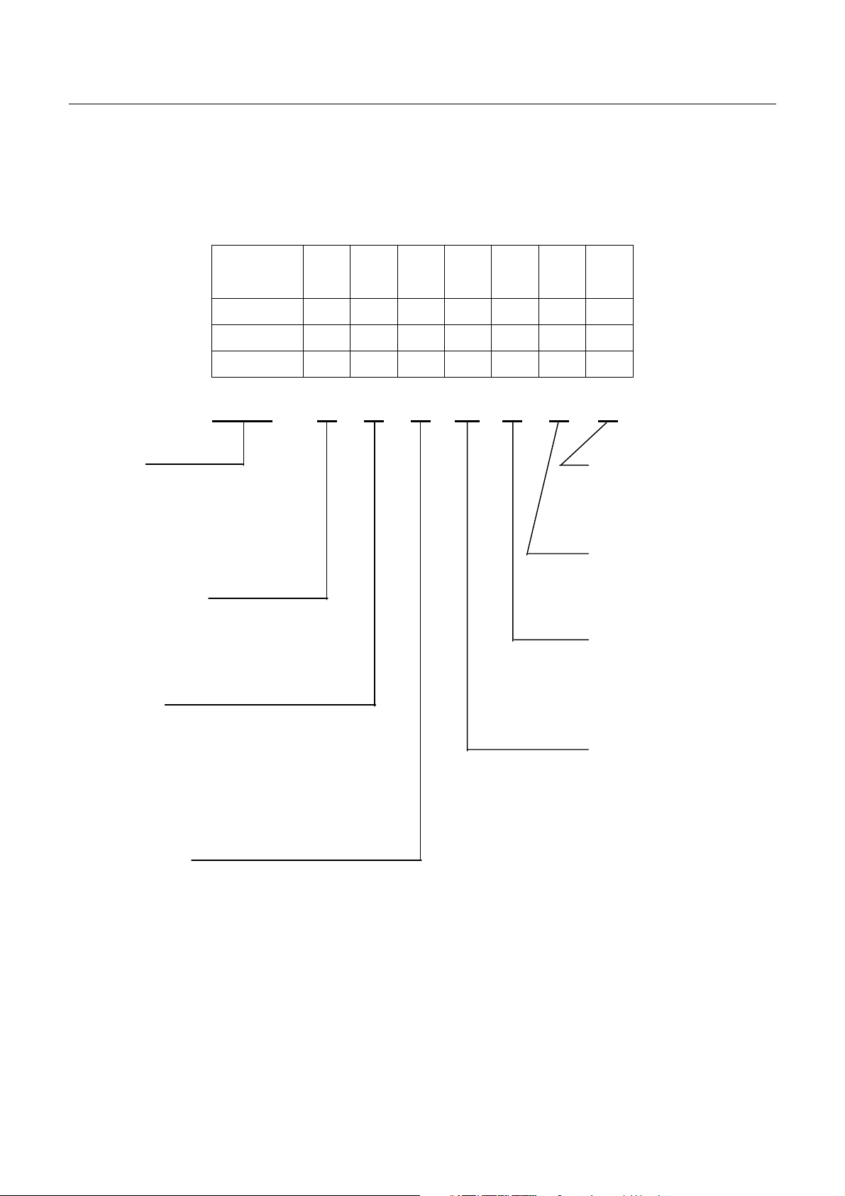
2. TYPE CLASSIFICATIONS
Printer types are classified according to the system shown below.
J
F
CBM-710
23
28
40
O
R
X
100
115
230
CBM-710/720/730/750 User’s Manual
G
C
B
N
V
–
CBM-720
CBM-730
CBM-750
↑ ↑ ↑ ↑ ↑ ↑
↑ ↑ ↑ ↑ ↑ ↑
↑ ↑ ↑ ↑ ↑ ↑
–
–
–
CBM-710 – 23 R J 100 G – B – V
Model
CBM-710
CBM-720
CBM-730
CBM-750
Column capacity
23: 23 columns
28: 28 columns
40: 40 columns
Interface
P : Parallel type P
R : Serial type R
RS-232C
20mA Current loop
X : RS422A
Character set
J : Japanese
F : International
Validation Function
V : With Validation
No symbol : Without Validation
Memory Back-up
B : With Back-up
N : Without Back-up
Mode
G : Graphic
C : Character
I : Character (Type II)
Power Source
100 : AC 100V
115 : AC 115V
230 : AC 230V
The exclusive paper winder mechanism (Model AW-2) is available separately. This mechanism can be mounted on
any of the printer types, except CBM-710, 720.
2
CITIZEN
Page 9
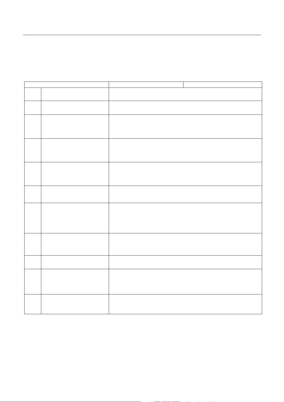
3. SPECIFICATIONS
3.1 General Specifications
Item CBM-710, 730 CBM-720, 750
1 Print Method Bidirectional serial dot impact method
CBM-710/720/730/750 User’s Manual
2 Character composition
3 Character number per line
4 Print speed
5 Character size
6 Line pitch
7 Paper size
8 Interface
7 × 7 dots (1ncl. half-dots)
23 columns: 230 dot/line
28 columns: 280 dot/line
40 columns: 360 dot/line
23 columns: approx.4.0 line/sec.
28 columns: approx. 3.5 line/sec.
40 columns: approx. 3.0 line/sec.
23 columns: 1.8(W) × 2.4 (H) mm
28 columns: 1.5(W) × 2.4 (H) mm
40 columns: 1.36(W) × 2.4 (H) mm
C: Character Type: 4.23 mm (1/6 inch)
G: Graphic Type: 2.82 mm (1/9 inch)
Friction Type: 76.0 ~ 0.5 mm (W) ×80 mm (Dia.)
3.0 inch (W) × 3.0 inch (Dia.)
Pin Wheel Type: 76 ~ 89 mm (W)
3 ~ 3.5 inch (W)
P: Parallel interface (8 Bit)
R: Serial interface (RS232C, 20 mA current loop)
X: Serial interface (RS422A)*
2
9 Input buffer 7K bytes or 2 line buffer
N Type: Without back-up.
10 Input buffer back-up
11 Paper end detection
B Type: Duration of back-up: More than 100 hours.
(But after 10 minutes operation)
When paper is near the end, the buzzer actuates and print operation is
interrupted, or PE signal is issued.
3
CITIZEN
Page 10
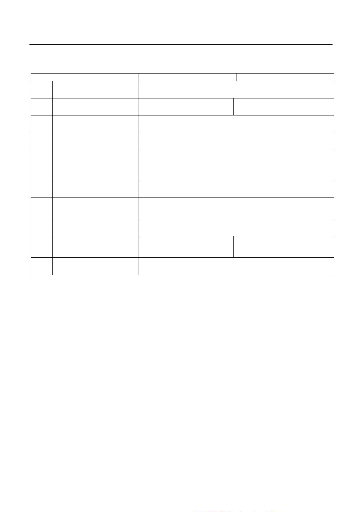
CBM-710/720/730/750 User’s Manual
Item CBM-710, 730 CBM-720, 750
12 Validation Print Available only for V-Type (1 line print)
13 Auto cutter Without cutter With cutter Partial cut/Full cut*3
14 Cassette ribbon Two color (Black and Red) print IR-61R/B*4
15 Paper winder Model AW-2 available as option
100V ± 10%, 50/60 Hz (For Japan)
16 Power voltage*5
115V ± 10%, 60 Hz (For United States)
230V ± 10%, 50/60Hz (For Europe)
17 Power consump. Approx. 30W
18 Operation temp. & humidity
5° to 35°C / 41° to 95°F
10% to 85% RH
19 Storage temp. -20° to 70°C
20 Net weight
Approx. 3.1 kg (710)
Approx. 3.3 kg (730)
Approx. 3.3 kg (720)
Approx. 3.6 kg (750)
21 External dimensions Refer to Section 14.
Notes: * l Paper weight of 45 kg refers to 1,000 sheets of 788 × 1,091 mm.
*2 RS-422A interface specifications are not included in this manual
1. With the RS422A type interface, only a one line input buffer can be selected.
2. However, when the input buffer is set for two lines, back-up of graphic data is not possible.
*3 Partial cut is three connecting points remaining. Full cut is one connecting point remaining.
*4 Single color print ribbon is available as option.
Black print: IR-61B
Purple print: IR-61P
V Type: Use only single color print ribbon.
*5 Power voltage setting is performed at the factory.
4
CITIZEN
Page 11
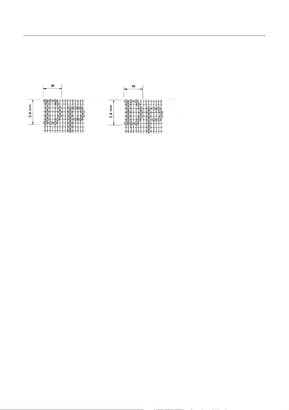
3.2 Print Format
(
(1) Character Font 7 × 7 dot.
23 columns: W = Approx. 1.8 mm
28 columns: W = Approx. 1.5 mm
7×7 dots
Incl. half-dots)
40 columns: W = Approx. 1.36 mm
7×7 dots (Incl. half-dots)
CBM-710/720/730/750 User’s Manual
3.3 Paper Specifications
(1) Form Friction specification :
Roll paper
76 - 0.5 mm (Width) × 80 mm (Outer dia.)
Pin wheel specification:
Fan fold paper
Width 76 mm (3 inches) ~ 89mm (3.5 inches)
(2) Type High quality paper with smooth surface
(3) Recommended Paper (Single paper) 45 - 55 kg/1000 sheets/1091 × 788 mm
(Copy) Non-carbon paper
Friction specification:
Original 1 + Copy 1, Each 34 kg paper
Total thickness: 0.13 mm or less
Pin wheel specification:
Original 1 + Copy 2
Use only single color print ribbon
Total thickness: 0.2 mm or less
5
CITIZEN
Page 12
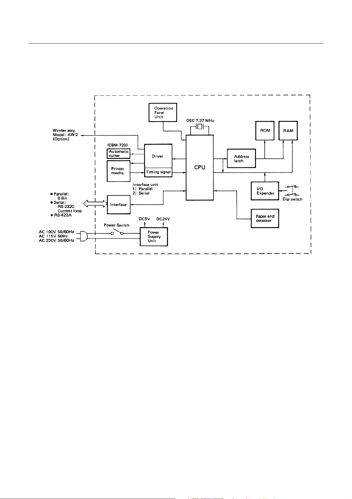
4. BLOCK DIAGRAM
CBM-710/720/730/750 User’s Manual
6
CITIZEN
Page 13
CBM-710/720/730/750 User’s Manual
5. EXTERNAL APPEARANCE AND PARTS DESCRIPTIONS
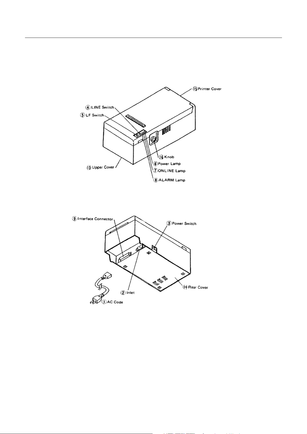
5.1 CBM-710 External Appearance
Fig. 1 Front View
Fig. 2 Rear View
7
CITIZEN
Page 14
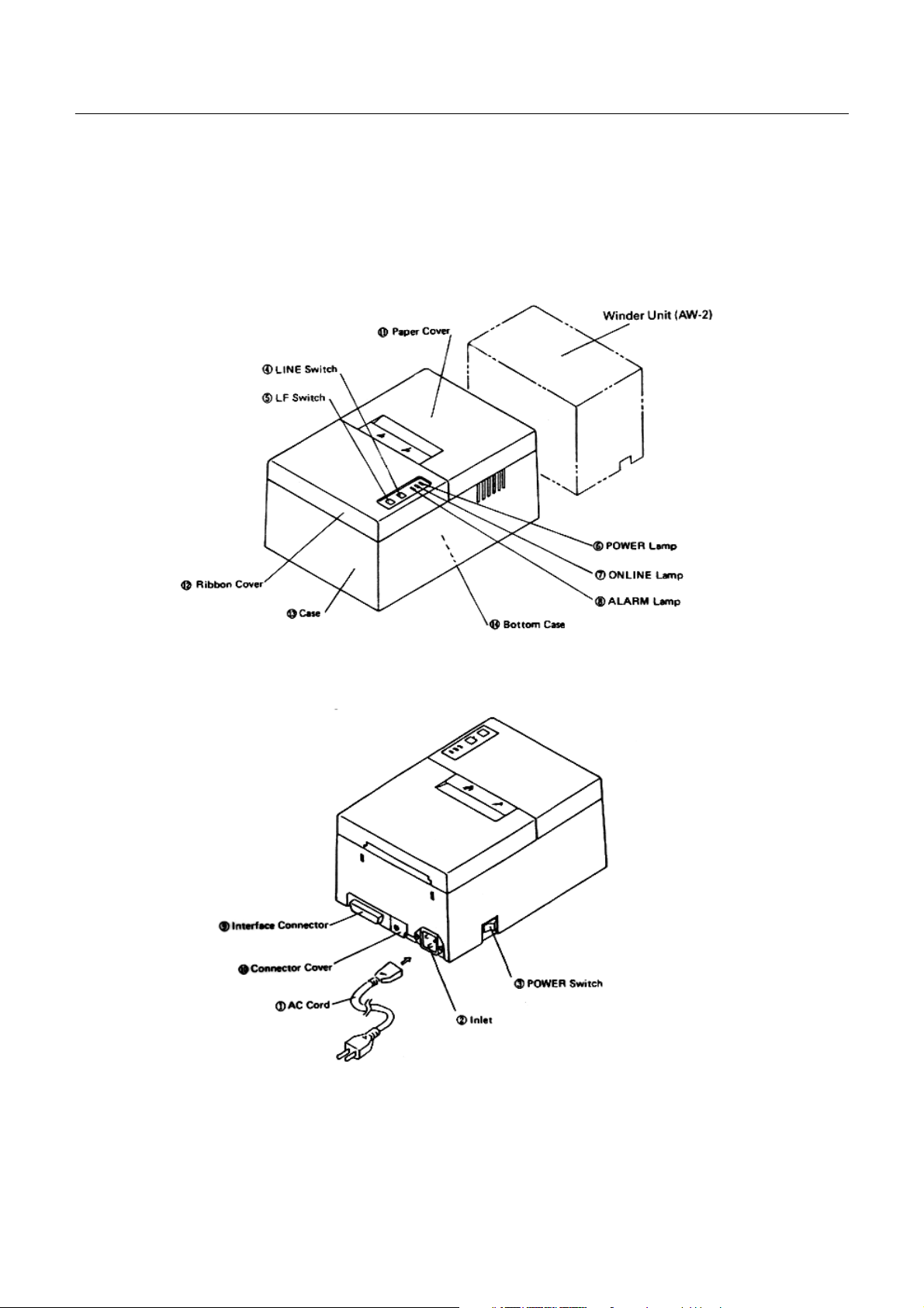
5.2 CBM-720 External Appearance
CBM-710/720/730/750 User’s Manual
Fig. 3 Front View
Fig. 4 Rear View
8
CITIZEN
Page 15
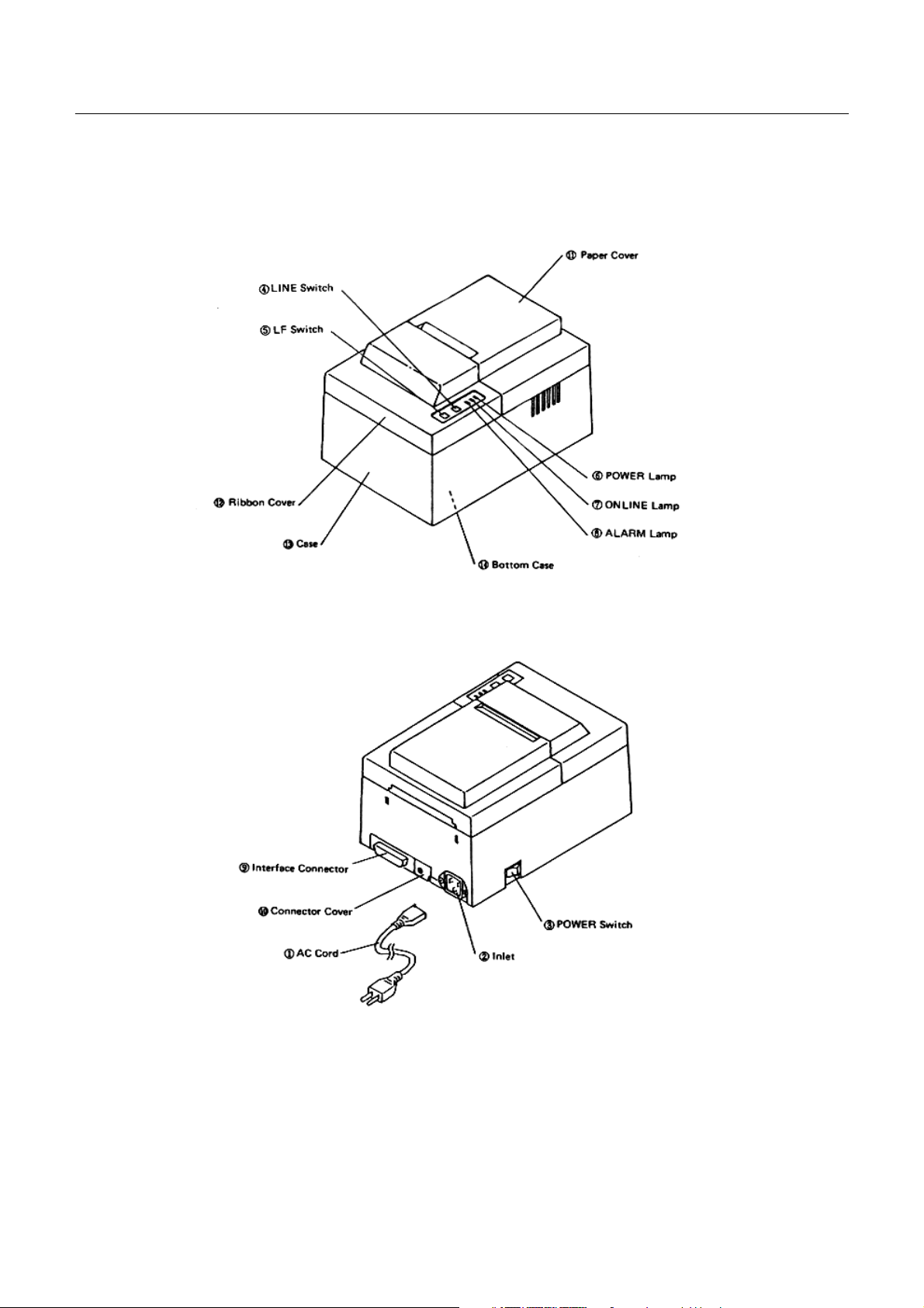
5.3 CBM-730 External Appearance
CBM-710/720/730/750 User’s Manual
Fig. 5 Front View
Fig. 6 Rear View
9
CITIZEN
Page 16
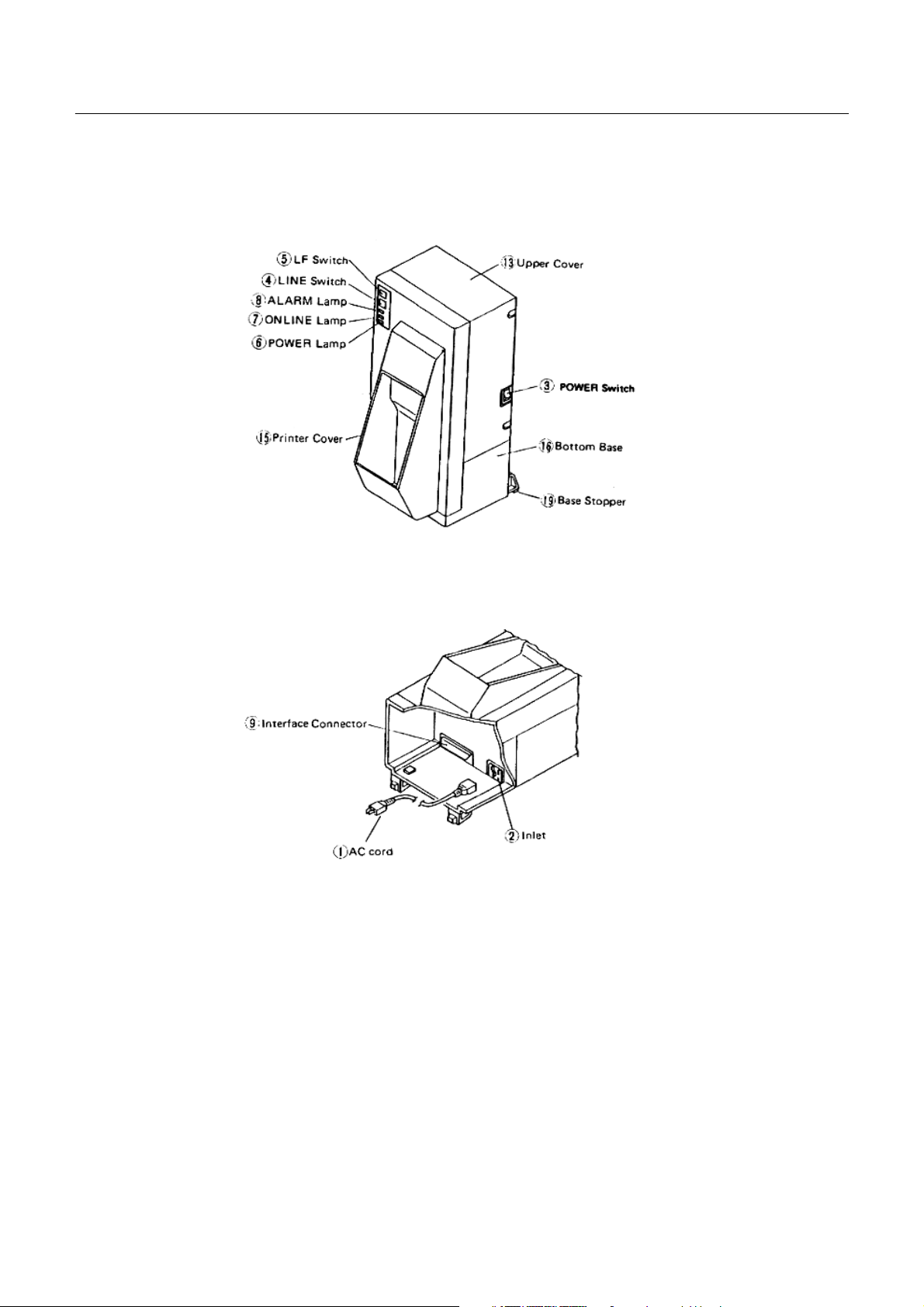
5.4 CBM-750 External Appearance
CBM-710/720/730/750 User’s Manual
Fig. 7 Front View
Fig. 9 Rear View
10
CITIZEN
Page 17

CBM-710/720/730/750 User’s Manual
5. 5 Part Descriptions
(1) Power Cord Attach the connector end to the printer inlet, and insert the plug end into an electric outlet.
(2) Inlet This is the electric power inlet. Attach the connector end of the power cord here.
(3 ) Power Switch Power is supplied to the printer by turning this switch on.
(4) Line Switch When this switch is pressed, the printer enters select (on line) status. When pressed again,
the printer enters deselect (off line) status. This switch is also used when clearing an alarm
condition.
(5) LF Switch Paper feeding is performed when this switch is pressed (in deselect status only). This is
used when inserting the paper and for spacing up etc.
(6) Power Lamp This lights up when the power switch is "on" and goes out when turned "off".
(7) On Line Lamp This lights up when the printer is in select (on line) status, and goes out when in deselect
(off line) status. Printing operation is performed only when this lamp is on.
(8) Alarm Lamp This lights up when printer operation is abnormal. When in an alarm condition, printing
and line feed operations are not performed.
(9) Interface Connector Connects through a cable to a computer etc. Please be certain that power to both
the printer and the computer are turned off when connection is made.
(l0) Connector Cover Covers the connector which is used for the paper winder mechanism (AW-2).
(l1) Paper Cover Opens when replacing the paper roll.
(l2) Ribbon Cover Opens when replacing the ribbon.
(l3) Top Case
(l4) Bottom Plate
(l5) Printer Cover
(l6) Paper-Feed Knob
(l7) Bottom Base
(l8) Base Stoppers
11
CITIZEN
Page 18
CBM-710/720/730/750 User’s Manual
6. OPERATION
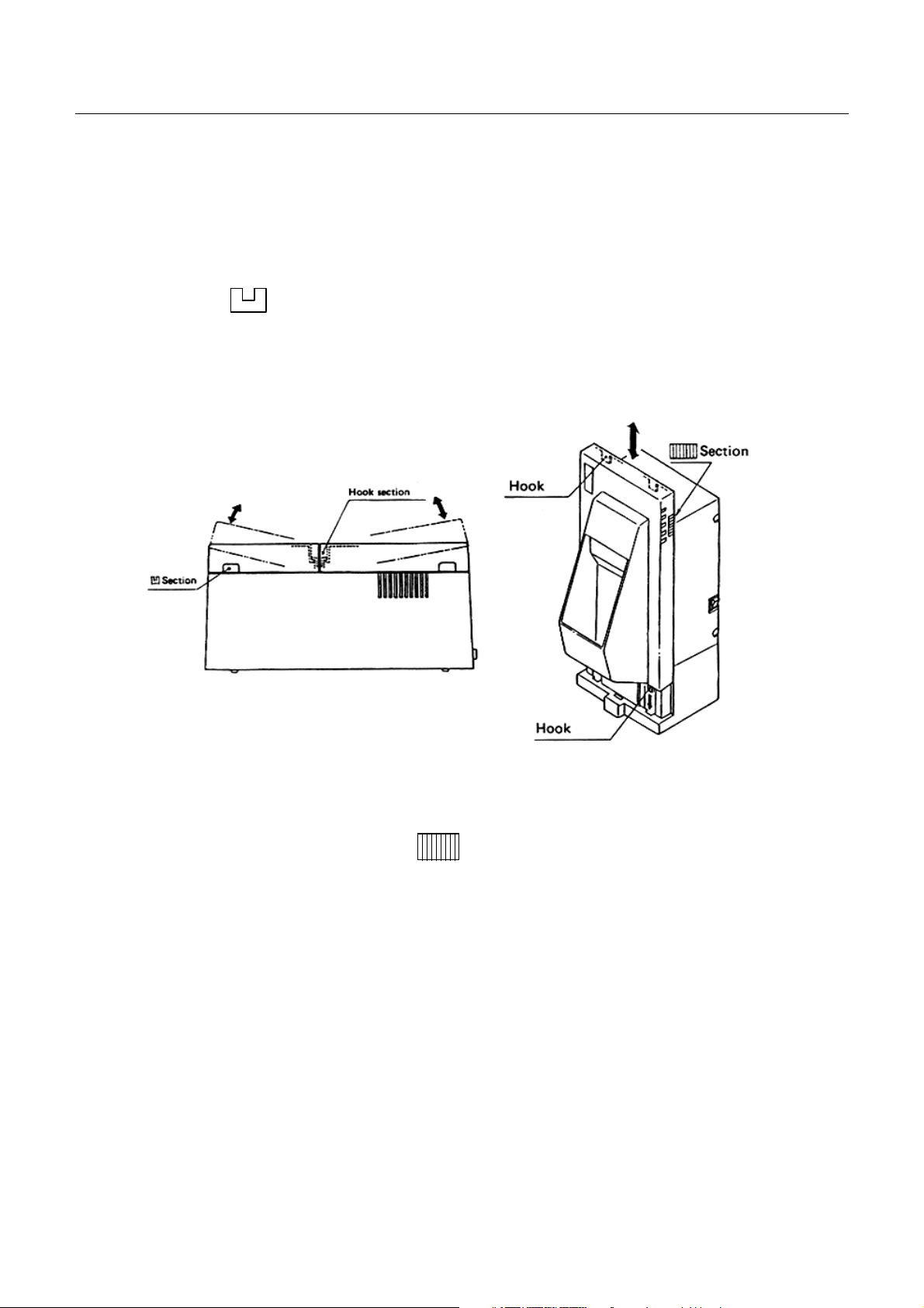
6. 1 Setting and Removing the Paper and Ribbon Covers
1) To open, grasp the sections of the cover with both hands and lift upward.
2) In order to replace the cover, engage the hook section in the middle and press downward in the direction of the
arrow.
3) To open the CBM-750's printer cover, grasp the (lines-engraved) section with both hands and lift upward.
4) For replacing the cover of the CBM-750, set 4 pieces of rear hooks into each square hole of the main unit, as
shown in figure 10.
Fig. 9 Fig. 10
12
CITIZEN
Page 19
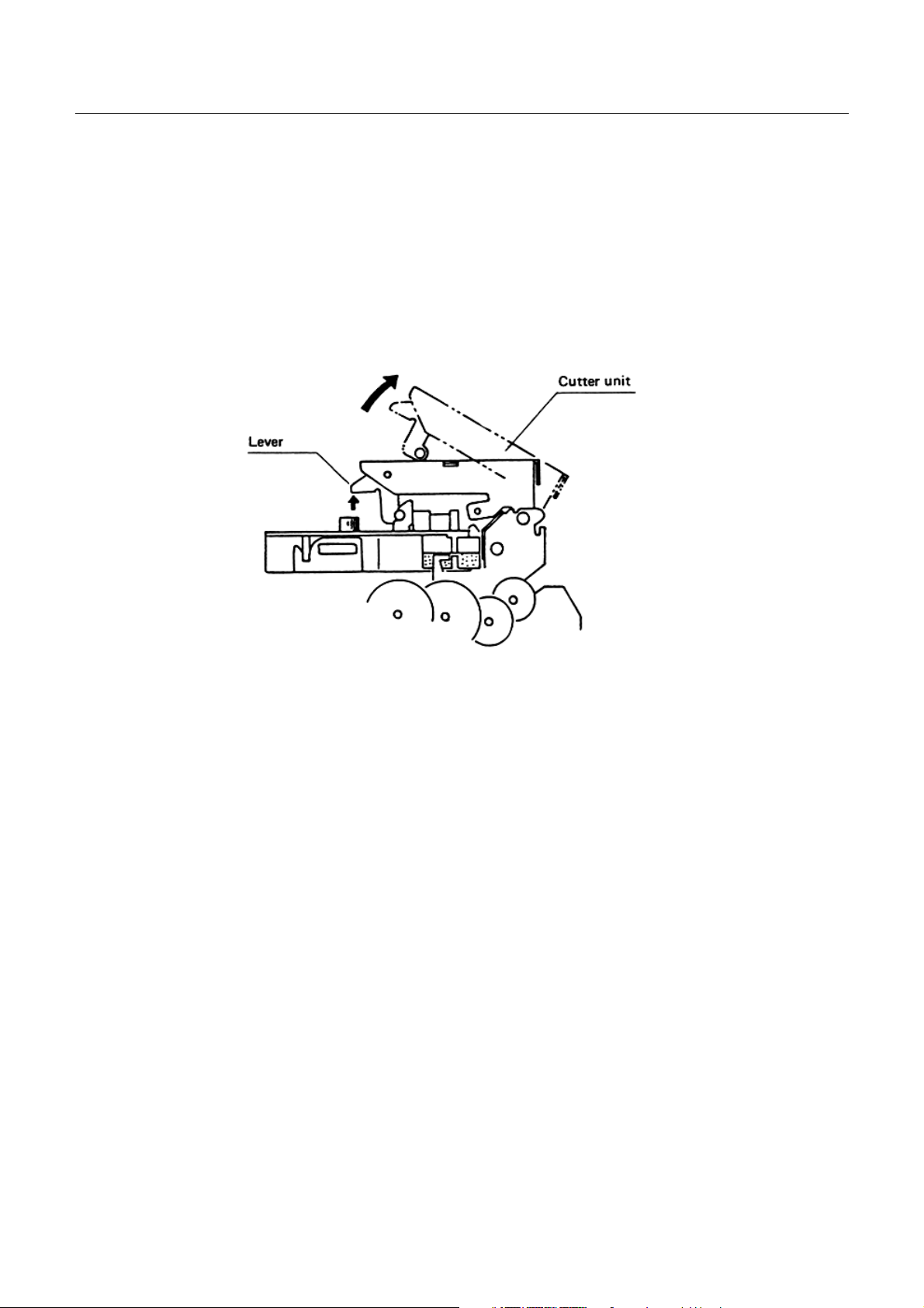
6.2 Opening and Closing the Cutter Unit (CBM-720. CBM-750)
1) To open the unit, grasp two levers and lift upward.
2) When closing the unit, press downward until it completely locks into place.
CBM-710/720/730/750 User’s Manual
Fig. 11
13
CITIZEN
Page 20
CBM-710/720/730/750 User’s Manual
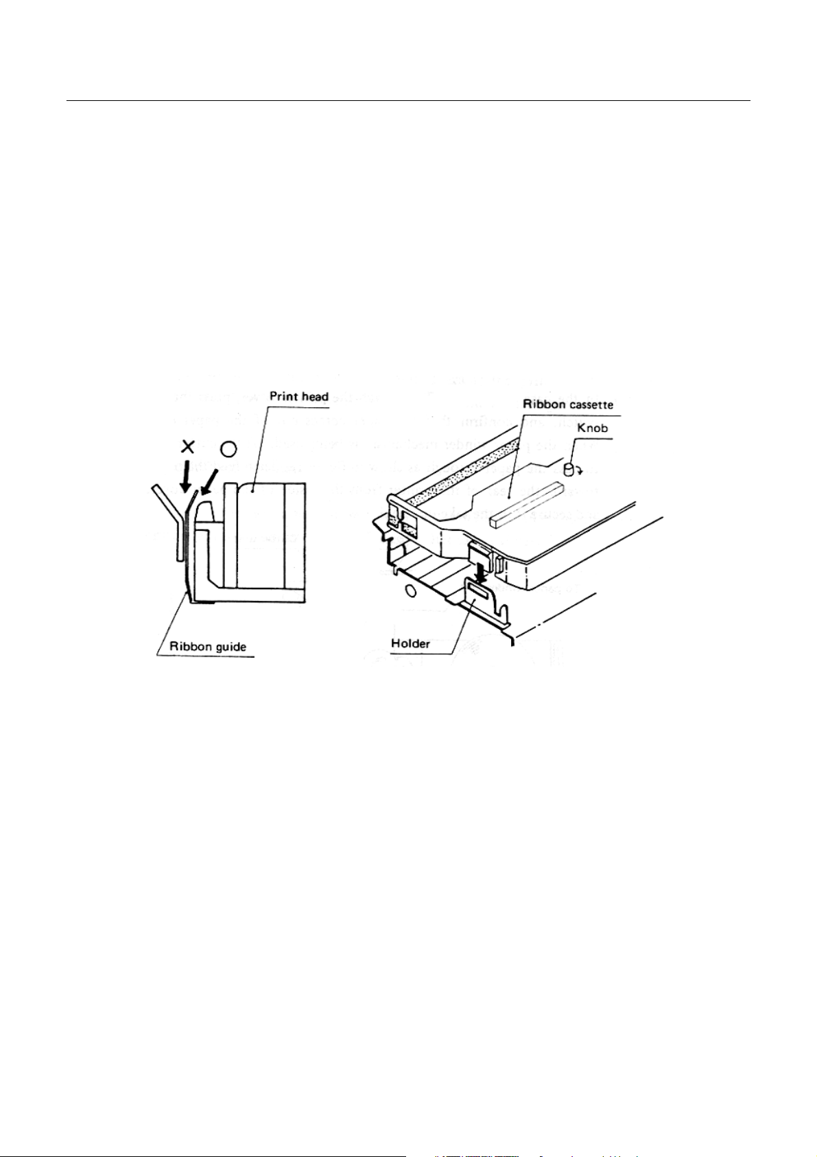
6.3 Installing the Cassette Ribbon
1) First remove the ribbon cover (CBM-710, CBM-730). In the case of the CBM-720, 750 remove both the ribbon
and paper covers and then open the cutter unit. (Refer to figures 9, 10 &11.)
2) While inserting the ribbon into the space between the print head and the ribbon guide, press the cassette into the
holder unit until it clicks into place. (Refer to figure 12 & 13.)
3) Turn the ribbon cassette knob in the direction of the arrow to take up slack in the ribbon.
Fig. 12
Fig. 13
14
CITIZEN
Page 21
CBM-710/720/730/750 User’s Manual
6.4 Installing and Changing the Paper
(1) Installing the Paper
1) Remove the paper cover.
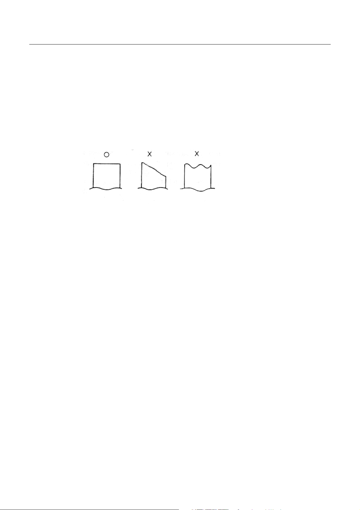
2) Cut the end of the paper off at a right angle as shown in figure 14.
Fig. 14
3) Put the end of the paper into the paper entrance of the printer. (Refer to figure 17.)
4) After turning the power switch on and confirming that the printer is in deselect (off line) status, press the LF
switch to feed the paper into the printer.
5) In the case of the CBM-730, set the imprint face of the paper downward and put it into the paper entrance (If
using 3.0" width paper, place the paper between 2 bars).
If necessary to adjust the sprocket-wheels' position, free them by the lever and slide to the appropriate position,
and lock it back. (Refer to figure 15.)
15
CITIZEN
Page 22
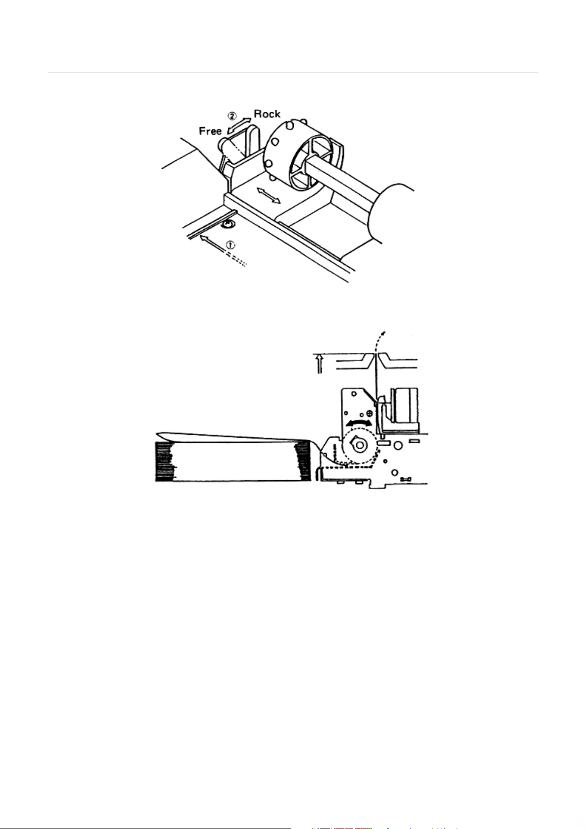
Fig. 15
CBM-710/720/730/750 User’s Manual
Fig. 16
Hook some of the paper's perforations on the sprockets and forward the paper into the printer by turning the paperfeed knob until the paper's tip protrudes 5 - 6 cm from the printer.
In the case of the CBM-710, use the LF switch to feed the paper.
16
CITIZEN
Page 23
CBM-710/720/730/750 User’s Manual
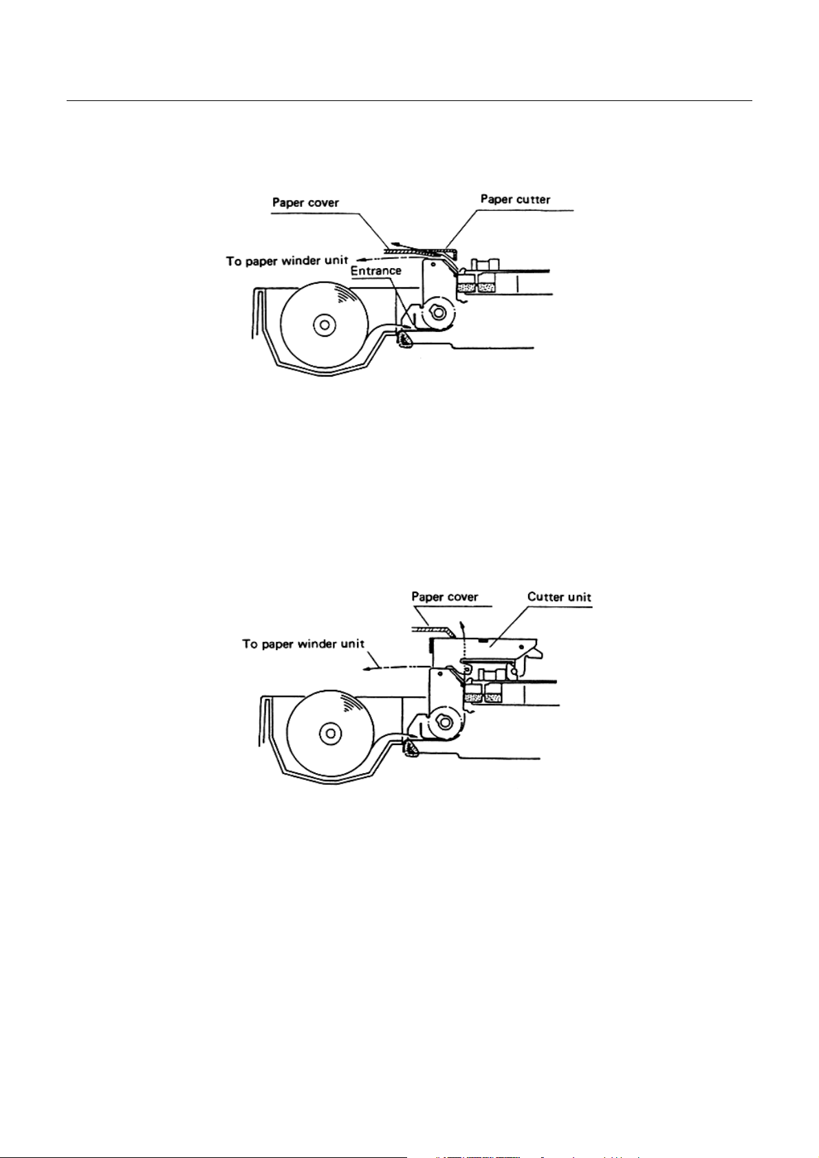
6) When using the paper winder mechanism (AW-2), feed the paper toward the rear of the printer from the
inside of the paper cover, and secure it to the take-up spool.
Fig. 17
7) In the case, of the CBM-720, attach the printer cover, press the LFswitch, and confirm that the paper comes
out of the paper exit. When the paper winder mechanism is being used, lift the cutter unit to pass the paper
through as shown in figure 18, Then feed the paper towards the rear of the printer from the inside of the paper
cover, and secure it to the take-up spool.
Fig. 18
17
CITIZEN
Page 24

CBM-710/720/730/750 User’s Manual
(2) Changing the Paper
1) Cut off the remaining paper near the entrance to the printer.
2) If the alarm lamp is on, turn it off by pressing the line switch.
3) Feed the paper out of the printer by pressing the LF switch or pull it out from the paper exit.
4) Install a new paper roll. (Refer to section 6.4 (1) Installing the paper.)
5) When the line switch is pressed again, the printer enters select (on line) status and printing may be resumed
once again.
6.5 Self Print Function
Your printer has a built in self print function for the purpose of checking print operation without the need for any
other external device.
Procedures for Actuating the Self Print Function
[1] Be sure that a paper roll is properly loaded.
[2] Confirm that the inked ribbon is properly installed and turn the power switch off.
[3] Turn the power switch ON while pressing the LF switch, and release the LF switch after the self print
operation has begun.
In the above operation, the se print unction will stop automatically when completed.
However, the self print function will not operate without paper when the printer is set for internal process of the
paper end detection function.
6.6 Paper End Detector
Your printer provides a paper end detection function which is able to detect when the paper is near the end. In
addition. two different responses to this situation may be selected.
[1] Issue the PE signal to an external unit(s).
[2] Perform internal processing, whereby the buzzer is sounded and the print operation of your printer is
interrupted.
18
CITIZEN
Page 25
CBM-710/720/730/750 User’s Manual
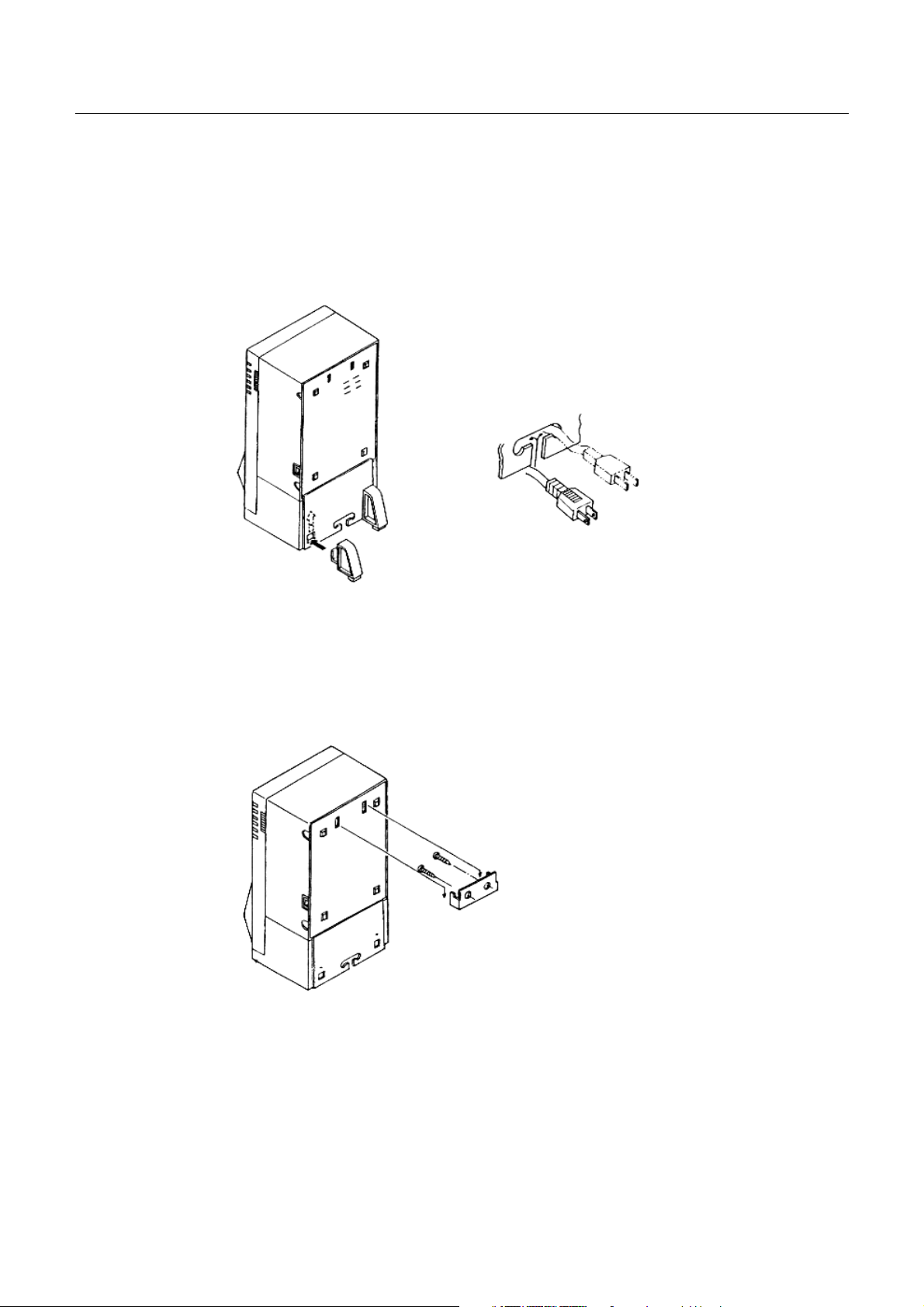
6.7 Installation of the CBM-750
1) Table-top use
Put the AC cord into the "T" hole of the bottom base. Install the base stoppers, as shown in the figure 19.
Fig. 19
2) Wall-mounting use
Fix the hanger with 2 screws to the wall and hook the unit as shown in the figure 20.
Fig. 20
19
CITIZEN
Page 26

CBM-710/720/730/750 User’s Manual
7. INPUT BUFFER BACK-UP FUNCTION
7.1 Input Buffer Back-up
If the power is turned off, or there is a power failure during printing, the data in the input buffer will be retained.
When the power comes back on, the power failure symbol (..... PD) will be printed in red, and then the data which
was interrupted will be printed from the beginning of the line where the interruption occurred.
Note: The input buffer back-up function may not operate properly if the related capacitor is not sufficiently charged.
This may be the case if the printer has not been operated for a long period of time. After the printer power
switch has been turned on for 10 minutes, the buffer back-up should be effective for approximately 100 hours
or more.
7.2 Clearing the Input Buffer
In case it is desired to delete the data in the input buffer, the power switch should be turned on while pressing the
LINE switch. When deletion of the buffer is completed the buzzer will sound. Please be sure to continue pressing the
LINE switch until that time.
If the printer fails to work properly at the time the power switch turned on, please delete the input buffer as described
above before inputting new data.
20
CITIZEN
Page 27

CBM-710/720/730/750 User’s Manual
8. PARALLEL INTERFACE
8.1 Specifications
a) Data Input system: 8 bit parallel (DATA 1 - 8).
b) Control Signals: ACK, BUSY, STB, FAULT, PE, RESET
c) Compatible Connectors: Printer side: 57LE-40360 (AMPHENOL or equivalent)
Cable side: 57-30360 (AMPHENOL or equivalent)
8.2 Connector Pin Assignment
Pin No. Signal Name Pin No Signal Name
1
2 DATA 1 20
3 DATA 2 21
4 DATA 3 22
5 DATA 4 23
6 DATA 5 24
7 DATA 6 25
8 DATA 7 26
9 DATA 8 27
10
11 BUSY 29
12 PE 30
13 +5V Level 31
14 GND 32
15 33 GND
16 GND 34
STB
ACK
19 Twisted Pair GND
↑
↑
↑
↑
↑
↑
↑
↑
28
↑
↑
↑
RESET
FAULT
17 FRAME GND 35
18 + 5V DC 36
21
CITIZEN
Page 28

CBM-710/720/730/750 User’s Manual
8.3 Description of Input/Output Signals
(1) Input/Output Signals
a) Input Signals (To Printer)
*DATA : 8 bit parallel signal. (Positive logic)
*STB : A strobe signal for reading in 8 bit data. (Negative logic)
*RESET : A signal which resets the entire printer. (Negative logic, 1 ms or more)
b) Output Signals (From Printer)
*ACK : This is a pulse signal for requesting 8 bit data, issued at the end of a BUSY signal.
(Negative logic)
*BUSY : This signal indicates that your printer is in a BUSY state. New data should be input
when this signal is "LOW". (Positive logic)
*FAULT : When your printer is in an alarm state, this signal is "LOW". At this time, all control
circuits of your printer are interrupted. (Negative logic)
*PE : When the paper is near its end, this signal is issued. (Positive logic)
Note: An alarm condition occurs when the timing of the print head movement sensor is abnormal.
c) Power Source
*+5V DC : The same +5V output as that of the power source which actuates the control circuits.
This should be less than 30 mA.
*GND : The common circuit ground.
*FRAME GND : Equivalent to "case ground".
22
CITIZEN
Page 29

(2) Electrical Characteristics
a) Input Signal Level
All input signals are TTL level.
"HIGH" level ..................2.0V Min.
"LOW" level.................... 0.8V Max.
b) Output Signal Level
"HIGH" level...................2.4V Min.
"LOW" level.................... 0.4VMax.
c) Input/Output Conditions
All of the input signals are pulled up by 1K ohms.
CBM-710/720/730/750 User’s Manual
All of the output signals are pulled up by 3.3K ohms.
23
CITIZEN
Page 30

(3) Timing Chart
a) Data Input and Print Timing
CBM-710/720/730/750 User’s Manual
(4) Data Receiving Control
Your printer is able to receive data sent from the host side when the BUSY signal is LOW, but unable to receive
when the BUSY signal is HIGH.
(5) Buffering
1) N Type
Your printer is provided with a two line input buffer.
2) B Type
Your printer is provided with a 7K byte input buffer. This makes possible a large amount of data buffering,
and therefore, the host side is free immediately after data transmission.
24
CITIZEN
Page 31

CBM-710/720/730/750 User’s Manual
9. SERIAL INTERFACE
9.1 Specifications
a) Synchronism : Asynchronous
b) Baud rate:
RS-232C type : 110, 150, 300, 600, 1200, 2400, 4800, 9600BPS (Selected by user)
Current Loop type : 110, 150, 300, 600, 1200BPS (Selected by user)
c) Composition of one word:
Start bit : 1bit
Data bit : 7 or 8 bits (selected by user)
Parity bit : Odd, even or no parity (Selected by user)
Stop bit : 1bit or more
d) Signal Polarity :
RS-232C type : *Mark = Logic "1" (-3V to -12V)
*Space = Logic "0" (+3V to +12V)
Current Loop type : *Mark = Logic "1" (Current ON)
*Space = Logic "0" (Current OFF)
e) Received Data:
RS-232C & Current Loop (RD signal)
*Mark = 1
*Space = 0
f) Receiving Control (DTR signal)
RS-232C : *Mark: Data Transfer not possible
*Space: Data Transfer possible
Current Loop: *Mark (Current ON): Data Transfer possible
*Space (Current OFF): Data Transfer not possible
g) Transmission Control (TD signal)
DC1 code (11H) "X" ON : Data Receiving possible
DC3 code (13H) "X" OFF: Data Receiving not possible
However, this is valid only for type B input buffer (7K).
25
CITIZEN
Page 32

9.2 Connector Pin Assignment
CBM-710/720/730/750 User’s Manual
Signal
Pin
Notes: [1] The signals for RS-232C use are based on EIA RS-232C level.
Compatible Connector (D-Sub connector) :
Return
Signal
Pin
1 FG
7 GND
3 RD
20 DTR
2 22 TD
11 PE
12
13 14 DTR
18 16 RD
23
[2] The loop current for Current Loop signal use should be restricted within the range of 10 to 20mA.
[3] Please always maintain the "mark state", when received data are not being transferred.
[4] The assignment of RS-232C/Current loop/TTL can be performed with the preset jumper
(Refer to 10. Slide Switch Setting).
*Printer: 17LE-13 250 (AMPHENOL or equivalent)
*Cable Side: 17JE-23 250 (AMPNENOL or equivalent)
Signal
Name
FAULT
RESET
Direction
Host/
Printer
→
←
←
←
←
←
→
→
Function RS-232C
Safety Ground O
Signal Ground O
Received Data O
Printer BUSY Signal O
Transmitted Date O O
Paper End Signal O
Printer ALARM Signal O
Printer BUSY Signal O
Received Data O
Printer RESET Signal O
Current
Loop
TTL
26
CITIZEN
Page 33

CBM-710/720/730/750 User’s Manual
9.3 Description of Input/Output Signals
(1) Input/Output Signals
a) RD :
This is the serial signal for received data. When framing, overrun or parity errors occur, the data concerned are
ignored.
b) DTR :
Please write in data or commands when this signal is in a "ready" state. If written in when in a BUSY state, an
overrun error will occur and the data will be ignored. Data can be written into the input buffer even during
printing. Further, a BUSY signal is generated when the power is turned on, while test printing, when ONLINEE
and during reset.
c) FAULT :
When there is a problem in the printer mechanism the FAULT signal will be issued, and all control circuits will
be interrupted. To RESET this signal, first correct the cause of trouble in the printer mechanism. Then, by
pressing the LINE switch or by inputting "0" (LOW LEVEL) at the RESET terminal, the FAULT can be cleared.
Causes of the FAULT signal are lack of paper and errors in the printer mechanism. Printer errors include such as,
the print head stopping during print operation or failure of the print head to return to the home position.
d) RESET:
This signal resets the entire printer.
e) PE :
This signal is output when the paper roll is near the end.
f) TD (Valid only for type B):
When receiving data signals, and when the printer's input buffer has less than 1K bytes remaining open, the DC3
code (13H) is issued, indicating that receipt of data is not possible. When the data in the input buffer is reduced
to 2K bytes, the DC1 (11H) code is issued, which indicates that data receipt is possible.
g) FG:
Frame Ground
h) GND:
Common ground for all circuits.
27
CITIZEN
Page 34

CBM-710/720/730/750 User’s Manual
(2) Data Composition
[1] Start bit
[2] Data bits (and parity bit)
[3] Stop bit (1 bit or more)
[1] Start bit
1/2 bit past the line dropping from MARK to SPACE, a status reading is taken again. If the reading is SPACE, a
start bit is recognized, but if it is MARK, it is not taken as a start bit. This is not regarded as an error, but the
search for the start bit is performed once again.
[2] Data bit and Parity bit
Data bits and parity bits are the data of the bits in question, which are represented by the state at the times
sampling is performed. This is accomplished at time intervals equal to one bit in length, beginning from the
middle of the start bit. The order of the bits is, starting with the bit closest to the start bit, bit-0, bit-1 ....., parity
bit. (Note: data bits are based on "one point sampling".)
[3] Stop bit
The stop bit consists of one or more bits at "mark" level. When "space" level is detected for a stop bit, a framing
error occurs.
(3) Error Detection
Parity, framing and overrun errors can be detected by your printer. When an error is detected, the ALARM lamp
goes on, the buzzer is sounded, the related data is abandoned, and the printer shifts to the next incoming data. The
ALARM lamp can be turned off by pressing the LINE switch.
[1] Framing error
When "space" state is detected during stop bit sampling, the ALARM lamp goes on, the buzzer sounds, and the
related data is ignored.
[2] Parity error
When parity check is designated, and if when checked an error is detected, the ALARM lamp goes on, the
buzzer sounds and the related data is ignored.
[3] Overrun error
When an overrun error is detected, the ALARM lamp goes on, the buzzer sounds and the related data is ignored.
28
CITIZEN
Page 35

CBM-710/720/730/750 User’s Manual
[4] Other errors
When trouble is detected in the printer mechanism, the ALARM lamp goes on, the buzzer is sounded, the
FAULT signal is output, and the DTR signal becomes BUSY. After the cause of the trouble has been corrected,
the ALARM lamp can be turned off by pressing the LINE switch or by making RESET = "0". When the printer
is put ONLINE, data receiving restarts.
(4) Data Receiving Control
When the BUSY signal is LOW, your printer receives data from the host side, but when this signal is HIGH, it
cannot receive data.
(5) Buffering
Data transfer to the input buffer is controlled by the DTR and TD signals. Please refer to 9.3 b) for the DTR
signal and 9.3 f) for the TD signal.
29
CITIZEN
Page 36

(6) Electrical Characteristics
a) RS-232C Circuit
Input (RD)
MAX232 or equivalent Mark = (-8V): Stop bit
Space = (-8V): Start bit
Output (DTR, TD, FAULT)
CBM-710/720/730/750 User’s Manual
MAX232 or equivalent
*DTR (–8V): BUSY *TD Mark = (–8V): 1
(+8V): READY Space = (+8V): 1
*FAULT (–8V): Normal
(+8V): Abnormal
30
CITIZEN
Page 37

b) Current Loop Circuit
Input (RD)
Output (DTR, TD)
Mark = Current ON
Space = Current OFF
CBM-710/720/730/750 User’s Manual
*DTR Current ON : READY
Current OFF : BUSY
*TD Mark = Current ON
Space = Current OFF
c) TTL Circuit
Output (PE)
7406 or equivalent
*PE H : Paper empty
L : Paper reaming
RESET
7406 or equivalent LOW for RESET
31
CITIZEN
Page 38

CBM-710/720/730/750 User’s Manual
10. FUNCTION SELECTION
In order to meet the widest possible range of needs, various conditions can be selected by setting the DIP
switches and slide switches.
(1) Setting DIP Switch DS1
No. Function Off On
1 Auto Cutter No Yes *1
2 Off
International country switching (Refer to the table below)
3
4 Input buffer 7K Byte 2 Line *1
Factory
Setting
Off
5 Character direction Normal Inverted *1
6 CR cord CR CR + LF Off
7 Mode Character Graphic *1
8 SEL/DESEL at "power on" SELECT DESELECT Off
Note : *1) Setting is variable, depending on the type of printer.
No. USA FRANCE W.GERMANY ENGLAND
2 OFF ON OFF ON
3 OFF OFF ON ON
32
CITIZEN
Page 39

CBM-710/720/730/750 User’s Manual
(2) DIP Switch DS2 (Serial interface specifications only)
No . Function OFF ON
Factory
Setting
l Word length setting 8 bits 7 bits OFF
2 Parity check YES NO ON
3 Parity condition ODD EVEN OFF
4 Not in use
5 OFF
6 OFF
Baud rate setting (Refer to the table below)
7 ON
8
OFF
bps No 110 150 300 600 1200 2400 4800 9600
5 OFF ON OFF ON OF F ON OFF ON
6 OFF OFF ON ON OF F OFF ON ON
7 OFF OFF OFF OFF ON ON ON ON
8 OFF OFF OFF OFF OFF OFF OFF OFF
33
CITIZEN
Page 40

CBM-710/720/730/750 User’s Manual
(3) Slide Switch Setting (Serial interface specifications only)
RS232-C or 20mA current loop can be selected by changing slide switch SW1 on the control board. The side
labeled "RS" is for RS232-C and the side labeled "CL" is for 20mA current loop. The switch is set at the factory for
RS232-C.
(4) DIP Switch and Slide Switch Locations
DIP switches and slide switches are mounted on the control board to make function selection possible. When
function selection is performed, remove the printer bottom cover.
Special care should be taken to avoid damage to electronic parts and wiring. Furthermore, be sure to disconnect
the power plug from the electric outlet before opening the printer case.
Note: 1. DS2 is mounted for RS232C and RS422A type only.
2. SW1 is mounted for RS232C type only.
34
CITIZEN
Page 41

11. PRINT CONTROL FUNCTIONS
11.1 Control Codes
Function cord Hex. Code Functions
FF + n 0C+n "n-line" paper feed command
SO 0E Enlarged character command
SI 0F Normal character command
LF 0A Paper feed command
CR 0D Print command
DC1 11 Initial set command
CBM-710/720/730/750 User’s Manual
DC2 12 Inverted character command
DC3 13 Red color print command
CAN 18 Clear command
ESC+P+0 1B, 50, 00 Paper full cut command
ESC+P+1 1B, 50, 01 Paper partial cut command
ESC+P+2 1B, 50, 02 Validation print
BEL 07 Buzzer command
ESC + - + n 1B, 2D, n Underline command
ESC + * + n1 + n2
ESC + 1 1B, 31 1/9 inch paper feed preset command
ESC + 2 1B, 32 2/9 inch paper feed preset command
ESC + C + n 1B, 43, n Page length set command
1B, 2A, n1 , n2 Graphic command
ESC + f + 1 1B, 66, 01 Form feed command
ESC + N + n 1B, 4E, n "n-line" skip perforation command
ESC + 0 1B, 4F Skip perforation cancel command
35
CITIZEN
Page 42

CBM-710/720/730/750 User’s Manual
11.2 Input Data Formats
(1) Paper feed command for "n" lines
D8 D1
1st byte 0 0 0 0 1 1 0 0 FF (0C)H + n
D8 D1
2nd byte
When the number of lines to be fed (2hd byte) is written-in following the paper feed command (1st byte), the
paper will be fed by the number of lines specified. The number of lines to be fed can be specified from n=1 to 127. If
"0" is specified, paper feed will not be carried out. When there is data in the print buffer at the time this command is
applied, this data will first to printed out and then line feeding of "n" lines will be performed.
(2) Enlarged character command
D8 D1
N7 N6 N5 N4 N3 N2 N1 N7 ~ N1 (Binary digits)
0 0 0 0 1 1 1 0 SO (0E)H
The data following this command, are printed out in twice the normal width. This mode will continue until the
corresponding cancel command is input, or automatically released after printing one line. Since enlarged characters
are twice the normal width, care should be taken to avoid exceeding the column capacity.
36
CITIZEN
Page 43

CBM-710/720/730/750 User’s Manual
(3) Enlarged character cancel command
D8 D1
0 0 0 0 1 1 1 1 SI (0F)H
This command is used or canceling e enlarge character mode set by SO, and the following data will be printed
out in the normal character mode.
(4) Paper feed command
D8 D1
0 0 0 0 1 0 1 0 LF (0A)H
When there is data in the internal print buffer, line feed will be carried out after printing is completed. When the
buffer is empty, line feed only will be carried out.
(5) Print command
D8 D1
0 0 0 0 1 1 0 1 CR (0D)H
By means of this command, line feed is performed after printing is completed. In order to accommodate the print
data output formats of various computers, the CR function is selectable. (Please refer to 10 (1) DIP Switch Setting)
(6) Clear command
D8 D1
0 0 0 1 1 0 0 0 CAN (18)H
Print data previously entered on the same line can be cleared by the command.
(7) Red color print command
D8 D1
0 0 0 1 0 0 1 1 DC3 (13)H
This command specifies red colored characters and all of the characters on one line will be printed in red. Since
this command is cancelled after printing one line, it is necessary to use it for each line on whith red printing is
desired.
(8) Initial Set Command
37
CITIZEN
Page 44

CBM-710/720/730/750 User’s Manual
D8 D1
0 0 0 1 0 0 0 1 DC1 (11)H
The controller is initialized by this command and the following conditions are established.
* Internal input buffer cleared
* Normal character mode selected
* Black color print mode selected
* Skip designation cancelled
* Page length set to 66 lines
* Line feed pitch set to 219 inch (graphic type only)
(9) Inverted character command
D8 D1
0 0 0 1 0 0 1 0 DC2 (12)H
This command specifies inverted characters. By entering this command at the beginning of print data and then
sending the data to the controller, all of the following characters will be printed upside down. This command remains
valid until, either it is entered again or the initial set command is entered.
(10) Buzzer Command
D8 D1
0 0 0 0 0 1 1 1 BEL (07)H
Command to activate the alarm buzzer for 0.3 second period.
38
CITIZEN
Page 45

(11) Underline Command
D8 D1
1st byte 0 0 0 1 1 0 1 1 ESC (1B)H
D8 D1
2nd byte 0 0 1 0 1 1 0 1 – (2D)H
D8 D1
3rd byte
N1 n (Binary digital)
When n=1, the underline mode is set, and when n=0, it is cancelled.
(12) Graphic Command (Graphic Type Only)
D8 D1
CBM-710/720/730/750 User’s Manual
1st byte 0 0 0 1 1 0 1 1 ESC (1B)H
D8 D1
2nd byte 0 0 1 0 1 0 1 0 * (2A)H
D8 D1
3rd byte n
(Binary digital)
1
D8 D1
4th byte n
(Binary digital)
2
Bit image mode printing is performed by this command. (n2 is the quotient when divided by 256, and n1 is the
remainder.) When data is received only for numbers specified by n1 and n2, printing and line feed are carried out
automatically, and the bit image mode is cancelled.
39
CITIZEN
Page 46

CBM-710/720/730/750 User’s Manual
However, since "half-dots" are being used, the next corresponding pin cannot print at the same time. Further, the
maximum value of n1 and n2 is the number contained in one line, and this cannot be exceeded.
Relation of Head Pins to Data
1 pin
9 pin
D8 D7 D6 D5 D4 D3 D2 D1 DATA
(13) 1/9 inch Line Feed Pitch Set Command (Graphic Type)
D8 D1
1st byte 0 0 0 1 1 0 1 1 ESC (1B)H
D8 D1
2nd byte 0 0 1 1 0 0 0 1 1 (31)H
(14) 2/9 inch Line Feed Pitch Set Command (Graphic Type)
D8 D1
1st byte 0 0 0 1 1 0 1 1 ESC (1B)H
D8 D1
2nd byte 0 0 1 1 0 0 1 0 2 (32)H
40
CITIZEN
Page 47

(15) Page Length Set Command
D8 D1
1st byte 0 0 0 1 1 0 1 1 ESC (1B)H
D8 D1
2nd byte 0 1 0 0 0 0 1 1 C (43)H
D8 D1
3rd byte
N7 N6 N5 N4 N3 N2 N1 n
The length of one page is set to "n" lines by this command.
(1 ≤ n ≤ 127)
(16) Form Feed Command
D8 D1
CBM-710/720/730/750 User’s Manual
(Binary digital)
1st byte 0 0 0 1 1 0 1 1 ESC (1B)H
D8 D1
2nd byte 0 1 1 0 0 1 1 0 f (66)H
D8 D1
3rd byte 0 0 0 0 0 0 0 1 1
(01)H
The input of this command feeds the paper to the top of the next page, after printing the data contained in the
print buffer.
41
CITIZEN
Page 48

(17) Skip Perforation Command
D8 D1
1st byte 0 0 0 1 1 0 1 1 ESC (1B)H
D8 D1
2nd byte 0 1 0 0 1 1 1 0 N (4E)H
D8 D1
3rd byte
N7 N6 N5 N4 N3 N2 N1 n
This command feeds the paper (skips) n lines without any printing.
However, this cannot exceed the length of one page (1 ≤ n ≤ 126)
(18) Skip Perforation Cancel Command
D8 D1
CBM-710/720/730/750 User’s Manual
(Binary digital)
1st byte 0 0 0 1 1 0 1 1 ESC (1B)H
D8 D1
2nd byte 0 1 0 0 1 1 1 1 0 (4F)H
This command cancels the skip perforation function.
(19) Validation Print Command
D8 D1
1st byte 0 0 0 1 1 0 1 1 ESC (1B)H
D8 D1
2nd byte 0 1 0 1 0 0 0 0 P (50)H
D8 D1
3rd byte 0 0 0 0 0 0 1 0 2
(02)H
Validation printing is performed by this command (one line only).
* This command cannot be used for printers with cutter specifications (Type A).
42
CITIZEN
Page 49

(18) Full Cut Command
D8 D1
1st byte 0 0 0 1 1 0 1 1 ESC (1B)H
D8 D1
2nd byte 0 1 0 1 0 0 0 0 P (50)H
D8 D1
CBM-710/720/730/750 User’s Manual
3rd byte 0 0 0 0 0 0 0 0 0
(00)H
A full cut of the paper is performed by this command (one connecting point remaining).
(20 ) Partial Cut Command
D8 D1
1st byte 0 0 0 1 1 0 1 1 ESC (1B)H
D8 D1
2nd byte 0 1 0 1 0 0 0 0 P (50)H
D8 D1
3rd byte 0 0 0 0 0 0 0 1 1
(01)H
A partial cut of the paper is performed by this command (one connecting point remaining).
43
CITIZEN
Page 50

12. CHARACTER CODE TABLES
International Character Codes
CBM-710/720/730/750 User’s Manual
The following codes are set as space characters.
20H, 80H-9FH, E0H-FFH.
44
CITIZEN
Page 51

Individual Country Character Codes
CBM-710/720/730/750 User’s Manual
45
CITIZEN
Page 52

CBM-710/720/730/750 User’s Manual
13. MAINTENANCE
13.1 Maintenance Procedures
It is recommended that users perform periodic cleaning of their printer.
(1) Exterior :
The exterior case of the printer can be cleaned with alcohol. Care should be taken to keep water from reaching
the electronic parts and the printing mechanism .
(2 ) Interior :
There is no particular requirement, however, when the printer case is opened to change settings etc., dust and
other foreign matter may be removed from the printer mechanism and circuit boards with a soft brush.
Special care should be taken to avoid damage to electronic parts and wiring. Furthermore, be sure to disconnect
the power plug from the electric outlet before opening the printer case.
46
CITIZEN
Page 53

14. EXTERNAL DIMENSIONS
14.1 CBM-710
CBM-710/720/730/750 User’s Manual
47
CITIZEN
Page 54

14.2 CBM-720
CBM-710/720/730/750 User’s Manual
48
CITIZEN
Page 55

14.3 Paper Winder Unit AW-2
CBM-710/720/730/750 User’s Manual
49
CITIZEN
Page 56

14.4 CBM-730
CBM-710/720/730/750 User’s Manual
50
CITIZEN
Page 57

14.5 CBM-750
CBM-710/720/730/750 User’s Manual
51
CITIZEN
Page 58

CBM-710/720/730/750 User’s Manual
<<< German >>>
52
CITIZEN
Page 59

CBM-710/720/730/750 User’s Manual
3. TECHNISCHE DATEN
3.1 Allgemeine Daten
Gegenstand CBM-710, 730 CBM-720, 750
1 Druckprinzip Serieller mechanischer Zweirichtungs-Matrixdrucker
2 Zeichenaufbau 7 × 7 Punkte (einschl. Halbpunkte)
23 Spalten: 230 Punkte/Zeile
3 Zeichenanzahl pro Zeile
4 Druckgeschwindigkeit
28 Spalten: 280 Punkte/Zeile
40 Spalten: 360 Punkte/Zeile
23 Spalten: ca. 4,0 Zeilen/Sek.
28 Spalten: ca. 3,5 Zeilen/Sek.
40 Spalten: ca. 3,0 Zeilen/Sek.
23 Spalten: 1,8 (B) × 2,4 (H) mm
5 Zeichengröße
6 Zeilenabstand
7 Papierformat
8 Schnittstelle
9 Eingangspuffer 7 Kilobyte oder 2 Zeilen
10 Eingangspuffer-Sicherung
11 Papierende-Detektion
28 Spalten: 1,5 (B) × 2,4 (H) mm
40 Spalten: 1,36 (B) × 2,4 (H) mm
Typ C: Zeichen: 4,23 mm (1/6 Inch)
Typ G: Grafik 2,82 mm (1/9 Inch)
Friktionsantrieb: 76,0 ~ 0,5 mm (B) × 80 mm (Diagonale)
3,0 Inch (B) × 3,0 Inch (Diagonale)
Stachelradantrieb: 76 ~ 89 mm (B)
3 ~ 3,5 Inch (B)
P: Parallele Schnittstelle (8 Bit)
R: Serielle Schnittstelle (RS232C, 20 mA Linienstrom)
X: Serielle Schnittstelle (RS422A)*
Typ N: Keine Datensicherung
Typ B: Sicherungsdauer: Über 100 Std.
(aber nach 10 Minuten Betrieb)
Kurz vor Papierende wird der Summer aktiviert und der Druckbetrieb
unterbrochen oder ein PE-Signal ausgegeben.
2
53
CITIZEN
Page 60

Gegenstand CBM-710, 730 CBM-720, 750
12 Belegdruck Nur für Typ V verfügbar (1-Zeilen-Druck)
CBM-710/720/730/750 User’s Manual
13 Automatischer Papierschneider Ohne Papierschneider
Mit Papierschneider
Teilschnitt/Vollschnitt*
14 Farbbandkassette Zweifarbendruck (Schwarz & Weiß) IR-61R/B*4
15 Papieraufwickler Modell AW-2 als Option erhältlich
100 V ± 10 %, 50/60 Hz (für Japan)
16 Versorgungsspannung*5
115 V ± 10 %, 50/60 Hz (für U.S.A.)
230 V ± 10 %, 50/60 Hz (für Europa)
17 Leistungsaufnahme Ca. 30 W
Betriebstemperatur &
18
Luftfeuchtigkeit
5° bis 35° C/41° bis 95° F
10 % bis 85 % rel. Luftfeuchtigkeit
19 Lagertemperatur -20° bis 70° C
20 Nettogewicht
Ca. 3,1 kg (710)
Ca. 3,3 kg (730)
Ca. 3,3 kg (720)
Ca. 3,6 kg (750)
21 Außenabmessungen Siehe Abschnitt 14
3
Hinweise: * l Das Papiergewicht von 45 kg bezieht sich auf 1.000 Blatt Größe 788 × 1.091 mm.
*2 Die technischen Daten der RS-422A-Schnittstelle sind in dieser Bedienungsanleitung nicht enthalten.
1. Ohne RS-422A-Schnittstelle ist nur ein Einzeilen-Eingangspuffer wählbar.
2. Wenn der Eingangspuffer auf zwei Zeilen eingestellt wird, ist Sichern von Grafikdaten nicht
möglich.
*3 Bei Teilschnitt verbleiben drei verbindende Stellen. Bei Vollschnitt verbleibt eine verbindende Stelle.
*4 Einfarbiges Farbband als Option erhältlich.
Schwarzdruck: IR-61B
Purpurdruck: IR-61P
Typ V: Nur einfarbiges Farbband verwenden.
*5 Die Versorgungsspannung wird im Werk eingestellt.
54
CITIZEN
Page 61

3.2 Druckformat
(
(1) Zeichensatz 7 × 7 Punkte
B
CBM-710/720/730/750 User’s Manual
B
2,4 mm
2,4 mm
23 Spalten: B = Ca. 1,8 mm
28 Spalten: B = Ca. 1,5 mm
7 × 7 Punkte
einschl. Halbpunkte)
40 Spalten: W = Ca. 1,36 mm
7 × 7 Punkte (einschl. Halbpunkte)
3.3 Papierdaten
(1) Form Bei Friktionsantrieb:
Papierrolle
76 - 0,5 mm (Breite) × 80 mm (Außendurchmesser)
Bei Stachelradantrieb:
Zickzackgefaltetes Papier
Breite 76 mm (3 Inch) ~ 89 mm (3.5 Inch)
(2) Typ Hochwertiges Papier mit glatter Oberfläche
(3) Empfohlenes Papier (Einzelblatt) 45 - 55 kg/1000 Blatt/1091 × 788 mm
(Kopie) Noncarbonpapier
Bei Friktionsantrieb:
1 Original + 1 Kopie, jeweils 34-kg-Papier
Gesamtdicke: max. 0,13 mm
Bei Stachelradantrieb:
1 Original + 2 Kopien
Nur einfarbiges Farbband verwenden
Gesamtdicke: max. 0,2 mm
55
CITIZEN
Page 62

5. AUSSENANSICHT UND BESCHREIBUNG DER TEILE
5.2 CBM-720 Außenansicht
4 Line-Taste
5 Zeilenvorschubtaste (LF)
CBM-710/720/730/750 User’s Manual
11
Papierfachabdeckung
6 Netzkontrolllampe
12
Farbbandabdeckung
13
Gehäuse
14
Bodenplatte
7 Online-Kontrolllampe
8 Alarm-Kontrolllampe
Abb. 3: Ansicht von vorn
9 Schnittstelle
10
Anschlussabdeckung
3 Netzschalter
1 Netzkabel
2 Netzeingang
Abb. 4: Ansicht von hinten
56
CITIZEN
Page 63

CBM-710/720/730/750 User’s Manual
5. 5 Beschreibung der Teile
(1) Netzkabel Den Verbinder an den Netzeingang des Druckers und den Netzstecker an eine
Netzsteckdose anschließen.
(2) Netzeingang Zur Stromversorgung. Hier den Verbinder des Netzkabels anschließen.
(3 ) Netzschalter Zum Ein- und Ausschalten der Drucker-Stromversorgung.
(4) Line-Taste Schaltet den Drucker auf rechnergesteuerten „Select”-Betrieb (Online-Status). Erneutes
Drücken schaltet auf rechnerunabhängigen „Deselect”-Betrieb (Offline-Status). Die Taste
dient auch zum Annullieren von Alarmzuständen.
(5) Zeilenvorschubtaste Auf Drücken dieser Taste erfolgt Papiervorschub (nur im Offline-Status). Wird zum
(LF) Einführen des Papiers und zum Hochfahren des Papiers verwendet.
(6) Netzkontrolllampe Leuchtet bei eingeschaltetem Drucker und ist bei ausgeschaltetem Drucker erloschen.
Online-K ontrolllam pe
(7)
Alarm -Kontrolllampe
(8)
(9) Schnittstelle Zum Anschließen an einen Computer, etc. Beachten Sie beim Anschließen des Kabels,
Anschlussabdeckung
(l0)
Papierfachabdeckung
(l1)
(l2) Farbbandabdeckung Zum Wechseln des Farbbands abnehmen.
(l3) Oberes Gehäuse
(l4) Bodenplatte
(l5) Druckerabdeckung
(l6) Papiervorschubtaste
Leuchtet im rechnergesteuertem „Select”-Zustand (Online-Status) und ist erloschen, wenn
der Drucker im rechnerunabhängigen „Deselect”-Zustand (Offline-Status) ist. Drucken
erfolgt nur bei leuchtender Lampe.
Leuchtet bei nicht normalem Druckerzustand. Im Alarmzustand ist kein Drucken oder
Zeilenvorschub möglich.
dass Drucker und Computer zuvor auszuschalten sind.
Hinter der Abdeckung befindet sich der Anschluss für einen Papieraufwickler (AW-2).
Zum Wechseln der Papierrolle abnehmen.
(l7) Sockel
(l8) Sockelhalter
57
CITIZEN
Page 64

CBM-710/720/730/750 User’s Manual
6. BETRIEB
6. 1 Anbringen und Abnehmen der Papierfach- und Farbbandabdeckungen
1) Zum Öffnen mit beiden Händen an den Vertiefungen anfassen und anheben.
2) Zum Wiederanbringen der Abdeckung den in der Mitte befindlichen Hakenabschnitt einhängen und in
Pfeilrichtung andrücken.
Geriffelter
Hakenabschnitt
Vertiefung
Abb. 9 Abb. 10
Haken
Haken
3) Zum Öffnen der Druckerabdeckung des CBM-750 diese mit beiden Händen an den geriffelten Bereichen
anfassen und anheben.
4) Zum Wiederanbringen der Abdeckung des CBM-750 diese mit den vier hinteren Haken wie in Abbildung 4
gezeigt in die rechteckigen Löcher im Hauptgerät einsetzen.
58
CITIZEN
Page 65

CBM-710/720/730/750 User’s Manual
6.2 Öffnen und Schließen des Papierschneiders (CBM-720, CBM-750)
1) Zum Öffnen des Papierschneiders an den beiden Hebeln anfassen und anheben.
2) Zum Schließen des Papierschneiders diesen andrücken und einrasten lassen.
Papierschneider
Hebel
Abb. 11
59
CITIZEN
Page 66

CBM-710/720/730/750 User’s Manual
6.3 Einsetzen der Farbbandkassette
1) Zunächst die Farbbandabdeckung (CBM-710, CBM-730) abnehmen. Im Falle des CBM-720 und CBM-750 die
Farbband- und Papierfachabdeckungen gemeinsam abnehmen und den Papierschneider öffnen (siehe Abb. 9, 10
& 11).
2) Das Farbband in den Spalt zwischen Druckkopf und Farbbandführung einführen. Dabei die Kassette in die
Halterung einsetzen und durch Andrücken einrasten lassen (siehe Abb. 12 & 13).
3) Das Farbband durch Drehen des Knopfes der Farbbandkassette in Pfeilrichtung in der Kassette straffen.
Abb. 12
Farbbandführung
Druckkopf
Halterun
Farbbandkassette
Abb. 13
Knopf
60
CITIZEN
Page 67

CBM-710/720/730/750 User’s Manual
6.4 Einsetzen und Wechseln des Papiers
(1) Einsetzen des Papiers
1) Die Papierfachabdeckung abnehmen.
2) Das Papierende wie in Abbildung 14 gezeigt rechtwinklig abschneiden.
Abb. 14
3) Den Papieranfang in den Papiereingang des Druckers schieben (siehe Abb. 17).
4) Den Drucker einschalten und sich vergewissern, dass dieser im Offline-Status ist. Dann die Zeilenvorschubtaste
drücken, um das Papier in den Drucker ziehen zu lassen.
5) Im Falle des CBM-730 die zu bedruckende Papierseite nach unten richten und das Papier in den Papiereingang
schieben. (Bei Verwendung von Papier mit 3 Zoll Breite dieses zwischen zwei Stangen platzieren).
Falls die Stellung der Stachelräder angepasst werden muss, diese mit dem Hebel freigeben, in die geeignete
Stellung drehen und mit den Hebel wieder arretieren (siehe Abb. 15).
61
CITIZEN
Page 68

CBM-710/720/730/750 User’s Manual
8. PARALLELE SCHNITTSTELLE
8.1 Technische Daten
a) Typ des Dateneingangs: 8 Bit parallel (DATA 1 - 8)
b) Steuersignale: ACK, BUSY, STB, FAULT, PE, RESET
c) Verwendbare Verbinder:
Druckerseitig: 57LE-40360 (AMPHENOL oder äquivalent)
Kabelseitig: 57-30360 (AMPHENOL oder äquivalent)
8.2 Stiftbelegung
Stift Nr. Signal-Bezeichnung Stift-Nr. Signal-Bezeichnung
1
2 DATA 1 20
3 DATA 2 21
4 DATA 3 22
5 DATA 4 23
6 DATA 5 24
7 DATA 6 25
8 DATA 7 26
9 DATA 8 27
10
11 BUSY 29
12 PE 30
13 +5V Pegel 31
14 GND 32
15 33 GND
STB
ACK
19
28
Verdrillte GND-
Doppelleitung
↑
↑
↑
↑
↑
↑
↑
↑
↑
↑
↑
RESET
FAULT
16 GND 34
17 FRAME GND 35
18 + 5V DC 36
62
CITIZEN
Page 69

CBM-710/720/730/750 User’s Manual
8.3 Beschreibung der Ein-/Ausgangssignale
(1) Ein-/Ausgangssignale
a) Eingangssignale (an Drucker)
*DATA : 8-Bit-Parallelsignal (Positive Logik)
*STB : Abtastsignal zum Einlesen von 8-Bit-Daten (Negative Logik)
*RESET : Signal zum Rücksetzen des gesamten Druckers (Negative Logik, 1 ms oder mehr)
b) Ausgangssignale (vom Drucker)
*ACK : Impulssignal zum Anfordern von 8-Bit-Daten, das am Ende eines BUSY-Signals
ausgegeben wird. (Negative Logik)
*BUSY : Zeigt an, dass der Drucker besetzt (BUSY) ist. Neue Daten sollten eingespeist werden,
wenn das Signal auf „LOW” steht. (Positive Logik)
*FAULT : Wenn der Drucker im Alarmzustand ist, steht dieses Signal auf „LOW”. In diesem Zustand
sind alle Steuerschaltungen des Druckers unterbrochen. (Negative Logik)
*PE : Wird kurz vor Erreichen des Papierendes ausgegeben. (Positive Logik)
Hinweis: Ein Alarmzustand tritt ein, wenn die Zeitgabe des Druckkopf-Bewegungssensors nicht normal ist.
c) Stromversorgung
*+5V DC : Gleiche +5V-Spannung wie bei der Stromversorgung für die Steuerschaltungen.
Sollte unter 30 mA betragen.
*GND : Gemeinsame Schaltungserde
*FRAME GND : Entspricht der „Gehäuseerde”.
63
CITIZEN
Page 70

(2) Elektrische Eigenschaften
a) Eingangssignalpegel
Alle Eingangssignale besitzen TTL-Pegel.
„HIGH”-Pegel ................. 2,0 V (min.)
„LOW”-Pegel.................. 0,8 V (max.)
b) Ausgangssignalpegel
„HIGH”-Pegel ................. 2,4 V (min.)
„LOW”-Pegel.................. 0,4 V (max.)
c) Ein-/Ausgangsbedingungen
Alle Eingangssignale werden mit 1 kOhm hochgezogen.
CBM-710/720/730/750 User’s Manual
[Druckerseite] [Hostseite]
Verdrillte Doppelleitung
74LS240 oder äquivalent
Alle Ausgangssignale werden mit 3,3 kOhm hochgezogen.
3,3K
7406 oder äquivalent
Verdrillte Doppelleitung
64
CITIZEN
Page 71

(3) Zeittafel
a) Dateneingangs- und Druckzeitgabe
CBM-710/720/730/750 User’s Manual
ACK wird nicht
übertragen.
0,5 µs (min.)
270 ns (max.)
500 ms (min.) (Beim Einschalten des Netzschalters)
Drucken auf
Druckbefehl oder
Datenpuffer voll
0,5 µs (min.)
2,7 µs (typ.)
Ende des Dateneinlesens
Daten werden im
Eingangspuffer gespeichert
0,5 µs (min.)
(4) Datenempfangssteuerung
Der Drucker kann vom Host gesandte Daten empfangen, wenn das BUSY-Signal auf LOW steht. Datenempfang
ist nicht möglich, wenn das BUSY-Signal auf HIGH steht.
(5) Pufferung
1) Typ N
Der Drucker besitzt einen Zwei-Zeilen-Eingangspuffer.
2) Typ B
Der Drucker besitzt einen 7 kByte-Eingangspuffer. Dies ermöglicht das Puffern eines großen Datenvolumens,
so dass der Hostcomputer nach der Datenübertragung sofort wieder für andere Aufgaben frei ist.
65
CITIZEN
Page 72

CBM-710/720/730/750 User’s Manual
9. SERIELLE SCHNITTSTELLE
9.1 Technische Daten
a) Synchronisierung : Asynchron
b) Baud-Rate:
Ausf. mit RS-232C : 110, 150, 300, 600, 1200, 2400, 4800, 9600 bps (gemäß Benutzereinstellung)
Ausf. mit Linienstrom : 110, 150, 300, 600, 1200 bps (gemäß Benutzereinstellung)
c) Wortzusammensetzung:
Startbit : 1 Bit
Datenbit : 7 oder 8 Bit (gemäß Benutzereinstellung)
Paritätsbit : Ungerade, gerade oder keine Parität (gemäß Benutzereinstellung)
Stoppbit : 1 Bit oder mehr
d) Signalpolarität:
Ausf. mit RS-232C : *Zeichen = Logische „1” (-3 V bis -12 V)
*Abstand = Logische „0” (+3 V bis +12 V)
Ausf. mit Linienstrom : *Zeichen = Logische „1” (Strom ON)
*Abstand = Logische „0” (Strom OFF)
e) Empfangene Daten:
RS-232C & Linienstrom (RD-Signal)
: *Zeichen = 1
*Abstand = 0
f) Empfangssteuerung (DTR-Signal):
RS-232C : *Zeichen: Datenübertragung nicht möglich
*Abstand: Datenübertragung möglich
Linienstrom: *Zeichen (Strom ON): Datenübertragung möglich
*Abstand (Strom AUS): Datenübertragung nicht möglich
g) Übertragungssteuerung (TD-Signal):
DC1-Code (11H) „X” ON: Datenempfang möglich
DC3-Code (13H) „X” OFF: Datenempfang nicht möglich
Dies gilt nur für Eingangspuffer Typ B (7 k)
66
CITIZEN
Page 73

9.2 Stiftbelegung
CBM-710/720/730/750 User’s Manual
Signal
Stift
Hinweise: [1] Die Signale für RS-232C basieren auf EIA RS-232C-Pegel.
Verwendbare Verbinder (D-Sub-Verbinder):
Rücksignal
Stift
1 FG
7 GND
3 RD
20 DTR
2 22 TD
11 PE
12
13 14 DTR
18 16 RD
23
[2] Der Linienstrom für das Linienstromsignal sollte auf den Bereich von 10 bis 20 mA begrenzt sein.
[3] Bitte stets den „Zeichen-Zustand” beibehalten, wenn keine Empfangsdaten übertragen werden.
[4] Die Zuweisung für RS-232C/Linienstrom/TTL kann an der Voreinstellbrücke erfolgen
(Siehe „10. Schiebeschalter-Einstellung”).
*Druckerseitig: 17LE-13 250 (AMPHENOL oder äquivalent)
*Kabelseitig: 17JE-23 250 (AMPHENOL oder äquivalent)
Signal-
Bezeichung
FAULT
RESET
Richtung
Host/Drucker
→
←
←
←
←
←
→
→
Funktion
Sicherheitserde O
Signalerde O
Empfangene Daten O
Drucker-BUSY-Signal O
Gesendete Daten O O
Papierende-Signal O
Drucker-ALARM-Signal O
Drucker-BUSY-Signal O
Empfangene Daten O
Drucker-RESET-Signal O
RS-
232C
Linienstrom TTL
67
CITIZEN
Page 74

CBM-710/720/730/750 User’s Manual
9.3 Beschreibung der Ein-/Ausgangssignale
(1) Ein-/Ausgangssignale
a) RD :
Serielles Signal für Empfangsdaten. Wenn Rahmungs-, Überlauf- oder Paritätsfehler auftreten, werden die
betroffenen Daten ignoriert.
b) DTR :
Daten oder Befehle bitte einschreiben, wenn dieses Signal im „Bereit”-Status ist. Wenn das Signal auf BUSY
steht, ergibt sich ein Überlauffehler und die Daten werden ignoriert. Daten können auch während des Druckens
in den Eingangspuffer geschrieben werden. Weiterhin gilt, dass beim Einschalten, beim Testdrucken, im OnlineZustand und bei Rücksetzung ein BUSY-Signal erzeugt wird.
c) FAULT :
Bei mechanischen Druckerproblemen wird das Störungssignal FAULT ausgegeben und alle Steuerschaltungen
werden unterbrochen. Zum Rücksetzen dieses Signals ist zunächst die Ursache der mechanischen Störung zu
beheben. Anschließend kann der FAULT-Status durch Drücken der LINE-Taste oder Eingeben von „0” (LOW
LEVEL) über den RESET-Anschluss gelöscht werden.
Das FAULT-Signal wird bei Papiermangel und mechanischen Druckerfehlern erzeugt. Zu solchen
Druckerfehlern zählen u.a. das Stoppen des Druckkopfes während des Druckvorgangs und die Nichtrückkehr des
Druckerkopfes in die Ausgangsstellung.
d) RESET:
Dieses Signal setzt den gesamten Drucker zurück.
e) PE :
Wird kurz vor Erreichen des Papierrollenendes ausgegeben.
f) TD (gilt nur für Typ B):
Beim Empfang von Datensignalen mit weniger als 1 kByte restlichem Speicher im Eingangspuffer des Druckers
wird der Code DC3 (13H) ausgegeben, der anzeigt, dass kein Datenempfang möglich ist. Wenn das
Datenvolumen im Eingangspuffer auf 2 kByte abgenommen hat, wird der Code DC1 (11H) ausgegeben, der
anzeigt, dass Datenempfang möglich ist.
g) FG:
Rahmenerde
h) GND:
Gemeinsame Erde für alle Schaltkreise.
68
CITIZEN
Page 75

CBM-710/720/730/750 User’s Manual
(2) Datenzusammensetzung
Zeichen
Abstand
[1] Startbit
[2] Datenbits (und Paritätsbit)
[3] Stoppbit (1 Bit oder mehr)
[1] Startbit
1/2 Bit nach einem Spannungsabfall von „Zeichen” auf „Abstand” wird der Zustand neu gelesen. Bei Zustand
„Abstand” wird auf ein Startbit erkannt, während „Zeichen” nicht als Startbit gewertet wird. Dies wird nicht als
Fehler behandelt, die Suche nach dem Startbit startet aber erneut.
[2] Datenbits und Paritätsbit
Daten- und Paritätsbits sind die Daten der abgefragten Bits und werden durch den Zustand zum Abtastzeitpunkt
repräsentiert. Die Abtastung erfolgt in Zeitintervallen, die der Länge eines Bits entsprechen, und beginnt in der
Mitte des Startbits. Die Reihenfolge der Bits, beginnend mit dem am Nächsten zum Startbit liegenden Bit, ist
Bit-0, Bit-1 Paritätsbit. (Hinweis: Datenbits basieren auf „Einpunktabtastung”.)
[3] Stoppbit
Das Stoppbit besteht aus einem oder mehreren Bits auf „Zeichen”-Pegel. Wenn ein „Abstand”-Pegel als Stoppbit
erfasst wird, ergibt sich ein Rahmungsfehler.
(3) Fehlerdetektion
Die Fehlerdetektion des Druckers erfasst Paritäts-, Rahmungs- und Überlauffehler. Wenn ein Fehler erfasst wird,
leuchtet die ALARM-Kontrolllampe auf, der Summer ertönt, die betroffenen Daten werden aufgegeben und der
Drucker wechselt auf die nächsten eingehenden Daten. Die ALARM-Kontrolllampe kann durch Drücken der
LINE-Taste gelöscht werden.
[1] Rahmungsfehler
Wenn bei der Abtastung eines Stoppbits ein „Abstand”-Zustand erfasst wird, leuchtet die ALARMKontrolllampe auf, der Summer ertönt und die betroffenen Daten werden ignoriert.
[2] Paritätsfehler
Wenn Paritätsprüfung angewiesen ist und bei der Prüfung ein Fehler erfasst wird, leuchtet die ALARMKontrolllampe auf, der Summer ertönt und die betroffenen Daten werden ignoriert.
69
CITIZEN
Page 76

CBM-710/720/730/750 User’s Manual
[3] Überlauffehler
Wenn ein Überlauffehler erfasst wird, leuchtet die ALARM-Kontrolllampe auf, der Summer ertönt und die
betroffenen Daten werden ignoriert.
[4] Sonstige Fehler
Wenn den Druckermechanismus betreffende Probleme erfasst werden, leuchtet die ALARM-Kontrolllampe auf,
der Summer ertönt, das FAULT-Signal wird ausgegeben und das DTR-Signal wechselt auf BUSY. Nach
Behebung des Problems kann die ALARM-Kontrolllampe durch Drücken des LINE-Schalters oder Vornahme
von RESET = „0” gelöscht werden. Wenn der Drucker online geschaltet wird, beginnt der Datenempfang.
(4) Datenempfangssteuerung
Der Drucker empfängt die vom Host gesendeten Daten, wenn das BUSY-Signal auf LOW steht. Datenempfang
ist nicht möglich, wenn das BUSY-Signal auf HIGH steht.
(5) Pufferung
Die Datenübertragung an den Eingangspuffer wird von den DTR- und TD-Signalen gesteuert. Siehe Abschnitt
9.3. b) zum DTR-Signal und Abschnitt 9.3 f) zum TD-Signal.
70
CITIZEN
Page 77

CBM-710/720/730/750 User’s Manual
10. FUNKTIONSWAHL
Um einer möglichst breiten Palette an Anforderungen entsprechen zu können, sind über die DIP- und
Schiebeschalter eine Reihe von Anpassungen möglich.
(1) Einstellen des DIP-Schalters DS1
Nr. Funktion OFF ON Werksvoreinstellung
1 Automatischer Papierschneider Nein Ja *1
2 OFF
Länderumschaltung (Siehe nachstehende Tabelle)
3
4 Eingangspuffer 7 kByte 2 Zeilen *1
OFF
5 Zeichenrichtung Normal Invertiert *1
6 CR-Code CR CR + LF OFF
7 Betriebsart Zeichen Grafik *1
8 SEL/DESEL bei „Strom ein” SELECT DESELECT OFF
Hinweis: *1) Einstellung variabel, je nach Druckertyp
Nr. USA Frankreich Deutschland Großbritannien
2 OFF ON OFF ON
3 OFF OFF ON ON
71
CITIZEN
Page 78

CBM-710/720/730/750 User’s Manual
(2) Einstellen des DIP-Schalters DS2 (nur bei Ausf. mit serieller Schnittstelle)
Nr. Funktion OFF ON Werksvoreinstellung
l Wortlänge-Einstellung 8 Bit 7 Bit OFF
2 Paritätsprüfung Ja Nein ON
3 Paritätszustand Ungerade Gerade OFF
4 Nicht belegt
5 OFF
6 OFF
Baud-Rate-Einstellung
7 ON
8
(siehe untenstehende
Tabelle)
OFF
Bps Nr. 110 150 300 600 1200 2400 4800 9600
5 OFF ON OFF ON OFF ON OFF ON
6 OFF OFF ON ON OFF OFF ON ON
7 OFF OFF OFF OFF ON ON ON ON
8 OFF OFF OFF OFF OFF OFF OFF OFF
72
CITIZEN
Page 79

CBM-710/720/730/750 User’s Manual
(3) Einstellen der Schiebeschalter (nur bei Ausf. mit serieller Schnittstelle)
Am Schiebeschalter SW1 auf der Steuertafel kann die Schnittstelle zwischen RS232-C und 20-mA-Linienstrom
umgeschaltet werden. Die mit „RS” gekennzeichnete Seite dient für RS232-C und die mit „CL” gekennzeichnete
Seite für 20-mA-Linienstrom. Der Schalter ist ab Werk auf RS232-C eingestellt.
(4) Lage der DIP- und Schiebeschalter
Die DIP- und Schiebeschalter zum Anpassen der Druckerfunktion befinden sich auf der Steuertafel. Zum
Vornehmen der Funktionswahl ist die Bodenabdeckung des Druckers zu entfernen.
Dabei ist besonders darauf zu achten, keine elektronischen Bauteile oder die Verdrahtung zu beschädigen. Vor
dem Öffnen des Druckergehäuses ist unbedingt der Netzstecker aus der Steckdose zu ziehen.
Hinweis: 1. DS2 nur bei Ausführungen mit RS232C oder RS422A eingebaut.
2. SW1 nur bei Ausführung mit RS232C eingebaut.
73
CITIZEN
Page 80

11. DRUCKSTEUERFUNKTIONEN
11.1 Steuercodes
Funktionscode Hexa-Code Befehlsfunktion
FF + n 0C+n Papiervorschub um „n” Zeilen
SO 0E Vergrößerte Zeichen
SI 0F Normale Zeichen
LF 0A Papiervorschub
CR 0D Drucken
DC1 11 Ausgangseinstellung
CBM-710/720/730/750 User’s Manual
DC2 12 Invertierte Zeichen
DC3 13 Drucken in Rot
CAN 18 Annullieren
ESC+P+0 1B, 50, 00 Vollschneiden des Papiers
ESC+P+1 1B, 50, 01 Teilschneiden des Papiers
ESC+P+2 1B, 50, 02 Belegdruck
BEL 07 Summer
ESC + - + n 1B, 2D, n Unterstreichung
ESC + * + n1 + n2
ESC + 1 1B, 31 Voreinstellung auf 1/9-Inch-Papiervorschub
ESC + 2 1B, 32 Voreinstellung auf 2/9-Inch-Papiervorschub
ESC + C + n 1B, 43, n Papierlänge-Einstellung
1B, 2A, n1 , n2 Grafik
ESC + f + 1 1B, 66, 01 Formularvorschub
ESC + N + n 1B, 4E, n Perforationsübersprung um „n” Zeilen
ESC + 0 1B, 4F Annullieren des Perforationsübersprungs
74
CITIZEN
Page 81

Information Systems Division CBM Bldg., 5-68-10, Nakano, Nakano-ku, Tokyo 164-0001, Japan
Head Office Tel: (+81-3) 5345-7540 Fax: (+81-3) 5345-7541
01G Printed in Japan
 Loading...