


Cisco Systems SFS 7024 User Manual

.
Cisco SFS 7024 Hardware Installation Guide
Corporate Headquarters
Cisco Systems, Inc.
170 West Tasman Drive
San Jose, CA 95134-1706
USA
http://www.cisco.com
Tel: 408 526-4000
800 553-NETS (6387)
Fax: 408 526-4100
Text Part Number: OL-8794-02

THE SPECIFICATIONS AND INFORMATION REGARDING THE PRODUCTS IN THIS MANUAL ARE SUBJECT TO CHANGE WITHOUT NOTICE. ALL
STATEMENTS, INFORMATION, AND RECOMMENDATIONS IN THIS MANUAL ARE BELIEVED TO BE ACCURATE BUT ARE PRESENTED WITHOUT
WARRANTY OF ANY KIND, EXPRESS OR IMPLIED. USERS MUST TAKE FULL RESPONSIBILITY FOR THEIR APPLICATION OF ANY PRODUCTS.
THE SOFTWARE LICENSE AND LIMITED WARRANTY FOR THE ACCOMPANYING PRODUCT ARE SET FORTH IN THE INFORMATION PACKET THAT
SHIPPED WITH THE PRODUCT AND ARE INCORPORATED HEREIN BY THIS REFERENCE. IF YOU ARE UNABLE TO LOCATE THE SOFTWARE LICENSE
OR LIMITED WARRANTY, CONTACT YOUR CISCO REPRESENTATIVE FOR A COPY.
The following inform ation is for FCC compliance of Class A devices: This equipment has been tested and found to comply with the limits for a Class A digital device, pursuant
to part 15 of the FCC rules. These limits are designed to provide reasonable protection against harmful interference when the equipment is operated in a commercial
environment. This equipment generates, uses, and can radiate radio-frequency energy and, if not installed and used in accordance with the instruction manual, may cause
harmful interference to radio communications. Operation of this equipment in a residential area is likely to cause harmful interference, in which case users will be required
to correct the interference at their own expense.
The following information is for FCC compliance of Class B devices: The equipment described in this manual generates and may radiate radio-frequency energy. If it is not
installed in accordance with Cisco’s installation instructions, it may cause interference with radio and television reception. This equipment has been tested and found to
comply with the limits for a Class B digital device in accordance with the specifications in part 15 of the FCC rules. These specifications are designed to provide reasonable
protection against such interference in a residential installation. However, there is no guarantee that interference will not occur in a particular installation.
Modifying the equipment without Cisco’s written authorization may result in the equipment no longer complying with FCC requirements for Class A or Class B digital
devices. In that event, your right to use the equipment may be limited by FCC regulations, and you may be required to correct any interference to radio or television
communications at your own expense.
You can determine whether your equipment is causing interference by turning it off. If the interference stops, it was probably caused by the Cisco equipment or one of its
peripheral devices. If the equipment causes interference to radio or television reception, try to correct the interference by using one or more of the following measures:
• Turn the television or radio antenna until the interference stops.
• Move the equipment to one side or the other of the television or radio.
• Move the equipment farther away from the television or radio.
• Plug the equipment into an outlet that is on a different circuit from the television or radio. (That is, make certain the equipment and the television or radio are on circuits
controlled by different circuit breakers or fuses.)
Modifications to this product not authorized by Cisco Systems, Inc. could void the FCC approval and negate your authority to operate the product.
The Cisco implementation of TCP header compression is an adaptation of a program developed by the University of California, Berkeley (UCB) as part of UCB’s public
domain version of the UNIX operating system. All rights reserved. Copyright © 1981, Regents of the University of California.
NOTWITHSTANDING ANY OTHER WARRANTY HEREIN, ALL DOCUMENT FILES AND SOFTWARE OF THESE SUPPLIERS ARE PROVIDED “AS IS” WITH
ALL FAULTS. CISCO AND THE ABOVE-NAMED SUPPLIERS DISCLAIM ALL WARRANTIES, EXPRESSED OR
LIMITATION, THOSE OF MERCHANTABILITY, FITNESS FOR A PARTICULAR PURPOSE AND NONINFRINGEMENT OR ARISING FROM A COURSE OF
DEALING, USAGE, OR TRADE PRACTICE.
IN NO EVENT SHALL CISCO OR ITS SUPPLIERS BE LIABLE FOR ANY INDIRECT, SPECIAL, CONSEQUENTIAL, OR INCIDENTAL DAMAGES, INCLUDING,
WITHOUT LIMITATION, LOST PROFITS OR LOSS OR DAMAGE TO DATA ARISING OUT OF THE USE OR INABILITY TO USE THIS MANUAL, EVEN IF CISCO
OR ITS SUPPLIERS HAVE BEEN ADVISED OF THE POSSIBILITY OF SUCH DAMAGES.
CCSP, the Cisco Square Bridge logo, Follow Me Browsing, and StackWise are trademarks of Cisco Systems, Inc.; Changing the Way We Work, Live, Play, and Learn, and
iQuick Study are service marks of Cisco Systems, Inc.; and Access Registrar, Aironet, ASIST, BPX, Catalyst, CCDA, CCDP, CCIE, CCIP, CCNA, CCNP, Cisco, the Cisco
Certified Internetwork E xpert logo, Cisco IOS, Cisco Press, Cisco Sy stems, Cisco Systems Capital, the Cisco S ystems logo, Cisco Unity, Empowering the Internet Generation,
Enterprise/Solver, EtherChannel, EtherFast, EtherSwitch, Fast Step, FormShare, GigaDrive, GigaStack, HomeLink, Internet Quotient, IOS, IP/TV, iQ Expertise, the iQ logo,
iQ Net Readiness Scorecard, LightStream, Linksys, MeetingPlace, MGX, the Networkers logo, Networking Academy, Network Registrar, Packet, PIX, Post-Routing,
Pre-Routing, ProConnect, RateMUX, ScriptShare, SlideCast, SMARTnet, StrataView Plus, SwitchProbe, TeleRouter, The Fastest Way to Increase Your Internet Quotient,
TransPath, and VCO are registered trademarks of Cisco Systems, Inc. and/or its affiliates in the United States and certain other countries.
All other trademarks mentioned in this document or Website are the property of their respective owners. The use of the word partner does not imply a partnership relationship
between Cisco and any other company. (0411R)
Cisco SFS 7024™ Hardware Users Guide
Copyright © 2006 Cisco Systems, Inc. All rights reserved.
IMPLIED, INCLUDING, WITHOUT

New and Changed Information vii
Preface ix
Audience ix
Organization ix
Conventions x
Related Documentation x
Obtaining Documentation x
Cisco.com x
Ordering Documentation xi
Contents
Documentation Feedback xi
Obtaining Technical Assistance xi
Cisco Technical Support Website xi
Submitting a Service Request xii
Definitions of Service Request Severity xii
Obtaining Additional Publications and Information xiii
Product Overview 1-1
SFS 7024 Feature Set 1-1
Strategic Benefits 1-1
Key Design Features 1-1
SFS 7024 Product Specifications 1-2
Mechanical/Thermal/Power Specifications 1-2
Thermal Management Features 1-2
Power Design Features 1-2
Switch Characteristics 1-2
Chassis Viewer Software 1-3
Chassis Viewer Functionality 1-3
Subnet Manager 1-4
Subnet Management 1-5
InfiniBand General Services Managers and Agents 1-5
SNMP Support 1-6
SNMP MIBs 1-6
OL-8794-02
Cisco SFS 7024 Hardware Users Guide
i

Contents
Installation 2-7
Planning the Installation 2-8
Environmental Requirements 2-8
Rack Specifications and Recommendations 2-9
Installing and Routing Cable 2-9
Power Requirements 2-10
Installation Tasks Checklist 2-11
Safety Information 2-11
Tools and Equipment Required 2-13
Check the Installation Site 2-14
Unpack the Equipment 2-14
Installation Tasks 2-15
Mounting Kit 2-15
Mark the Rack 2-15
Install the Rails in the Rack 2-15
Rack-Mount the Switch 2-16
Installing the Switch Face Plate 2-16
Installing the Spine and Leaf Modules 2-16
Removing a Module or Blank 2-18
Connect Equipment to the Ports and Power On the System 2-19
Bringing Up the System For the First Time 2-21
Changing the SFS 7024 IP Address and Default Gateway via the CLI 2-22
Updating Management Spine IP Addresses in a Redundant Management Configuration 2-23
SFS 7024 Component LEDs 2-26
SFS 7024 Leaf and Spine Module LEDs 2-28
Accessing On-line Help 2-29
Shutdown Procedures 2-30
Rebooting Components from Chassis Viewer 2-30
Hot Swapping Components 2-31
Hot Swapping Spine and Leaf Modules 2-31
Hot Swapping the Fan Unit 2-32
Hot Swapping Power Supplies 2-32
Operations and Administration 3-33
Chassis Viewer 3-33
The Chassis Viewer Manages 3-33
Cisco SFS 7024 Hardware Users Guide
ii
OL-8794-02

Home Page 3-34
? (Help) Button 3-34
Support Button 3-34
Displaying the Leaf and Spine Module Views 3-35
Leaf Module View 3-35
Spine Module View 3-36
Leaf and Spine Module Component Details Area 3-37
Leaf and Spine Details Header 3-37
Leaf and Spine Information Area 3-37
Displaying the Chassis View 3-38
Chassis View Component Details Area 3-39
Chassis Details Header 3-39
Rebooting Components from Chassis Viewer 3-39
Chassis View Component Information Area 3-41
Chassis View Component Information Area Tabs 3-41
Modifying Switch Component Information 3-44
Contents
Configuration and Monitoring Features 3-45
Chassis View Menu 3-45
Logging 3-45
Set Level 3-46
Reset Log Levels 3-49
Firmware Update 3-50
SNMP 3-51
Target Configuration 3-51
Filter Status 3-54
Setting Community Strings 3-55
Chassis Traps 3-56
SFS 7024 Port Statistics 3-59
Port Statistics Field Descriptions 3-60
Leaf and Spine Module IB Port Statistics 3-62
Leaf Modules 3-62
Spine Modules 3-62
Set Field Thresholds 3-63
Time Service 3-65
Configuring the Switch OOB IP Address 3-68
OL-8794-02
Cisco SFS 7024 Hardware Users Guide
iii

Contents
Configuring the Switch Default Gateway IP Address 3-68
Spine View Menu 3-70
Logging 3-70
Purging the Log 3-71
Select Boot Image 3-72
License Keys; Key Administration 3-72
Adding a New License Key 3-73
Deleting a License Key 3-73
APPENDIX
APPENDIX
A Technical Specifications A-75
B Command Line Interface B-77
Overview B-77
Commands and Functional Groups B-78
Online Help B-79
Keyboard Shortcuts B-79
Accessing the CLI B-79
Groups and Commands B-80
General B-80
Firmware B-81
IbSwitchInfo B-81
Chassis B-81
Log B-82
KeyManagement B-82
TimeManagement B-82
SNMP B-82
Capture B-83
Deprecated B-83
APPENDIX
iv
C Troubleshooting C-85
Hardware Checks C-85
Switch C-85
Problem C-85
Fix C-85
Power Supply C-85
Cisco SFS 7024 Hardware Users Guide
OL-8794-02

Problem C-85
Fix C-85
Fan C-86
Problem C-86
Fix C-86
OOB Ethernet RJ45 Port C-86
Problem C-86
Fix C-86
SFS 7024 Leaf Module IB Ports C-86
Problem C-86
Fix C-86
Contents
Troubleshooting Scenarios C-87
InfiniBand C-87
Invalid IP Address entered for SWC via Console Port C-87
Bad IB Cable C-87
Improperly Seated IB Cable C-87
OL-8794-02
Cisco SFS 7024 Hardware Users Guide
v

Contents
vi
Cisco SFS 7024 Hardware Users Guide
OL-8794-02
New and Changed Information
The Cisco SFS 7024 Hardware Users Guide applies to the SFS 7024 Release 3.1 or later.
Table 1 lists the new and changed features available with each supported SFS 7024 release.
Ta b l e 1 Documented Features for the Cisco SFS 7024 Hardware Users Guide
Changed in
Feature Description
Initial release of the Cisco SFS 7024
Hardware Users Guide
Redundant
Management
Added redundant management information.
Release
3.3 Installing the Spine
Where Documented
and Leaf Modules,
page 2-16
Updating
Management Spine IP
Addresses in a
Redundant
Management
Configuration,
page 2-23
Rebooting Multiple
Managed Spines,
page 2-31
OL-8794-02
Cisco SFS 7024 Hardware Users Guide
vii

viii
Cisco SFS 7024 Hardware Users Guide
OL-8794-02

Preface
This preface describes the audience, organization, and conventions of the
Cisco SFS 7024 Hardware Users Guide . It also provides information on how to obtain related
documentation.
Audience
The intended audience for this document are network administrators responsible for configuring and
operating network equipment. It assumes a basic working knowledge of:
• Local Area Networks (LANs)
• Ethernet concepts
• Simple Network Management Protocol (SNMP)
• InfiniBand
Organization
OL-8794-02
This guide is organized as follows:
Chapter Title Description
Chapter 1 Product Overview High-level information about the Cisco SFS 7024™
Chapter 2 Installation Task-oriented information for installing the SFS 7024
Chapter 3 Operations and
Administration
Appendix A Technical
Specifications
Appendix B Command Line
Interface
Appendix C Troubleshooting Troubleshooting symptoms and resolutions for the SFS 7024
Task-oriented information for configuring and monitoring the
SFS 7024
SFS 7024 technical specifications
Reference information for the SFS 7024 command line interface
(CLI)
Cisco SFS 7024 Hardware Users Guide
ix
Conventions
This document uses the following conventions for notes, cautions, and safety warnings.
Notes and Cautions contain important information that you should be aware of.
Note Means reader take note. Notes contain helpful suggestions or references to material not
covered in the publication.
Caution Means reader be careful. You are capable of doing something that might result in equipment damage or
loss of data.
Safety warnings appear throughout this publication in procedures that, if performed incorrectly, may
harm you. A warning symbol precedes each warning statement.
Warning
This warning symbol means danger. You are in a situation that could cause bodily
injury. Before you work on any equipment, be aware of the hazards involved with
electrical circuitry and be familiar with standard practices for preventing accidents. To
see translations of the warnings that appear in this publication, refer to the Regulatory
Compliance and Safety Information document that accompanied this device.
Related Documentation
• Cisco SFS 7024 Release Notes
Obtaining Documentation
Cisco documentation and additional literature are available on Cisco.com. Cisco also provides several
ways to obtain technical assistance and other technical resources. These sections explain how to obtain
technical information from Cisco Systems.
Cisco.com
You can access the most current Cisco documentation at this URL:
http://www.cisco.com/univercd/home/home.htm
You can access the Cisco website at this URL:
http://www.cisco.com
You can access international Cisco websites at this URL:
http://www.cisco.com/public/countries_languages.shtml
Cisco SFS 7024 Hardware Users Guide
x
OL-8794-02

Ordering Documentation
You can find instructions for ordering documentation at this URL:
http://www.cisco.com/univercd/cc/td/doc/es_inpck/pdi.htm
You can order Cisco documentation in these ways:
• Registered Cisco.com users (Cisco direct customers) can order Cisco product documentation from
the Ordering tool:
http://www.cisco.com/en/US/partner/ordering/index.shtml
• Nonregistered Cisco.com users can order documentation through a local account representative by
calling Cisco Systems Corporate Headquarters (California, USA) at 408
North America, by calling 1 800
Documentation Feedback
You can send comments about technical documentation to bug-doc@cisco.com.
You can submit comments by using the response card (if present) behind the front cover of your
document or by writing to the following address:
Cisco Systems
Attn: Customer Document Ordering
170 West Tasman Drive
San Jose, CA 95134-9883
We appreciate your comments.
526-7208 or, elsewhere in
553-NETS (6387).
Obtaining Technical Assistance
For all customers, partners, resellers, and distributors who hold valid Cisco service contracts, Cisco
Technical Support provides 24-hour-a-day, award-winning technical assistance. The Cisco Technical
Support Website on Cisco.com features extensive online support resources. In addition, Cisco Technical
Assistance Center (TAC) engineers provide telephone support. If you do not hold a valid Cisco service
contract, contact your reseller.
Cisco Technical Support Website
The Cisco Technical Support Website provides online documents and tools for troubleshooting and
resolving technical issues with Cisco products and technologies. The website is available 24 hours a day,
365 days a year, at this URL:
http://www.cisco.com/techsupport
Access to all tools on the Cisco Technical Support Website requires a Cisco.com user ID and password.
If you have a valid service contract but do not have a user ID or password, you can register at this URL:
http://tools.cisco.com/RPF/register/register.do
OL-8794-02
Cisco SFS 7024 Hardware Users Guide
xi

Note Use the Cisco Product Identification (CPI) tool to locate your product serial number before submitting
a web or phone request for service. You can access the CPI tool from the Cisco Technical Support
Website by clicking the Tools & Resources link under Documentation & Tools. Choose Cisco Product
Identification Tool from the Alphabetical Index drop-down list, or click the Cisco Product
Identification Tool link under Alerts & RMAs. The CPI tool offers three search options: by product ID
or model name; by tree view; or for certain products, by copying and pasting show command output.
Search results show an illustration of your product with the serial number label location highlighted.
Locate the serial number label on your product and record the information before placing a service call.
Submitting a Service Request
Using the online TAC Service Request Tool is the fastest way to open S3 and S4 service requests. (S3
and S4 service requests are those in which your network is minimally impaired or for which you require
product information.) After you describe your situation, the TAC Service Request Tool provides
recommended solutions. If your issue is not resolved using the recommended resources, your service
request is assigned to a Cisco TAC engineer. The TAC Service Request Tool is located at this URL:
http://www.cisco.com/techsupport/servicerequest
For S1 or S2 service requests or if you do not have Internet access, contact the Cisco TAC by telephone.
(S1 or S2 service requests are those in which your production network is down or severely degraded.)
Cisco TAC engineers are assigned immediately to S1 and S2 service requests to help keep your business
operations running smoothly.
To open a service request by telephone, use one of the following numbers:
Asia-Pacific: +61 2 8446 7411 (Australia: 1 800 805 227)
EMEA: +32 2 704 55 55
USA: 1 800 553-2447
For a complete list of Cisco TAC contacts, go to this URL:
http://www.cisco.com/techsupport/contacts
Definitions of Service Request Severity
To ensure that all service requests are reported in a standard format, Cisco has established severity
definitions.
Severity 1 (S1)—Your network is “down,” or there is a critical impact to your business operations. You
and Cisco will commit all necessary resources around the clock to resolve the situation.
Severity 2 (S2)—Operation of an existing network is severely degraded, or significant aspects of your
business operation are negatively affected by inadequate performance of Cisco products. You and Cisco
will commit full-time resources during normal business hours to resolve the situation.
Severity 3 (S3)—Operational performance of your network is impaired, but most business operations
remain functional. You and Cisco will commit resources during normal business hours to restore service
to satisfactory levels.
Severity 4 (S4)—You require information or assistance with Cisco product capabilities, installation, or
configuration. There is little or no effect on your business operations.
xii
Cisco SFS 7024 Hardware Users Guide
OL-8794-02

Obtaining Additional Publications and Information
Information about Cisco products, technologies, and network solutions is available from various online
and printed sources.
• Cisco Marketplace provides a variety of Cisco books, reference guides, and logo merchandise. Visit
Cisco Marketplace, the company store, at this URL:
http://www.cisco.com/go/marketplace/
• The Cisco Product Catalog describes the networking products offered by Cisco Systems, as well as
ordering and customer support services. Access the Cisco Product Catalog at this URL:
http://cisco.com/univercd/cc/td/doc/pcat/
• Cisco Press publishes a wide range of general networking, training and certification titles. Both new
and experienced users will benefit from these publications. For current Cisco Press titles and other
information, go to Cisco Press at this URL:
http://www.ciscopress.com
• Packet magazine is the Cisco Systems technical user magazine for maximizing Internet and
networking investments. Each quarter, Packet delivers coverage of the latest industry trends,
technology breakthroughs, and Cisco products and solutions, as well as network deployment and
troubleshooting tips, configuration examples, customer case studies, certification and training
information, and links to scores of in-depth online resources. You can access Packet magazine at
this
URL:
http://www.cisco.com/packet
• iQ Magazine is the quarterly publication from Cisco Systems designed to help growing companies
learn how they can use technology to increase revenue, streamline their business, and expand
services. The publication identifies the challenges facing these companies and the technologies to
help solve them, using real-world case studies and business strategies to help readers make sound
technology investment decisions. You can access iQ Magazine at this URL:
http://www.cisco.com/go/iqmagazine
• Internet Protocol Journal is a quarterly journal published by Cisco Systems for engineering
professionals involved in designing, developing, and operating public and private internets and
intranets. You can access the Internet Protocol Journal at this URL:
http://www.cisco.com/ipj
• World-class networking training is available from Cisco. You can view current offerings at
this
URL:
http://www.cisco.com/en/US/learning/index.html
OL-8794-02
Cisco SFS 7024 Hardware Users Guide
xiii

xiv
Cisco SFS 7024 Hardware Users Guide
OL-8794-02

Product Overview
The Cisco SFS 7024™ is an industry leading modular system used for creating large, single-system
Grid/Cluster server fabrics, or as a building block for larger fabrics. The SFS 7024 is designed to
maximize performance, streamline operations, and ensure uptime by providing full hardware and
software reliability, availability, and serviceability (RAS) features.
Leveraging InfiniBand (IB) — an industry-standard interconnect — the SFS 7024 provides high
performance, offering a full bisectional bandwidth (FBB) fabric (10Gb-30Gb) and ultra-low switching
latency.
All major SFS 7024 components and expansion modules are field replaceable and hot pluggable. To
allow easy scaling, the SFS 7024 provides 24 expansion slots. Each slot can support expansion modules
with twelve 10 Gbit/sec (or 4X) IB ports, meaning the SFS 7024 can scale to 288 (4X) InfiniBand ports.
The SFS 7000
SFS 7024 Feature Set
CHAPTER
1
Series switches make possible the highest density of InfiniBand fabrics available today.
Strategic Benefits
• Creates the industry’s simplest way to build medium to large server fabrics
• Eliminates requirement for parallel storage networks
• High-availability design for mission critical needs
• Lowers Total Cost of Ownership (TCO)
Key Design Features
• All field-replaceable units (FRU’s) can be replaced while under power
• Redundant management, power and cooling
• High performance 10Gb/s
• Full Bisectional Bandwidth InfiniBand switching fabric
• Twenty-four (24) expansion slots for InfiniBand (4X)
• Embedded system management
–
Modular systems up to 288 ports (4X)
OL-8794-02
Cisco SFS 7024 Hardware Users Guide
1-1

SFS 7024 Product Specifications
Mechanical/Thermal/Power Specifications
• 14U - 19" rack mount environment
• Integrated thermal management
• Front-to-back airflow
• Hot plug, redundant cooling
• Hot plug, redundant power supplies
• 90/264 VAC operation
• 50/60 Hz Frequency
• Redundant, isolated AC inputs
• FCC and VCCI compliant
• U.L. Listed
Chapter
Thermal Management Features
• Eight (8) fan trays, hot plug, N+1 fans
• Two (2) fans per tray, 60mm, 12VDC
• Available air flow: 400 cfm @ .20 in H2O
• Expected air velocity on the switch chip: 400 lfpm
• Fan rotation monitor
• I2C interface to CME
• Thermal input from ambient air sensor and Switch chip via IBML links
Power Design Features
• Up to twelve (12), 350 Watt power supplies
• 3.30" Width x 10.67" Depth x 1U height
• 12V bulk power
• Status indicators
• Four (4) independent AC input lines
Switch Characteristics
• 14U form factor
• Full module enclosure
• Available power (all copper): 1489 Watts max
Cisco SFS 7024 Hardware Users Guide
1-2
OL-8794-02
Chapter
• Available power (all fiber): 1758 Watts max
• Available air flow: 200 cfm
• Thermal status reporting to CME via IBML
• Up to two hundred eighty-eight (288) 4X IB external copper ports
• Four (4) RJ-45 connectors for 100BASE Ethernet connection to management LAN.
• One (1) RJ-11 serial port per spine module for configuration.
Chassis Viewer Software
The Chassis Viewer is Cisco”s browser-based management software. Primary functions of Chassis
Viewer
for the SFS 7024 switch and its associated components include:
• Management
• Configuration
• Monitoring
• Diagnostics
Figure 1-1 Chassis Viewer Home Page
The Chassis Viewer runs on the Chassis Management Unit (CMU) processor of the SFS 7024 spine
module(s), and is accessed through an OOB LAN workstation connected to the Ethernet port of the
switches.
Chassis Viewer Functionality
For the SFS 7024, Chassis Viewer provides an interface for performing the following management,
configuration, and monitoring tasks:
• Manage and view user-defined data
OL-8794-02
• Monitor component status
• Monitor Switch-level detailed information
• Configure the OOB LAN IP address
• Manage and monitor log files, including:
–
Set debug levels determining the amount of information to be logged
Cisco SFS 7024 Hardware Users Guide
1-3
Subnet Manager
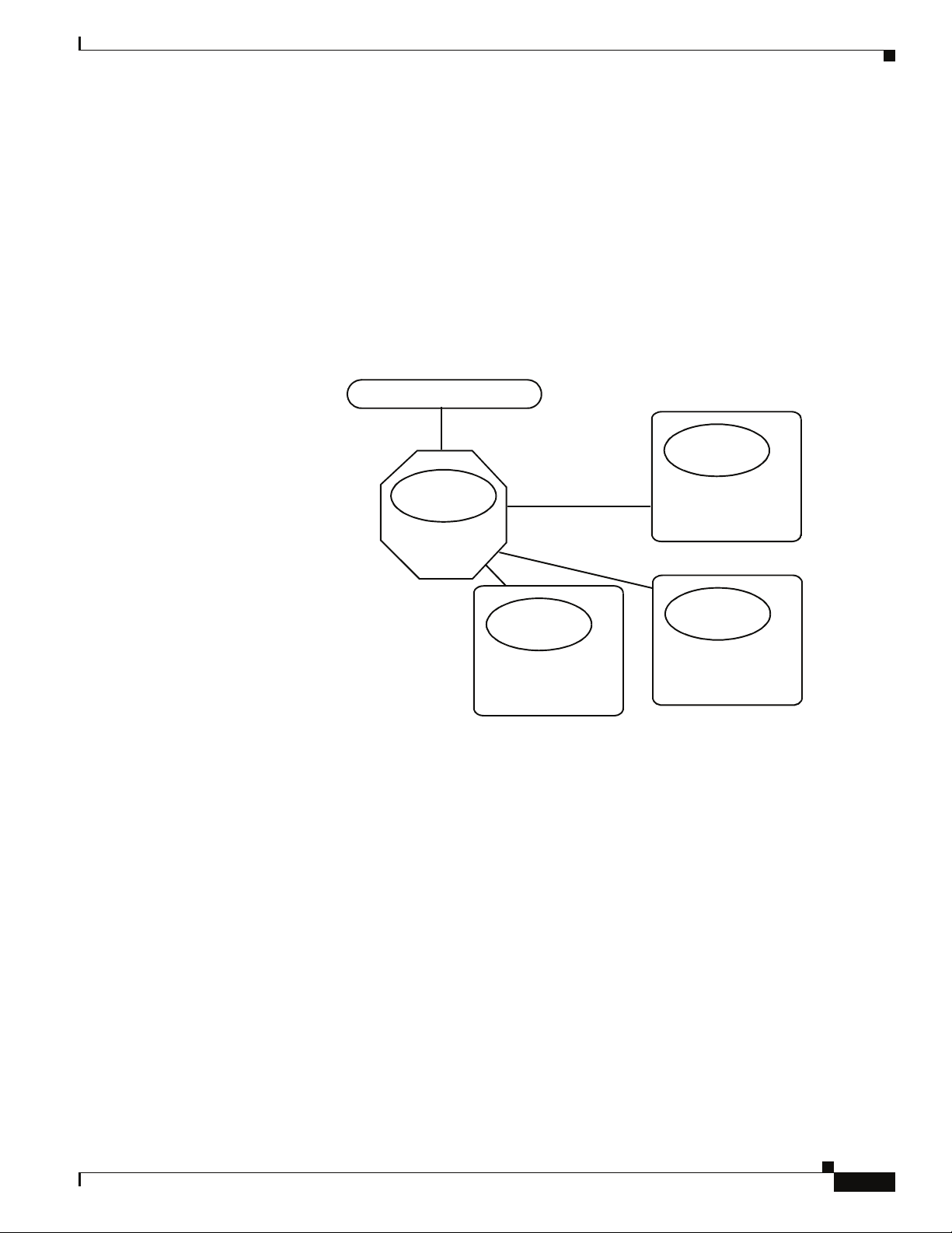
Every InfiniBand fabric subnet requires a single active Subnet Manager (SM) to initialize and maintain
the subnet. The fabric may also have one or more standby Subnet Managers. One of the standby Subnet
Managers can be configured to become the active SM in the event of a failure.
As Figure 1-2 shows, InfiniBand-enabled fabrics consist of one or more subnets. Each subnet consists
of a number of InfiniBand-capable servers connected to target devices. InfiniBand-capable routers
provide connectivity between InfiniBand subnets.
Figure 1-2 Subnet Manager
–
Reset the logs
–
Perform maintenance tasks
–
Manage firmware updates, including uploading new firmware and setting the active version.
InfiniBand
Subnet Manager
for Subnet A
SFS 7024
Subnet A
Chapter
InfiniBand
IB Port
Subnet Manager
Router
for Subnet B
IB Port
IB Port
Router
IB Port
Subnet B
IB Port
IB Port
InfiniBand
Capable Server
HCA
IB Port
IB Port
InfiniBand
HCA
Capable Server
When a network is initially powered up, the Subnet Manager queries the subnet management agents
running on the network devices, for information about node/port addressing schemes, routing tables and
partitions. From that point on, the Subnet Manager periodically sweeps the network for changes. Once
the InfiniBand network is up and running, the InfiniBand General Services Managers (GSMs) begin to
interface with General Services Agents (GSAs).
1-4
Cisco SFS 7024 Hardware Users Guide
OL-8794-02
Chapter
Subnet Management
Subnet Management Agents
A Subnet Management Agent processes management requests from the Subnet Manager. Subnet
Management Agents are implemented on all nodes within the InfiniBand fabric. These nodes include
IB-capable switches, routers, and channel adapters. Each node implements a Subnet Management Agent.
Within the SFS 7024 Switch, a Subnet Management Agent (SMA) is implemented within its firmware.
An SMA also runs on every InfiniBand-capable server that is equipped with an HCA. As shown in
Figure 1-3 the Subnet Manager interacts with these SMAs to discover information about the nodes on
the fabric.
Figure 1-3 InfiniBand Managers and Agents
Subnet Manager
Subnet
Management
Agent
SFS
7024
Subnet
Management
Agent
InfiniBand
Capable Server
The Subnet Manager utilizes the agent information to discover and manage connections from the SFS
7024 to the InfiniBand fabric. The Subnet Manager maintains a database tracking subnet topology
information as a result of its interaction with the SMAs.
InfiniBand General Services Managers and Agents
The InfiniBand specification defines the InfiniBand General Services Managers and their associated
agents. General Services Managers exchange messages with agents to manage and monitor the
performance and the physical environment of devices on the network.
Once the InfiniBand network is up and running, the InfiniBand General Services Managers begin to
interface with General Services Agents. The General Services Managers and Agents include:
• Subnet Administration (SA)
SA provides InfiniBand fabric nodes with an interface to the Subnet Manager. This interface is used
by the nodes on the fabric to interact with the Master Subnet Manager and to discover information
about the fabric. Every InfiniBand fabric subnet requires a SA.
• The Device Manager (DM) and Device Management Agent (DMA)
Subnet
Management
Agent
InfiniBand
Capable Server
Subnet
Management
Agent
InfiniBand
Capable Server
OL-8794-02
The DM and DMA discover and manage the association between hosts and devices behind the Target
Channel Adapters.
Cisco SFS 7024 Hardware Users Guide
1-5

SNMP Support
Chapter
• The Communications Manager (CM)
The CM establishes and manages communication channels between nodes.
• The Baseboard Manager (BM) and Baseboard Management Agent (BMA)
The BM and BMA exchange messages relating to items such as temperature monitoring and
hardware control to manage hardware on the fabric.
• The Performance Manager (PM) and Performance Management Agent (PMA)
The PM and PMA exchange messages about performance statistics and error information of
InfiniBand devices on the fabric.
Built-in support for Simple Network Management Protocol (SNMP) allows users to integrate a SFS 7024
into their existing management frameworks. SNMP allows users access to all statistics, trend analysis,
alarm handling, filtering, and performance monitoring capabilities supported by these management
frameworks.
SNMP MIBs
SNMP Management Information Bases (MIBs) are management elements that are used by industry
frameworks to monitor information about the SFS 7024 switch. The SFS 7024 switch supports MIBs
from the following sources:
• Switch-sourced MIBs: MIBs from the CMU of the SFS 7024 provide status information regarding
the physical environment of the switch. Additionally, the CMU MIBs provide status and activity
information for all line cards residing in the switch.
1-6
Cisco SFS 7024 Hardware Users Guide
OL-8794-02

CHAPTER
Installation
This chapter describes how to install the Cisco SFS 7024™ and its components, and it includes the
following information:
• Planning the Installation, page 2-8
• Installation Tasks, page 2-15
• Hot Swapping Components, page 2-31
Note Before you install, operate, or service the system, read the Regulatory Compliance and Safety
Information for the Cisco SFS 7012 and SFS 7024 for important safety information.
2
OL-8794-02
Cisco SFS 7024 Hardware Users Guide
2-7
Chapter
Warning
Warning
Warning
Warning
IMPORTANT SAFETY INSTRUCTIONS
This warning symbol means danger. You are in a situation that could cause bodily injury. Before you
work on any equipment, be aware of the hazards involved with electrical circuitry and be familiar
with standard practices for preventing accidents. Use the statement number provided at the end of
each warning to locate its translation in the translated safety warnings that accompanied this device.
Statement 1071
SAVE THESE INSTRUCTIONS
This unit is intended for installation in restricted access areas. A restricted access area can be
accessed only through the use of a special tool, lock and key, or other means of security.
Statement 1017
Only trained and qualified personnel should be allowed to install, replace, or service this equipment.
Statement 1030
A readily accessible two-poled disconnect device must be incorporated in the fixed wiring.
1022
Statement
Planning the Installation
Environmental Requirements
To assure proper operation and avoid unnecessary maintenance, the installation site must conform to
certain environmental specifications.
Figure 2-1 Environmental Requirements
Ambient operating
temperature
Non-operating temperature -35°C to 65°C
Airflow requirements Air flows into the switch from front to back.
Humidity 5% to 85% relative humidity (noncondensing).
41° - 113°F (5° - 45°C)
Cabinet doors must not impede the front-to-back
air flow.
Power supplies use the air inside the chassis and
exhaust out the front of the chassis.
2-8
Cisco SFS 7024 Hardware Users Guide
OL-8794-02
Chapter
Rack Specifications and Recommendations
The SFS 7024 switch is designed to be installed in an existing 19-inch equipment rack or server rack.
The SFS 7024 switch is designed for a four-post server cabinet. It is not designed for a two-post telco
cabinet.
Racks should conform to conventional standards. In the United States, use American National Standards
Institute (ANSI)/Electronic Industries Association (EIA) standard ANSI/EIA-310-D-92, and
International Electrotechnical Commission (IEC) 297
• Racks should meet the following mechanical recommendations:
–
Four-post, 19" rack to facilitate easy maintenance
–
Universal mounting rail hole pattern identified in IEC Standard 297
–
Mounting holes flush with the rails to accommodate the switch
• Use a rack grounding kit and a ground conductor that is carried back to earth or to another suitable
building ground. Ground the equipment rack to earth ground.
• Provide enough room to work on the equipment. Clear the work site of any unnecessary materials.
Make sure the equipment will have enough clearance for front and rear access.
Installing and Routing Cable
Note Building and electrical codes vary depending on the location. Comply with all code specifications when
planning the site and installing cable.
When running cables to the equipment, consider the following:
• Do not run cables where they can be stepped on or rolled over.
• Be sure cables are intact with no cuts, bends, or nicks.
• Provide proper strain relief for standard IB cables by adhering to the following guidelines:
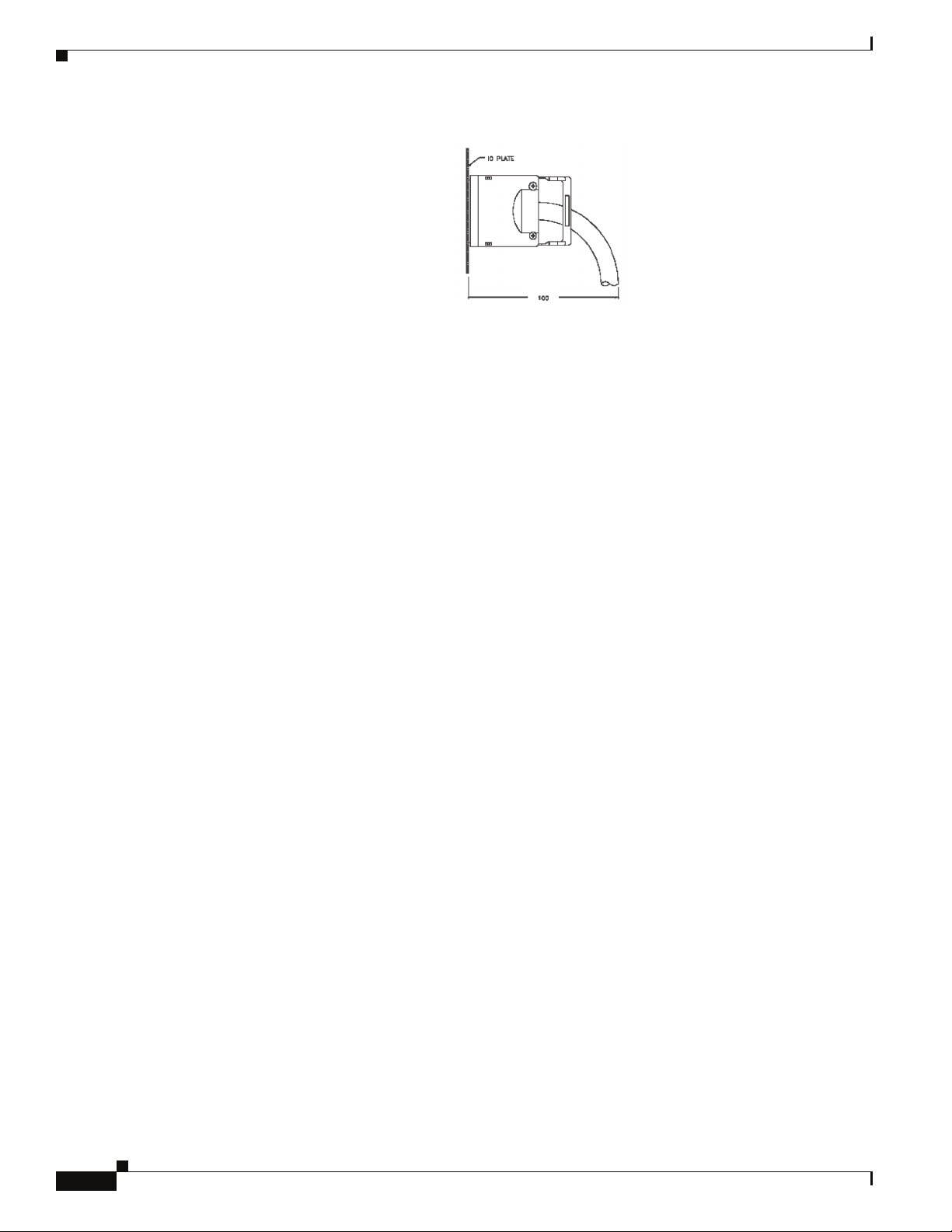
Figure 2-2 Cable Bend Radii
Assembly 90-Degree Bend Radii
American Wire Gauge (AWG) Size
Cable
24 5.20 inches
26 4.80 inches
28 4.70 inches
• Temporary 90-degree bend can never be more than 0.5 inches tighter than the values listed above for
any assembly.
4X Bend Radius
OL-8794-02
• This is the absolute minimum sustained bend radius for each 4X cable AWG size. This measurement
is the distance from the panel to the point where the cable makes a 90-degree bend. In other words,
this number includes the 2" connector stand-off from the panel surface.
Cisco SFS 7024 Hardware Users Guide
2-9
Chapter
Figure 2-3 Bend Radius Measurement Diagram
• Support cable using a cable manager mounted above connectors to avoid unnecessary weight on the
cable bundles.
• Bundle cables using velcro straps to avoid damaging cables.
• Keep all ports and connectors free of dust.
• Unshielded Twisted Pair (UTP) cables can build up Electrostatic Discharge (ESD) charges when
being pulled into a new installation. Before installing category 5 UTP cables, discharge ESD from
the cable by plugging it into a port on a system that is not powered on.
• When required for safety and fire rating requirements, plenum-rated cable can be used. Check the
local building codes to determine when it is appropriate to use plenum-rated cable, or refer to IEC
standard 850.
Power Requirements
Power Supply
• The switch power supplies have a maximum power consumption requirement of 350W. Also ensure
that the site meets all power supply requirements.
• Before installation and periodically after installation, check that the site is receiving clean power.
Install a power conditioner if necessary.
• Be sure the site is properly grounded to avoid damage from lightning and power surges.
Uninterruptible Power Supply
Consider the following when selecting Uninterruptible Power Supply (UPS) equipment:
• The minimum amperage requirements for a UPS:
–
–
• Transition time (the time necessary for the UPS to transfer from utility power to full-load battery
power).
• The longest potential time period the UPS might be required to supply backup power.
• Whether or not the UPS unit also provides online protection.
Calculate VA (Volt-Amps): Locate the voltage and amperage requirements for each piece of
equipment (usually located on a sticker on the back or bottom of the equipment). Multiply the
numbers together to get VA.
Add the VA from each piece of equipment together to find the total VA requirement. Then add
30% to determine the minimum amperage requirements for the UPS.
2-10
Cisco SFS 7024 Hardware Users Guide
OL-8794-02
Chapter
Installation Tasks Checklist
To perform the actual switch installation, the site implementation engineer must perform the following
tasks, which are detailed in this section.
Caution Be sure to review the Safety Information on page 11 before starting the installation and during the
installation process.
Step 1 Check the installation site to verify the installation of cabinet power feeds, rails, and grounding.
Step 2 Unpack the equipment and inspect for any shipping damage. Any shipping damage should be reported
to the shipping company.
Step 3 Verify that the equipment serial numbers match those on the packing slip.
Step 4 Mark the rack and install the mounting rails.
Step 5 Physically install the switch in the rack.
Step 6 Install IB cables between the SFS 7012 and other IB-enabled network devices.
Step 7 Install intra-cabinet power and grounding cables for the switch.
Step 8 Power up the switch.
Step 9 Verify the default system IP address for each hemisphere (192.168.100.9)
Step 10 Add the equipment to the network.
Safety Information
Note A textual callout designed to emphasize:
Caution Potential for damage to system equipment. Damage to the system caused by the user may have potential
The following safety guidelines are provided to ensure both personal safety for the user and to protect
the system from potential damage. These precautions cover the following categories:
• Precautions for Rack-Mountable Products
• Protecting Against Electrostatic Discharge
• Electrical Safety Precautions
Precautions fit into one of three categories:
–
Tasks of particular importance.
–
Tips and reminders to maximize the use of the equipment.
warranty implications.
OL-8794-02
Warning
Potential for personal injury.
Cisco SFS 7024 Hardware Users Guide
2-11
Precautions for Rack-Mountable Products
Chapter
Warning
Installing system components in a rack without the front and side stabilizers installed could cause
the rack to tip over. Therefore, always install the stabilizers before installing components in the rack.
Warning
After installing system components in a rack never pull more than one component at one time out of
the rack on its slide assemblies. The weight of more than one extended component could cause the
rack to tip over.
Warning
Warning
Do not step on or stand on any component when servicing other components in a rack.
The chassis, when fully populated with leaf modules, spine modules, power and fan supplies, is very
heavy (approximately 175 lbs.). It is recommended that a lifting device be used to handle a fully loaded
chassis.
Caution Always load the rack from the bottom up, loading the heaviest item first.
Caution Make sure the rack is level and stable before extending any component from the rack.
Note Ensure that proper airflow is provided to components of the rack.
Protecting Against Electrostatic Discharge
Caution Use a grounded wrist strap designed to prevent static discharge.
Caution Static electricity can harm delicate components inside the system. To prevent ESD damage, users need
discharge any static electricity from their bodies before touching any electronic components. Touching
an unpainted metal surface will discharge static electricity.
Caution When transporting an ESD sensitive component, first place it in an antistatic container or packaging.
Electrical Safety Precautions
Warning
Do not work alone when working with high voltage components.
2-12
Cisco SFS 7024 Hardware Users Guide
OL-8794-02
Chapter
Warning
This unit may have more than one power cord. To reduce the risk of electrical shock, disconnect both
cords before servicing the unit.
Warning
Warning
Warning
To avoid potential electrical shock, operate this unit only when the cover is in place.
To avoid potential electrical shock, use only a grounded (three wire) electrical outlet.
Keep objects that might damage this unit and liquids that might spill clear from this unit. Liquids and
foreign objects that come into contact with voltage points could create the risk of fire or electrical
shock.
Caution Do not overload the power supply branch circuit providing power to the rack. The total rack load should
not exceed 80 percent of the branch circuit rating.
Caution Keep power cord and connection cables clear of obstructions that might cause damage.
Caution Do not attempt to service the unit yourself. The first course of action is to contact Technical Support.
Note Unplug this unit from the electrical outlet and refer servicing to a qualified service center if any of the
following conditions occur:
–
The power cord is damaged or frayed.
–
The unit has been dropped or the case has been damaged.
–
The unit has been exposed to any liquids.
–
The unit does not operate normally when all operating instructions have been followed.
–
The unit exhibits a distinct change in performance, indicating a need for service.
Tools and Equipment Required
• An ESD wrist strap
• A #2 Phillips screwdriver
• Pen (felt-tip) to mark the mounting holes
OL-8794-02
Cisco SFS 7024 Hardware Users Guide
2-13

Check the Installation Site
The SFS 7024 switch is designed to be installed in an existing server cabinet (not a telco cabinet), where
it can be mounted in a standard equipment rack. Mounting brackets are integrated with the switch.
Be sure of the following:
• The cabinet has a full earth ground to provide reliable grounding.
• There is enough room to work on the equipment.
• The equipment will have enough clearance for front and rear access.
• The IB cables can be accessed easily.
• Water or moisture cannot enter the switch.
• The ambient temperature stays between 50° - 113°F (10° - 45° C).
• Cabinet doors do not interfere with front-to-back air flow.
The cabinet should have its own power distribution (with switch). If the switch has two power supplies,
it is suggested that a cabinet with dual power distribution units is used.
It is recommended that cabinet anti-tip devices are used. This is especially true if installing or removing
an SFS 7024 switch in the upper half of the cabinet when the lower half is empty.
Chapter
Unpack the Equipment
Warning
Step 1 Carefully open the box and unpack the SFS 7024 switch. The SFS 7024 is shipped fully populated and
Step 2 Inspect the equipment for any shipping damage and report any problems to the shipping company.
Read all installation instructions before connecting the system to its power source.
should contain.
–
–
–
–
–
–
–
–
–
SFS 7024 Chassis
Leaf modules (up to 24)
Leaf module blanks (up to 23). These blanks populate unused leaf module slots to help maintain
the thermal integrity of the chassis.
Spine modules (up to 6)
Spine module blanks (up to 4). These blanks populate unused spine module slots to help
maintain the thermal integrity of the chassis.
Power Supplies: up to twelve (12)
Power supply blanks (up to 6). These blanks populate unused power supply slots to help
maintain the thermal integrity of the chassis.
Fans (8)
Mounting hardware kits
2-14
Step 3 Verify that the equipment serial numbers match those on the packing slip.
Step 4 Resolve any issues with incorrect serial numbers or missing/incorrect parts before installing the
equipment.
Cisco SFS 7024 Hardware Users Guide
OL-8794-02
 Loading...