

Page 1
B A L A N C I N G M A C H I N E S
Transmitter
Vibrations transmitter
TR-A/TR-V
B A L A N C I N G M A C H I N E S
Page 2
TR-A/TR-V
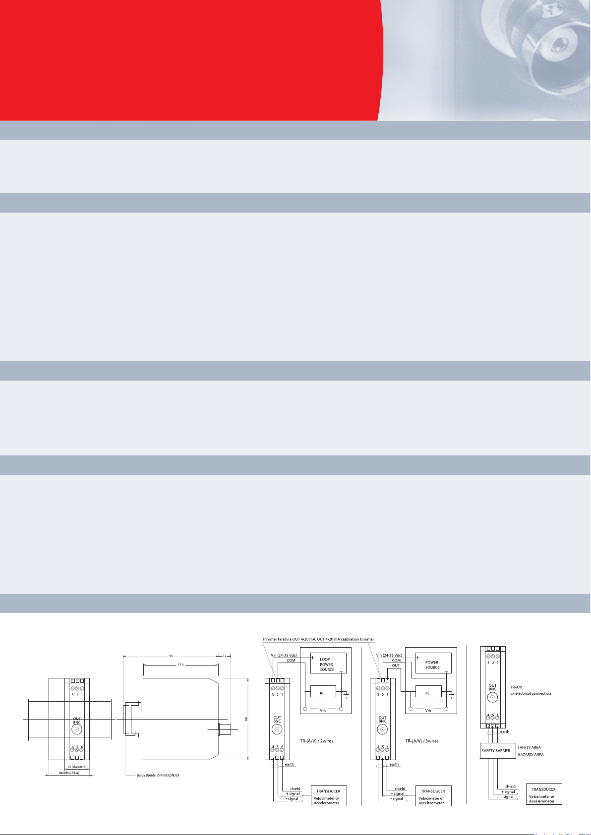
The TR-A and TR-V transmitters can be installed directly in the field inside an IP65 container (junction box) or on the rear of
the panel inside an electric control panel. We recommend you use this connection method whenever you want to monitor
machines situated in classified areas (in the chemicals or petroleum industries), using intrinsecally safe transducers that
interface with the transmitters installed in the safe area via a Zener barrier situated near the transmitter.
Main features
• type of transducer (velocimeter or accelerometer)
• dimension measured (displacement, velocity, acceleration)
• means of detection (RMS, peak, peak-to-peak)
• measuring range
• high pass filter
• low pass filter
• two or three wire power supply
Presettings possible when ordering
The TR-A and TR-V transmitters measure the absolute vibration of the pedestal of any rotating machine capable of interfacing
directly with a two-wire technique acquisition system (4-20 mA current loop) or a three-wire technique acquisition system (24
V DC power supply).
Function
The need to monitor an increasing number of machines at a reasonable cost, especially in large plants, calls for compact
systems that are easy to install and interface with the centralized data acquisition system. The TR-A and TR-V transmitters
minimize the proportion of the installation and cabling costs, which normally limits the possibilities of applying conventional
vibration monitoring systems.
These transmitters acquire the signal of a velocimeter or an accelerometer and convert it into a signal in current (4-20 mA) proportional
respectively to the displacement or to the velocity of the vibration in the first case and to the velocity or to the acceleration of the vibration in
the second case. The transmitter is connected to the sensor (veloc imeter or accelerometer) via a shielded bipolar cable (2x1 mm2).
The transmitter is connected to the acquisition system via a bipolar cable (2x1 mm2) or a tripolar cable (3x1 mm2).
A BNC socket can be used to connect a spectrum analyser so that the signal can be analysed and the machine being monitored can
be diagnosed.
Typical applications
Overall dimensions, installation and elettrical connection
Page 3

G : 3 wire power supply
F : 1000 Hz low pass filter
E : 10 Hz high pass filter
D : measuring range 0÷10 mm/s
C : RMS detection
B : velocity detection
A : accelerometer
Example of order:
A / B / C / D / E / F / G
TR -
A / B / C / D / E / F / G
TR -
A : type of transducer
V velocimeter
A accelerometer
B : dimension measured
0 displacement
(TR-V only)
1 velocity
2 acceleration
(TR-A only)
C : means of detection
0 RMS
1 peak
2 peak-to-peak
D : measuring range
0 0 ÷ 100 µm 6 0 ÷ 1 g
1 0 ÷ 200 µm 7 0 ÷ 5 g
2 0 ÷ 500 µm 8 0 ÷ 10 g
3 0 ÷ 10 mm/s 9 0 ÷ 20 g
4 0 ÷ 20 mm/s S
special to be defined
5 0 ÷ 50 mm/s
F : low pass filter
0 no filter
1 100 Hz
2 1000 Hz
3 2500 Hz
4 5000 Hz
5 10000 Hz
S special to be defined
N.B. : the frequency of the
low pass filter must be at least
double than that of the high
pass filter.
G : type of power supply
2 2 wires (current loop)
3 3 wires
E : high pass filter
0 no filter 4 50 Hz
1 5 Hz 5 100 Hz
2 10 Hz 6 1000 Hz
3 20 Hz S
special to be defined
B A L A N C I N G M A C H I N E S
Information necessary for ordering
A 1 0
3
2 2 3
Page 4

Composition:
• Transmitter suitable to be fitted on DIN guide rails
TR-V model interfaceable with velocimeter
TR-A model interfaceable with preamplified accelerometer
Usable transducers:
• velocimeters sensibility 21.2 mV/mm/sec
T1-40 – T1-40V – T1-40BF – T1-38 – T1-38V – T1-38BF
• accelerometer sensibility 100 mV/g
TA-18 – TA-18/S
Power supplies:
• 24 Vdc nominal (24 – 35 Vdc), 4 ÷ 20 mA current loop
(2 or 3 wire)
External connections:
• terminal board for connecting transducer to acquisition system
(max cable section 2,5 mm2)
• BNC connector for connecting to analyser
Environmental range of use:
• -10° C ÷ + 70° C
Technical data
All the data and features mentioned in this catalogue are purely for information and do not
constitute any commitment on the part of our company, which reserves the right to make any and
all alterations it may consider suitable without notice.
CEMB S.p.A.
Via Risorgimento, 9
23826 Mandello del Lario (LC) Italy
www.cemb.com
Vibration analysis division:
phone +39 0341 706111
fax +39 0341 706299
e-mail: stm@cemb.com
B A L A N C I N G M A C H I N E S
AT 500 1020 06/08
 Loading...