

Page 1
CEMB S.p.A. - 23826 MANDELLO DEL LARIO (LC) ITALY - Via Risorgimento 9
Phone +39 0341 706111 - Fax +39 0341 706299
www.cemb.com e-mail: stm@cemb.com
----------------------------------------------------------------------------------------------------------------------
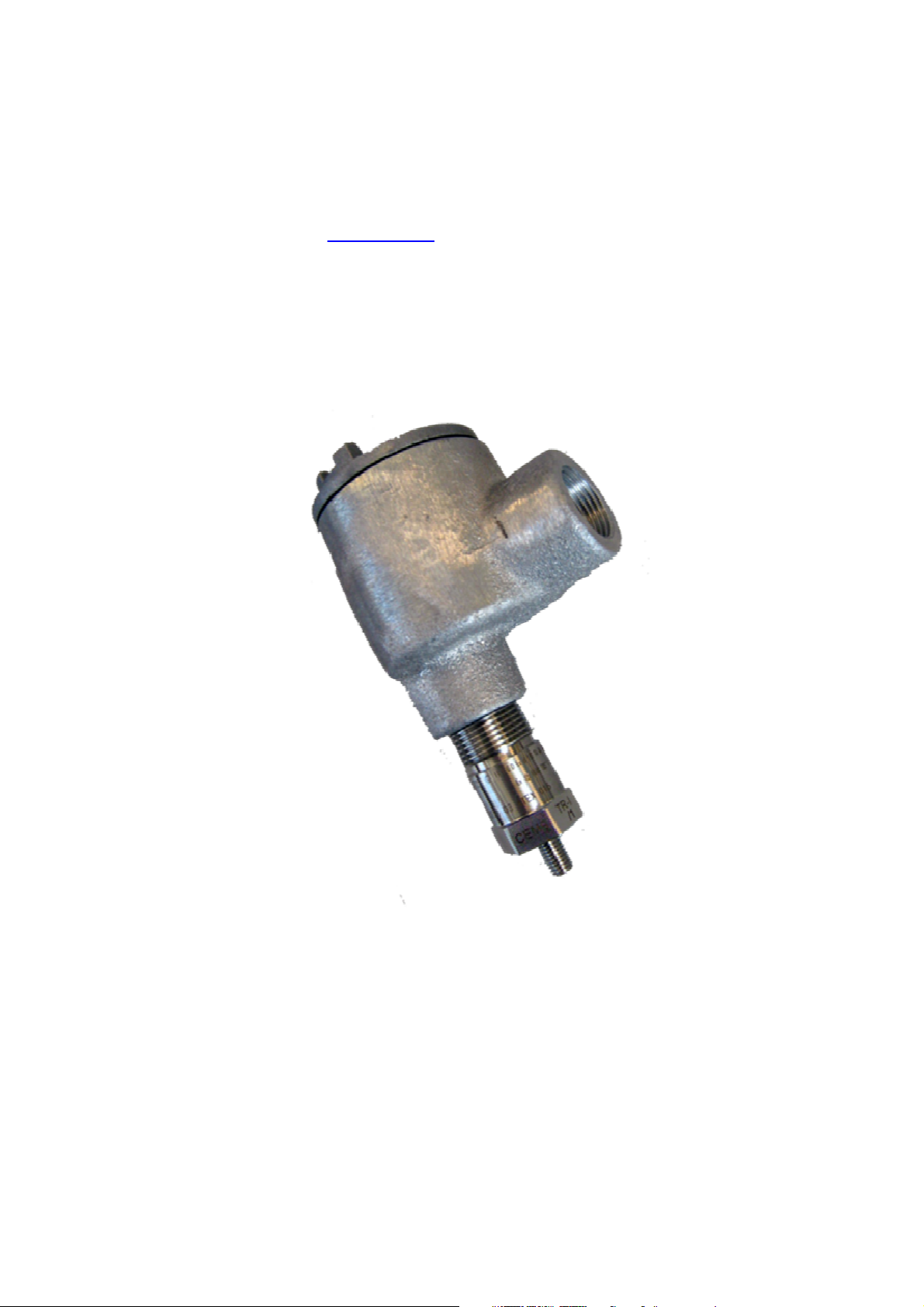
VIBRATION TRANSMITTER model TR–I/ATEX
Certified according to ATEX 94/9/CE Directive
Function
TR-I integrated transmitter measures absolute vibrations in the hazardous area of the support of
any rotating machine and it can be interfaced directly by 2-wire technique (current loop 4÷20 mA)
to an acquisition system (PLC or DCS).
TR-I minimizes the incidence of installation and wiring which could normally limit the application
possibilities of traditional vibration monitoring systems.
The transmitter is certified for application in classified area as II 2GD Ex d IIC T6 Gb
Ex tb IIIC T85°C Db
Page 2

General description
The transmitter, fixed directly on the machinery, generates a current signal (4÷20 mA) proportional
respectively to the vibration speed or to the vibration acceleration.
It consists of a stainless steel body with male thread machine connection ¼” 18 NPT and a die-cast
aluminium casing for the terminal board with female thread connection ¾” NPT.
It can be supplied complete with mechanical accessories for machine connection threads different
from those proposed as standard.
Note: The transmitter is duly calibrated at CEMB laboratory according to the customer’s
indications. It is not possible to perform further recalibration later on. The transmitter is ready after
the correct calibration as shown on dwg 99564-P here enclosed and it does not need adjustments
or maintenance.
Principle of operation
A suitable accelerometer, inside the transmitter body, produces a voltage signal proportional to the
vibration acceleration. This signal is appropriately conditioned by an electronic circuit ( placed inside
the transmitter body) and converted into a 4÷20 mA current signal proportional to the vibration.
Technical characteristics
Power supply
• 24 Vdc (10 ÷ 30 Vdc) current loop 4 ÷ 20 mA (2 wires)
• Maximum load: see picture 2
Dynamic performances
• ±3% / 10Hz-1kHz (see picture 1)
• -3db / 2Hz – 2.5kHz
Environmental operating range
• - 40°C ÷ + 70°C
• IP 65 EN 60529/10.91 standards (with external connections protected by an adequate
sheath with ¾”14NPT thread, as per dwg. 96564-P)
Type of measurement
• Seismic omnidirectional (absolute vibration)
Dynamic range
• ± 18 g-pk / 2 ÷ 2500 Hz
2
Page 3

Transversal sensitivity
• < 5 %
Linearity
• ± 2% F.S. - 75 Hz
Outer casing (see enclosed dwg.99564-P)
• Stainless steel AISI 316L integrated transmitter body
• Aluminium Atex certified housing ( ¾”14NPT threads)
Insulation
• ≥ 10
8
Ω between signal and box
Axis of application
• any
Threads
• ¼”18NPT male
• M8x1,25 male
Mounting torque
• 5÷10 Nm
Maintenance
• none
Electrical connections
Bipolar schielded cable, section of the conductors:
• 2x1 mm² until 200 m
• 2x1,5 mm² until 400 m
• 2x2,5 mm² until 800 m
Possible arrangements when placing the order
• Measuring range
• Type of thread connection
Reference standards:
. EN 60079-0 (2009): Explosive atmosphere - General Rules
. EN 60079-1 (2007): Explosive proof housings “d”
. EN 60079-31 (2009): Equipments for combustible dust Part 31: protection by means of
housings “t”
3
Page 4

Picture 1 – Frequency response [db]
900
Power supply [V]
Picture 2 – Maximum permissible load on current loop
800
700
600
500
400
300
Maximum load [Ohm]
200
100
0
0 5 10 15 20 25 30 35
4
Page 5

Notes concerning certification:
1) The employ of Atex certified transmitters is not allowed for different hazardous conditions or
anyway those exceeding the data specified on the label of the transmitter itself.
2) The transmitter does not require maintenance. Any work regarding performance checks or
repair should only be carried out in a laboratory duly authorized by CEMB SpA.
Ordering information
A B
TR – I / /
where
A : measuring range
0 0 ÷ 10 mm/s RMS
1 0 ÷ 20 mm/s RMS
2 0 ÷ 50 mm/s RMS
3 0 ÷ 100 mm/s RMS
4 0 ÷ 1 g RMS
5 0 ÷ 5 g RMS
6 0 ÷ 10 g RMS
S special to be defined
B : thread connections
0 standard ¼”18NPT
1 M8 x 1,25
Example of order
TR – I / 0 / 1
0 = measuring range 0÷10 mm/s RMS
1 = thread connection M8x1,25
5
Page 6

Certification according to ATEX 94/9/CE
0722 II 2GD Ex d IIC T6 Gb
Ex tb IIIC T85°Db
CESI 03 ATEX 016
Legend of nameplate safety data
0722 Number of the Notified Body carrying out the surveillance (CESI)
II
2
G Protection for Gases, Vapours, Mists
D Protection for Dusts
Ex d Equipment belonging to gas explosion proof category "d"
II C
T6
Marking of conformity to the applicable European directives
Marking of conformity to 94/9/CE Directive and relevant technical
standards
Equipment suitable for surface applications
(not for mining)
Equipment intended for use in areas in which explosive
atmosphere caused by mixtures of air and gases, vapours, mists
or air/dust mixtures are likely to occur, high level of protection.
suitable for Zone 1 and 21
Suitable for substances (gases) of group IIC, also suitable for
groups IIA e IIB
Class of surface temperature suitable for the corresponding
temperature class of the flammable substance
(T6 = maximum surface temperature 85°C)
CESI 03 ATEX 016
6
Gb High level of protection for gas
Ex tb
IIIC Equipment for conducting and non conducting combustible dust
T85°C Maximum surface temperature
Db High level of protection for dust
Tamb
Equipment for use in the presence of combustible dust with
• Name of the laboratory issuing the CE-type-examination
certificate
• 03 = year of issuing the certificate
• 016 = number of certificate
protection by means of tight housing
Certificate identification:
Ambient temperature –40°C ÷ 70 °C
Page 7

TR-I-ATEX 05 gb ASTM 22520
7
 Loading...