

Page 1

----------------------------------------------------------------------------------------------------------------------
VIBRATIONS TRANSMITTER mod. Ex TR-26
Function
The integrated transmitter mod. Ex TR-26 measures the Absolute Vibrations of any rotating
machine support and is able to interface itself directly (two-wires technique, current loop 4 to 20
mA) with an acquisition system (PLC or DCS).
The transmitter reduces at maximum installation and wiring incidence, that normally limits the
possibilities to apply the traditional systems for vibration monitoring.
The transmitter is certified for applications in areas classified as:
- Ex II 2 G Ex ia IIC T6 or T5 or T4
General description
The transmitter, assembled through direct fastening on the machinery, generates a current signal (4
to 20 mA) that is proportional respectively to vibration speed or acceleration.
The transmitter is composed of a stainless steel body having a threaded machine connection; the
connection with the users is performed bymeans of a MIL-C-5015 connector (2 poles), included.
NOTE: The transmitter is available in different configurations and becomes operative only after its
correct electrical connection, as per drawing no. 85465-P; it doesn’t need setup or maintenance.
Technical characteristics
Page 2

Composition
Integrated transmitter body, in AISI 316L stainless steel material.
Power supply
24 Vdc (10 to 35 Vdc) current loop 4 to 20 mA (two-wires)
Maximum load as per figure 2
External connections
MIL-C-5015, 2 poles connector (conductors max section 2,5 mm²)
Environmental use field
- 50°C to + 120°C
IP 65 EN 60529/10.91 standards
Measurement type
Omnidirectional seismic (absolute vibrations)
Dynamic field
± 18 g
Transversal sensitivity
< 5 %
Linearity
± 2% - 75 Hz
Dynamic performances
±3% / 10Hz-1kHz (See figure 1)
-3db / 1.5Hz – 2.5kHz
Insulation
108 between signal and container
Application axis
any
Process standard connections
M8x1,25
¼”-18NPT
¼’’-28UNF
Maintenance
none
Electrical connections
bipolar shielded cable, typical conductors section 2x1mm²
Possible prearrangements to the order
measuring field
fastening
ATEX certification type
Figure 1 – Frequency response [db]
2
Page 3
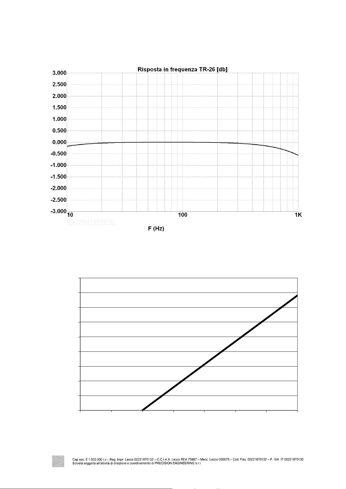
Figure 2 – Maximum allowable load on current loop
900
Power supply [V]
800
700
600
500
400
300
Maximum load [Ohm]
200
100
0
0 5 10 15 20 25 30 35
3
Page 4

ASSEMBLY
N.B.: the operations must be performed, if possible, when the machine is OFF andby using the
maximum delicateness in order to avoid any transmitter damages.
1) Predispose a special threaded hole on the support to be measured. The surface on which the
transmitter lies must be flat and smooth. It is better to interpose a silicon layer between the
transducer and the support surface.
N.B. : Avoid giving violent shocks to the transmitter body, the closure torque must be 5 to
10 N-m.
2) Connect electrically the transmitter to the measuring equipment through the movable connector
(included).
Notes for connection:
- The wiring MUST be made by using a cable, resistant to working environment agents (oils,
corrosive acids, temperatures, etc.).
- A shielded cable MUST BE used, bearing in mind that the screen must be connected to the
frame mass (GND=ground) at only one of the two cable ends (recommended instrumentation
side).
Notes for certification:
- The use of ATEX certified transmitters is not allowed for different hazardous conditions or
for those exceeding the data specified on the nameplate affixed to the transmitter.
- The transmitter does not require maintenance. Any work regarding performance checks or
repair should only be carried out in a laboratory duly authorized byCEMB S.p.A.
4
Page 5

Notes for identification:
The transmitter is constructed to be correctly used, according to the conditions set out by the
following table:
Certifications to ATEX 94/9/CE
0722 II 2 G Ex ia IIC T4
0722 II 2 G Ex ia IIC T5
0722 II 2 G Ex ia IIC T6
CESI 09 ATEX 045
Legend of nameplate safety data
Marking of conformity withthe applicable European directives
0722 Number of the Notified Body carrying out the surveillance (CESI)
Marking of conformity withDirective 94/9/CE
and relative technical standards
II Equipment suitable for surface applications (not for mining)
2
G Protection for gases, vapours, mists.
Ex ia Equipment belonging to category "ia" with instrinsic safety.
II C
T4
T5
T6
CESI 09 ATEX 045
Ta = 120°C (T4)
Ta = 90°C (T5)
Ta = 75°C (T6)
Equipment designed to environments in which explosive atmospheres
caused bygases, vapours, mists or mixtures of air and dust may occur, high
level of protection. Suitable for zone 1.
Suitable for substances (gases) of group IIC,
also suitable for groups IIA and IIB
Temperature class T4 (surface temperature 135°C)
Temperature class T5 (surface temperature 100°C)
Temperature class T6 (surface temperature 85°C)
Certificate identification:
Name of the laboratoryissuing the CE-type-examination certificate
09 = certificate issuing year
045 = certificate number
Ambient temperature –50 to +120 °C
Ambient temperature –50 to +90 °C
Ambient temperature –50 to +75 °C
5
Page 6

Ordering data
A B C
TR – 26 / / /
where,
A : measuring field
0 0 to 10 mm/s RMS
1 0 to 20 mm/s RMS
2 0 to 50 mm/s RMS
3 0 to 100 mm/s RMS
4 0 to 1 g RMS
5 0 to 5 g RMS
6 0 to 10 g RMS
S Special, to be defined
B : threaded connection
0 M8x1,25
1 ¼’’ – 18NPT
2 ¼’’ – 28UNF
C : ATEX certification
0 None
2 II 2 G Ex ia IIC T6 or T5 or T4 (Zone 1)
Ordering example
TR – 26 / 1 / 0 / 2
TR – 26 measuring field 0 to 20 mm/s RMS, connection M8x1,25, certification for Zone 1
6
Page 7

ASTM09120
Ex TR-26 05 gb
7
 Loading...