

Page 1
Systems
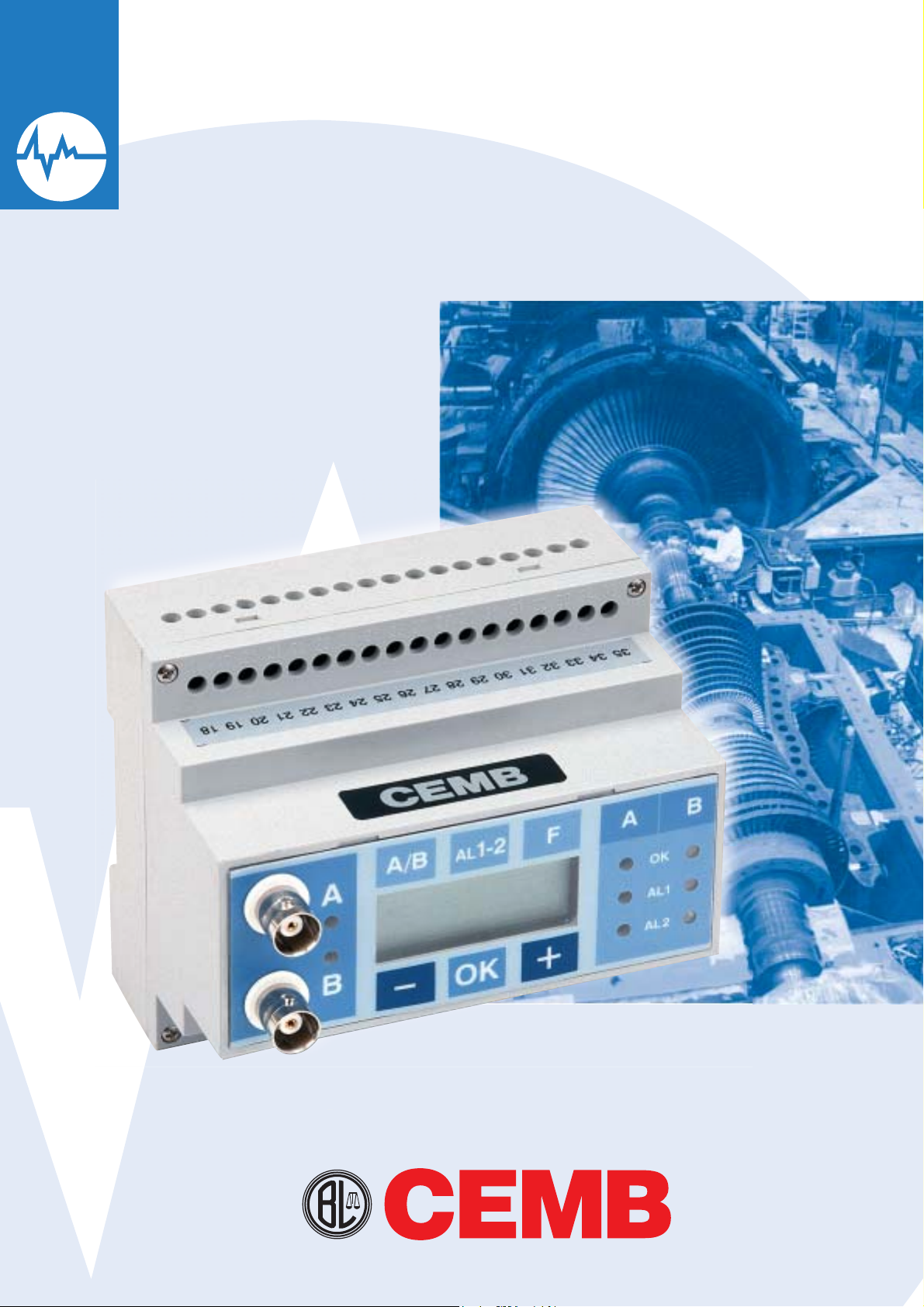
TM1
Vibration monitoring equipment, single/dual channel
BALANCING MACHINES
Page 2
Vibration monitoring equipment,
TM1
single/dual channel
Function
The TM1 equipment continuously measures the
vibrations of rotating machines by supplying analog
outputs (for interfaces to PLC or DCS) or digital
outputs (alarm and trip contacts) with the display on
a digital readout of the found value. The equipment
can be connected to other instruments (max. 32)
via serial line RS485 or to a PC (through appropriate
interface) for setting and reading the stored data by
the various measuring parameters.
Main characteristics
The TM1 instrument has been designed and
implemented with the latest digital technologies
which have allowed to improve the ß exibility
and performance of the system, by reducing its
overall dimensions and simplifying the procedures
for installation, setting and modiÞ cation of all the
operating parameters.
The instrument can be interfaced to 1 or 2 sensors
(velocity transducers or acceleration transducers)
besides with two phase reference transducers.
Digital readout of the vibration value allows the
operator to have an immediate check of the vibratory
state of the machine during set-up operations.
The control panel is provided with various buttons
Typical applications
Testing of the vibration of one or two channels
of any type of rotating machine (motors, fans,
compressors, turbines, pumps, etc.). It is normally
installed near the machine and performs all the
functions required for protection and monitoring:
measurement, protection, alarm signalling,
interfaceability with supervisory system, selfdiagnostics.
for presetting the operating parameters of
the instrument (selection of: measuring unit,
alarm thresholds, alarm time delay, threshold
multiplier, by-pass) as well as LED’s for displaying
the status regarding alarm, self-diagnostics
and BNC sockets for connection to a vibration
analyzer. The instrument is also provided with
a serial link RS485 for transferring stored data
and settings of all operating parameters of the
instrument by a PC.
The TM1 equipment can be installed in an
electrical cabinet (Þ xing on Din rail) or inside
a junction box positioned next to the machine
being monitored
.
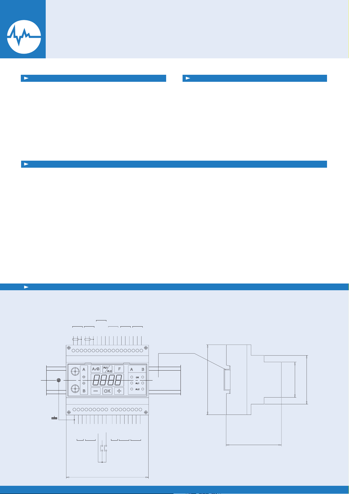
Connection wiring diagram and overall dimensions
OUTPUTS
TRANSD. Ch.A
SIG+
SIG+
SIG-
GND
GND
COM+
VDCin
GROUND
+24Vdc +/-10%
200 mA max.
POWER SUPPLY
ANALOG
TRANSD. Ch.B
SIG-
GND
OUT Ch.A
OUT Ch.B
sig+
sig+
sig-
GND
COM-
schield
BYP/RST
RS485
SPEED TRANSD.
GND
IDX A
IDX B
10 11 12 13 14 15 16 17987654321
CC
TRM
NO (NC)
RL5 (OK)
SELF DIA.
+24
CCNONC
AL1 Ch.B
RL3 1SPDT
CC
NC
NO
AL1 Ch.A
RL1 1SPDT
AL2 Ch.B
RL4 1SPDT
353433323130292827262524232221201918
CCNCNO
AL2 Ch.A
RL2 1SPDT
CCNCNO
NS35 EN50022
90
75
62
45
105
Page 3
Composition:
5
Inputs:
1 instrument in plastic box
1 or 2 measuring traducers (velocity or
acceleration transducer)
2 velocity transducers (optional)
Transducers which can be used:
Velocity transducers T1-40; T1-40V;
T1-40BF; T1-38: T1-38V; T1-38BF
Acceleration transducers (ICP) TA 18; M16; M602
Power supply:
24 Vdc nominal (22÷26 Vdc)
110/220 Vac 50 to 60 Hz (optional)
External connection:
Terminal board for connecting transducers
(max. cable section 2.5 mm2)
Terminal board for connecting alarm contacts
(max. cable section 2.5 mm2)
Terminal board for serial port RS485
BNC connectors for connection to the
analyzer
Ambient temperature range:
2 inputs, vibration transducers
2 inputs, velocity transducers
2 inputs for TRIP MULTIPLIER and
BYPASS/RESET
Serial link RS485
Analog outputs:
2 analog outputs 4:20 mA / 0: 10 V
Output relays:
SPDT contacts, I level, channel A/B
SPDT contacts, II level, channel A/B
SPDT contact, self-diagnostics
Max. measuring range:
velocity: 200 mm/s
acceleration: 50g
displacement: 1000 µm
Type of measurement:
RMS, peak, peak-to-peak
Protection degree:
-20° / +70°C
IP30 EN 529/10.91
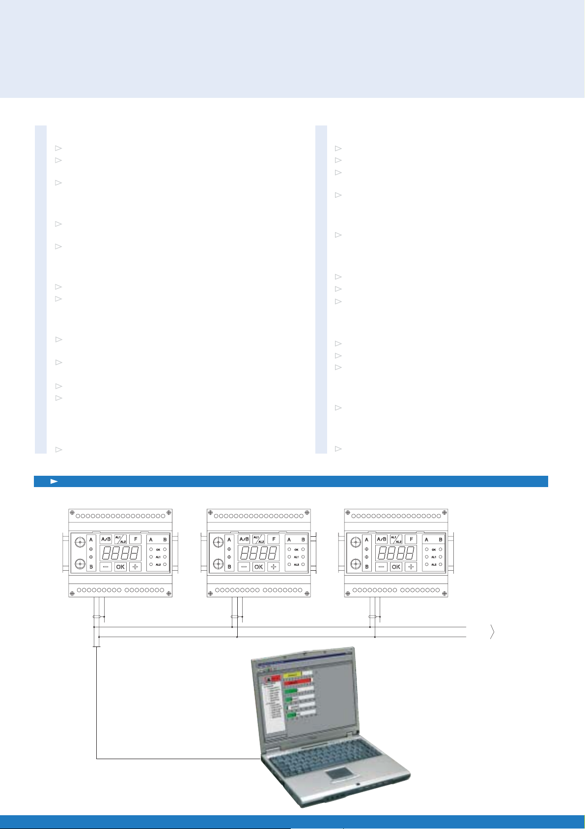
TM1: example of multiple application
TM1/1 TM1/2 TM1/3 .......... max. 32
10 11 12 13 14 15 16 17987654321
COM+
COM-
353433323130292827262524232221201918
123456789 10 1211 13 1514 16 17
COM+
COM-
272118 19 20 2422 23 25 26 333028 29 31 32 34 35
18 2019 21 2322 24 2625 27 2928 30 3231 33 3534
1 32 4 65 7 98 10 11 1312 14 1615 17
COM-
COM+
COM+
COM-
RS 48
Page 4

ORDER INFORMATION
The TM1 equipment is supplied according to the conÞ guration selected by the
Customer. However the setting of the operating parameters can be varied
during installation of the system by using the buttons on the control panel or
via serial link RS485 using a PC provided with the appropriate program.
/ A / B / C / D / E / F / G / H
TM1
//// ///
/
A: Type of transducer
V velocity transducer
A acceleration transducer
B: Dimension measured
0 displacement
1 velocity
2 acceleration
C:Mode of measurement
0 RMS
1 peak
2 peak-to-peak
D: Range of measurement
0 0: 100 µm
1 0: 200
2 0:
250
µm
µm
3 0: 10 mm/sec
4 0: 20 mm/sec
5 0: 50 mm/sec
6 0: 1 g
7 0: 5 g
8 0: 10 g
9 0: 20 g
S special to be deÞ ned
E: High bandpass Þ lter
0 without Þ lter
1 5 Hz
2 10 Hz
3 20 Hz
4 50 Hz
5 100 Hz
S special to be deÞ ned
F: Low bandpass
N.B:
The low pass Þ lter
Þ lter
frequency
should be at least double that of the
high bandpass Þ lter
0 without Þ lter
1 100 Hz
2 1000 Hz
3 2500 Hz
4 5000 Hz
5 10000 Hz
S special to be deÞ ned
G: Output signal
0 4: 20 mA
1 0: 20 mA
2 0: 10 V
S special to be deÞ ned
H: Power supply
0 24 Vdc
1 110/220 VAC 50÷60 Hz
CEMB S.p.A.
Via Risorgimento, 9
23826 MANDELLO DEL LARIO (LC) Italy
www.cemb.com
e-mail: cemb@cemb.com
Vibration analysis division:
phone +39 0341 706111
fax +39 0341 735678
e-mail: stm@cemb.com
BALANCING MACHINES
Order example:
/ A / B / C / D / E / F / G / H
TM1
/ V / 1 / 0 / 3 / 2 / 2 /
0 / 0
H: power supply 24Vdc
G: output 4 : 20 mA
F: low bandpass Þ lter 1000 Hz
E: high bandpass Þ lter 20 Hz
measuring range 10 mm/sec
D:
C: mode of measurement RMS
B: dimension,
velocity
A: transducer, velocity
All the dat a and features me ntioned in this c atalogue are pur ely for informa tion and
do not con stitute a ny commitm ent on the par t of our company, which re serves t he
right to ma ke any and all alte ration s it may consi der suita ble withou t notice.
STA21220
A
 Loading...