

Page 1

Instructions for use
Table of contents Page
1 - GENERAL 3
1.1 - GENERAL SAFETY REGULATIONS 3
1.1.1 - STANDARD SAFETY DEVICES 3
1.2 - FIELD OF APPLICATION 3
1.3 - OVERALL DIMENSIONS 3
1.4 - TECHNICAL DATA 3
2 - HANDLING AND LIFTING 4
3 - STARTUP 4
3.1 - ANCHORING 4
3.2 - ELECTRICAL CONNECTION 4
3.3 - FLANGE MOUNTING 4
3.4 - WHEEL GUARD ASSEMBLY AND ADJUSTMENT (OPTIONAL) 4
3.5 - WD SPACER 5
4 - CONTROLS AND COMPONENTS 5
4.1 - AUTOMATIC DISTANCE AND DIAMETER GAUGE 5
4.2 - KEYBOARD AND DISPLAY 5
4.2.1 FUNCTION MENU MANAGEMENT 6
5 - INSTRUCTIONS FOR USE OF THE WHEEL BALANCER 7
5.1 - USING THE GAUGE INSTALLED ON THE MACHINE 7
5.1.1 - DATA SETTING 7
5.2 - AUTOMATIC PRESETTING 7
5.2.1 - STEEL OR ALUMINUM WHEEL RIMS. SPRUNG COUNTERWEIGHTS 7
5.2.1.1 - STATIC & COMBINED MODES 8
5.2.2 - RIMS WITH INTERNAL COUNTERWEIGHT 8
5.3 - MEASUREMENT RESULT 9
5.3.1 - MEASUREMENT PRECISION 9
5.4 - RECALCULATION OF THE UNBALANCE VALUES 9
5.5 - EXACT POSITIONING OF THE ADHESIVE WEIGHT BY MEANS OF THE GAUGE WITH CLIPS 9
5.6 - SPLIT FUNCTION 10
5.7 - UNBALANCE OPTIMIZATION 11
5.8 - AUTOMATIC MINIMISATION OF STATIC UNBALANCE 12
6 - SET-UP 12
6.1 - AUTODIAGNOSTICS 12
6.2 - AUTOCALIBRATION 12
6.3 - MANUAL DIMENSION PRESETTING 13
6.3.1 - STEEL WHEEL RIMS 13
6.3.2 - ALU S RIMS 13
6.3.2.1 - ALU-S VARIANT WITH INSIDE CLAMP WEIGHT 14
6.4 - DISPLAY SAVER 15
6.5 - AUTOMATIC GAUGES CALIBRATION 15
6.5.1 - RIM DISTANCE GAUGE 15
6.5.2 - DIAMETER GAUGE 16
7 - ERRORS 17
7.1 - INCONSISTENT UNBALANCE READINGS 18
8 - ROUTINE MAINTENANCE 18
8.1 - REPLACING THE PROTECTION FUSES 18
9 - LIST OF RECOMMENDED SPARE PARTS 19
I
I 0539 - 1
GB
Page 2

I 0539 - 2
GB
Page 3

1 - General
1.1 - General safety regulations
-The wheel balancer may only be used by duly authorized and trained personnel.
- The wheel balancer must not be used for purposes other than those described in the instruction manual.
- The wheel balancer must not be modified in any way except for those modifications made
explicitly by the manufacturer.
- Do not remove the safety devices. Any work on the machine must be carried out by specialised personnel
only.
- Avoid using strong jets of compressed air for cleaning.
- Use alcohol to clean plastic panels or shelves (AVOID LIQUIDS CONTAINING SOLVENTS).
- Before starting the wheel balancing cycle, make sure that the wheel is securely locked on the flange.
- The machine operator must not wear clothes with flapping parts. Do not allow unauthorized personnel to
approach the wheel balancer when the cycle is running.
- Avoid placing obj
- Before disassembling the weight shelf, remove the guard (see specific instructions)
1.1.1 - Standard safety devices
- Stop push button for stopping the wheel under emergency conditions.
- The wheel guard is not compulsory since the rotation speed is less than 100 min
1.2 - Field of application
The machine is designed for balancing wheels of cars, light commercial vehicles or motorcycles weighing less than 75 kg.
It can be operated in a temperature range of 0° to + 45° C.
ects in the base which could impair the correct operation of the wheel balancing machine.
-1.
1.3 - Overall dimensions
1
1395
1244
1167
640
1.4 - Technical data
Single-phase power supply 230 V - 50/60 Hz (on request 115 V)
Protection class IP 54
Max. power absorbed 1,5 KW (2,5 Kw / 115 V)
Breakaway Current 13 A (35 A / 115 V)
Balancing speed < 100 min
Cycle time for average wheel 16 kg - 175 /65x15") 3,8 seconds
Max. resolution of measurement 1 gram
Position resolution ± 1.4 °
Average noise < 70dB (A)
Rim-machine distance 0 - 270
Rim width setting range 1.5” - 20” or 40 - 510 mm
Diameter setting range 10” - 30" or 265 - 765 mm
-1
mm
1080
I 0539 - 3
GB
Page 4
A
B
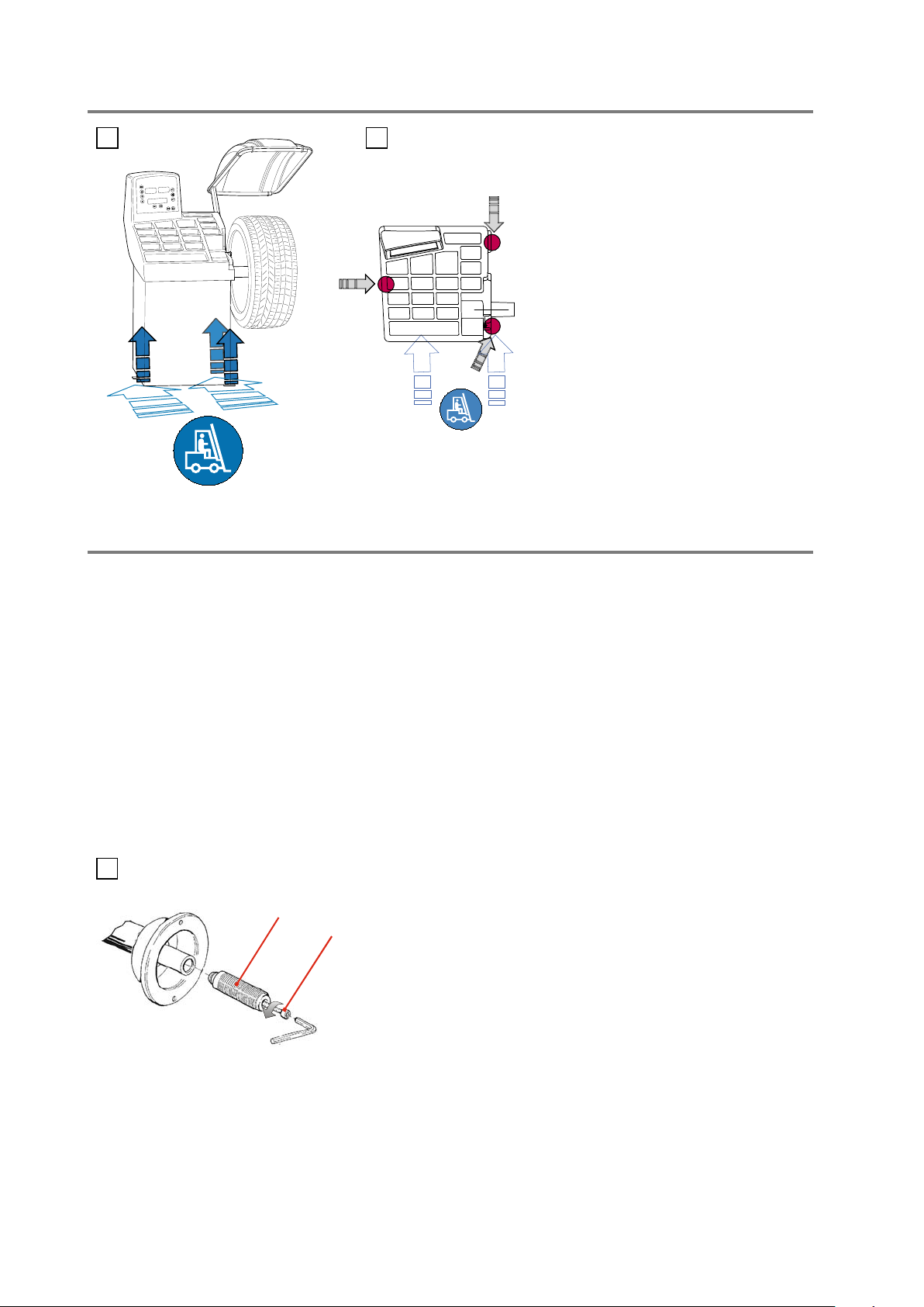
2 - Handling and lifting
2 2a
3 - Startup
NOTE: DO NOT LIFT THE WHEEL
BALANCER USING OTHER GRIPS.
3.1 - Anchoring
The machine can operate on any flat non resilient floor.
Make sure that the machine rests solely on the three support points provided (Fig.2a).
3.2 - Electrical connection
The machine is supplied with a single-phase mains cable plus earth (ground).
(any extension cables must have a cross-section of no less than 2.5 mm2).
The power supply voltage (and mains frequency) is indicated on the machine identification plate and cannot be
changed. Connection to the mains must always be made by expert personnel.
The machine must not be set up without proper earthing.
Connection to the mains should be through a slow acting safety switch rated at 16 A (230V) or 40A (115V). See enclosed
diagrams.
3.3 - Flange mounting
3
The wheel balancer is supplied complete with cone flanges
for fixing wheels with a central hole.
adaptors :
a) Remove the threaded end-piece A after unscrewing the screw B.
b) Mount the new flange (see attached sheets).
NOTE: CAREFULLY CLEAN THE COUPLING SURFACES BEFORE
PERFORMING ANY OPERATION.
To mount other optional flange
3.4 - Wheel guard assembly and adjustment (optional)
a) Fix the components to the base as described in the attachment “WHEEL GUARD ASSEMBLY SEQUENCE” at
the end of the manual.
Note: Do not lean on the guard during the wheel balancing cycle.
I 0539 - 4
GB
Page 5

Spring
DC
WD
Cone
3.5 - WD spacer
3a
To move the wheel away from the machine side (e.g. for
very wide wheels), fit the WD spacer on the flange body
and secure it with the standard issue nuts. When centring
the wheel with cone from the inside, mount the DC spacer
to obtain spring thrust.
These devices are optionals (see
flange details enclosed).
4 - Controls and components
4.1 - Automatic distance and diameter gauge
Allows automatic measurement of the distance from the machine and the wheel diameter at the counterweight
application point. The same gauge can be used to position the counterweights correctly inside the wheel, using the
specific function that suggests the position memorised during measurement inside the rim.
4.2 - Keyboard and display
4
6
1
7
8
9
3
15
5E5I
1-2 Digital readouts, AMOUNT OF
UNBALANCE, inside/outside
3-4 Digital readouts, POSITION OF
UNBALANCE, inside/outside
5I INSIDE correction position selection button
5E EXTERNAL SIDE and STATIC correction
position selection button
10 Push button, unbalance reading < 5 g
(.25 oz)
11 Push button, SPLIT (unbalance spread)
12 Position repeater push button
13 Push button, cycle start
14 Push button, emergency/home
15 Dot matrix function display
6 Push button, FUNCTIONS MENU
7 Push button, MENU selection confirmation
8 Maximize/MENU button
9 Minimize/MENU button
Note: - Press buttons only with your fingers. Do not use the counterweight grippers or other pointed
objects.
2
4
13 14
RED
GREEN
YELLOW
10
11
12
I 0539 - 5
GB
Page 6

I 0215 - 7
0I
MENU
STOP
4.2.1 - Function menu management
See chapter on unbalance optimisation
UP
UP
DOWN
DOWN
See chapter on AUTODIAGNOSTICS
See chapter on AUTOCALIBRATION
diameter
mm/inch
mm/inch
width
start from
guard closing
approx.1-5 g or
0.1-0.25 oz
on/off beep
signal
g/oz unit of
measure
unbalance
Screen-saver
duration
(in minutes)
CONFIRM
CONFIRM
CONFIRM
CONFIRM
CONFIRM
CONFIRM
CONFIRM
Calibration of automatic RIM DISTANCE gauge
Calibration of automatic DIAMETER gauge
RETURN TO MEASUREMENT FRAME
I 0539 - 6
GB
Page 7

b
5 - Instructions for use of the wheel balancer
5.1 - Using the gauge installed on the machine
5.1.1 - Data setting
For clamp weights, use the gauge in the top position A.
For adhesive weights, use the gauge as preferred in top position A or
bottom position B.
Note: Always use the round part of the striker plate resting on
the rim.
Indication of gauge in movement
5a
5
POS. A
POS. B
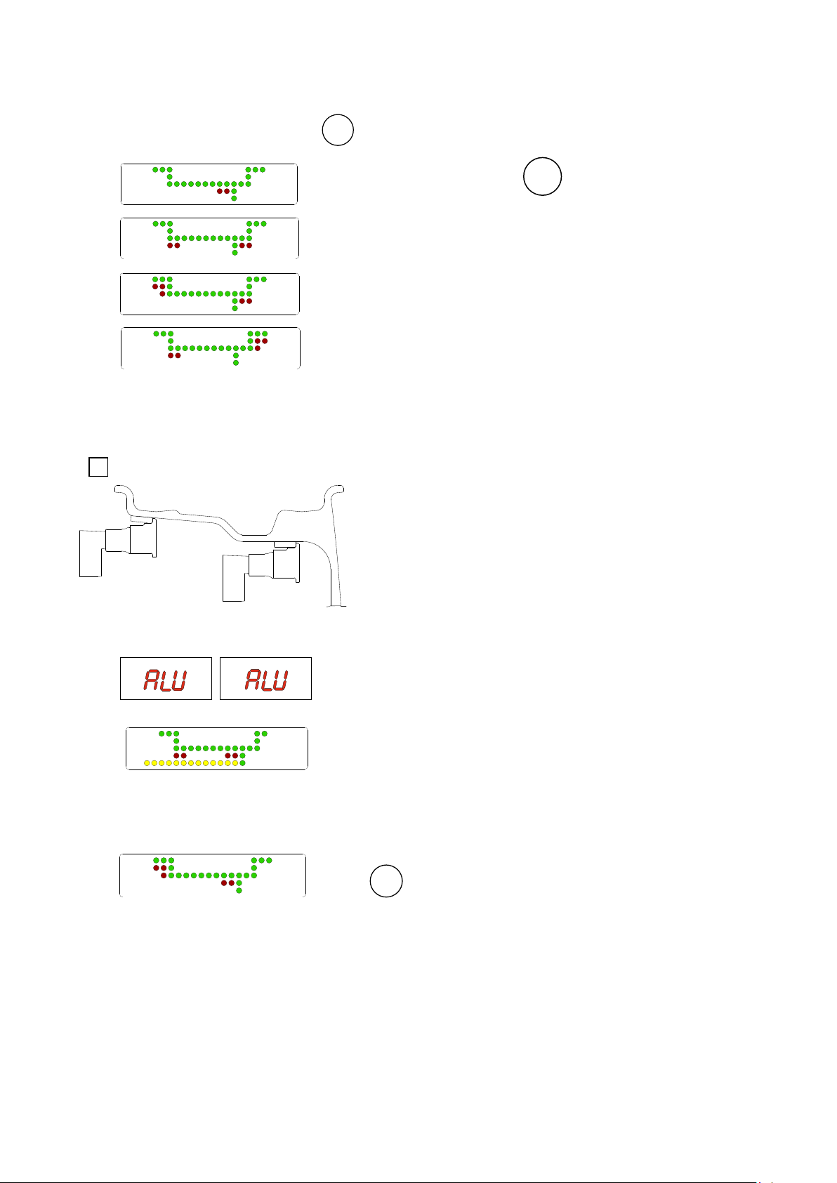
5.2 - Automatic presetting
The machine automatically detects the correct balancing program for steel and aluminium rims (ALUS).
ALU
The counterweight position proposed may be changed using the two
5.2.1 - Steel or aluminum wheel rims. Sprung counterweights
5b
buttons.
5c
Pull out the gauge as far as the inner edge of the rim.
position until a “beep” is heard.
Indication of dimensions acquired
Return the gauge to rest position. The machine has automatically
detected DISTANCE + DIAMETER and goes to MANUAL WIDTH
SETTING.
- The nominal width is normally stamped
on the rim; if not, proceed to measure
dimension “b” with the calibre gauge
(supplied as standard).
Hold it in this
5d
I 0539 - 7
GB
Page 8
5.2.1.1 - Static & combined modes
After calibration as per STEEL OR ALUMINUM WHEEL RIMS. SPRUNG COUNTERWEIGHTS, it is possible to modify the
position of the correction weights using the
5.2.2 - Rims with internal counterweight
6
ALU
buttons.
STATIC: Select by pressing
ALU
(5E)
Balancing of light alloy rims with application of adhesive weights
on the shoulders of the rims.
Combined balancing: adhesive weight on the outside and clip-on
weight on the inside.
Combined balancing: adhesive weight on the inside and clip-on
weight on the outside.
Slide out the gauge on the LH side, at the point where a weight is
to be fitted. Wait for the “beep”.
Slide it out further towards the RH
side and wait for a second “beep”. The wheel balancer
automatically identifies ALUS mode.
I 0539 - 8
GB
Counterweight position automatically suggested.
ALU
(5I) can be used to set the alternative position indicated.
Page 9

5.3 - Measurement result
After performing a balancing spin, the amounts of unbalance are shown on the digital readouts. The illuminated LEDs
3 and 4 indicate the correct angular position of the wheel to mount the counterweights (12 o’clock).
7a
Fig. 7A - Inside correction
7b
Fig. 7B -
If the unbalance is less than the threshold value selected,
the values below the threshold can be read.
5.3.1 - Measurement precision
The machine uses special devices (WP) to ensure the best possible measurement speed and controlled measurement
precision less than 1 gr. Operation is automatic and the measurement is highlighted as soon as sufficient precision is
reached. In the event of excessive vibration of the floor or exceptional shock, the wheel balancer might execute the
maximum number of permissible measurements. In this case, the following symbol is displayed:
Correct the result all the same and check with a test launch.
is displayed instead of the unbalance value; with
Outside correction
<T
5.4 - Recalculation of the unbalance
ALU
Automatic on varying set-up with the buttons
.
5.5 - Exact positioning of the adhesive weight by means of the gauge with clips
- press
- Fit the correction weight in the specific gauge seat with the adhesive
part facing upwards
- bring the wheel into correct angular position for the plane to be
corrected
- withdraw the gauge until the correction plane indication arrows turn
green
INSIDE CORRECTION POSITION
OUTSIDE CORRECTION POSITION
- rotate the gauge until the correction weight adheres to the rim
- the fact that the weight application position is no longer vertical (Fig. 8)
is automatically compensated
- to cancel this function, press button again
8
N.B. : It is not possible to put automatically the correction
weight in the Fig.5/B position; always rotate the rim in
Fig.5/A
upwards.
I 0539 - 9
GB
Page 10

15
30
15
30
15
30
MENU
START
START
STOP
5.6 - SPLIT function (hidden weight)
The SPLIT function is used to position the adhesive weights behind the wheel spokes so that they are not visible. Input
the wheel dimensions and do a spin.
- Place the wheel in the outside unbalance correction position.
- Set one of the top spokes to 12 o’clock.
- Press
Indication of first positioning detected
- Follow the UP/DOWN indication of the arrows and set the second top
spoke to 12 o’clock position.
- Press
- Place the first Split unbalance in correction position 1
- Correction position 1 (indicator 1)
1
- Correction position 2 (indicator 2)
2
N.B.: If errors 24/25/26 are displayed, see the table on page 17 and
repeat the split function with greater care.
To return to normal unbalance display, press any button.
To carry out a new spin, press the button
START
.
I 0539 - 10
GB
Page 11

MENU
START
START
STOP
5.7 - Unbalance optimisation
- This function serves to reduce the amount of weight to be added in order to balance the wheel
- It is suitable for static unbalance greater than 30 g.
- It improves the residual eccentricity of the tyre.
No previous
unbalance
measurement
Unbalance already measured
unbalance measurement
- With a piece of chalk make a reference mark on the flange and the rim
- With the aid of a tyre remover, turn the tyre on the rim by 180°
- Refit the wheel in such a way that the reference marks on the rim and
the flange coincide.
- RH display: percentage reduction value
- LH display: actual static unbalance value which can be reduced by
rotation
RIM IN POSITION INDICATION
- Mark the tyre (12 o’clock position)
TYRE IN POSITION INDICATION
- Mark the rim (12 o’clock position)
Turn the tyre on the rim until the marks correspond to obtain the
optimization shown on the display.
CANCEL OPTIMISATION IN ANY PHASE.
I 0539 - 11
GB
Page 12

5.8 - Automatic minimization of static unbalance
This program is designed to improve the quality of
balancing without any mental effort or loss of time by
the operator. In fact by using the normal commercially
available weights, with pitch of 5 in every 5 g, and by
applying the two counterweights which a conventional
wheel balancer rounds to the nearest value, there could
be a residual static unbalance of up to 4 g. The damage
of such approximation is emphasized by the fact that
static unbalance is cause of most of disturbances on
the vehicle. This new function, resident in the machine,
automatically indicates the optimum entity of the
weights to be applied by approximating them in an
“intelligent” way according to their position in order to
minimize residual static unbalance.
residual static
With conventional
wheel balancer
Initial unbalance
phase shift
Possible approximations
residual static residual static
residual static
Choice with minimum
static residual
6 - Set up
6.1 - Autodiagnostics
performs tests useful for maintenance staff
6.2 - Autocalibration
For autocalibration proceed as follows:
- Fit a wheel with steel rim of average dimensions on the shaft. Example 6” x 14” (± 1”)
- Set the exact dimensions of the wheel mounted.
CAUTION !! Setting incorrect dimensions will result in the machine not being properly calibrated and hence all the
subsequent measurements will be incorrect until a new autocalibration is performed with the correct
dimensions!! N.B.: Use steel wheel rims detection from “MANUAL DIMENSION PRESETTING”.
START
START
START
- Perform a spin under normal conditions.
- Add a 100 g. sample weight (3.5 oz) on the outside in any angular
position.
- Shift a 100 g sample weight from the outside to the inside keeping
the same angular position.
- Turn the wheel until the 100 g weight is in the 12 o’clock position.
END OF AUTOCALIBRATION
I 0539 - 12
GB
STOP
CANCEL AUTOCALIBRATION IN ANY PHASE.
Page 13
d
b
a
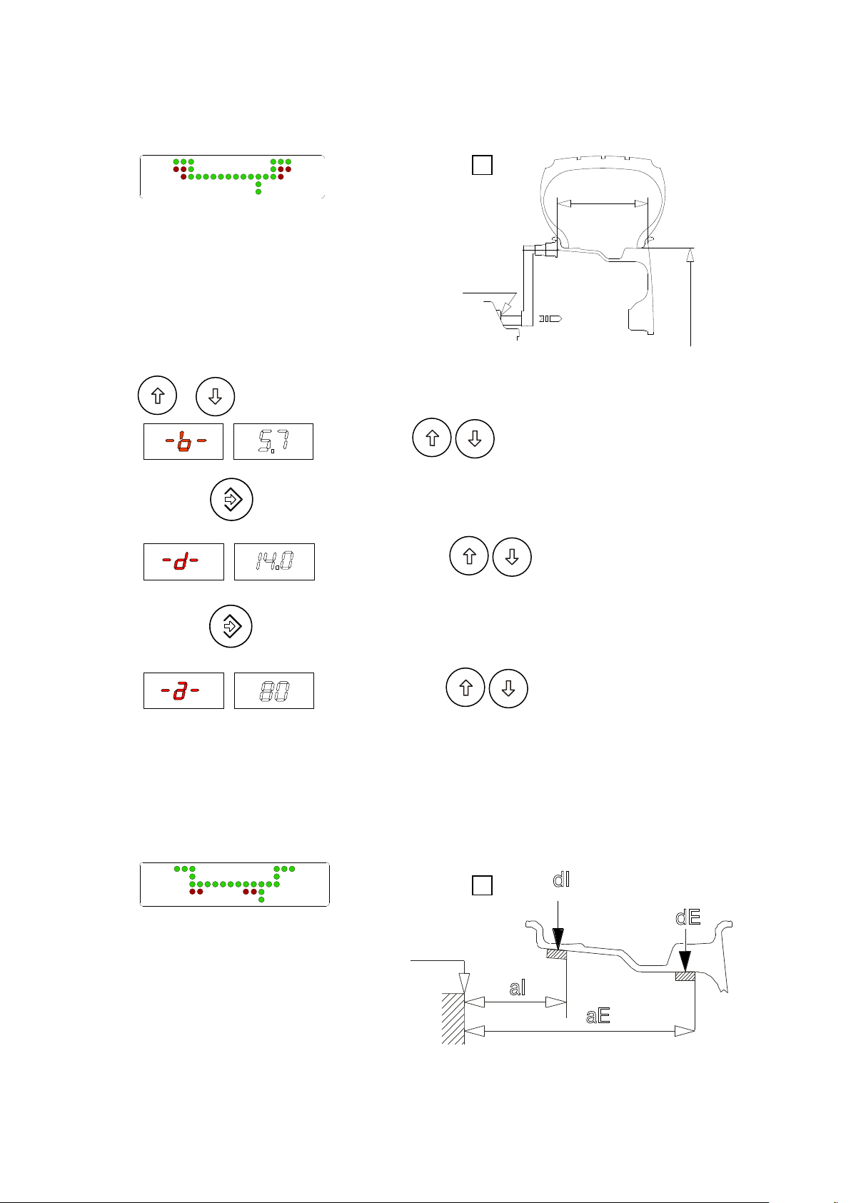
6.3 - Manual dimension presetting (Use only in particular cases or for test)
6.3.1 - Steel wheel rims (use for setting dimensions in AUTOCALIBRATION)
9
- Setting:
Press or
Set with the rated width that, in general, is shown on
the rim, or measure width “b” with the calliper gauge supplied.
6.3.2 - ALUS rims
- Press the button for more than 2 seconds
- Preset using the nominal diameter “d” indicated on the
tyre
- Press the button for more than 2 seconds
- Preset using distance “a” for the inside of the wheel
from the machine.
N.B.: This setting is also valid for the correction modes
indicated at “STATIC & COMBINED MODES”
10
0 gauge
I 0539 - 13
GB
Page 14

- Setting:
6.3.2.1 - ALUS variant with inside clamp weight
To go to these functions:
- press one of the two buttons for more than 2 seconds
- Hold the button down for more than 2 seconds
- Hold the button down for more than 2 seconds
- Hold the button down for more than 2 seconds
N.B.: when dE is not set, dE = dI - 1” is automatic.
- Setting:
11
0 gauge
To go to these functions:
- press one of the two buttons for more than 2 seconds
- press one of the two buttons for more than 2 seconds
- press one of the two buttons for more than 2 seconds
I 0539 - 14
GB
- press one of the two buttons for more than 2 seconds
N.B.: when dE is not set, dE = dI - 2” is automatic.
Page 15

6.4 - Display saver
It is possible to enable a screen saver function which temporarily replaces the data displayed with moving symbols.
This function acts when the balancing system is not used for the time period defi ned in the relative set-up:
Modify time expressed in minutes.
CONFIRM
If the value is set to 0, the display saver is automatically
disenabled. The display saver is not active in the balancing
machine set-up menu.To return to normal balancing machine
function, simply press any button or move the wheel.
6.5 - Automatic gauges calibration
6.5.1 - Rim distance gauge
- Shift the distance gauge to position 0, keeping it quite still,
press
- Move the gauge to position 150, press
CORRECT CALIBRATION
- Return the gauge to rest position.
- The wheel balancer is ready for operation.
N.B.: In the event of errors or faulty operation, the writing "P.O.”
appears on the display : shift the gauge to position 0 and repeat
the calibration operation exactly as described above. If the
error persists, contact the Technical Service Department. In the
event of incorrect input in the rim distance gauge calibration
function, press
STOP
to cancel it.
I 0539 - 15
GB
Page 16
40 mm
40 mm
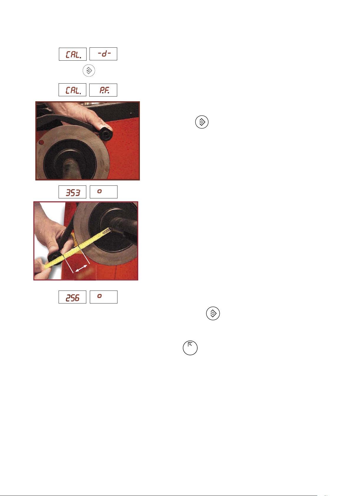
6.5.2 - Diameter gaugeE40 mm
Place the round part of the gauge terminal on the fl ange as shown in
the fi gure and press
.
- The number 353 ± 1° appears on the left display .
- Turn the gauge downward position the round part of the gauge
terminal at 40 mm (radial distance) from the fl ange as indicated
in the fi gure.
- The number 256 ± 3° should appear on the left display.
- If not, press the button
holding the gauge still at 40 mm: the
number 256 appears on the left display.
- Return the gauge to rest position.
In the event of incorrectly accessing the diameter gauge calibration
function, press
STOP
to cancel it.
I 0539 - 16
GB
Page 17

7 - Errors
During machine operation there may be various causes of malfunctioning which, if detected by the microprocessor,
are indicated on the display:
ERRORS CAUSES CONTROLS
Black The wheel balancer does not come on. 1. Check proper connection to the mains.
Err. 1
Err. 2 Too low speed during measurement.
Err. 3 Too high unbalance. 1. Check the wheel dimension setting.
Err. 4
Err. 5
Err. 7 /
Err. 8 /
Err. 9
Err. 11 Too high speed error.
Err.14/
Err.15/
Err.16/
Err.17/
Err. 18/
Err. 19
Err. 20 Wheel at standstill. The wheel is at a
Err.21
Err.22
No rotation signal. 1. Check belt tautness.
During the unbalance measurement
revolutions, the wheel speed has fallen to
below 42 rpm.
Rotation in opposite direction.
After pressing [START], the wheel
starts turning in the opposite direction
(anticlockwise).
Guard open
The [START] pushbutton was pressed
without first closing the guard.
NOVRAM parameter read error 1. Repeat machine calibration
The average spinning speed is greater than
240 rpm.
Unbalance measurement error. 1. Check functioning of the phase generator.
standstill for more than one second after
START.
Motor on for more than 15 seconds. 1. Check functioning of the phase generator.
Maximum number of spins possible for
the unbalance measurement has been
exceeded.
2. Check and if necessary replace the fuses on the power board.
3. Replace the computer board.
2. Check functioning of the phase generator and, in particular, the
reset signal.
3. Replace the phase generator.
4. Replace the computer board.
1. Check that a vehicle wheel has been mounted on the wheel
balancer.
2. Check belt tautness.
3. Check functioning of the phase generator and, in particular, the
reset signal.
4. Replace the computer board.
2. Check the sensor connections.
3. Run the machine calibration function.
4. Mount a wheel with a more or less known unbalance (less than 100
grams) and check the machine response.
5. Replace the computer board.
1. Verify the connection of the UP/DOWN - RESET signals on the
phase generator.
1. Reset the error.
2. Close the guard.
3. Verify the function of the protection Switch.
4. Press the [START] button.
2. Shut down the machine.
3. Wait for at least ~ 1 min.
4. Restart the machine and check proper functioning.
5. Replace the computer board.
1. Check if there is any damage or dirt on the timing disc.
2. Check functioning of the phase generator and, in particular, the
reset signal.
3. Replace the computer board.
2. Check the sensor connections.
3. Check the machine earthing connection.
4. Mount a wheel with a more or less known unbalance (less than 100
grams) and check the machine response.
5. Replace the computer board.
1. Check functioning of the phase generator.
2. Check the connections on the power board.
3. Replace the computer board.
2. Check the connections on the power board.
3. Replace the computer board.
1. Check that a vehicle wheel has been mounted on the wheel
balancer.
2. Check belt tautness.
3. Check functioning of the phase generator and, in particular, the
reset signal.
4. Replace the computer board.
I 0539 - 17
GB
Page 18

Err. 24 Distance between the spokes smaller
Err. 25
Err. 26 Distance between the first selected spoke
Err.32/
Err.33/
Err.34/
Err.35/
Err.36/
Err.37
than 18 degrees.
Distance between the spokes greater
than 120 degree
and unbalance greater than 120°.
Errors related to test functions of the wheel
balancer.
1. The minimum distance between the spokes where to split the
unbalance must be greater than 18 degrees
2. Repeat the SPLIT function increasing the distance between the
spokes.
1. The minimum distance between the spokes where to split the
unbalance must be smaller than 120 degrees
2. Repeat the SPLIT function increasing the distance between the
spokes.
1. To perform the SPLIT function correctly, the unbalance must be
inside two spokes no more than 120° apart.
2. Repeat the SPLIT function selecting a spoke nearer the unbalance.
1. Cancel the error and continue using the wheel balancer as normal.
7.1 - Inconsistent unbalance readings
It may occur that after balancing a wheel, when removing it from the wheel balancer and then remounting it, the
wheel is not balanced.
This is not the result of an incorrect indication by the machine, but only of incorrect mounting of the wheel on the
flange, i.e. in the two mountings the wheel has assumed a different position with respect to shaft axis of the wheel
balancer. If the wheel has been mounted on the flange with screws, it may be that the screws have not been tight
ened correctly in gradual criss-cross manner one after the other, or (as often occurs) holes have been drilled in the
wheel with too wide tolerances.
Small errors, up to 10 grams (0.4 oz), are to be considered normal in wheels locked with a cone: the error is normally
greater for wheels locked with screws or studs.
If, after balancing, the wheel is still unbalanced when refitted on the vehicle, this could be due to the unbalance of
the brake drum or very often is due to the screw holes in the rim and the drum drilled with too wide tolerances. In this
case a readjustment would be advisable using the wheel balancer with the wheel mounted.
-
8 - Routine maintenance
Before carrying out any operation on the machine, cut the power supply to the machine.
8.1 - Replacing the protection fuses
A protection fuse is fitted on the power board, accessible by dismantling the weight shelf (see Exploded Drawings). If fuses
require replacement, use ones with an identical current rating.
If the fault persists, contact Technical Service.
NONE OF THE OTHER MACHINE PARTS REQUIRE MAINTENANCE.
I 0539 - 18
GB
Page 19

9 - List of recommended spare parts (references on exploded drawings)
CODE DESCRIPTION
181198630 Spring 19863P
67M64690A Phase generator board
05PR59195 LEXAN Panel
182185750 Distance gauge spring
681002000 Fuse DM5x20 - 2A
511242101 Bipolar stub switch
86SC59755 Computer board
86SB59758
86SB59757 Cable, automatic diameter gauge
86SB59759 Cable with micro protection
568007058 Capacitor 70MF 450V Faston screw M8
50FG58735 Stator 230V/50 - 60 Hz
SPECIAL PARTS FOR 230V MACHINES
67M65573A Power board
SPECIAL PARTS FOR 115V MACHINES
67M65573B Power board
613010009 Auto-transformer
Cable, automatic rim distance gauge
I 0539 - 19
GB
 Loading...