


 Loading...
C A T E Y E PADRONE+
CYCLOCOMPUTER
CC-PA110W
Mounting the |
1 |
computer |
|
|
|
Setting up the |
2 |
computer |
Starting |
3 |
measurement |
|
•This instruction manual is subject to change without notice. See our website for the latest instruction manual (PDF).
•Please visit our website, where a detailed Quick Start manual containing videos can be downloaded.
http://www.cateye.com/products/detail/CC-PA110W/manual/
1
Changing settings
Warning / Caution Product Warranty, etc.
SET 4
Appendix

Mounting the computer
Bracket band |
Bracket rubber pad |
Speed sensor |
Magnet |
Bracket |
Dial |
Sensor rubber pad |
Nylon tie |
|
|
(x2)
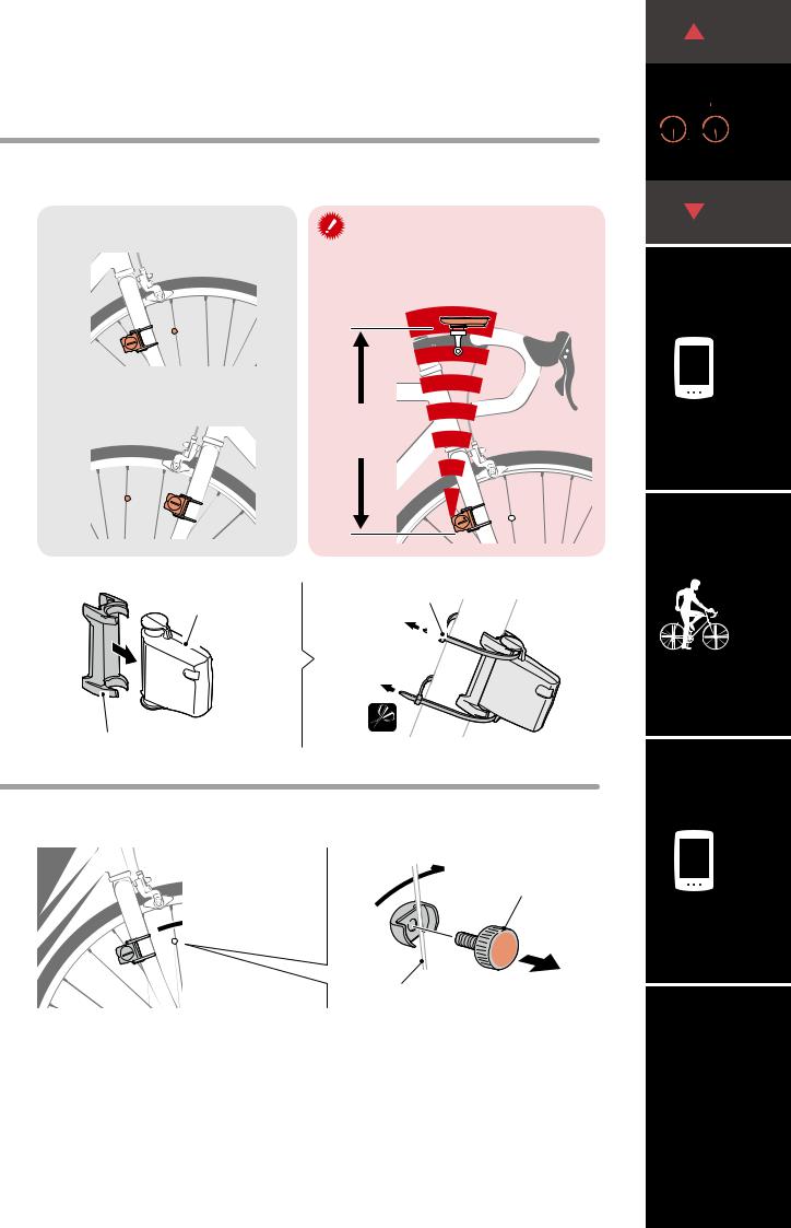
1 Mount the bracket
• When mounting on stem
Bracket band |
Bracket rubber pad |
Bracket
• When mounting on handlebar
Bracket band |
Bracket rubber pad |
Bracket |
|
When mounting the bracket on a handle- |
Correct |
bar, adjust the angle of the bracket so that |
|
the back of the computer faces the speed |
|
sensor when the computer is attached. |
|
Stem
Handlebar
Wrong
Cutting band after mounting |
Dial |
CAUTION: |
|
Cut the bracket band so |
|
that cut end will not cause |
|
injury. |
Cut |
|


 1
1
(1/3)
(2/3)
2
3 |
SET 4
Appendix
2
Mounting the computer
2 Mount the speed sensor
• Mounting on right front fork
Mount the speed sensor in a position where the distance from the computer to the speed sensor is within the signal range.
• Mounting on left front fork |
Max. |
|
|
||
|
70 cm |
|
(1/3)


 1
1
(2/3)
(3/3)
2
Speed sensor
SENSOR |
ZONE |
|
Sensor rubber pad
3 Mount the magnet
Nylon tie
Pull tight
SENSOR |
ZONE |
|
Cut
Magnet
|
|
|
|
|
|
|
To sensor zone |
||
|
|
|||
Spoke |
||||
3 |
SET 4
Appendix
3
Mounting the computer
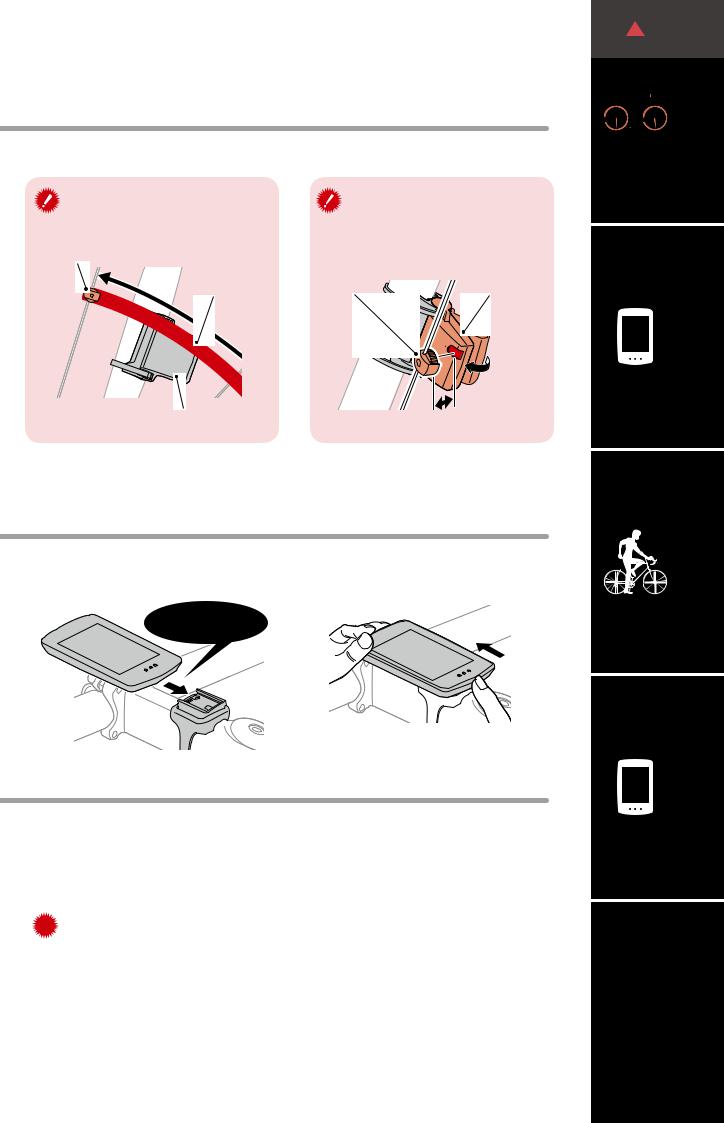
4 Adjust the speed sensor and the magnet
The magnet passes through the speed sensor zone.
Magnet
Sensor zone
SENSOR ZONE
Speed sensor
The clearance between the speed sensor and the magnet is within 5 mm (3/16”).
Magnet |
Speed sensor |
5 |
mm |
|
*The magnet may be mounted at any position on spoke as long as attachment conditions are satisfied.
5 Attach/detach computer
Hold computer.
 Click
Click
Push out so that front lifts up.
6 Test operation
After attaching the computer, rotate the front wheel gently to check that current speed is displayed on the computer.
If the speed is not displayed, refer to the attachment conditions in steps 1, 2, and 4  again.
(2/3)


 1
1
(3/3)
2
3 |
SET 4
Appendix
4
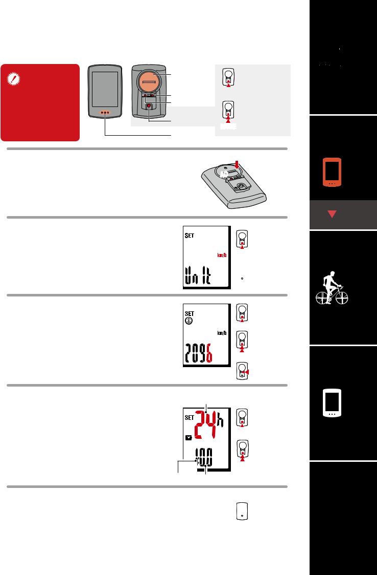
Setting up the computer
When using the computer for the first time, configure the initial settings.
Battery case |
Short press |
|
cover |
||
|
||
MENU |
MODE |
|
|
||
AC |
Long press |
|
|
||
MODE |
(2 sec.) |
|
MODE |
||
|
||
Dot section |
|
1
2
Clear all data.
Press the AC button on the back of the computer.
*All data is deleted and the computer is reset to its factory default settings.
Select the measurement unit.
Select “km/h” or “mph”.
 AC
AC 


km/h ↔ mph
MODE
 MENU Confirm
Set tire circumference. |
|
Increase |
|
3 Enter the tire circumference of the front wheel |
numbers |
||
MODE |
|||
in mm. |
|
Move to next digit |
|
* Refer to “Tire circumference”(page 6). |
|
(Press and hold) |
|
|
MODE |
||
|
|
||
|
|
MENU Confirm |
|
Set the clock. |
|
Time display mode |
|
4 Each time MODE is pressed and held, settings |
Switch between |
||
24h and 12h or |
|||
switch from time display mode, to hours, to |
|
MODE increase numbers |
|
minutes. |
|
Switch setting item |
|
* When 12h mode is selected, make sure to |
|
||
|
(Press and hold) |
||
check whether A (a.m.) or P (p.m.) is dis- |
|
MODE |
|
played before entering the value. |
|
||
Hours Minutes |
|||
|
|||
5 Press MENU to complete setup.
Setup is completed and the computer switches to the measurement screen. For instructions on how to start measurement, refer to “Starting measurement”(page 7).
 MENU
MENU
Setup complete


 1
1
2
(1/2)
(2/2)
3 |
SET 4
Appendix
5
Loading...