


CC-FR7CL
This device complies with Part 15 of the FCC Rules. Operation is subject to the following two
conditions: (1) This device may not cause harmful interference, and (2) this device must accept any
interference received, including interference that may cause undesired operation.
Modifications
The FCC requires the user to be notified that any changes or modifications made to this device that are
not expressly approved by Cat Eye Co., Ltd. may void the user’s authority to operate the equipment.
1
2
3
4
CAT EYE Cordless 7
CYCLOCOMPUTER CC-FR7CL
E OWNER’S MANUAL
®
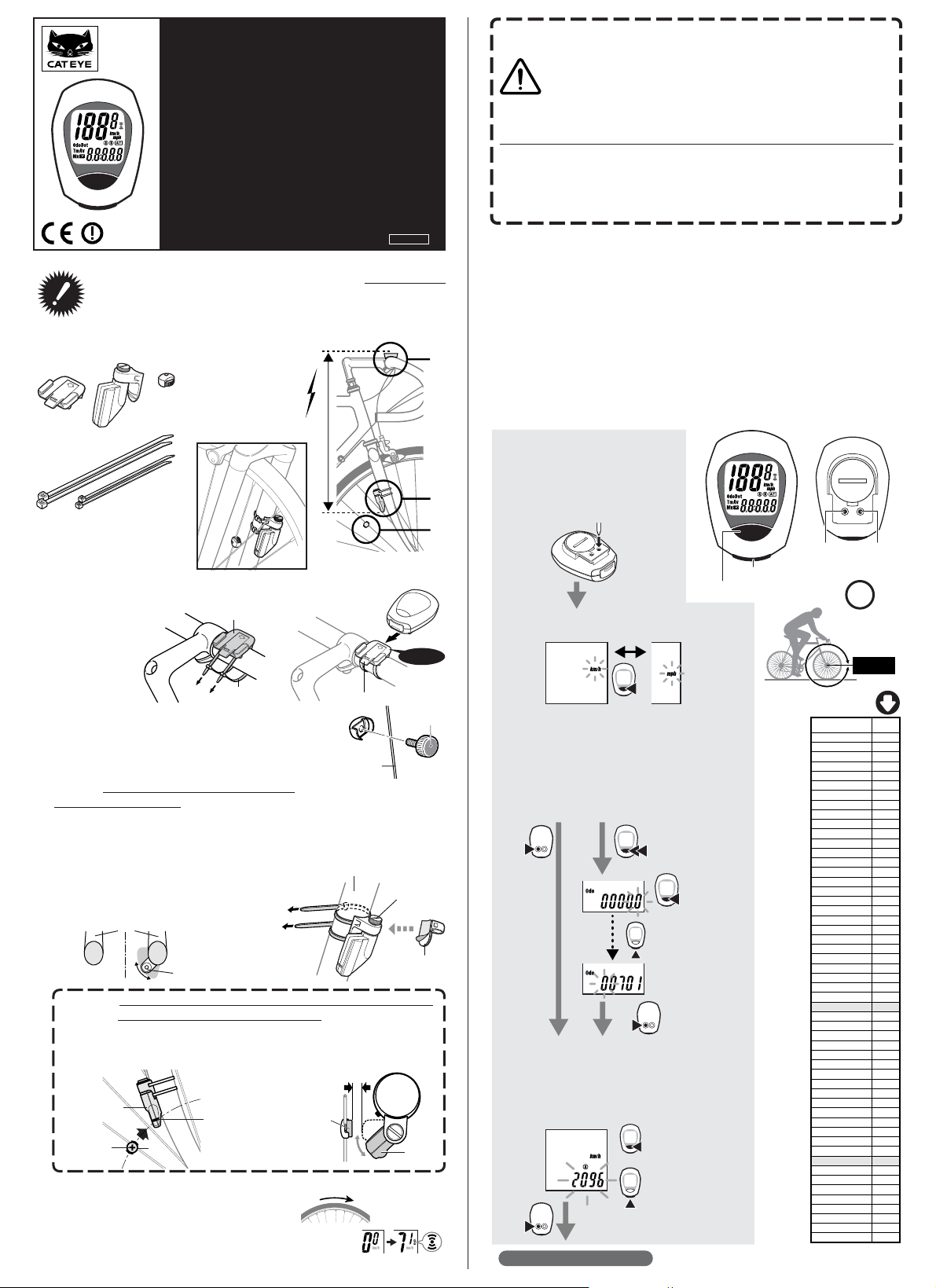
Installation of Computer:
Secure bracket to handlebar with nylon ties (fig. A).
Slide computer into mount until it snaps in place.
Mount the wheel magnet to a spoke on the front
wheel (fig.B), so the magnet faces the sensor.
Secure the sensor to fork leg as shown (fig. C).
NOTE: The
distance between the computer and the sen-
sor must not exceed 70 cm—if the sensor is too far
away from the computer head, the speed signal will not
register on the computer.
For best results, mount the sensor as high on the fork
leg as reasonably possible, so that the sensor is within
transmission range to the computer. However, the sen-
sor must be close enough to spokes to allow proper dis-
tance to magnet (see below).
Test by spinning the front wheel. Computer screen
should show speed. If not, make sure 1) the magnet is
close enough to sensor (within 5 mm); and 2) the sensor
is close enough to computer head (within 70 cm) and 3)
nothing is obstructing the line of sight between the sen-
sor and the computer head.
IMPORTANT! PLEASE READ INSTRUCTIONS COMPLETELY
BEFORE ATTEMPTING TO INSTALL AND USE YOUR CAT EYE
CORDLESS 7 COMPUTER.
Cordless 7
U.S. Pat. Nos.4633216/4636769/4642606/5236759 Pat. and Design Pat. Pending
Copyright© 2002 CATEYE Co., Ltd.
CCMFR7CL-021210 Printed in Japan 066600165
1
2
3
OK
2
3
1
2
3
4
5
Bracket
Sensor
(Transmitter)
Magnet
Nylon Ties (L x 2)
Nylon Ties (S x 2)
Sensor Pulse Indicator
Magnet's
center
Marking line
Less than 5mm
Spin
Max.
Distance
70 cm
1
3
2
NOTE: When the wheel rotates, the magnet MUST line up with the mark on the sensor.
ALSO NOTE:
Magnet must pass within 5 mm of the sensor—if not, it will not trip the
sensor as it passes, and the computer will not register speed. Adjusting the sensor
position higher or lower on the fork leg or by rotating the sensor on the fork mount may
be required to achieve proper distance to the wheel magnet.
3
!
Press the SET button to lock in your choice---OR---
if you want to input previous mileage, hold the
MODE button (before pressing the SET button) for
2 seconds.
• Flashing Odometer digits will appear.
• MODE button increases the digit number.
• START/STOP button moves to the next digit.
• Press the SET button when complete.
Press All-Clear button (AC).
Computer Set-up (for first use, or after replacing battery)
Get your wheel
circumference
move to the next digit
• Stored data is erased.
• Computer power is started.
• Total Odometer read's "zero".
• All digits shown then fades.
• Flashing "km/h" remains.
Adjust between “mph” or “km/h” by pressing
the MODE button.
•Wheel circumference number is shown.
• Look at chart to find TIRE SIZE in "mm".
• To increase TIRE SIZE press MODE button.
• To decrease press START/STOP button.
• 10-2999 mm can be registered.
• Press SET button when finished.
km/h mph
Setup Completed (To Tm)
Tire Size
L(mm)
12 x1.75 935
14 x 1.50 1020
14 x 1.75 1055
16 x 1.50 1185
16 x 1.75 1195
18 x 1.50 1340
18 x 1.75 1350
20 x 1.75 1515
20 x 1-3/8 1615
22 x 1-3/8 1770
22 x 1-1/2 1785
24 x 1 1753
24 x 3/4Tubular 1785
24 x 1-1/8 1795
24 x 1-1/4 1905
24 x 1.75 1890
24 x 2.00 1925
24 x 2.125 1965
26 x 7/8 1920
26 x 1(59) 1913
26 x 1(65) 1952
26 x 1.25 1953
26 x 1-1/8 1970
26 x 1-3/8 2068
26 x 1-1/2 2100
26 x 1.40 2005
26 x 1.50 2010
26 x 1.75 2023
26 x 1.95 2050
26 x 2.00 2055
26 x 2.10 2068
26 x 2.125 2070
26 x 2.35 2083
26 x 3.00 2170
27 x 1 2155
27 x 1-1/8 2161
27 x 1-1/4 2161
27 x 1-3/8 2169
650 x 35A 2090
650 x 38A 2125
650 x 38B 2105
700 x 18C 2070
700 x 19C 2080
700 x 20C 2086
700 x 23C 2096
700 x 25C 2105
700 x 28C 2136
700 x 30C 2170
700 x 32C 2155
700C Tubular 2130
700 x 35C 2168
700 x 38C 2180
700 x 40C 2200
1
2
3
increase
the figure
increase
the figure
AC Button
decrease
the figure
Use the below table
as the rough guide.
The tire size is marked on
both sides of the tire.
AC buttonSET button
ST./STOP button
MODE button
L mm
In this state Auto Time is ON.
ST./STOP
ST./STOP
MODE
MODE
MODE
SET
SET
SET
MODE
Precautions
•Do not concentrate too much on the computer operations while riding.
• Be sure to securely mount the magnet, sensor and bracket on your bicycle,
and alweys check to insure they are mounted securely.
• Used batteries must be disposed of properly and in accordance with all
local regulations.
•Never disassemble the computer.
• For cleaning, use mild soap and a soft cloth. Wipe dry with a soft cloth. Paint
thinner, benzine, alcohol or other chemicals may damage the surface.
About cordless system
The sensor picks up the wheel revolution signal and transmits the signal to the computer; the
computer calculates and displays the data on the screen.
CAUTION: In order to prevent external signal interference, the signal reception range is limited. For
best performance, the distance between the sensor and the computer must be kept within 70cm.
Attach the sensor at the upper part of your fork so that the distance becomes less than 70cm. The
signal reception range may shorten as a result of low temperature or lowered battery power.
In the following places and circumstances, interference may occur, resulting in malfunction:
• Near railroad crossing; in train cars.
•Near other cordless devices/television/personal computer/high power lighting system.
• Near the places where strong electromagnetic wave is generated; near television/ radio station; near
radar base.
•When being very close to another bicycle which also has a cordless cyclocomputer on its handlebar.
4
2
Sensor Screw
Sensor Base
Sensor Base
Front Fork
(fig. C)
(fig. B)
Spoke
5
1
Lever
Slide
Click
(fig. A)
Mounting View
Front Fork
 Loading...