

Page 1
CTK-691
INDEX
JUN. 2003
CTK-691
ELECTRONIC KEYBOARD
Ver.2 : Sep. 2006
Page 2

CONTENTS
Page
Specifications ............................................................................................................................................ 1
Block Diagram ........................................................................................................................................... 3
Circuit Description ..................................................................................................................................... 4
Printed Circuit Boards ............................................................................................................................... 5
Disassembly .............................................................................................................................................. 8
Diagnostic Program................................................................................................................................. 14
Schematic Diagrams ............................................................................................................................... 17
Exploded View ........................................................................................................................................ 22
Parts List ................................................................................................................................................. 23
Page 3
SPECIFICATIONS
GENERAL
Keyboard: 61 standard-size keys, 5 octaves with touch response (Off / 1 / 2 / 3)
Tones: 300 Advanced Tones + 200 Preset Tones + 16 Drum Sets + 100 standard
user tones + 20 user tones with waves*: + 4 drum sets with waves* + 50
drawbar organ tones + 100 user drawbar organ tones (790 tones total);
layer/split
Rhythm Instrument Tones: 61
Polyphony: 32 notes maximum (10 for certain tones)
Effects: DSP (200 types: internal, 100 user areas) + Reverb (16 types) + Chorus (16
types) + Equalizer (10 types, 4 bands)
Auto Accompaniment
Rhythm Patterns: 156 (internal, 16 user areas*)
Tempo: Variable (226 steps, = 30 to 255)
Chords: 3 fingering methods (CASIO CHORD, FINGERED, FULL RANGE CHORD)
Rhythm Controller: START/STOP, INTRO/ENDING 1 and 2, VARIATION/FILL-IN 1 and 2,
SYNCHRO/FILL-IN NEXT
Accomp Volume: 0 to 127 (128 steps)
One Touch Presets: Recalls settings for tone, tempo, layer on/off, and harmonize on/off in
accordance with rhythm.
Auto Harmonize: 10 types: Automatic addition of notes that harmonize with melody note in
accordance with specified Auto Accompaniment chords.
Memory Function
Songs: 5
Recording Tracks: 6 (2 through 6 are melody tracks)
Recording Methods: Real-time, step
Memory Capacity: Approximately 10,000 notes (total for 5 songs)
Edit Function: Equipped
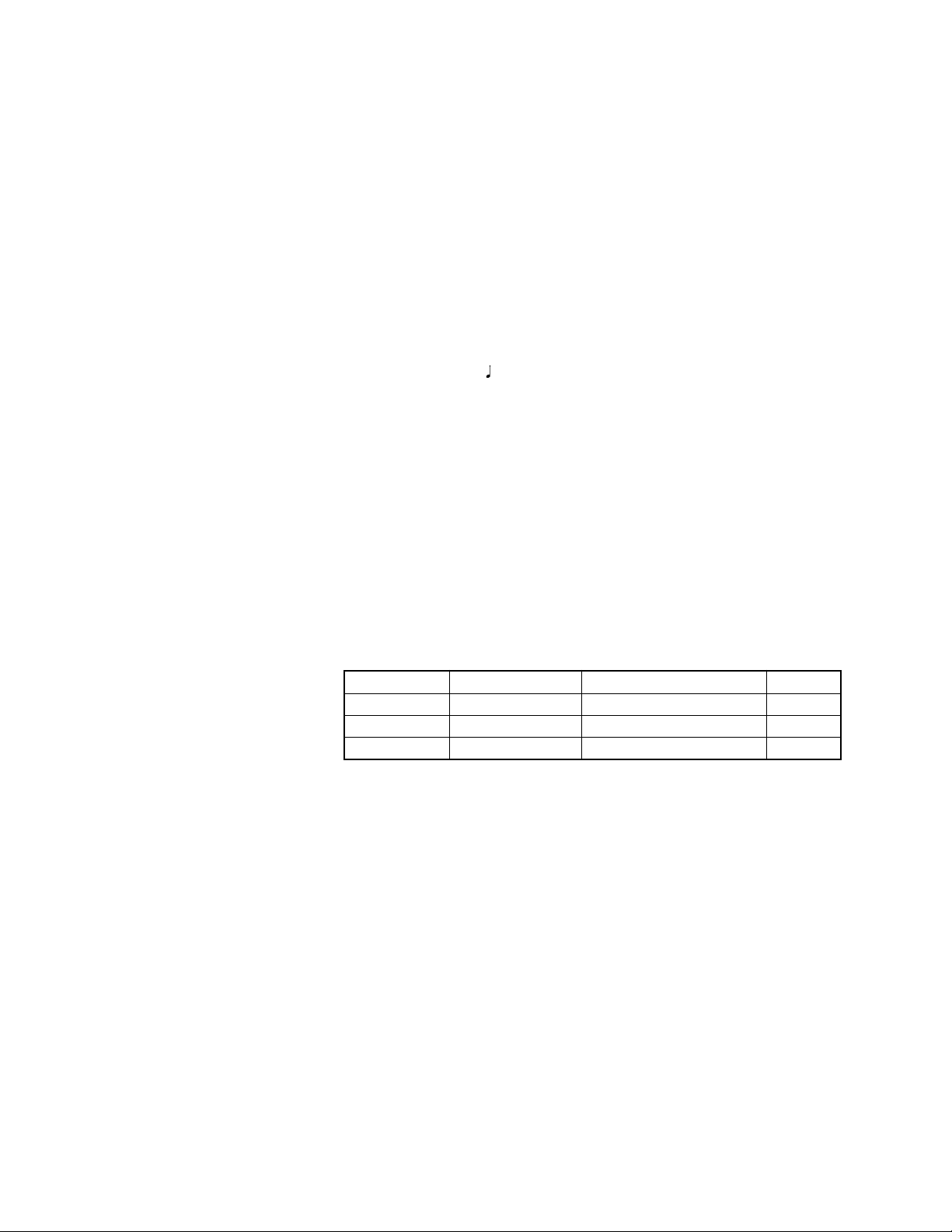
Demo Tunes: 3
Tune Number
0
1
2
Synthesizer Function
Parameters: Attack time; release time; resonance; cutoff frequency; vibrato type; vibrato
delay; vibrato depth; vibrato rate; octave shift; level; touch sense; reverb
send; chorus send; DSP line; DSP type and DSP parameter, DSP level.
Registration Memory
Number of Setups: 32 (4 setups × 8 banks)
Memory Contents: Tone, Rhythm, Tempo, Layer on/off, Split on/off, Split point, Harmonize on/
off, Mixer settings (Channels 1 to 10), Effect settings, Touch Response
settings, Assignable jack setting, Transpose, Tuning, Accompaniment
volume setting, Auto Harmonize type, MODE button setting, Synchro
standby state, Mixer Hold, DSP Hold, Synthesizer Mode parameters
Mixer Function
Channels: 16
Parameters: Tone; part on/off; volume; pan pot; octave shift; coarse tune; fine tune;
reverb send; chorus send; DSP line; DSP level; DSP pan; DSP system
reverb send; DSP system chorus send
MIDI: 16 multi-timbre receive, GM Level 1 standard
Name
Nora Park
Garage Flava
Strut With Beauty
Composer
TECH-NOTE INTERNATIONAL LTD.
Steave Turner
Edward Alstrom
Play time
2:06
2:15
1:52
— 1 —
Page 4

Other Functions
Transpose: 49 steps (–24 semitones to +24 semitones)
Tuning: Variable (A4 = approximately 440Hz ±100 cents)
LCD: Adjustable contrast
SMF Player Flash memory storage for up to 200 files*
• Supported Format: SMF0
Flash Memory Capacity: 2MB
Shared Area: Approximately 1.5MB (waveform data, accompaniment data,
SMF data)
• Further storage of waveform, accompaniment, and SMF data becomes
impossible after the total of such data reaches approximately 1.5MB.
Terminals
MIDI Terminals: IN, OUT
Sustain/Assignable Terminal:Standard jack (sustain, sostenuto, soft, rhythm start/stop)
Headphone/Output Terminal: Stereo standard jack
Output Impedance: 140Ω
Output Voltage: 4.5V (RMS) MAX
Power Supply Terminal: 9V DC
Power Supply: Dual power supply system
Batteries: 6 D-size batteries
Battery Life: Approximately 4 hours continuous operation on manganese batteries
AC Adaptor: AD-5
Auto Power Off: Turns power off approximately six minutes after last key operation. Enabled
under battery power only, can be disabled manually.
Speaker Output: 3W + 3W
Power consumption: 9V
Dimensions: 96.0 × 37.5 × 14.6 cm (37 13/16 × 14 3/4 × 5 3/4 inch)
Weight: Approximately 5.6 kg (12.3lbs) (without batteries)
7.7W
* The same memory area is used to store waveform data, accompaniment data, and SMF data.
ELECTRICAL
Current drain with 9 V DC:
No sound output 1200 mA ± 20 %
Maximum volume 260 mA ± 20 %
with 16 keys from C1 to D#2 pressed in 193 BREATHY ALTO SAX (R channel)
Volume: maximum, Velocity: maximum
Speaker output level (Vrms with 4 Ω load each channel):
with key G1 in 193 BREATHY ALTO SAX (R channel)
Volume: maximun, Velocity: maximum L/R: 3700 mV ± 20 %
Phone output level (Vrms with 32 Ω load each channel):
with key, E1 in 193 BREATHY ALTO SAX (R channel)
Volume: maximun, Velocity: maximum L/R: 320 mV ± 20 %
Output level (Vrms with 47 Ω load each channel):
with key E1 in 193 BREATHY ALTO SAX (R channel)
Volume: maximun, Velocity: maximum L/R: 1750 mV ± 20 %
About General MIDI
General MIDI standardizes MIDI data for all sound source types, regardless of manufacturer. General MIDI
specifies such factors as tone numbering, drum sounds, and available MIDI channels for all sound sources.
This standard makes it possible for all MIDI equipment to reproduce the same nuances when playing
General MIDI data, regardless of the manufacturer of the sound source.
This keyboard supports General MIDI, so it can be used to play commercially available pre-recorded
General MIDI data and General MIDI data send to it from a personal computer.
— 2 —
Page 5
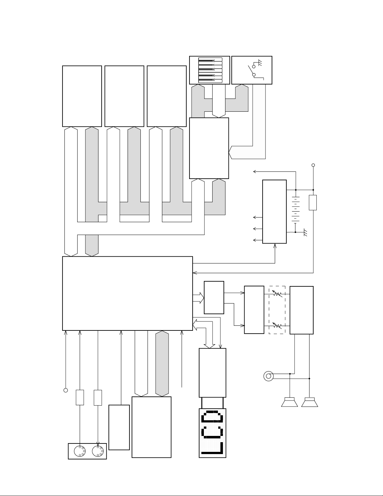
BLOCK DIAGRAM
MIDI
RAM (1Mbit)
IC2
CY62128VLL-70AZI
PEDAL
Assingnable Jack
Reset IC
IC4
R1151N001C-TR
RESET
16.384MHz
EA0 ~ EA19
ED12 ~ ED19
MA0 ~ MA20
MD0 ~ MD15
Q207
D209
Filter
IC202, IC203
DAC IC3
µPD6379LGR-E1
Main
Volume
Power Amplifier
IC201
LA4636
Power Supply Circuit
Q201 ~ Q206, D201,
D204, D205, D207, D208
(9V)
VC
(5V)
VD5
(5V)
VA5
(9V)
VCP
APO
ADIN
Battery
APO Cancellation
Speakers
(L)
(R)
Phones/Output
LOUT
CONT
ROUT
AC Adaptor
DC 9V
Keyboard
Buttons
FLASH ROM (16MBit)
IC5
LH28F160BJHE-BTL90
RAM (1Mbit)
IC12
CY62128VLL-70AZI
ROM (64Mbit)
IC8
MR27V6402G01BTNZ04
MA0 ~ MA21
MD0 ~ MD15
MD0 ~ MD15
MA0 ~ MA15, MA25
MA0 ~ MA23, MA25
MD0 ~ MD7
MA1 ~ MA3
MD0 ~ MD15
CPU
IC10
uPD914AGM-3ED
KEY/BOTTON
CONTROLLER
IC13
TC190C020AF-001
KC0 ~ KC7
SI0 ~ SI7
FI0 ~ FI7
FI8 ~ FI10, FI0 ~ FI7, KI0 ~ KI2,
LD14 ~ LD16, LD20 ~ LD22
LCD Controller
ML9040-B02GA (IC501)
IN
OUT
D203
MA0 ~ MA20
— 3 —
Page 6
KEY MATRIX
KC0 KC1 KC2 KC3 KC4 KC5 KC6 KC7-
CIRCUIT DESCRIPTION
FI0
SI0
FI1
SI1
FI2
SI2
FI3
SI3
FI4
SI4
FI5
SI5
FI6
SI6
FI7
SI7
C2 (1) C#2(1) D2 (1) D#2 (1) E2 (1) F2 (1) F#2 (1) G2 (1)
C2 (2) C#2 (2) D2 (2) D#2 (2) E2 (2) F2 (2) F#2 (2) G2 (2)
G#2 (1) A2 (1) A#2 (1) B2 (1) C3 (1) C#3 (1) D3 (1) D#3 (1)
G#2 (2) A2 (2) A#2 (2) B2 (2) C3 (2) C#3 (2) D3 (2) D#3 (2)
E3 (1) F3 (1) F#3 (1) G3 (1) G#3 (1) A3 (1) A#3 (1) B3 (1)
E3 (2) F3 (2) F#3 (2) G3 (2) G#3 (2) A3 (2) A#3 (2) B3 (2)
C4 (1) C#4 (1) D4 (1) D#4 (1) E4 (1) F4 (1) F#4 (1) G4 (1)
C4 (2) C#4 (2) D4 (2) D#4 (2) E4 (2) F4 (2) F#4 (2) G4 (2)
G#4 (1) A4 (1) A#4 (1) B4 (1) C5 (1) C#5 (1) D5 (1) D#5 (1)
G#4 (2) A4 (2) A#4 (2) B4 (2) C5 (2) C#5 (2) D5 (2) D#5 (2)
E5 (1) F5 (1) F#5 (1) G5 (1) G#5 (1) A5 (1) A#5 (1) B5 (1)
E5 (2) F5 (2) F#5 (2) G5 (2) G#5 (2) A5 (2) A#5 (2) B5 (2)
C6 (1) C#6 (1) D6 (1) D#6 (1) E6 (1) F6 (1) F#6 (1) G6 (1)
C6 (2) C#6 (2) D6 (2) D#6 (2) E6 (2) F6 (2) F#6 (2) G6 (2)
G#6 (1) A6 (1) A#6 (1) B6 (1) C7 (1)
G#6 (2) A6 (2) A#6 (2) B6 (2) C7 (2)
BUTTON MATRIX
KI0
KI1
KI2
FI8
FI9
FI10
KC0
LAYER
DEMO
KC1
9
6
3
+
8
0
1
2
—
5
KC2
DSP ON/OFF
PIANO SETTING
RHYTHM
CURSOR⇐
CURSOR⇑
TONE
CURSOR⇓
CURSOR⇒
DRAWBAR
KC3
EXIT
7
4
KC4
PART EDIT
TONE EDIT
SETTING
TEMPO UP
BANK
EFFECT EDIT
KC5
SEQ
ACCOMP VOLUME
ONE TOUCH PRESET
REGISTRATION 1
TEMPO DOWN
SMF PLAY
INTRO/ENDING 2
INTRO/ENDING 1
AUTO HARMONIZE
START/STOP
KC6
STORE
SPLIT
KC7
SYNCRO/FILL-IN NEXT
VARIATION/FILL-IN 2
VARIATION/FILL-IN 1
REGISTRATION 4
REGISTRATION 3
REGISTRATION 2
— 4 —
Page 7
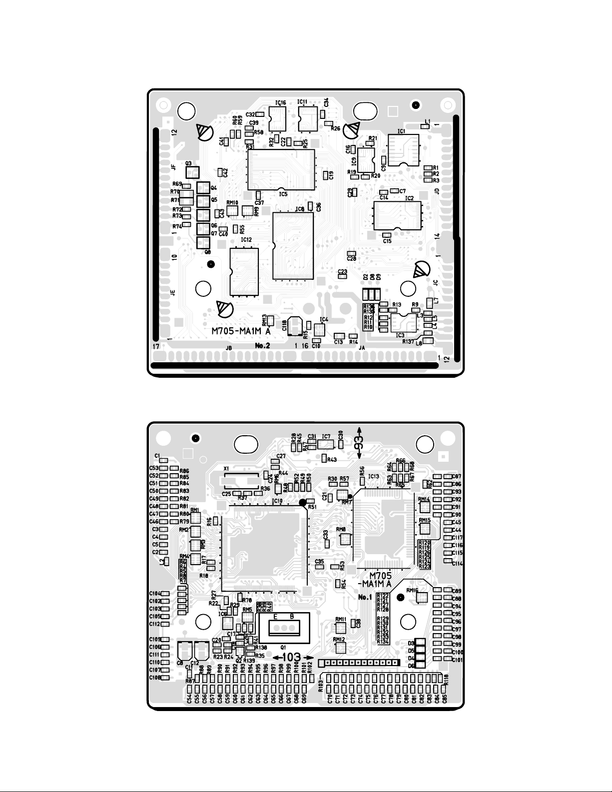
Main PCB M705-MA1M
PRINTED CIRCUIT BOARDS
Top View
Bottom View
— 5 —
Page 8
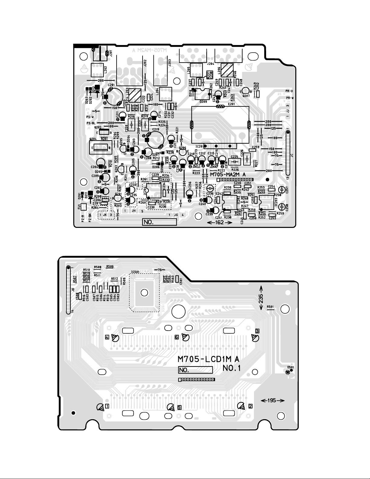
Sub PCB M705-MA2M
LCD PCB M705-LCD1M
Top View
Top View
— 6 —
Page 9
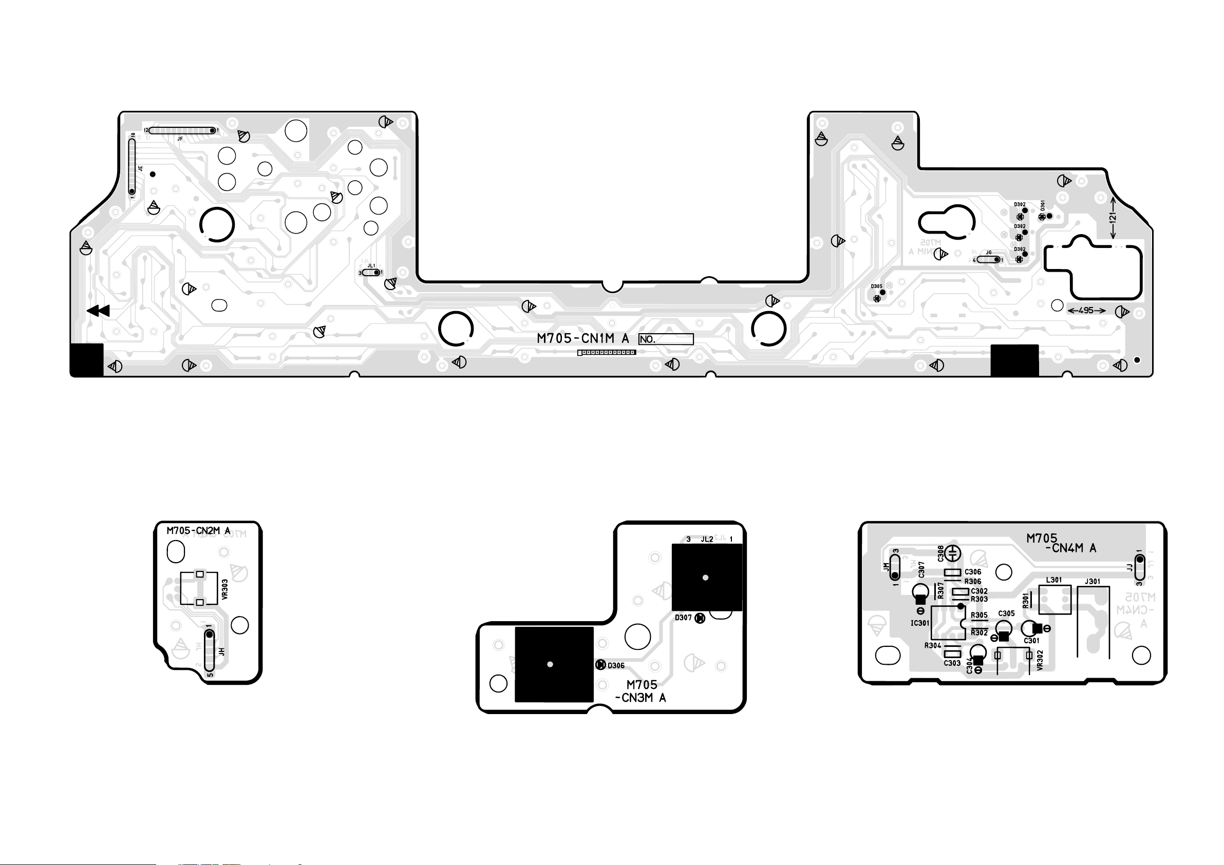
CONSOLE PCB M705-CN1M
CONSOLE PCB M705-CN2M
Top View
CONSOLE PCB M705-CN4MCONSOLE PCB M705-CN3M
Top View
Top View
Top View
— 7 —
Page 10

DISASSEMBLY
1. Remove the battery cover and then the battery.
2. Remove 27 screws and then the upper case.
3. Remove 5 screws, 4 speaker cords, 2 battery cords, 3 connectors (JC, JG, JH) and then the PCB ASS'Y
(MA2M).
Speaker cord (O)
Speaker cord (W)
Connectors
Screws
Speaker cord (W)
Speaker cord (BL)
Battery cord (R)
Battery cord (B)
— 8 —
Page 11

4. Remove 4 screws, 6 connectors (JA, JB, JC, JD, JE, JF) and then the PCB ASS'Y (MA1M).
Connectors
Screws
Connectors
Note: How to attach a HEAT-SINK
Insert aTRANSISTOR into the PWB after attaching a HEATSINK to the TRANSISTOR.
Be soldering sfter that.
HEAT-SINK
Connectors
TRANSISTOR
5. Remove 6 screws and then the LCD ASS'Y (LCD1M).
Screws
Screws
4
1
6
3
5
2
Note: Tighten the screws in the order from 1 to 6 when reassembling.
— 9 —
Page 12

6. Remove 3 screws, connector (JL), and then the PCB ASS'Y (CN3M).
Screws
Connector
7. Remove 2 screws, the volume knob, and then the PCB ASS'Y (CN2M).
Volume knob
8. Remove 22 screws and then the PCB ASSY (CN1M).
Screws
— 10 —
Page 13

Note: Fix the LED (D301, D302, D303, D304, D305, D306, D307) to the PCB according to the height as shown in
the figure below while paying attention to the polarity.
Refer to the illustration on the PCB for the details of the polarity.
D301
D302
D304
D303
D305
Note: Mount LED on the PCB. (solder side)
Correct polarity and height as follows.
■ D301, D302
15.0 ± 0.5 mm
Cathode
Anode
SOLDER SIDE
COMPONENT SIDE
D306
■ D303, D304
14.5 ± 0.5 mm
D307
SOLDER SIDE
COMPONENT SIDE
■ D305 ■ D306, D307
6.8 ± 0.5 mm
12.5 ± 0.5 mm
SOLDER SIDE
COMPONENT SIDE
9. Remove 13 screws and then the lower case.
Note: Tighten the screw with the arrow mark in the figure first when reassembling.
SOLDER SIDE
COMPONENT SIDE
Cushion
— 11 —
Page 14

10.Remove 19 screws and then the PCB ASSY (KY1M, KY2M).
11.Remove the rubber keys.
Projection
Note: Pay attention to the positions of the rubber keys as one of them has a different length.
Match the projections of the rubber keys with the holes of the lower case when reassembling.
— 12 —
Page 15

12.Remove 21 screws and then the white keys.
Note: Pay attention to the positions of the screw holes when
reassembling.
13.Remove the black keys.
— 13 —
Page 16

DIAGNOSTIC PROGRAM
7890ABCD
■Initial Setup
1. Connect an AC adaptor.
2. Connect a Sustain pedal.
3. "Main" volume: MAX.
NOTE: If there is no pedal or MIDI cable, pedal or MIDI check can be skipped.
■ How to start diagnostic program
1. Press the “POWER” button while pressing the “Cursor key Up” and “Cursor key Down” buttons.
2. Release the “POWER” button first while still pressing the “Cursor key UP” and “Cursor key Down”
buttons. After “000 Sy.Gr Pno” appears, release the “Cursor key UP” and “Cursor key Down”
buttons. “TEST 705” appears on the LCD.
NOTE: Refer to the figure below for the LCD messages that appear during the diagnostic program.
12 3 456
■ Diagnostic program
1. Button check
1 Press “DSP” button. Display indicates 3 “MODE”.
2 Press buttons in the following order.
NOTE:
NG sound sounds when a button is defective or buttons are pressed in a wrong order.
LCD message appears in the area 3
Message on LCD Message on LCD Message on LCD Message on LCD
1MODE
ONE TOUCH PRESET
2
3ACCOMP VOLUME
4INTRO/ENDING 1
5INTRO/ENDING 2
VARIATION/FILL-IN 1
6
7
VARIATION/FILL-IN 2
8
SYNCHRO/FILL-IN NEXT
9START/STOP
@TEMPO쑼
ATEMPO쑿
BBANK
OTP
ACMP VOL
INT/END1
INT/END2
VAR/FIL 1
VAR/FIL 2
SYNCHRO
STRT/STP
TEMPO/DW
TEMPO/UP
BANK
REGIST 1
CREGISTRATION 1
DREGISTRATION 2
EREGISTRATION 3
FREGISTRATION 4
GSTORE
TRANSPOSE/FUNCTION
H
IMIXER
JSYNTH
KEFFECT
LSONG MEMORY
MSMF PLAYER
NTONE
H
I
J
K
L
M
REGIST 2
REGIST 3
REGIST 4
STORE
TRN/FUNC
MIXER
SYNTH
EFFECT
SONG
SMF
TONE
RHYTHM
123
987654
A0
ORHYTHM
DRAWBAR ORGAN
P
QDSP
RPIANO SETTING
SCursor key Up
TCursor key Right
UCursor key Down
VCursor key Left
WEXIT
AUTO HARMONIZE
X
YSPLIT
ZLAYER
GFEDCB
DRAWBAR
DSP
PIANO
UP
RIGHT
DOWN
LEFT
EXIT
HARMO
SPLIT
LAYER
0
N
O
P
[0 buttons
\1 buttons
]4 buttons
`7 buttons
a8 buttons
b5 buttons
c2 buttons
d- buttons
e+ buttons
f3 buttons
g6 buttons
h9 buttons
iDEMO
V
W
Q
S
U
ZYX
R
i
^T
]
\
[
1
4
7
8
5
2
+
3
6
9
DEMO
SW OK
a
b
c
d
h
g
f
e
— 14 —
Page 17

2. AC adaptor detection check.
1 Press “TONE” button.
2
When the instrument detects that an AC adaptor is plugged in, an OK sound
sounds.
“ACJ OFF” appears and an NG sound sounds when the AC adaptor
is not plugged (when batteries are used).
3. Sustain jack check. (If no pedal, this check can be skipped)
1 Press “RHYTHM” button.
2 Press “Sustain pedal” .
3 Release “Sustain pedal” .
4 NG sound, “OFF” sound this case, must be audible.
4. Low Voltage detection check.
1 Press “DRAWBAR ORGAN” button.
2 OK sound must be audible.
5. MIDI IN/OUT check (If there is no MIDI cable, this check can be skipped)
1 Connect MIDI IN and MIDI OUT terminals with a MIDI cable.
2 Press “3” button.
3 Disconnect the MIDI cable.
6. ROM check
1 Press “INTRO/ENDING1” button.
2 OK sound must be audible.
Message on LCD
3 ACJ ON
3 SUS CHK
3 SUS ON
3 US OFF
3 VOLT HI
3 MIDI OK
4 ROM CHK
앗
3 ROM OK
7. Flash memory bus check
1 Press “INTRO/ENDING2” button.
2 OK sound must be audible.
8. DSP RAM check
1 Press “VARIATION/FILL-IN 2” button
9. CPU RAM check
1 Press “SYNCHRO/FILL-IN NEXT” button.
10. LED check
1 Press “TEMPO쑼” button.
2 LEDs illuminate in the following order.
a . FULL RANGE
b . FINGERED
c . CASIO CHORD
d . DATA ACCESS
e . DRAWBAR ORGAN
f . DSP
11. LCD check
1 Press “TEMPO쑿” button.
2 Turn on all segments of the LCD.
3 Press “BANK” button.
4 The area 3 turns as check pattern.
5 Press “REGISTRATION 1” button.
6 The area 3 turns as check pattern.
7 Press “REGISTRATION 2” button.
8 Half of characters in area 1 to D turn on.
9 Press “REGISTRATION 3” button.
3 FMB CHK
앗
3 FMB OK
3 DRAM OK
3 CRAM OK
3 LED CHK
앗
앗
앗
앗
앗
앗
앗
3 LED END
Except area 3
Except area 3
— 15 —
Page 18

= Rest of above characters turn on.
A Press “REGISTRATION 4” button.
B Each characters turn in order.
There no lack of dots and characters
12. TUNE check (If no TUNING METER, this check can be skipped)
1 Connect the TUNING METER to the phone jack.
2 Press “8” button.
3 The TUNING METER must indicate "C".
4 Disconnect the TUNING METER from the phone jack.
13. APO check
1 Press “EXIT” button.
* Go out from TEST mode (Power off).
* The keybord turns off after about 2 seconds.
* The LCD turns off.
DIAGNOSTIC PROGRAM IS FINISHED.
— 16 —
Page 19

Main PCB M705-MA1M
SCHEMATIC DIAGRAMS
— 17 —
Page 20

Sub PCB M705-MA2M
— 18 —
Page 21

CONSOLE PCBs M705-CN1M/CN2M/CN3M/CN4M
— 19 —
Page 22

Display PCB M705-LCD1M
— 20 —
Page 23

Keyboard PCBs JCM618T-KY1M/KY2M
— 21 —
Page 24

EXPLODED VIEW
37
38
18
25
36
17
32
26
21
23
22
28
24
27
38
3029
31
3
16
R-1
10
9
12
11
16
34
35
19 33
20
6
14
54
1
R-2
72
— 22 —
39
13
8
R-3
15
Page 25

PARTS LIST
CTK-691
Notes: This parts list does not include the cosmetic parts, which
parts are marked with item No. "R-X" in the exploded
view.
Contact our spare parts department if you need these
parts for refurbish.
1. Prices and specifications are subject to change without prior notice.
2. As for spare parts order and supply, refer to the
"GUIDEBOOK for Spare parts Supply", published
seperately.
3. The numbers in item column correspond to the same
numbers in drawing.
— 23 —
Page 26

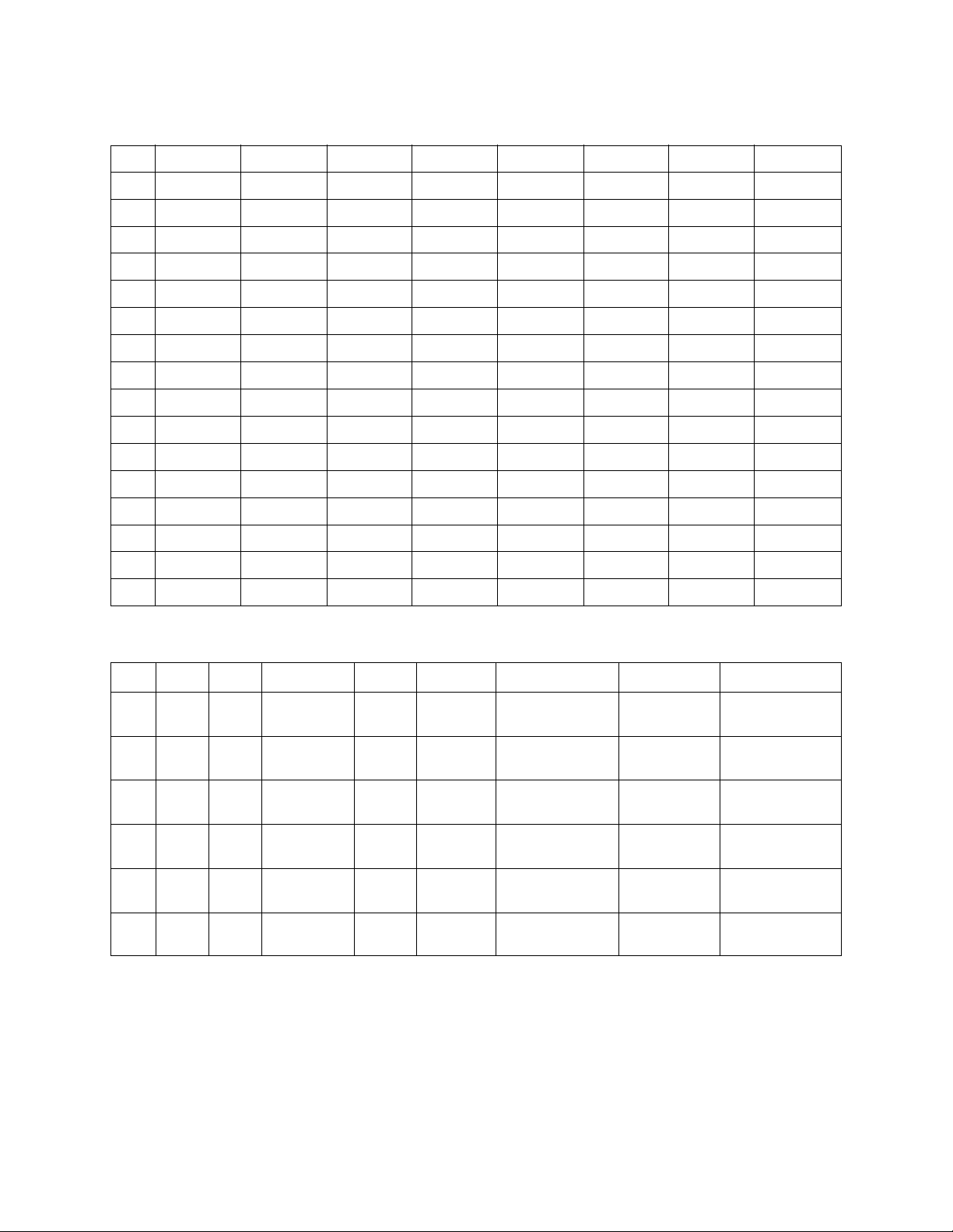
N Item Code No. Part Name Specification Q
Main PCB
N 1 10123432 PCB ASSY/MA1M TK-RJM502974*001 1 DL A
N IC1 10122996 IC TC74HCT08AF(EL) 1 AB C
IC10 10054502 LSI UPD914AGM-3ED 1 CK B
IC11 21056621 IC TC74LCX138FT(EL) 1 AF C
IC13 20125987 LSI TC190C020AF-001 1 BC B
N IC16 10122999 IC TC74LCX00FT(EL) 1 AB C
N IC2,12 10126397 LSI CY62128VLL-70ZAIT 2 AX B
IC3 20125495 IC UPD6379LGR-E1 1 AO C
IC4 69320063 IC R1151N001C-TR 1 AF C
N IC5 10122526 LSI LH28F160BJHE-BTL90 1 BD B
IC6 21054158 IC TA75S393F(TE85L) 1 AC C
N IC7 10123005 IC TC7WH123FU(TE12L) 1 AF C
N IC8 10129990 LSI MR27V6402G03FTNZ04 1 BQ B
D2,8,9 23901820 DIODE 1SS355TE-17 3 AA C
D3-6 27752079 DIODE DA227-TL 4 AA C
Q1 22510672 TRANSISTOR 2SB1548-P,CS 1 AD C
Q2 22521169 TRANSISTOR 2SC4081T106S 1 AA C
Q3-8 22500847 TRANSISTOR DTC143ZS-TP 6 AA C
L7,8 30132548 FUSE CHIP BLM21A102SPT 2 AA C
L1-5 30450235 FUSE CHIP BLM11A102SPT 5 AA C
X1 10059360 OSCILLATOR/CRYSTAL SMD-49-16.384M 1 AI C
Sub PCB
N 2 10123433 PCB ASSY/MA2M TK-RJM502976*001 1 CL A
IC201 10062671 IC LA4636 1 AV B
IC202,203 21210072 IC NJM2068DD 2 AD B
D201,202 23903021 DIODE SRT14 2 AF C
D203,207,
208,210
D204 10038115 DIODE MTZJT-775.6B 1 AA C
D205 10025044
D209 21141421 IC/PHOTO COUPLER PC900V 1 AK C
Q201,203,
205-207
Q202 22501591 TRANSISTOR 2SB1237TV2R 1 AB C
Q204 10047397 TRANSISTOR 2SD1913S 1 AD C
J201 19150373 JACK HEC2305-01-330 1 AB C
J202 36120665 JACK/PHONE JYB21-5006 1 AG C
J203 36120789 JACK YKB21-5010 1 AC C
J204 35014816 JACK/DIN YKF51-5051 1 AH C
L202,204,205 10056228 COIL R2318-RB53-856397 3 AB C
L203,206 10057360 COIL R2318-RB53-856396 2 BB C
N 3 10123429 PCB ASSY/CN1M TK-RJM502971*001 1 AZ B
N 4 10123430 PCB ASSY/CN2M TK-RJM502972*001 1 BA B
N 5 10123431 PCB ASSY/CN3M TK-RJM502973*001 1 BE B
D301 10104646 LED 1154HD-B5/10-90 1 AA C CN1M
N D302 10122221 LED 1154GD-B5/10-90 1 AA C CN1M
N D303 10122220 LED 1154GD-B5/9.5-90 1 AA C CN1M
N D304 10122219 LED 1154GD-B5/9-90 1 AD C CN1M
N D305 10122218 LED 1154GD-B5/7.5-90 1 AA C CN1M
N D306,307 10116376 LED SLR343BBT3F 2 AJ C CN3M
N VR303 10122556 VAERIABLE R RK09K12C0D1A 1 AL C CN2M
23153132 DIODE 1SS133T-77 4 AA C
DIODE MTZJT-776.2A
22501627 TRANSISTOR 2SC1740STPS 5 AA C
Console PCBs
Notes : Q - Quantity per unit
R - Rank
Price
Code
1AAC
R Remark
— 24 —
Page 27

N Item Code No. Part Name Specification Q
LCD PCB
N 6 10123434 PCB ASSY/LCD1M TK-RJM502998*001 1 BE C
IC501 10006502 LSI ML9040-B02GA 1 AU C
Keyboard PCBs
7 10053891 PCB ASSY/KY1M M140687*9 1 BK B
D501-564 23010101 DIODE 1S2473T-77-T 64 AA C
8 10053893 PCB ASSY/KY2M M140688*9 1 BJ B
D565-622 23010101 DIODE 1S2473T-77-T 58 AA C
Keyboard Unit
9 69222720 KEY SET/LT WHITE M312118*1 4 AP B
10 69222730 KEY SET/LT WHITE M312118*2 1 AR B
11 69068481 KEY SET/LT BLACK 10P M140369A-3 2 AS B
12 69068591 KEY SET/LT BLACK 5P M140369A-4 1 AF B
13 69222762 RUBBER/KEY M211704B-1 4 AF C
14 69222772 RUBBER/KEY M211705B-1 1 AF C
Panel Unit
15 69306970 COVER/BATTERY M341235*3 1 AT C
16 69273030 PACKING M440775-1 2 AA C
N 17 10123844 KNOB/ROTARY RJM502503-001V01 1 AA C
N 18 10123847 PANEL/DISPLAY RJM502491-001V01 1 AU C
N 19 10123897 BL ASSY TK-RJM502643*001 1 BB C
20 10116367 REFLECTOR RJM502392-001V01 1 AC C
N 21 10128631 RUBBER/KEY/A RJM502492-001V01 1 AA C
N 22 10123853 RUBBER/KEY/B RJM502493-001V01 1 AE C
N 23 10123855 RUBBER/KEY/C RJM502494-001V01 1 AB C
N 24 10123859 RUBBER/KEY/D RJM502495-001V01 1 AE C
N 25 10123862 RUBBER/KEY/E RJM502496-001V01 1 AC C
N 26 10123864 RUBBER/KEY/F RJM502497-001V01 1 AC C
N 27 10123867 RUBBER/KEY/G RJM502498-001V01 1 AB C
N 28 10123870 RUBBER/KEY/H RJM502499-001V01 1 AC C
N 29 10123872 RUBBER/KEY/J RJM502500-001V01 1 AB C
N 30 10123873 RUBBER/KEY/K RJM502501-001V01 1 AA C
N 31 10123875 RUBBER/KEY/L RJM502502-001V01 1 AE C
32 10128521 LCD TR8262N 1 AB C
N 33 10116369 PLATE/BACK LIGHT RJM502395-001V01 1 AJ C
34 10081190 PIECE/TOP RJM501982-001V01 1 AA C
35 10081189 FILM RJM501963-001V01 1 AA C
N 36 10111048 CONNECTOR RJM502397-001V01 2 AE C
37 69224480 STOPPER M412324-1 1 AE C
N 38 10127636 SPEAKER S12JA07A 2 BB C
N 39 10123878 LABEL/RATING M341248-029V01 1 AA X
Accessary
10107083 STAND/MUSIC M141071-5 1 AW C
10038113 AC ADAPTOR AD-5UL-TC2(D) 1 BQ C Japan only
Refurbish
N R-1 10123894 PANEL SUB ASSY TK-RJM502642*001 1 CP X
N R-2 10123887 CASE SUB ASSY/MIDDLE TK-M141274*013 1 BB X
R-3 69069252 PLATE / BOTTOM M240573-2 1 AS X
Notes : Q - Quantity per unit
R - Rank
Price
Code
R Remark
— 25 —
Page 28

Ver.1 : Dec. 2005
Replacement of the PARTS LIST (P25)
Ver.2 : Sep. 2006
Replacement of the PARTS LIST (P25)
CASIO COMPUTER CO.,LTD.
Overseas Service Division
6-2, Hon-machi 1-Chome
Shibuya-ku, Tokyo 151-8543, Japan
 Loading...