

Page 1
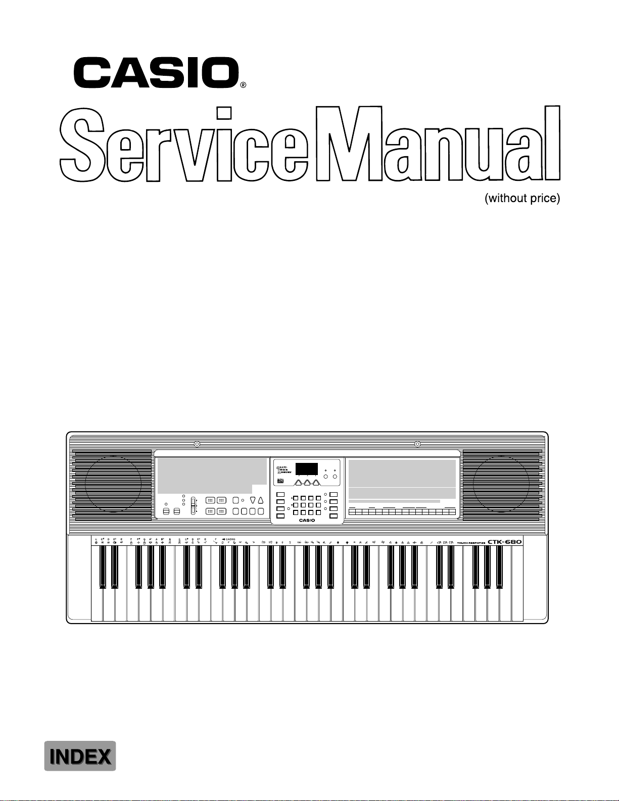
CTK-680
GM SOUND KEYBOARD
CTK-680
Page 2

CONTENTS
Specifications . . . . . . . . . . . . . . . . . . . . . . . . . . . . . . . . . . . . . . . . . . 2
Block Diagram . . . . . . . . . . . . . . . . . . . . . . . . . . . . . . . . . . . . . . . . . . 4
Circuit Description . . . . . . . . . . . . . . . . . . . . . . . . . . . . . . . . . . . . . . . 5
Major Waveforms . . . . . . . . . . . . . . . . . . . . . . . . . . . . . . . . . . . . . . . 15
Printed Circuit Boards . . . . . . . . . . . . . . . . . . . . . . . . . . . . . . . . . . . . . 16
Schematic Diagrams . . . . . . . . . . . . . . . . . . . . . . . . . . . . . . . . . . . . . 17
Exploded View . . . . . . . . . . . . . . . . . . . . . . . . . . . . . . . . . . . . . . . . . 21
Parts List . . . . . . . . . . . . . . . . . . . . . . . . . . . . . . . . . . . . . . . . . . . . . . 23
SPECIFICATIONS
GENERAL
Model: CASIO CTK-680
Keyboard: 61-key, 5-octave standard size keyboard with touch response (three sensi-
tivity levels and OFF setting)
Tones: 128 tones (Conform with General MIDI level 1) + 8 drum sounds with split/
layer features.
Polyphony: 32 notes maximum
Digital effects: 10
REVERB 1, REVERB 2, REVERB 3, CHORUS, TREMOLO, PHASE
SHIFTER, ORGAN SPEAKER, ENHANCER, FLANGER, LOUDNESS
Musical pads: 120 (four pads × 30 sets)
Phrases (22 sets), drums/percussion (7 sets), controller (1 set)
Phrases matche chord
Demo tunes: 3, sequential repeat playback
Auto-accompaniment
Rhythm patterns: 100
Tempo: Adjustable (216 levels, q = 40 to 255)
Chords: 3 types (CASIO Chords, Fingered, Full-Range Chords)
Parts: Rhythm, bass, Chord 1, Chord 2, Chord 3 (adjustable on/off, tone, volume,
pan, effect send, fine tune, coarse tune, expression settings)
Others: Intro, Normal Fill-in, Variation Fill-in, Synchro/Ending
Magical presets: 50 types (Break Beat, Melodycomp, Shadow Drum, Free Session)
Registration memory: 10
Tone changes, tempo setting, auto-accompaniment volume setting, mode,
layer on/off, Mixer settings, effect type, split on/off, rhythm type, autoaccompaniment rhythm assignment, pad type, chord fingering method,
touch response setting, MIDI settings (including assignable jack settings),
Magical Preset type
Mixer
Number of channels: 16
Parameters: TONE, VOLUME, PAN, EFFECT SEND, FINE TUNE, COARSE TUNE,
EXPRESSION
Multi-track memory
Number of songs: 2
Tracks: 6 (tone, volume, auto accompaniment, magical presets, pan, effect send, fine
tune, coarse tune, expression)
Type: Real-time
Capacity: Approximately 5,200 notes
— 2 —
Page 3

Other functions
Transpose: 25 levels (1 octave lower C to 1 octave upper C)
Tuning: Adjustable: A4 = 440 Hz ± 50 cents
Pitch Bender: Adjustable range: ± 12 semitones (bend up, bend down, bend saw) using
musical pads
Modulation: Vibrato setting and performances are done by a Musical pad.
MIDI: 16-timbre multi-timbre receive (General MIDI Level 1)
Speakers: 12 cm diameter × 2 (output: 2.5 W + 2.5 W)
Input/Output Jacks
Power supply: 9 V DC
Headphones: Stereo mini jack
Output jacks: Output impedance: 120 Ω
Output voltage 4.2 V (RMS) MAX
Assignable Jack: Standard jack (sustain, sostenuto, soft, rhythm start/stop)
MIDI terminals: IN, OUT
Power supply: 2-way
Batteries: Six D-size batteries
Battery life: Approximately 5 hours on R20P (SUM-1) manganese batteries
AC adaptor: AD-5 (optional)
Auto power off: Approximately six minutes after last key operation under battery power
(disabled when AC adaptor is connected).
Power consumption: 9 V --- 7.7 W
Dimensions: 94.2 × 36.7 × 13.5 cm (31-7/16 × 14-1/2 × 4-3/8 inches)
Weight: 5.2 kg (11.7 lbs) excluding batteries
ELECTRICAL
Current drain with 9 V DC:
No sound output 320 mA ± 20%
Maximum volume
with 12 polyphonic notes in tone No. 022 960 mA ± 20%
Volume; maximum
Phone output level (Vrms with 8 Ω load each channel): Left channel 115 mV ± 20%
with key C6 pressed in tone No. 042
Line output level (Vrms with 47 kΩ load each channel): Left channel 1280 mV ± 20%
with key C5 pressed in tone No. 042
Minimum operating voltage: 5.75 V
— 3 —
Page 4
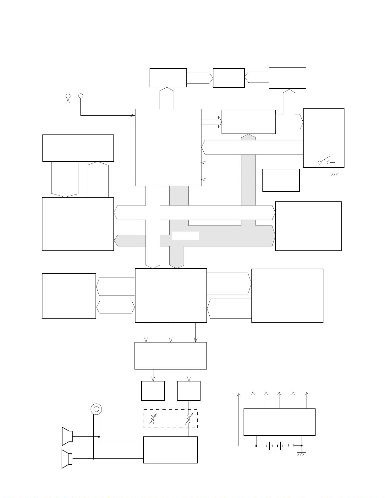
BLOCK DIAGRAM
LC1 ~ LC4, LC8
MIDI
IN
OUT
Keyboard
FI0 ~ FI7
SI0 ~ SI7
Key Controller
LSI16
HG52E35P
KC0 ~
KC7
A0 ~ A2
LED Driver
Q15 ~ Q18
LD0 ~
LD7
CPU
LSI14
HD6433294A33F
D0~D7
La ~ Lg, Lp
A0 ~
A14
A0 ~ A14
7-seg. LED
KOC
KOD
CLK
NMI
RES
LEDs
Gate Array
LSI17
UPD65611GB-019
KI1 ~ KI4
LED Driver
IC301
BA612
KO1 ~ KO4, KO8
KO0 ~
KO9
Reset IC
IC13
RH5VL36AA
Working Storage RAM
(256K-bit)
TC55257DFL-70L
Buttons
Power Switch
LSI15
Effect RAM
(256K-bit)
LSI13
LC33832M-70
Speakers
EA0 ~ EA14
ED0 ~ ED7
Output
A0 ~ A3
DSP
IC11
HG51B155FD
WCK1 SLOP BCK
D/A Converter
IC11
UPD6376GS
Filter
Q208
Main
Volume
Power Amplifier
IC202
LA4598
Filter
Q207
RA0 ~ RA20
RD0 ~ RD15
VC
Sound Source ROM
(24M-bit)
LSI12
MX23C2410MC-12CA54
LVDD
VCC
Power Supply Circuit
IC203, Q201 ~ Q206
DVDD
AVDD
VDD
— 4 —
Page 5
CIRCUIT DESCRIPTION
KEY MATRIX
KC0 KC1 KC2 KC3 KC4 KC5 KC6 KC7
FI0 C2 (1) C#2 (1) D2 (1) D#2 (1) E2 (1) F2 (1) F#2 (1) G2 (1)
SI0 C2 (2) C#2 (2) D2 (2) D#2 (2) E2 (2) F2 (2) F#2 (2) G2 (2)
FI1 G#2 (1) A2 (1) A#2 (1) B2 (1) C3 (1) C#3 (1) D3 (1) D#3 (1)
SI1 G#2 (2) A2 (2) A#2 (2) B2 (2) C3 (2) C#3 (2) D3 (2) D#3 (2)
FI2 E3 (1) F3 (1) F#3 (1) G3 (1) G#3 (1) A3 (1) A#3 (1) B3 (1)
SI2 E3 (2) F3 (2) F#3 (2) G3 (2) G#3 (2) A3 (2) A#3 (2) B3 (2)
FI3 C4 (1) C#4 (1) D4 (1) D#4 (1) E4 (1) F4 (1) F#4 (1) G4 (1)
SI3 C4 (2) C#4 (2) D4 (2) D#4 (2) E4 (2) F4 (2) F#4 (2) G4 (2)
FI4 G#4 (1) A4 (1) A#4 (1) B4 (1) C5 (1) C#5 (1) D5 (1) D#5 (1)
SI4 G#4 (2) A4 (2) A#4 (2) B4 (2) C5 (2) C#5 (2) D5 (2) D#5 (2)
FI5 E5 (1) F5 (1) F#5 (1) G5 (1) G#5 (1) A5 (1) A#5 (1) B5 (1)
SI5 E5 (2) F5 (2) F#5 (2) G5 (2) G#5 (2) A5 (2) A#5 (2) B5 (2)
FI6 C6 (1) C#6 (1) D6 (1) D#6 (1) E6 (1) F6 (1) F#6 (1) G6 (1)
SI6 C6 (2) C#6 (2) D6 (2) D#6 (2) E6 (2) F6 (2) F#6 (2) G6 (2)
FI7 G#6 (1) A6 (1) A#6 (1) B6 (1) C7 (1)
SI7 G#6 (2) A6 (2) A#6 (2) B6 (2) C7 (2)
Note: Each key has two contacts, the first conatct (1) and second contact (2).
Key
FI
Second contact (2)
First contact (1)
KC
SI
— 5 —
Page 6
NOMENCLATURE OF KEYS
C#2
F#2D#2
C#3A#2G#2
D#3
F#3 G#3
A#3 C#4 D#4
F#4 G#4
A#4
C#5
D#5
F#5 G#5
A#5
C#6
G#6F#6D#6
A#6
C2 D2E2F2G2A2 B2 C3 D3
BUTTON MATRIX
KO0 MODE PAD A PAD B PAD D
KO1 TEMPO UP TEMPO DOWN START/STOP PAD C
KO2 RHYTHM TONE
KO3
KO4 DEMO
KO5
KO6 987+
MAGICAL
PRESET
SYNCHRO/
ENDING
E3
F3 G3 A3 B3 C4 D4 E4 F4 G4 A4 B4 C5 D5 E5 F5 G5 A5 B5
C6
KI1 KI2 KI3 KI4
LAYER SPLIT
TOUCH
RESPONSE
DIGITAL EFFECT REGISTRATION
VAR/FILL-IN NORMAL/FILL-IN INTRO
B6A6G6F6E6D6
C7
KO7 —456
KO8
ACCOMP
VOLUME
MULTI-TRACK
MEMORY
TRANSPOSE/
TUNE/MIDI
MIXER
KO9 0123
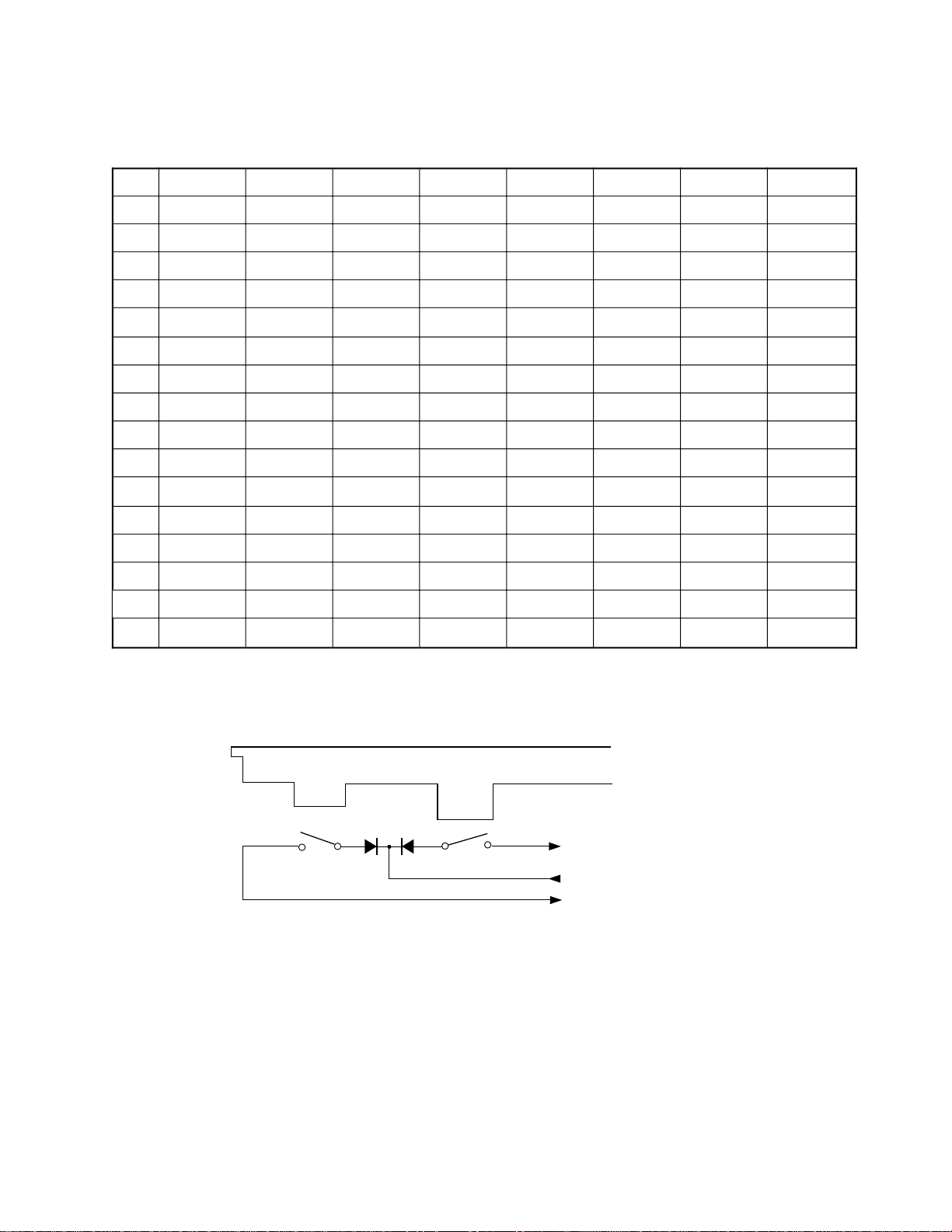
POWER SUPPLY CIRCUIT
The power supply circuit generates six voltages as shown in the following table. VDD voltage is always
generated. The others are controlled by APO signal output from the CPU.
Name Voltage For operation of
VDD +5.0 V CPU, Reset IC, Working storage RAM, Gate array
DVDD +5.2 V DSP, Key controller, Sound source ROM, Effect RAM
AVDD +5.0 V DAC, Filter
LVDD +5.0 V LED Driver
VCC +12 V Pilot lamp
VC +12 V Power amplifier
— 6 —
Page 7
CPU (LSI14: HD6433294A33F)
The 16-bit CPU contains a 32k-bit ROM, a 1k-bit RAM, seven 8-bit I/O ports, an A/D convertor and MIDI
interfaces. The CPU gains access to the working storage RAM, the DSP and the key controller. The CPU
interprets MIDI message using the working storage RAM. The CPU also controls buttons and LEDs.
The following table shows the pin functions of LSI14.
Pin No. Terminal In/Out Function
1 P50/TXD Out MIDI signal output
2 P51/RXD In MIDI signal input
3 P52/SCK Out Reset signal output
4 -RESET In Reset signal input
5 -NMI In Power ON trigger signal input
6 VCC In +5 V source
7 -STBY In Standby signal input. Connected to +5 V.
8 VSS In Ground (0 V) source
9, 10 XTAL, EXTAL In 16 MHz clock input
11, 12 MD1, MD0 In Mode selection input
13 AVSS In Ground (0 V) source
14 P70 In Analog input terminal for the pitch bend wheel
15 ~ 21 P71 ~ P77 Ou t Input terminals from keys (KI1 ~ KI7)
22 AVCC In +5 V source
23 ~ 30 P60 ~ P67 Out LED drive signal output
31 VCC In +5 V source
32 ~ 48 A0 ~ A15 O ut Address bus
40 VSS In Ground (0 V) source
49 ~ 56 D0 ~ D7 In/Out Data bus
57 P40 Out KO signal data
58 P41 Out Clock for KO signal generator
5 9 P42 Out APO signal output
60 P43 Out Read enable signal output
61 P44 In Write enable signal output
6 2 P4 5 — Not used
63 P46 Out 16 MHz clock output
6 4 P 47 — Not used. Connected to +5 V source.
DIGITAL SIGNAL PROCESSOR (LSI11: HG51B155FD-1)
Upon receipt of note numbers and their velocities, the DSP reads sound and velocity data from the sound
source ROM in accordance with the selected tone; the DSP can read rhythm data simultaneously when a
rhythm pattern is selected. Then it provides 16-bit serial signal containing data of the melody, chord,
bass, and percussion to the DAC. When an effect is selected, the DSP adds the effect to the sound data
using a 256k-bit RAM.
The following table shows the pin functions of LSI11.
— 7 —
Page 8
Pin No. Terminal In/Out Function
1 ~ 8 CD0 ~ CD7 In/Out Data bus
9, 10 CE1, TRSB — Not used
11 GND7 In Ground (0 V) source
12 CK16 Out Terminal for 24.576 MHz clock check point
13 VCC6 In +5 V source
14 CK0 In Clock input. Connected to terminal CK16.
1 5 TCKB — Not used
16 VCC1 In +5 V source
17 GND1 In Ground (0 V) source
18, 19 XT0, XT1 In/Out 24.576 MHz clock input/output
20 SGL In System control terminal. Single chip system: Open
21 CCSB In Chip select signal input
22 ~ 25 CA0 ~ CA3 In Address bus
2 6 CE0 In Not used. Connected to ground.
27 CWRB In Write enable signal
28 CRDB In Read enable signal
29 ~ 32 — — Not used
33 RESB In Reset signal input
34 TESB In Not used. Connected to +5 V.
35 ~ 39 — — Not used
40 ~ 49
52 ~ 57
RD0 ~ RD15 Data bus for the sound source ROMIn
50 VCC2 In +5 V source
51 GND2 In Ground (0 V) source
58 RA23 Out Not used
59 RA22 Out Chip select signal for the sound source ROM
60 RA21 Out Not used
61 ~ 73
75 ~ 82
RA0 ~ RA20 Address bus for the sound source ROMOut
74 GND5 In Ground (0 V) source
8 3 WOK2 Out Not used
84 VCC3 In +5 V source
85 GND3 In Ground (0 V) source
86 WOK1 Out Word clock for the DAC
87 SOLM O u t Not used
88 SOLP Out Serial sound data output
8 9 BO K O u t Bit clock output
90 ~ 92 — — Not used
93 VCC5 In +5 V source
94, 95
97 ~ 105
107, 109
EA0 ~ EA14 Address bus for the effect RAMOut
110, 112
96 EWEB Out Write enable signal for the effect RAM
— 8 —
Page 9

Pin No. Terminal In/Out Function
106 EOEB Out Read enable signal output for the effect RAM
108 VCC7 In +5 V source
11 1 ECEB Ou t Chip select signal output for the effect RAM
113 ~ 117 ED11 ~ ED15 — Not used
118 VCC4 In +5 V source
119 GND4 In Ground (0 V) source
120 ~ 122 ED8 ~ ED10 — Not used
123 ~ 130 ED0 ~ ED7 In/Out Data bus for the effect RAM
131 GND6 In Ground (0 V) source
132 ~ 134 — — Not used. Connected to ground.
135, 136 — — Not used
Block diagram of DSP and DAC circuit
Sound Source ROM
LSI12
MX23C2410MC-12CA54
CE
A0 ~ A20 Q0 ~ Q15
RA22
RA0 ~
RA20
RD0 ~
RD15
SOLP: Sound data
BOK: Bit clock
WOK1: Word clock
From CPU
UPD65611GB
D0 ~ D7
A0 ~ A3
Gate Array
LSI17
RESET
LSIB
RDAB
WRAB
RESB
CRDB
CCSB
CWRB
ECEB EOEB
CS
HG51B155FD-1
OE
Effect RAM (256K-bit)
LC33832M-70-TLM
WE
DSP
LSI11
EWEB
LSI13
ED0 ~
ED7
I/01 ~ I/08
EA0 ~
EA14
A0 ~ A14
SOLP
BOK
WOK1
DAC
IC11
SI
CLK
LRCK
UPD6376GS
PG
X11
24.576 MHz
ROUT
LOUT
— 9 —
Page 10

DAC (IC11: UPD6376GS)
The DAC receives 16-bit serial data output from the DSP. The data contains digital sound data of the
melody, chord, bass, and percussion for the right and left channels. The DAC converts the data into
analog waveforms by each channel and output them separately.
The following table shows the pin functions of IC11.
Pin No. Terminal In/Out Function
1 SE L In Mode selection terminal. Connected to ground.
2 D.GND In Ground (0 V) source for the internal digit circuit
3 NC — Not used
4 DVDD In +5 V source for the internal digital circuit
5 A.GND In Ground (0 V) source for the right channel
6 R.OUT Ou t Right channel sound waveform output
7, 8 A.VDD In +5 V source for the internal analog circuit
9 R.REF In Right channel reference voltage terminal
1 0 L.REF In Left channel reference voltage terminal
1 1 L.OUT Out Left channel sound waveform output
12 A.GND In G round (0 V) source for the left channel
1 3 LRCK In Word clock input
14 LRSEL In Not used. Connected to ground.
1 5 SI In Sound data input
16 CLK In Bit clock input
KEY CONTROLLER (LSI16: HG52E35P)
The key controller generates key scan signals and provides them to the keyboard. By counting the time
between first-key input signal FI and second-key SI from the keyboard, the key controller detects key
velocity. The note number and its velocity data are read at regular intervals by the CPU.
Key Controller
LSI16
HG52E35P
CRDB
CWRB
CKI
CCSB
RESB
CD0
~
CD7
CA0 ~ CA2
SI0
SI7
KC0
Key scan signal
~
KC7
FI0
Key input signal
FI7
Keyboard
KC
First contact
FI
SI
Second contact
LSI17
µPD65611GB
Data bus
Address bus
RDAB
WRAB
CLKA
HGB
RESET
— 10 —
Page 11

The following table shows the pin functions of LSI16.
Pin No. Terminal In/Out Function
1 REQB Out Not used
2, 3, 60 ~ 63 In
FI8 ~ FI10,
Not used. Connected to +5 V.
SI8 ~ SI10
4 VCC In +5 V source
5 CRDB In Read enable signal input
6 CWRB In Write enable signal input
7 CCSB In Chip select signal input
8, 9, 1 1 T, STBY, W In Not used. Connected to +5 V.
10 RESB In Reset signal input
12 CKI In 16 MHz clock input
13, 14 TMD, TST In Not used. Connected to ground.
1 5 CKO O ut Not used
16 GND In Ground (0 V) source
1 7 XIN In Not used. Connected to ground.
18 XOUT Out Not used
1 9 TRES In Not used. Connected to ground.
20 ~ 23, 25 ~ 28 CD0 ~ CD7 In/Out Data bus
24 GND
In
Ground (0 V) source
29 ~ 31 CA0 ~ CA2 In Address bus
32 VCC In +5 V source
33 ~ 39, 41 ~ 43, FI0 ~ FI9,
In
Key input signal input
53 ~ 55, 57 ~ 63 SI0 ~ SI9
40 VCC In +5 V source
44 ~ 47, 49 ~ 52 KC0 ~ KC7 Out Key scan signal
48, 56 GND In Ground (0 V) source
64 VCC In +5 V source
— 11 —
Page 12

GATE ARRAY (LSI17: UPD65611GB)
The gate array provides chip enable signals for DSP, Key Controller, and Working Storage RAM. The LSI
also generates scan signals of the button switches with K0O and K0C signals from the CPU.
K0O
K0C
A4 ~ A15
From CPU
CLK
Gate Array
UPD65611GB
LSI17
Each pin function of the LSI is listed below.
KO0 ~ KO15
LSIB
WRAB
RDAB
HGB
CLKA
SAMPB
Button Switch
Matrix
CCSB
CWRB
CRDB
CWRB
CRDB
CCSB
CKI
CS
KI1 ~ KI4
To CPU
DSP
HG51B155FD
LSI11
Key Controller
HG52E35P
LSI16
Working Storage RAM
TC55257DFL-70L
LSI15
Pin No. Terminal In/Out Function
1 K0C In Primary signal for KO0 ~ KO15
2 APOB In APO signal from CPU
3 RDB In Read enable signal from CPU
4 WRB In Write enable signal from CPU
5 WRAB Out Write enable signal for DSP and Key Controller
6 CLK In Clock pulse from CPU
7 LSIB Out DSP chip select signal
8 RDAB Out Read enable to DSP and Key Controller
9 RESET Out DSP and Key Controller reset signal
10 LED1 — Not used
11 LED0 — Not used
12 ~ 16, 18 ~ 22 Out Button switch scan signalsKO0 ~ KO9
17 GND In Ground (0 V) source
2 3 NC — Not used
24 GND In Ground (0 V) source
25 CLKA Out 16 MHz Clock pulse for Key Controller
26 GND In Ground (0 V) source
27 HGB Out Key Controller chip select signal
— 12 —
Page 13
Pin No. Terminal In/Out Function
28 SAMPB Out Working Storage RAM chip select signal
29, 30 D0, D1 In Data bus
A4 ~ A1531 ~ 38, 40 ~ 43 In
Address bus
44 K0O In Clock pulse from CPU
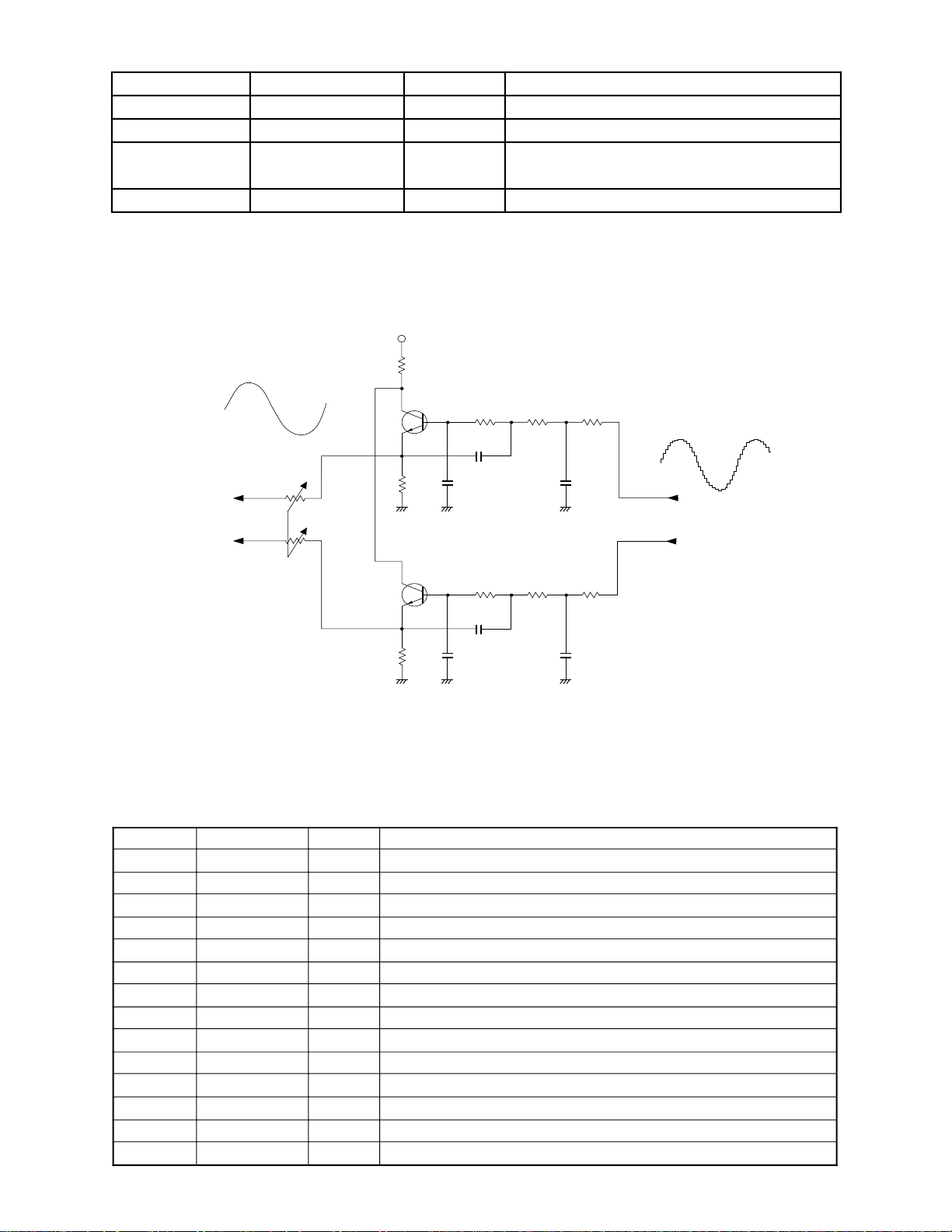
FILTER BLOCK
Since the sound signals from the DAC are stepped waveforms, the filter block is added to smooth the
waveforms.
AVDD
Ω R236
22
Q207
Main
Volume
2SC1740SR
2.2K
R249
AG
Q208
2SC1740SR
2.2K
R250
AG
R247
C242
C244
C152B
AG
R248 R246 R244
C243
C245
C152B
AG
R245 R243
1K 1K 1K
C223(H)
1K 1K 1K
C223[H]
C246
AG
C247
AG
C472B
From DA ConverterTo Power Amp.
C472B
POWER AMPLIFIER (IC202: LA4598)
The power amplifier is a two-channel amplifier with standby switch.
The following table shows the pin function of IC202.
Pin No. Terminal In/Out Function
1 Power GND In Ground (0 V) source
2 Ch1 B.S. — Terminal for a bootstrap capacitor
3 Ch1 OUT Out Channel 1 output
4 VCC In +9 V source
5 Ch1 N.F. In Negative feedback input
6 Ch1 IN In Channel 1 input
7 D.C. — Terminal for a decoupling capacitor
8 Pre GND In Ground (0 V) source
9 Stand by In Power control signal input. 0 V: Off, +9 V: On
10 Ch2 IN In Channel 2 input
11 Ch2 N.F. In Negative feedback input
12 Ch2 OUT Out Channel 2 output
13 Ch2 B.S. — Terminal for a bootstrap capacitor
14 NC — Not used
— 13 —
Page 14

LED DRIVING
LVDD
La ~ Lg, Lp
LD0 ~ LD7
CPU
Q15 ~ Q18
LSI14
HD6433294A33F
LC1
LC8
IC301
BA612
LED Driver
LG
UPD65611GB-019-3BA
KO0 ~ KO3, KO5
LED Driver
IC17
P40
P41
Gate array
RESET CIRCUIT
When batteries are set or an AC adapter is connected, the reset IC provides a low pulse to the CPU. The CPU
then initializes its internal circuit.
When the power switch is pressed, the CPU receives a low pulse of POWER signal. The CPU provides APO
signal to the power supply circuit and raises RESET signal to +5 V to reset the DSP, the key controller and
the gate array.
Battery set
VDD
RESET
Reset IC
IC13
RH5VL36AA
POWER
From power switch
APO
To power supply circuit
VDD
CPU
LSI14
HD6433294A33F
-NMI
P42
UPD65611GB-019-3BA
-RESET
Working Storage RAM
TC55257DFL-70L
Gate Array
LSI17
LSI15
DVDD
VDD
DVDD
DSP
LSI11
HG51B155FD-1
DVDD
Key Controller
LSI16
HG52E35P
— 14 —
Page 15

MAJOR WAVEFORMS
1
3
B
E
F
C
D
4
5
9
0
A
2
6
7
8
CH1
CH1
CH1
CH2
CH2
CH3
CH2
CH1
CH3
CH1
CH2
CH3
CH2
CH1
CH2
CH3
CH1: 5 V
CH1: 5 V CH2: 5 V CH3: 5 VCH2: 5 V CH3: 5 V
CH1: 5 V CH1: 5 V CH2: 5 V CH3: 5 V
CH1: 5 V CH2: 5 V CH1: 20 mV CH2: 20 mV
˜˜
1 µs0.5
s
5 ms20 µs
0.5 s 1 µs
1 Voltage VDD
JG connector pin 8
2 Initial reset signal
RH5VL36A pin 1
3 Power ON signal NMI
JF connector pin 4
4 APO signal
JG connector pin 5
5 Reset signal
UPD65611GB-019-38A pin 9
6 Key scan signal KC0
HG52E35P pin 44
7 Key scan signal KC1
HG52E35P pin 45
8 Key scan signal KC2
HG52E35P pin 46
9 Button scan signal KO0
JF connector pin 6
0 Button scan signal KO1
JF connector pin 7
A Button scan signal KO2
JF connector pin 8
B Word clock WOK1
UPD6376GS pin 13
C Data S1 (Note OFF)
UPD6376GS pin 15
D Bit clock BOK
UPD6376GS pin 16
E Sound waveform (L)
JG connector pin 14
F Sound waveform (R)
JG connector pin 13
Tone: Whistle (No. 078)
Key: A4
Touch response: OFF
CH3: 5 VCH2: 5 V
— 15 —
Page 16

R124
R123
R122
R121
R120
R119
R118
R117
R116
R115
R114
R113
R112
R111
R110
R109
R108
R107
R106
R105
R104
R103
R102
R101
R100
R99
R98
R97
C55
C56
C57
C58
C59
C60
C61
C62
C63
C64
C65
C66
C67
C68
C69
C70
C47
C46
C45
C44
C43
C42
C41
C40
C39
C38
C49
C48
C50
C51
C35
C34
R26
C35
C34
R26
C78
C147
FB26
R12
R13
R14
C20
C21
C22
C23
C24
C30
C29
C26
R85
R86
R87
R88
R89
R90
C99
R91
R68C73
C71
C146
C81
C98
C103R96
R95
C141
C142
C80
FB52
FB51
LSI11
C76
R11
C54
IC12
Q14
D12
LSI15
LSI14
D11
Q13
C153 C152
EF2
C87
C133
R71
R94 C102
C101 R92
MR17
MR16
C143
R93
C84
C85
FB54
C94
C93
C100
FB55
R69
R81
R80
R79
R78
R160
R75
C149
C89
C150
R83
R82
C74
C140
C144
C25
C27
C28
C31
C32
C33
C77
C15C16
C14
Q11
Q12
C37
C11
C151
C12
JCM717-MA1M B
LSI16
C95
IC13
MR11
X12
X11
LSI17
C104
C105
C106
C107
C108
C109
C110
C111
C112
C113
C114
C115
C116
C117
C118
C119
C120
C121
C122
C123
C124
C125
C126
C127
C128
C129
C130
C131
JB
14
1
@
14
JA
1
D13
FB56
FB57
R84
R150
R67
C75
C13 R140
R27
Q15
C88
C91C90
C92
C132
D20
R74
R70
C97
MR14
MR12
R40
R39
R38
R37
R36
R35
R34
R33
R32
R31
R28
R29
R30
C52
FB25
FB24
C82
C79
C145
LSI12
LSI13
LC11
R22 R21
R25
R24
R23
FB15
FB14
FB13
FB12
FB11
FB20
FB19
FB17
FB16
FB18
FB21
FB22
FB23
C36
R41
R43
R42
EF1
C83
R18
R19
R20
R44
R45
R46
R47
R48
R49
R50
R51
R52
R53
R54
R55
R56
R57
R58
R59
R73
R72
C86
FB3736353433323130292839384041
42
FB4344454647484950
R60
R61
R62
R63
R64
R65
R66
NO.
JE16
JG15
1
1
JF15
Q16
Q17
Q18
1
1
4
6
7
8
11
2
12 13 14
10 9
3
5
PRINTED CIRCUIT BOARDS
MAIN PCB JCM717-MA1M
Top view
Bottom view
— 16 —
Page 17

MAIN PCB JCM717-MA1M
MA3M
MA3M
MA3M
MA3M
MA3M
MA3M
MA3M
MA3M
MA3M
MA3M
MA3M
MA3M
MA3M
MA3M
MA3M
MA3M
MA3M
MA3M
MA3M
MA3M
MA3M
MA3M
MA3M
MA3M
MA3M
MA3M
MA3M
MA3M
SCHEMATIC DIAGRAMS
14
13
12
5
1
15
4
16
6 7 8
2
3
10
9
11
— 17 —
Page 18

SUB PCB JCM716-MA2M
— 18 —
Page 19

CONSOLE PCB M716-CN1M
— 19 —
Page 20

KEYBOARD PCBs JCM617T-KY1M/KY2M
— 20 —
Page 21

R-1
EXPLODED VIEW
14
13
12
22
— 21 —
12
21
19
17
16
18
15
2
3
20
23
7
6
9
8
1
R-2
24
10
10
4
11
5
R-3
Page 22

PARTS LIST
CTK-680
Notes: This parts list does not include the cosmetic parts, which
parts are marked with item No. "R-X" in the exploded
view.
Contact our spare parts department if you need these
parts for refurbish.
1. Prices and specifications are subject to change without prior notice.
2. As for spare parts order and supply, refer to the
"GUIDEBOOK for Spare parts Supply", published
seperately.
3. The numbers in item column correspond to the same
numbers in drawing.
Page 23

Item Code No. Parts Name Specification Q R
Main PCB
1 6925 7090 Main PCB ass'y, M717-MA1M M140443*2 1 B
LSI2 2012 5159 LSI, ROM MX23C2410MC-12CA54 1 A
LSI3 2012 0777 LSI, RAM LC33832M-70-TLM 1 A
LSI7 2012 4298 LSI, UPD65611GB-019-3BA 1 A
LSI11 2012 1316 LSI, DSP HG51B155FD-1 1 A
LSI14 2012 5152 LSI, CPU HD6433294A33F 1 A
LSI15 2012 4291 LSI, RAM HM62256BLFP-7T 1 A
LSI16 2011 5194 LSI, Key controller HG52E35P 1 A
IC11 2114 4221 IC UPD6376GS-E1 1 A
IC12 2105 1120 IC TC7S08F-TE85R
IC13 2105 4536 IC RH5VL36AA-T1
Q11, Q12 2252 1169 Transistor, Chip 2SC4081-T106S
Q13, Q14 2250 1169 Transistor, Chip 2SA1576AT106S 2 B
Q15 - Q18 2259 2562 Transistor, Chip UMS1NTL 4 B
D11, D12
D13
X11
X12
2
IC201 2114 1421 IC, Photocoupler PC900V 1 B
IC202
IC203
Q201 2250 0742
Q203 2250 1577 Transistor 2SA933ASTPR 1 A
Q204 2250 1578
Q205 2251 0651
D201
D202
D203 2390 0371
D205 2360 2261 Diode, Zener RD5.1JSB3-T1-T
J201 3501 7049 Jack, Power HEC2305-01-330
J202 3612 0711 Jack, Phone YKB21-5101
J203 3612 0789 Jack YKB21-5010
J204 3501 4816 Jack, DIN YKF51-5051
VR201 2765 1344 Volume EWA-MJCC25B23
3 6925 7130 PCB ass'y M716-CN1M M140488*1
IC301 2114 3318 IC BA612
D301 - D337 2390 1344 Diode 1SS133T-77-T
LED301 2370 0952 LED, 7-segment LB-603VP1
LED308/390 2370 0959 LED LN882RPX-(TT)
4 6924 2580 PCB ass'y M617T-KY1M M140211*5 1
5 6924 2590 PCB ass'y M617T-KY2M M140212*5 1
6 6922 2720 White key set, LT M312118*1
7 6922 2730 White key set, LT M312118*2
2390 1820 Diode, Chip 1SS355TE-17
2390 2576 Diode, Chip, Schottky RB501V-40TE-17
2590 2107 Oscillator, Crystal HC-49S24A
2590 2079 Oscillator, Ceramic CSACS16.00MX040-TC
Sub PCB ass'y
6925 7120 Sub PCB ass'y M716-MA2,3M M140487*1
2114 2891 IC, Power amp. LA4598
205 2114 IC, Voltage regulator S-81350HG
Transistor
2220 1409 Transistor 2SC1740SR-TP-T
Transistor
Transistor
2390 1323 Diode RB100A-T32-T
2360 1134 Diode
Diode
2390 1344
Console PCBs
2370 0343 LED LN28RPX-(TT)
Keyboard PCBs
2301 0101 Diode 1S2473-T-77-T
2301 0101 Diode 1S2473-T-77-T 58
Keyboard unit
Notes: Q – Quantity per unit
Diode
R – Rank
2SA1703S,T-AN-T 1 A
2SC4483S,T-AN 1 A
2SB1274-CCC 1 A
RD5.1ESB1-T1-T 1 B
DSK10B-BT-T 1 B
1SS133T-77-T 3 C
37
64
A
1
A
1
2B
C
2
C
1
B
1
B
1
B
1
A
1
A
1
A
4
1B
1B
A
1
B
1
B
1
B
1
B
1
B
1
B
1
C
B
1
C
9
C
2
B
C
B
C
A
4
A
1
— 23 —
Page 24

Item Code No. Parts Name Specification Q R
8 6922 2740 Black key set 10P M111726-1
9 6922 2750 Black key set 5P M111726-2
10 6922 2761 Key contact rubber LT-CB M211704A-1
11 6922 2771 Key contact rubber LT-CS M211705A-1
Panel unit
12 3831 0357
13 6921 5040
14 6925 7210
15 6923 4980
16 6923 4990
17 6925 7250
18 6925 7260
19 6925 7270
Speaker
Slide knob
Display plate
Rubber button 711A
Rubber button 711B
Rubber button 711C
Rubber button 711F
Rubber button 711D
1221AF
M311860-1
M312128-3
M312122-2
M312123-2
M312124-3
M211727-5
M312125-6
20 6922 2660 Rubber button 710C M312088-1 1
21 6925 7280
22 6922 2680
23 6925 7290
Rubber button 711E
Rubber button 710D
Rubber button 711D
M312126-4
M312082-2
M312125-5
24 6906 8416 Battery cover M311164F*11 1
Accessory
6920 8691 Music stand M311760A-1
2A
A
1
A
4
A
1
B
2
B
1
C
1
B
1
B
1
B
1
B
1
B
1
B
B
1
B
1
B
1
B
1B
Notes: Q – Quantity per unit
R – Rank
— 24 —
Page 25

MA0100271A
 Loading...