


30HR070
Carrier 30HR070, 30HR100, 30HR080, 30HR090, 30HR110 Troubleshooting Manual
...
HEATING & COOLING
30HR,HS070-160
Flotronic Plus Reciprocating Liquid Chillers
Controls Troubleshooting Guide
Alf Model E Units Have Microprocessor Controls
and Electronic Expansion Valves
CONTENTS
SAFETY CONSIDERATIONS
Page
SAFETY
CONSlDERATlONS
................ 1
FLOTRONIC PLUS CONTROL SYSTEM ..... l-4
Generat ..................................... 1
Features .....................................
2
. PROCESSOR MODULE ...................
2
l LOW-VOLTAGE RELAY MODULE .........
2
. EXV
(ELECTRONK
EXPANSION
VALVE) DRIVER MODULE ...............
2
. KEYBOARD AND DISPLAY MODULE .....
2
. ELECTRONIC EXPANSION VALVE ........
3
l THERMISTORS ...........................
3
. CAPAClTY CONTROL ....................
3
CONTROL SEQUENCE .....................
4,5
Off Cycle ....................................
4
Start-Up ....................................
4
Capacity Control ............................
4
l SEQUENCE ...............................
4
Unit Shutdown ..............................
5
Complete Unit Stoppage
.....................
5
Single-Circuit Stoppage .....................
5
Lag Compressor Stoppage ...................
5
Restart Procedure ...........................
5
l GENERAL POWER FAlLURE ..............
5
l BLOWN FUSE
IN
POWER FEED
DISCONNECT ............................
5
l LOW WATER TEMPERATURE
CUTOUT..................................
5
l AUXILIARY INTERLOCK .................
5
l OPEN CONTROL
CIRCUlT
FUSE ..........
5
. FREEZE PROTECTION ....................
5
a HIGH-PRESSURE SWITCH ................
5
l LOSS OF CHARGE SWITCH ...............
5
. COMPRESSOR DISCHARGE
TEMPERATURE SWITCH .................
5
. OIL SAFETY SWITCH .....................
5
CONTROLS OPERATION .................. .5-l I
Accessing Functions and Subfunctions. ......
5
Qisplay Functions ...........................
5
a SUMMARY DISPLAY .....................
5
. STATUS FUNCTION ......................
5
. TEST FUNCTION ........................
10
Programming Functions
....................
1
I
.
SERVlCE
FUNCTION ....................
11
l SET POINT FUNCTION ..................
11
l SCHEDULE FUNCTION ..................
11
TROUBLESHOOTING .....................
12-26
Checking Display Codes ....................
12
l OPERATING MODE CODES ..............
12
. ALARM CODES
.........................
12
Quick Test .................................
14
Electronic Expansion Valves ................
19
l CHECKOUT PROCEDURE ...............
19
l EXV OPERATION ........................
21
Thermistors ................................
22
l LOCATION ..............................
22
l SENSOR REPLACEMENT ................
22
Modules ....................................
23
Installation, start-up and servicing of this equipment
can be hazardous due to system pressures, electrical
components and equipment location.
Only trained, qualified installers and service mechanics
should install, start-up and service this equipment.
When working on the equipment, observe precautions
in the literature, tags, stickers and labels attached to the
equipment and any
other
safety precautions that apply.
l Follow all safety codes.
0
Wear safety glasses and work gloves.
l Use care in handling, rigging and setting bulky
equipment.
l Use care in handling elcetronic components.
ELECTRII~ SHOCK HAZARD.
Open all remote disconnects before
servicing this equipment.
This unit uses a micreprocessor-based electronic
control system.
190
not use jumpers or other tools
to short out components, bypass or otherwise depart
from recommcndcd procedures. Any short-to-
ground of the control board or accompanying wiring
may destroy the electronic modules or electrical
component.
FLOTRONIC PLUS CONTROL SYSTEM
General
-
The 30HR,HS Flotronic Plus chillers
feature microprocessor-based electronic controls and an
electronic expansion valve (EXV) in each refrigeration
circuit.
The Flotronic Plus control system cycles compressors
and compressor unloaders to maintain the selected leav-
ing water temperature set point. It automatically positions the EXV to maintain the specified refrigerant
superheat entering the cylinders of the compressor.
Safeties are continuously monitored to prevent the unit
from operating under unsafe conditions. A scheduling
function, programmed by the user, controls the unit
occupied/ unoccupied schedule. The control also operates
a Quick Test program that allows the operator to check
input and output signals to the microprocessor.
The control system consists of a processor module
(PSIO), low-voltage relay module (DSIO), electronic
expansion valve (EXV), EXV driver module (DSIO),
keyboard and display module (HSIO) and thermistors to
provide analog inputs to the microprocessor. The soft-
ware resides in the PSIO.
-
Features
-
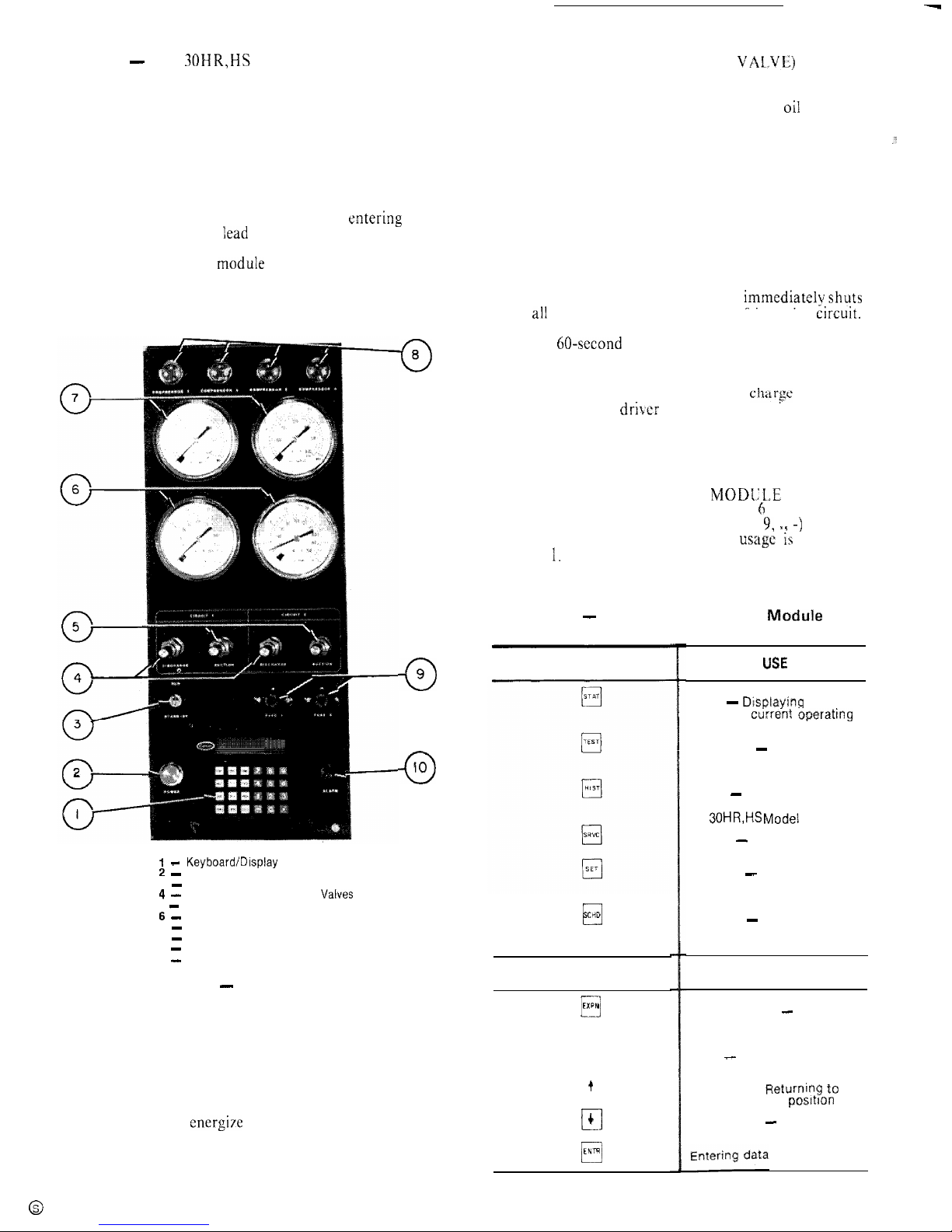
The 30HR,HS control panel is shown in
Fig. 1.
PROCESSOR MODULE - This module contains the
operating software and controls the operation of the
machine. It continuously monitors information received
from the various temperature thermistors and communicates with the relay module to increase or decrease the
active stages of capacity. The processor module also
controls the EXV driver module, commanding it to open
or close each electronic expansion valve in order to maintain approximately 20 F of superheat entering the
cylinders of each of the
Iead
compressors, Information is
transmitted between the processor module and the relay
module, EXV driver moduIe and keybuard display
module through a 3-wire communications bus.
0
8
0
9
0
IO
EXV (ELECTRONIC EXPANSION VALVE) DRIVER
MODULE -- The EXV driver module operates the electronic expansion valves (based on commands from the
processor) and monitors the status of the
oi1
pressure
switches and the refrigerant Ioss of charge switches.
If the loss of charge switch opens due to a low refrig-
.:.
erant charge, the EXV driver module detects a zero
voltage condition in the loss of charge switch electrical
circuit and communicates this information to the processor module. The processor module immediately shuts
down all compressors in the affected refrigeration circuit.
During operation, if the EXV driver module detects
zero voltage in the oil pressure switch electrical circuit
for 45 consecutive seconds (due to an open oil pressure
switch), it communicates this information to the processor module. The processor module immediatelvshuts
down ali compressors in the affected refrigeration circuit.
At start-up, if the oil pressure switch has not closed by the
end of a 60-second time period the EXV driver module
senses this and the processor module immediately shuts
down all compressors in the affected refrigeration circuit.
If a shutdown occurs due to loss of
cftarse
or low oil
pressure, the EXV driver module communicates this to
the processor module and the processor module locks the
compressors off in the affected refrigeration circuit.
The proper fault code(s) will appear on the display
whenever a safety switch opens.
KEYBOARD AND DISPLAY MODKLE - (Fig. 2)
This device consists of a keyboard with Cr function keys,
5 operative keys, 12 numeric keys (0 to 9, 11 -) and an
alphanumeric g-character LCD. Key
usage ii;
explained
in Table
1.
Table 1 - Keyboard and Display Madule
-
Key Usage
FUNCTION
KEYS
I - Keyboard/Display Module
2 -
Control Power ON Light
3 - RUN/STANDBY Switch
4 -
Discharge Pressure Gage
Valves
5 - Suction Pressure Gage Valves
6 -
Suction Pressure Gages
7 - Discharge Pressure Gages
8 - Compressor ON Lights
9 - Control Circuit Fuses
10
-
Alarm Light
0
SCHD
OPERATIVE
Fig. 1 - Control Panel
KEYS
El
EXPN
q
CLR
LOW-VOLTAGE RELAY MODULE -- This module
closes contacts to energize compressors, solenoid valves
and unloaders. It also senses the condition of the com-
pressor safeties and transmits this information to the
processor module.
q
t
El
4
0
ENTR
LOSE
Status - Displayjng diagnostic
codes and current operating
information about the machine
Quick Test - Checking inputs
and outputs for proper
operation
History - This key appears on
the keyboard, but is not used on
the 30HR,HS
Modei
E machines
Service - Entering specific
unit configuration information
Set Point - Entering operating
set points and day/time
information
Schedule - Entering occupied/
unoccupied schedules for unit
operation
USE
Expand Display - Displaying a
non-abbreviated expansion of
the display
Clear - Clearing the screen of
all displays
Up Arrow -
Rtjturnipg to
previous display posItIon
Down Arrow - Advancing to
next display position
2
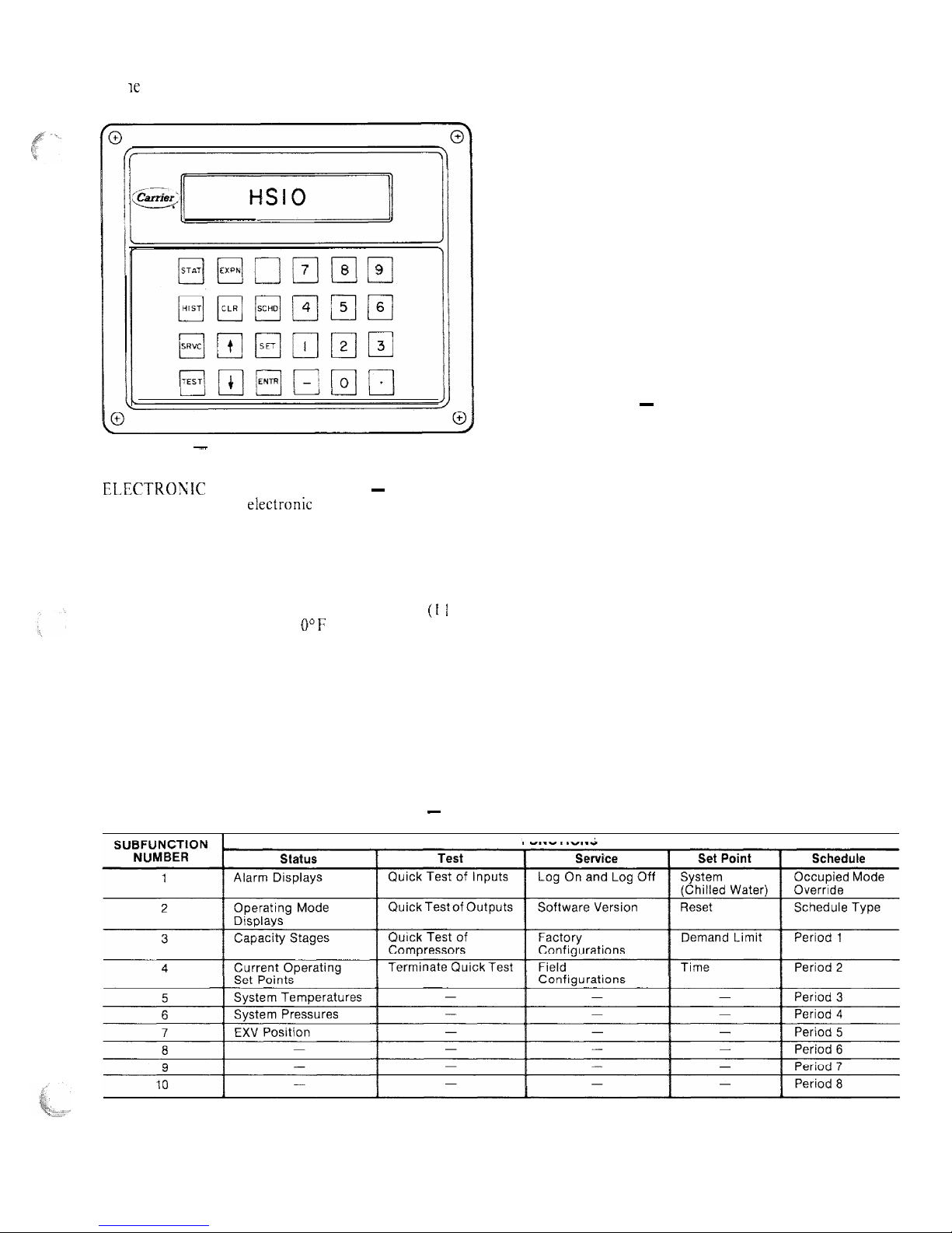
Each function has one or more subfunctions as shown At initial start-up the valve position is initialized to 0.
in Table 2. These functions are defined in greater detail After that, the microprocessor keeps accurate track of the
in t K Controls Operation section of this book.
Fig. 2 - Keyboard and Display Module
ELECTROWIC EXPANSION VALVE ~ The micro-
processor controls the electronic expansion valve through
the EXV driver module. Inside the expansion valve is a
linear actuator stepper motor. To control the stepper
motor’s position, the thermistor in the cooler and the
thermistor in the lead compressor in each circuit are used
to maintain a 20 F (1 I C) difference. Because the compressor sensor is after the compressor motor, which adds
approximately 15 F (8.3 C) superheat, the 20 F (1 I C)
control temperature results in
U”F
to 5 F (2.8 C) superheat leaving the cooler. This improves the performance of
the cooler.
valve position in order to use this information as input for
the other control functions.
The control monitors the superheat and the rate of
change of superheat to control the position of the valve.
The valve stroke is very large; this results in very accurate
control of the superheat.
The electronic expansion valve is also used to limit the
maximum saturated suction temperature to 55 F (12.8 C)
to keep from overloading the compressor during high
cooler water temperatures. This allows the unit to start
with very warm water temperatures.
THERMISTORS ~ The electronic control uses 7 thermistors to sense temperatures used to control the operation of the chiller. Sensors are listed in Table 3.
CAPACITY CONTROL ~ The control cycles compressors and alternately loads and unloads cylinders to
give capacity control steps as shown in Table 4. The unit
controls leaving chilled water temperature. Entering
water temperature is used by the microprocessor in determining the optimum time to load and unload, but is not a
control set point.
The chilled water temperature set point can be automatically reset by the return temperature reset or space
and outside air temperature reset features.
Table 2 - Function and Subfunctions
FUNCTIONS
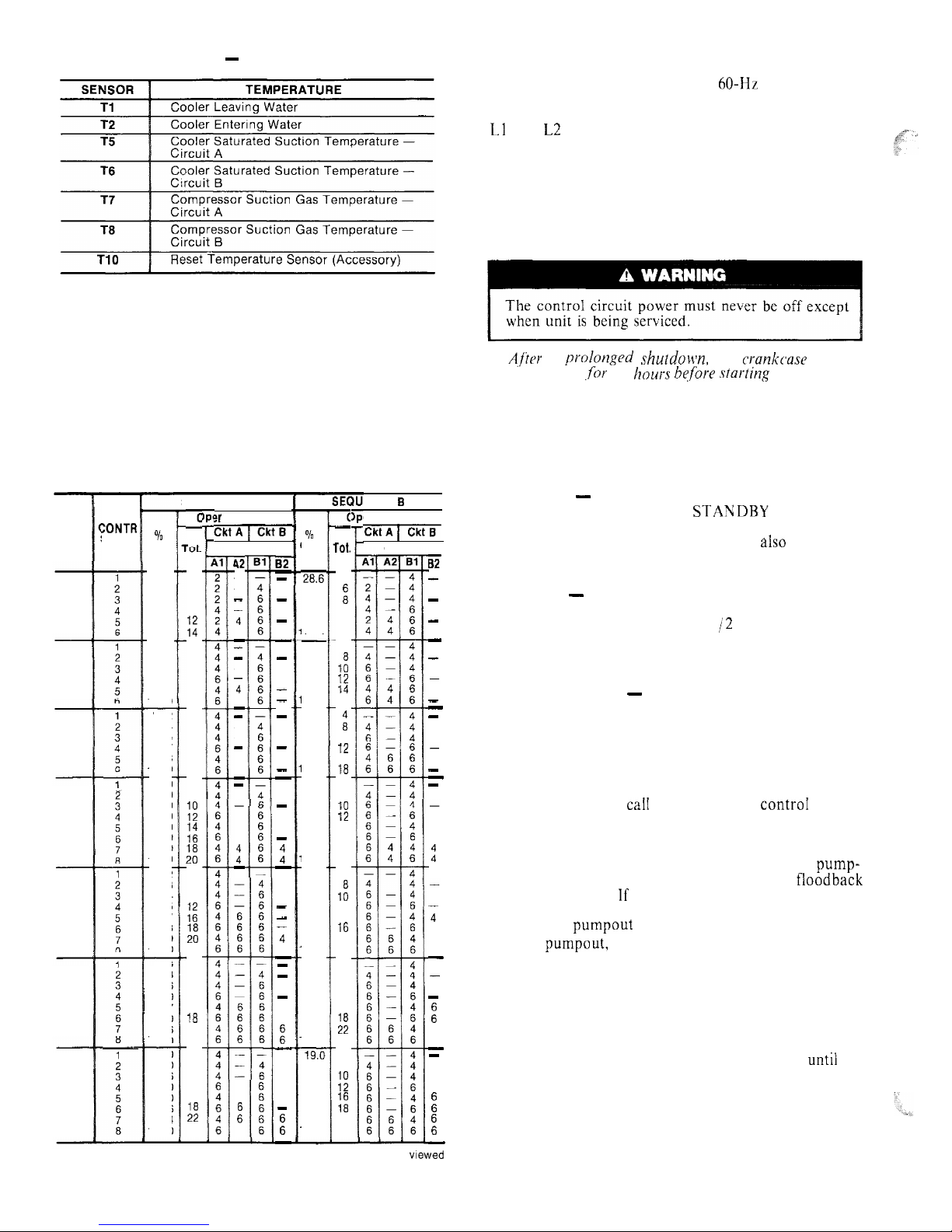
Table 3 - Thermistors
CONTROL SEQUENCE
The control power (115-l-60 for 60-Hz units; 230-l-50
for 50-Hz units) must be supplied directly from a separate
source through a code-approved fused disconnect to the
Ll
and L2 terminals of unit power teminal block.
NOTE: There is no switch or circuit breaker; only fuses. If
the control power feed is live, so is the circuit.
Crankcase heaters are wired into the control circuit.
They are always operative as long as control circuit
power is on even though unit may be off because of
safety device action. Heaters are wired so they are on only
when their respective compressors are cycled off.
A,f’tor
a prnlonged shutdoun, the
crankcause
heaters
should be on
,for
24
hours hqfbre starting
the unit.
When power is supplied to control circuit, unit is ready
for operation providing all safety devices are satisfied,
interlocks are closed and instructions on warning labels
have been followed.
If schedule function is used, refer to page 11 for details
on control operation.
Off Cycle - During unit off cycle when the RUN;
STANDBY switch is in the STANDBY position, the
crankcase heaters and the control system are energized.
The electronic expansion valves are
also
energized.
(NOTE: The control circuit power must be on at all times
even when the main unit power is off.)
Start-Up - When the RUN/STANDBY switch is
moved from the STANDBY to the RUN position and
there is a call for cooling, after l-l /2 to 3 minutes have
passed the first compressor will start unloaded, The first
circuit to start may be circuit A or B due to the automatic
lead/ lag feature.
Capacity Control - (See Table 4.) The rate at which
the compressors are turned on will depend on the leaving
water temperature difference from the set point, the rate
of change of leaving water temperature, the return water
temperature and the number of compressor stages on.
The control is primarily from leaving water temperature
and the other factors are used as compensation.
SEQUENCE -- On a
caiI
for cooling, the controI system
starts the initial compressor. The control will randomly
select either circuit A or B. The liquid line solenoid valve
remains closed for 10 seconds after the initial compressor
on that refrigeration circuit starts. This permits a pump-
out cycle at start-up to minimize refrigerant floodback
to the compressor. If the compressor in that refrigeration
circuit has run in the 15 minutes before the call for
cooling, the pumpout cycle is bypassed.
After pumpout, the liquid line solenoid valve opens and
the electronic expansion valve starts to open.
The electronic expansion valve will open gradually to
provide a controlled start-up to prevent liquid floodback
to the compressor. Also during this period, the oil pressure switch will be bypassed for one minute.
As additional cooling is required, the control system
will ramp up through the capacity steps available until the
load requirement is satisfied. As capacity steps are added
compressors are brought on line, alternating between the
lead and lag refrigerant circuits. As explained previously,
the speed at which capacity is increased or decreased is
controlled by the temperature deviation from the set
point and the rate of change in the chilled water
temperature.
Table 4 - Capacity Control Steps
SEQUENCE A
ENCE 3
er Cylinders
zlzqxi7
c
-
2
6
a
10
E
4
a
10
12
14
16
4
a
10
12
16
18
4
8
1:
::
::
4
a
10
:;
hi
22
4
a
10
12
16
1%
22
24
4
a
10
12
16
:;
24
c
-
rot.
4
:
10
12
14
4
1:
13
14
16
ii
10
12
16
18
4
a
10
12
14
16
18
20
4
1:
12
14
16
20
22
4
a
10
12
16
:;
24
4
8
iif
::
22
24
?r Cylinders
EiiqTm-
Compr
42
-
4
4
-
-
-
4
4
-
-
-
6
6
-
-
4
4
t
-
6
:
6
82
-
-
-
-
-
-
-
-
-
-
-
-
-
-
-
t
-
-
-
4
4
-
-
-
-
:
-
-
E
-
UNIT
30HR
30HS
:ONTR
STEPS
%
Cap.
14.3
42.9
57.2
71.2
85.7
100.0
25.0
50.0
62.5
75.0
87.5
100.0
%
Cap.
2&.6
42.9
57.2
71.2
85.7
00.0
25.0
50.0
62.5
75.0
87.5
00.0
22.2
44.4
55.5
66.7
88.8
‘00.0
20.0
40.0
50.0
60.0
70.0
80.0
90.0
100.0
18.2
36.3
45.4
54.5
63.6
72.7
90.9
t 00.0
16.6
33.3
41.6
50.0
66.7
75.0
91.6
100.0
19.0
38.0
47.6
57.0
69.0
78.6
90.4
100.0
Compr
B2
-
-
-
-
-
-
-
-
-
-
-
4
4
:
-
4
4
4
4
-
:
6
6
-
-
-
:
E
-
070
080
22.2
44.4
55.5
66.7
88.8
100.0
20.0
40.0
50.0
60.0
70.0
80.0
90.0
100.0
18.2
36.3
45.4
54.5
72.7
81.8
90.9
100.0
090
100
110
16.6
33.3
41.6
50.0
66.7
75.0
91.6
100.0
19.0
38.0
47.6
57.0
69.0
78.6
90.4
100.0
120,
160
140
NOTE: Circuits and
from front of unit.
compressors designated from ieft to right when viewed
4
When the second or lag refrigeration circuit is started,
the circuit will go through a lo-second pumpout unless
the circuit has been operating in the 15 minutes prior to
this start.
Upon load reduction, the control system will unload
the unit in the reverse order of loading until the capacity
nearly matches the load. Each time the lead compressor is
cycled off, the liquid line solenoid valve and electronic
expansion valve will be closed for 10 seconds prior to
compressor shutdown to clear the cooler of liquid
refrigerant.
Unit Shutdown - To stop unit, move the RUN/
STANDBY switch to the STANDBY position. Any
refrigeration circuit that is operating at this time will
continue for 10 seconds to complete the pumpout cycle.
(Lag compressors stop immediately, lead compressors
run for 10 seconds.)
Complete Unit Stoppage can be caused by any of
the following conditions:
a.
b.
C.
d.
e.
f.
g.
h.
general power failure
blown fuse in control power feed disconnect
open control circuit fuse
RUN/STANDBY switch moved to STANDBY
freeze protection trip
low flow protection trip
open contacts in chilled water flow switch (optional)
open contacts in any auxiliary interlock. (Terminals
TBI-13 and TBJ-14, jumpered from factory, are in
series with the control switch. Opening the circuit
between these terminals places the unit in STANDBY
mode, just as moving the control switch to STANDBY
would. Code26 will appear as the operating mode
in the status function display. The unit cannot start
if these contacts are open, and if they open while unit
is running, it will pump down and stop.
Single Circuit Stoppage can be caused by the
following:
a. open contacts in
lead compressor discharge gas
thermostat
b. open contacts in loss of charge switch
c. open contacts in oil safety switch
d. open contacts in lead compressor high-pressure switch
Stoppage of one circuit by a safety device action does
not affect the other circuit. Besides stopping compressor(s), all devices listed will also close liquid line
solenoid valve for that circuit.
Lag Compressor Stoppage can be caused by the
following:
a. open contacts in discharge gas thermostat
b. open contacts in high-pressure switch
If stoppage occurs more than once as a result of any
of the above safety devices, determine and correct the
cause before attempting another restart.
Restart Procedure, after cause for stoppage is
corrected.
GENERAL POWER FAILURE ~ Unit will restart
automatically when power is restored.
BLOWN FUSE IN POWER FEED DISCONNECT
~
Replace fuse. Restart is automatic.
LOW WATER TEMPERATURE CUTOUT Move
RUN/ STANDBY switch to STANDBY, then back to
RUN. Restart is automatic.
AUXILIARY INTERLOCK ~- Automatic restart after
condition is corrected.
OPEN CONTROL CIRCUIT FUSE
“--
Replace fuse.
Unit will restart automatically.
FREEZE PROTECTION - Unit will automatically
restart when leaving water temperature is 6 degrees F
above the leaving water set point.
HIGH-PRESSURE SWITCH, LOSS OF CHARGE
SWITCH, COMPRESSOR DISCHARGE TEMPERATURE SWITCH AND OIL SAFETY SWITCH
-- Move the RUN;‘STANDBY switch to STANDBY,
then back to RUN. Unit will restart automatically.
CONTROLS OPERATION
Accessing Functions and Subfunctions
-
Table 5. Refer also to Table 2, which shows the 5 functions (identified by name) and the subfunctions(identified
by number). Table 6 shows the sequence of all the elements in a subfunction.
Display Functions
SUMMARY DISPLAY ~ Whenever the keyboard has
not been used for 10 minutes, the display will auto-
matically switch to an alternating summary display. This
display has 4 parts, shown below, which alternate in
continuous rotating sequence.
Display
Expansion
TUE
12:45
TODAY IS TUE, TIME IS
12:45
MODE 26
UNIT STANDBY
1 STAGES NUMBER OF STAGES IS 1
2 ALARMS
2 ALARMS DETECTED
STATUS FUNCTION ~ The status function shows the
current status of alarm (diagnostic) codes. capacity
stages, operating modes,
chilled water set point. all
measured system temperatures, superheat values, pressure switch positions and expansion valve positions.
These subfunctions are defined below. Refer to Table 6
for additional information.
[r-r-j
pq
(Alarms) Alarms are messages that one or
more faults have been detected. Each fault is assigned a
code number which is reported with the alarm. (See
Table 7 for code definitions.) The codes indicate failures
that cause the unit to shut down, terminate an option
(such as reset) or result in the use of a default value
as set point.
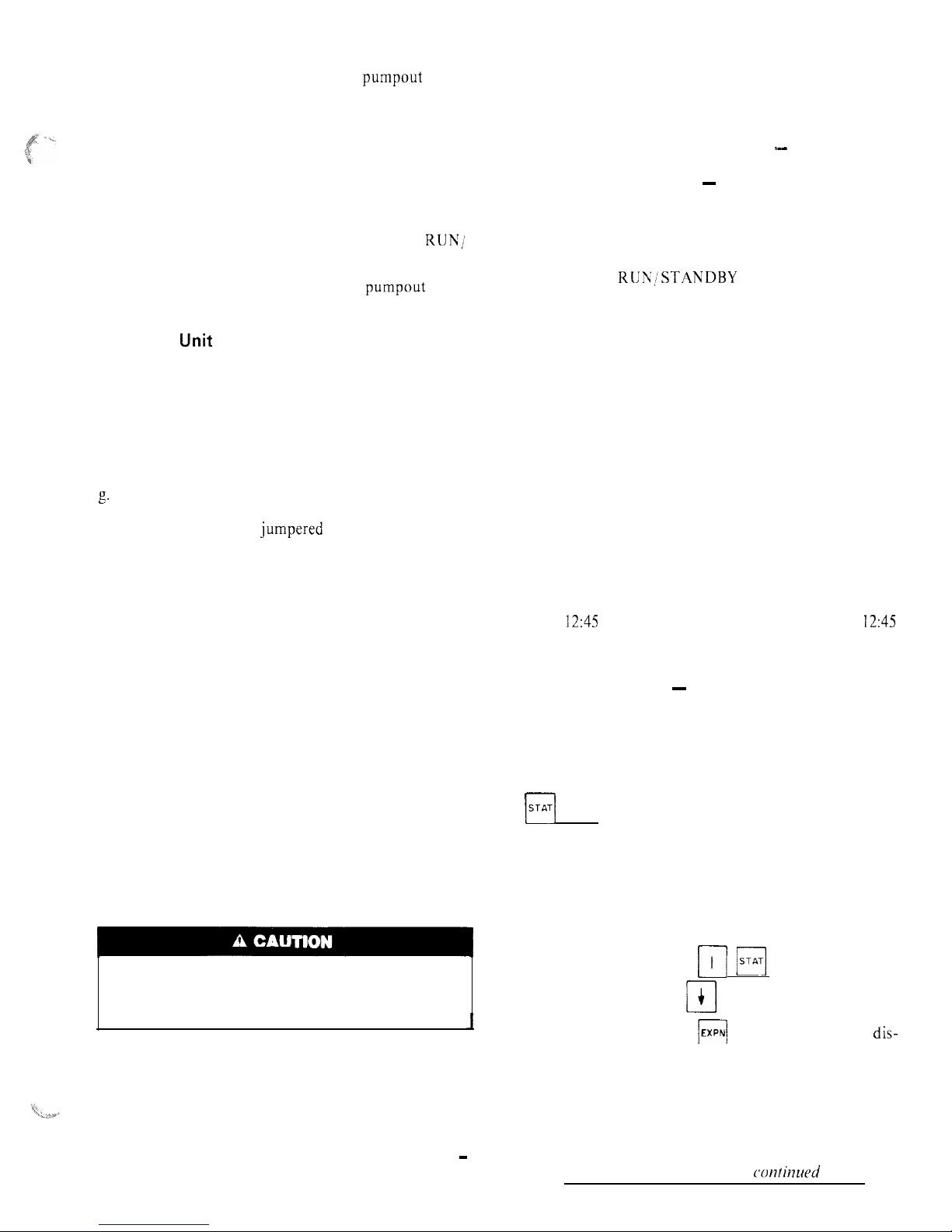
Up to 3 alarm codes can be stored at once. To view
them in sequence, press
m m
to enter the alarm
displays and then press key to move to the individ-
ual alarm displays. Press
I
EXPN)
after a code has been
dis-
played and the meaning of code will scroll across the
screen.
When a diagnostic (alarm) code is stored in the display
and the machine automatically resets, the code will be
deleted. Codes for safeties which do not automatically
reset will not be deleted until the problem is corrected
and the machine is switched to STANDBY, then back
to RUN.
confinued on page IO
5
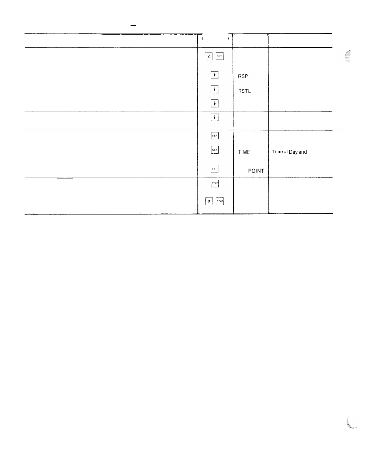
Table 5 - Accessing Functions and Subfunctions
OPERATION
To access a function, press the subfunction number and the
function name key. The display will show the subfunction group
To move to the other elements, scroll up or down using the arrow
keys
When the last element in a subfunction has been displayed, the first
element wilt be repeated
To move to the next subfunction, it is not necessary to use the
subfunction number; pressing the function name key will advance
the display through all subfunctions within a function and then back
to the first
To move to another function, either depress the function name key
for the desired function (display will show the first subfunction)
or
Access a particular subfunction by using the subfunction number
and the function name key
KEYBOARD
ENTRY
DISPLAY
RESET
RSTR
RSP
DEMAND
TtME
SET
POINT
X ALARMS
STAGES
DESCRIPTION
Reset Set Points
Reset Set Point
Reset Limit
Reset Ratio
Reset Set Point
Demand Limit Set Points
Timeof Dayand Day
of Week Display
System Set Points
X Alarms Detected
Capacity Stages
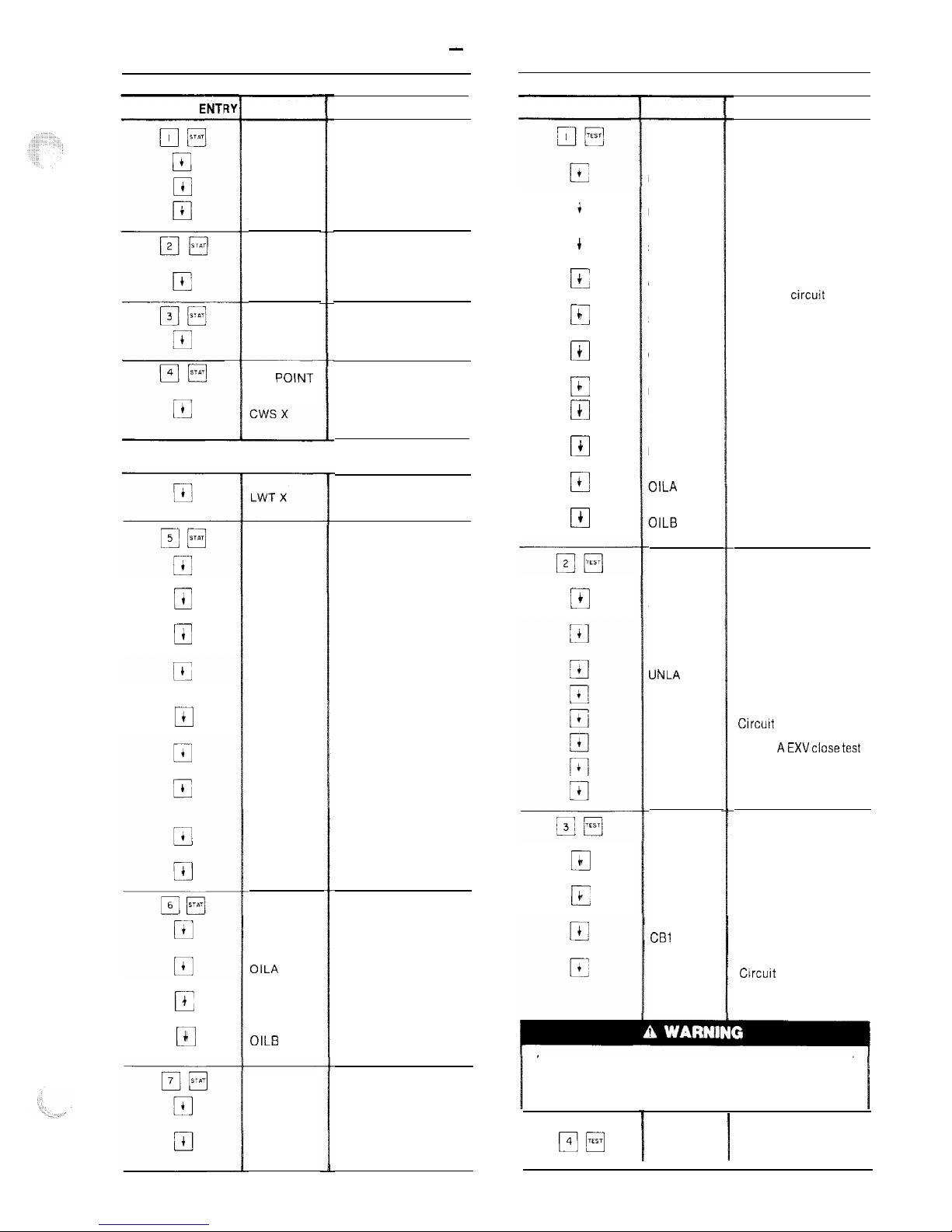
Table 6 - Keyboard Directory
STATUS
QUICK TEST
KEYBOARD ENTI DISPLAY KEYBOARD ENTRY
DISPLAY COMMENT
Factory/field test of
inputs
Leaving water
temperature
Entering water
temperature
Saturated suction temp
circuit A
Compressor suction
gas temp circuit A
Saturated suction temp
circuit B
Compressor suction
gas temp circuit B
Reset temperature
Loss of charge switch
circuit A
Loss of charge switch
circuit B
Oil pressure switch
circuit A
Oil pressure switch
Circuit B
Factory/field test of
outputs
Circuit A liquid line
solenoid test
Circuit B liquid line
solenoid test
Unloader A test
Unloader B test
Circurt A EXV open test
Circuit AEXVclosetest
Circuit B EXV open test
Circuit B EXV close test
Factory/field test of
compressors
Circuit A compressor 1
test
Circuit A compressor 2
test
Circuit B compressor 1
test
Circuit B compressor 2
test
COMMENT
Current alarm displays
Alarm 1
Alarm 2
Alarm 3
Current operating
mode displays
Mode 1
Capacity stages
Stage number
Current operating
set point
Leaving chilled water
set point
INPUTS
LWT X
EWT X
SSTA X
CGTA X
SSTB X
CGTB X
RST X
LCSA X
LCSB X
OILA X
OILB X
OUTPUTS
SLDA X
SLDB X
UNLA X
UNLB X
EXVAO X
EXVAC X
EXVBO X
EXVBC X
COMP
CA1 X
CA2 X
CBI X
CB2 X
X ALARMS
ALARM X
ALARM X
ALARM X
MODE
MODE X
STAG ES
X STAGE
q
4
El
+
r=
c
0
c
0
+
0
c
cl
4
ill
c
SET POlNT
If unit is in dual set point mode the set point currently in effect
is displayed. ’
0
t
El
4
Leaving water
temperature
System temperatures
Cooler leaving water
temp
Cooler entering water
temp
Saturated suction temp
circuit A
Compressor suction
gas temperature
circuit A
Superheat temp
circuit A
Saturated suction temp
circuit B
Compressor suction
gas temperature
circuit B
Superheat temp
circuit B
Reset temperature
Systems pressures
Circuit A loss of charge
switch
Circuit A oil pressure
switch
Circuit B loss of charge
switch
Circuit B oil pressure
switch
System analog values
Circuit A EXV valve
position
Circuit B EXV valve
position
TEMPS
LWT X
EWT X
SSTA X
CGTA X
SHA X
SSTB X
CGTB X
SHB X
RST X
PRESS
LCSA X
OILA X
LCSB X
OILB X
0
i
G
i
cl
4
17
4
0
4
c
4
c
+
Cl
$
During test of compressors, each compressor will start and
run for 10 seconds. Compressor servicevalves and the liquid
line valve must be open. Energize compressor crankcase
heaters for 24 hours prior to performing compressor tests.
ANALOG
EXVA X
EXVB X
p-Jm
END TEST
I
Leave quick test
7
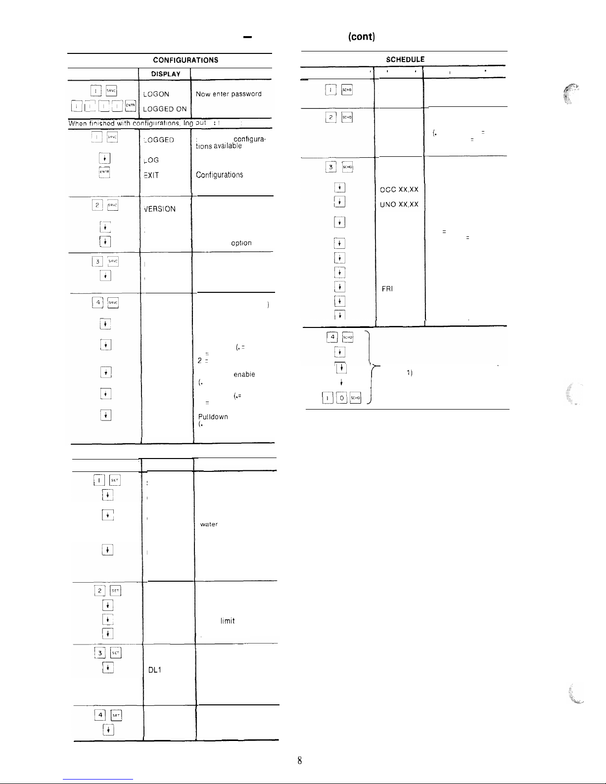
Table 6 - Keyboard Directory (cant)
SERVICE CONFIGURATtONS
KEYBOARD ENTRY
COMMENT
KEYBOARD ENTRY 1 DtSPLAY
i
COMMENT
DISPLAY
OVRD X
SCHTYP X
PERIOD 1
MON X
TUE X
WED X
THU X
FRI
X
SAT x
SUN X
Entering number of
hours to extend
Schedule Type
( ) = entry codes
(.
= inactive, 1 = single
set point, 2 = dual set
point)
3ut
as
follows.
-0GGED ON \
-0G OFF
KXIT
LOG /
Shows that confrgura-
tlons
avaIlable
Define time schedule
period 1
Start of occupied time
Return to unoccupied
time
Monday flag
( ) = entry codes
(1 = yes, . = no)
Conflgurations now
again password
protected
Software version
number
Software version
Language
optJon
tiERSION
xxx
xxx
Factory configuration
Number of unloaders
(enter number, or. for
zero)
Field configuration (
)
= entry codes
Number of unloaders
(enter number)
Reset type (. = none
’
1 = return water,
2 = space or outside air)
Load shed enable
(.
= disable, 1 = enable)
Ftuid type
(.=
water,
1 = brine)
Pulldown enable
(.
= disable, 1 = enable)
FACT CFG
COMP X
FFD CFG
UNLS X
RSTP X
LDSH X
FLD X
PLDN X
Sunday flag
LL
r
Time periods 2-8 (same elements as
period I)
q
4
SET POINT
COMMENTDISPLAY
SET POINT
cwso x
cwsu x
MSP X
RESET
RSP X
RSTL X
RSTR X
KEYBOARD ENTRY
System set points
Occupied chilled water
set point
E
Unoccupied chilled
water set point appears
only when unit is in
dual set point mode
Modified chilled water
set point (read only).
Set point determined
by reset function
Reset set points
Reset set point
Reset limit
Reset ratio
DEMAND
DLl X
DL2 X
Demand limit set points
Demand limit set
point
Demand limit set
point 2
q
TIME
DAY 00.00 Current setting
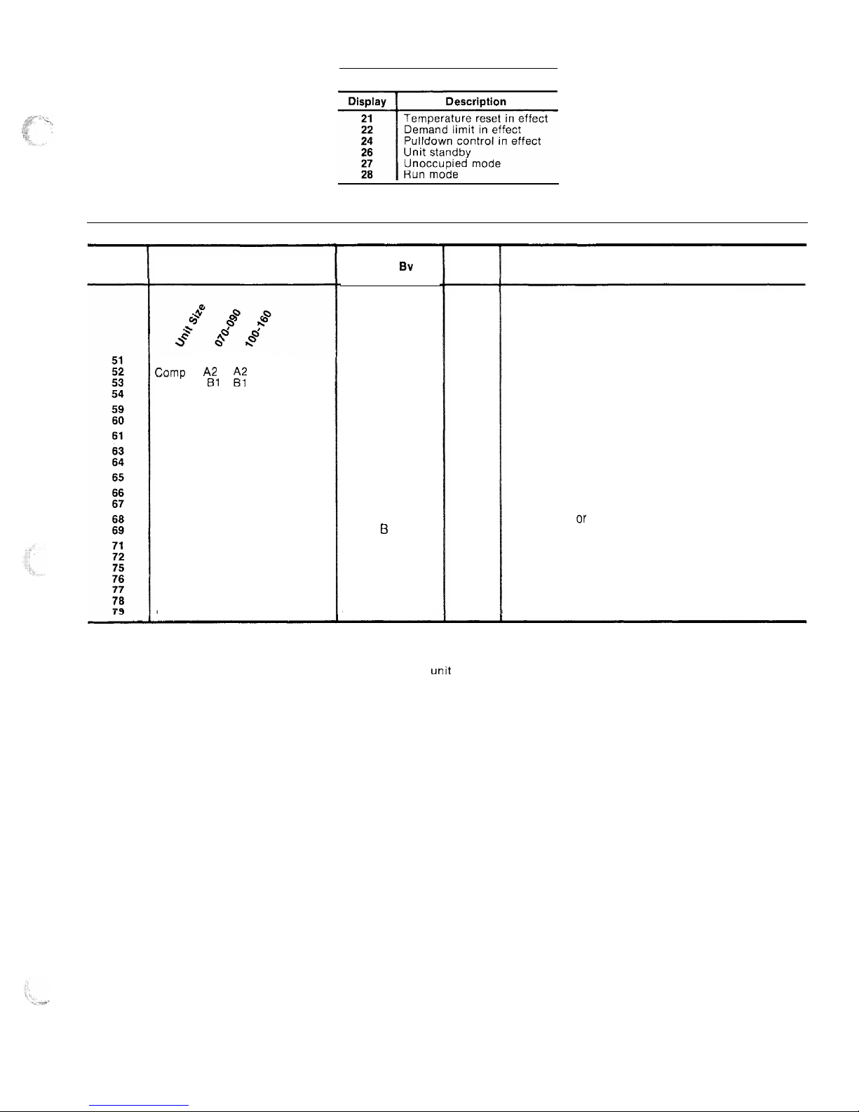
Table 7 - Display Codes
OPERATING MODES
Display
Description
Comp Al Al
Failure
Camp
A2
ii:
Failure
Comp Bl
Failure
Comp
B2 Failure
Loss of charge circuit A
Loss of charge circuit B
Low cooler flow
Low oil pressure circuit A
low oil pressure circuit B
Freeze protection
High suction superheat circuit A
High suction superheat circuit B
Low suction suoerheat circuit A
Low suction superheat circuit B
Leaving water thermistor failure
Entering water thermistor failure
Cooler thermistor failure circuit A
Cooler thermostor failure circuit B
Comp thermistor failure circuit A
Comp thermistor failure circuit B
Reset thermistor failure
ALARMS
Action
Taken
Sv
Control
Circuit A shut off
Comp shut off
Circuit B shut off
Comp shut off
Circuit A shut off
Circuit B shut off
Unit shut off
Circuit A shut off
Circuit B shut off
Unit shut off
Circuit A shut off
Circuit B shut off
Circuit A shut off
Circuit 6 shut off
Unit shut off
Use default value
Circuit A shut off
Circuit B shut off
Circuit A shut off
Circuit B shut off
Stop reset
Reset
Method
Manual
Manual
Manual
Manual
Manual
Manual
Manual
Manual
manual
Auto.
Manual
Manual
Manual
Manual
Auto.
Auto.
Auto.
Auto.
Auto.
Auto.
Auto.
Probable Cause
High pressure switch trip or high discharge gas temp
switch trip, on when it is not supposed to be on. Wiring
error between electronic control and compressor relay.
Low refrigerant charge, or loss of charge pressure switch
failure.
No cooler flow or reverse cooler flow
Oil pump failure or low oil level, or switch failure.
Low cooler flow
Low charge or EXV failure, or plugged filter drier.
EXV failure ar cooler thermistor error.
Thermistor failure, or wiring error, or thermistor not
connected to input terminals.
NOTES:
1. Freeze protection trips at 35 F (1.7 C) for water and 6 degrees F (3.3 degrees C) below set point
for brine units. Resets at 6 degrees above set point.
2. All auto. reset failures that cause the unit to stop will restart the
unit
when the error has been
corrected.
3. All manual reset errors must be reset by moving the control switch to STANDBY then to RUN.
4. Valid resistance range for thermistors is 363,000 ohms to 216 ohms.
9
 Loading...