

Page 1

INSTRUCTION HANDBOOK
APPLICARE
TARGA
CARATTERISTICHE
Page 2

- 2 -
READY US
READY US_EN - 2016/06 - Ed. 02
CARPIGIANI
Via Emilia, 45 - 40011 Anzola dell'Emilia (Bologna) - Italy
Tel. +39 051 6505111 - Fax +39 051 732178
This manual contains a TRANSLATION OF THE ORIGINAL INSTRUCTIONS and may not
be reproduced, transmitted, transcribed, led in a data retrieval system or translated into other
languages, without the prior written permission of CARPIGIANI.
The purchaser has the wright to reprint it for his own ofce use.
CARPIGIANI policy pursues a steady reasearch and development, thus it reserves the right to
make changes and revisions whenever deemed necessary and without being bound to previous
statements to the purchaser.
We wish to thank you for the preference granted to us by purchasing one of
Carpigiani machines.
To the best guarantee, since 1993 Carpigiani has submitted its own Quality System
to the certication according to the international Standard ISO 9001, nowadays
its production has got UNI-EN-ISO 9001:2008 Certied Quality System.
Issue: 02 Date: 2016/06 Changes: 3.
Issued by: AM Checked by: EZ Approved by: RL
Page 3

READY US
- 3 -
READY US_EN - 2016/06 - Ed. 02
TABLE OF CONTENTS
FOREWORD ....................................................................................................................... 5
INSTRUCTION MANUAL ...................................................................................... 5
PURPOSE ...................... ........................................................................................... 5
STRUCTURE OF THE MANUAL ........................................................................... 5
ADDITIONAL DOCUMENTATION ....................................................................... 5
CONVENTIONAL SYMBOLS ................................................................................ 6
QUALIFICATION OF THE PERSONNEL SYMBOLS .......................................... 6
SAFETY ............................................................................................................. 7
WARNINGS ............................................................................................................. 7
SEC. 1 GENERAL INFORMATION
1.1 GENERAL INFORMATION ................................................................................. 9
1.1.1 MANUFACTURER IDENTIFICATION DATA ............................................ 9
1.1.2 INFORMATION ABOUT MAINTENANCE SERVICE .............................. 9
1.1.3 INFORMATION FOR USERS ...................................................................... 9
1.2 INFORMATION ABOUT THE MACHINE ......................................................... 9
1.2.1 GENERAL INFORMATION ......................................................................... 9
1.2.2 TECHNICAL FEATURES ........................................................................... 10
1.3.3 MACHINE UNIT LOCATION .....................................................................11
1.3 INTENDED USE .....................................................................................................11
1.4 NOISE ......................................................................................................................11
1.5 MACHINE STORAGE ..........................................................................................11
1.6 DISPOSAL OF PACKAGING MATERIALS ......................................................11
1.7 WEEE (WASTE ELECTRICAL AND ELECTRONIC EQUIPMENT) .......... 12
SEC. 2 INSTALLATION
2.1 ROOM NECESSARY FOR MACHINE USE ..................................................... 13
2.2 WATER SUPPLY CONNECTION ....................................................................... 13
2.3 MACHINES WITH AIR-COOLED CONDENSER .......................................... 13
2.4 MACHINES WITH WATER-COOLED CONDENSER ................................... 14
2.4.1 WATER VALVE ADJUSTMENT ................................................................ 14
2.5 ELECTRIC CONNECTION ................................................................................ 14
2.5.1 REPLACING THE POWER CABLE .......................................................... 14
2.6 POSITIONING THE MACHINE ........................................................................ 15
2.7 TOP-UPS................................................................................................................. 15
2.8 MACHINE TESTING ........................................................................................... 15
SEC. 3 INSTRUCTIONS FOR USE
3.1 MACHINE SAFETY WARNINGS ...................................................................... 17
3.2 MACHINE CONFIGURATION .......................................................................... 17
3.3 CONTROLS ........................................................................................................... 18
3.3.1 ELECTRONIC CONTROL KEYBOARD .................................................. 18
3.4 GELATO PRODUCTION ................................................................................... 21
3.4.1 "GELATO" PRODUCTION ......................................................................... 21
3.4.2 "GELATO DF" PRODUCTION ................................................................... 22
3.4.3 "GELATO HOT" PRODUCTION ............................................................... 24
3.4.4 ICE CREAM DISPENSING ........................................................................ 25
3.4.5 USING THE ICE CREAM DISPENSING LEVER .................................... 25
3.4.6 SPIGOT DOOR CLOSING CAM ............................................................... 25
3.4.7 USING THE SHOWER AND THE SHOWER SUPPORT ......................... 25
3.5 USER PROGRAMMING ..................................................................................... 26
Page 4

- 4 -
READY US
READY US_EN - 2016/06 - Ed. 02
SEC. 4 SAFETY DEVICES
4.1 SPIGOT DOOR MICROSWITCH ...................................................................... 27
4.2 ALARMS ................................................................................................................ 27
4.2.1 BLACKOUT ................................................................................................ 28
SEC. 5 REMOVING, CLEANING AND REFITTING OF PARTS IN
CONTACT WITH THE PRODUCT
5.1 GENERAL INFORMATION ............................................................................... 29
5.2 WASHING CONDITIONS ................................................................................... 29
5.3 TIPS ......................................................................................................................... 29
5.4 HOW TO USE CLEANING/SANITIZING SOLUTION .................................. 30
5.5 EXTERIOR CLEANING ...................................................................................... 30
5.6 PRELIMINARY CLEANING .............................................................................. 30
5.7 BEATER REMOVAL ............................................................................................ 30
5.7.1 SCRAPER REMOVAL ................................................................................ 31
5.7.2 SEAL ........................................................................................................... 31
5.8 SPIGOT REMOVAL ............................................................................................. 32
5.8.1 ICE CREAM OUTFEED SPIGOT REMOVAL .......................................... 32
5.8.2 HOPPER COVER REMOVAL .................................................................... 32
5.8.3 ICE CREAM OUTFEED CHUTE REMOVAL .......................................... 33
5.9 SANITIZING ......................................................................................................... 33
5.10 HYGIENE ............................................................................................................... 33
SEC. 6 MAINTENANCE
6.1 SERVICE TYPE .................................................................................................... 35
6.2 WATER COOLING ............................................................................................... 36
6.3 AIR COOLING ...................................................................................................... 36
6.4 ORDERING SPARE PARTS ................................................................................ 36
6.5 SUPPLIED ACCESSORIES ................................................................................. 37
SEC. 7 TROUBLESHOOTING ............................................................................39
Page 5

READY US
- 5 -
READY US_EN - 2016/06 - Ed. 02
FOREWORD
INSTRUCTION HANDBOOK
Editing this handbook, it was taken into due account European Community directions on safety
standards as well as on free circulation of industrial products within E.C.
PURPOSE
This handbook was conceived taking machine users' needs into due account.
Topics relevant to a correct use of the machine have been analyzed in order to keep unchanged in
the long run quality features charachterizing CARPIGIANI machines all over the world.
A signicant part of this handbook refers to the conditions necessary to the machine use and to
the necessary procedure during cleanout as well as routine and special maintenance.
Nevertheless, this handbook cannot meet all demands in details. In case of doubts or missing
information, please apply to:
CARPIGIANI Via Emilia, 45 - 40011 Anzola dell'Emilia (Bologna) - Italy
Tel. +39 051 6505111 - Fax +39 051 732178
HANDBOOK STRUCTURE
This handbook is divided in sections, chapters and subchapters in order to be consulted more
easily.
Section
A section is the part of the handbook identifying a specic topic related to a machine part.
Chapter
A chapter is that part of a section describing an assembly or concept relevant to a machine part.
Subchapter
It is that part of a chapter detailing the specic component of a machine part.
It is necessary that each person involved in the machine operation reads and clearly understands
those parts of the handbook of his/her own concern, and particularly:
The Operator must read the chapters concerning the machine star-up and the operation of
machine components.
A skilled technician involved in the installation, maintenance, repair, etc., of the machine must
read all parts of this handbook.
ADDITIONAL DOCUMENTATION
Along with an instruction manual, each machine is supplied also with additional documentation:
Part list: A list of spare parts which is delivered together with the machine for its mainte-
nance.
Wiring diagram: A diagram of wiring connections is placed in the machine.
Before using the machine read carefully the instruction handbook.
Pay attention to the safety instructions.
Page 6
- 6 -
READY US
READY US_EN - 2016/06 - Ed. 02
CONVENTIONAL SYMBOLS
CAUTION: ELECTRIC SHOCK DANGER
The staff involved is warned that the non-obsevance of safety rules in carrying out the operation
described may cause an electric shock.
CAUTION DANGER FROM HIGH TEMPERATURES
This warns the staff involved that failure to abide by safety rules in carrying out the operation
described involves the risk of burns and scalds.
CAUTION CRUSHING HAZARD
This warns the staff involved that failure to abide by safety rules in carrying out the operation
described involves the risk of suffering crushed ngers or hands.
CAUTION: GENERAL HAZARD
The staff involved is warned that the operation described may cause injury if not performed following safety rules.
NOTE:
It points out signicant information for the staff involved.
WARNINGS
The staff involved is warned that the non-observance of warning may cause loss of data and
damage to the machine.
PROTECTIONS
This symbol on the side means that the operator must use personal protection against an implicit
risk of accident.
SYMBOLOGY QUALIFICATION OF THE STAFF
The staff allowed to operate the machine can be differentiated by the level of preparation and responsibility in:
MACHINE OPERATOR
Identify unqualied personnel, those without any specic technical abilities who are capable
of carrying out simple jobs, such as: operating the machine using the commands available on
the keypad, the loading and unloading of products used during production, the loading of any
consumable materials, basic maintenance operations, (cleaning, simple blockages, controls of
the instrumentation, etc.).
MAINTENANCE ENGINEER
He/she is a skilled engineer for the operation of the machine under normal conditions; he/she is
able to carry out interventions on mechanical parts and all adjustments, as well as maintenance
and repairs. He/she is qualied for interventions on electrical and refrigeration components.
CARPIGIANI ENGINEER
He/she is a skilled engineer the manufacturer assigned to eld interventions for complex jobs
under particular conditions or in accordance with agreements made with the machine's owner.
Page 7
READY US
- 7 -
READY US_EN - 2016/06 - Ed. 02
SAFETY
When using industrial equipment and plants, one must be aware of the fact that drive mechanisms
(rotary motion), high voltage components, as well as parts subject to high temperatures may cause
serious damage to persons and things.
Who is in charge of plant safety must be on the look-out that:
• an incorrect use or handling shall be avoided;
• safety devices must neither be removed nor tampered with;
• the machine shall be regularly serviced;
• only original spare parts are to be used especially as far as those components with safety
functions are concerned (ex.: protection microswitches, thermostats);
• suitable personal protective equipment is worn;
• high care must be payed during hot product cycling.
To achieve the above, the following is necessary:
• at the working place an instruction manual relevant to the machine should be available;
• tuch documentation must be carefully read and requirements must conse quently be met;
• only adequately skilled personnel should be assigned to electrical equipment;
IMPORTANT!
One must be on the look-out that the staff does not carry out any operation outside its own sphere
of knowledge and responsibility (refer to “Symbology qualication of the staff”)..
NOTE:
According to the standard at present in force, a SKILLED ENGINEER is who, thanks to:
- training, experience and education,
- knowledge of rules, prescriptions and interventions on accident prevention,
- knowledge of machine operating conditions,
is able to realize and avoid any danger and has also been allowed by the person in charge of
plant safety to carry out all kinds of interventions.
WARNING
When installing the machine, insert a differential magnetothermal protection switch on all poles
of the line, adequately sized to the absorption power shown on machine data plate and with
contact opening of 3 mm at least.
• Never put your hand into the machine, alike during production and cleaning operations. Before
carrying out any maintenance operation, make sure that the machine is in “STOP” position
and main switch has been cut out.
• It is forbidden to wash the machine by means of a bolt of water under pressure.
• It is forbidden to remove panels in order to reach the machine inside before having disconnected the machine.
•CARPIGIANI is not responsible for any accident that might happen during operation, clean-
ing and/or servicing of its units, if this warning has not been fully complied with.
Page 8

- 8 -
READY US
READY US_EN - 2016/06 - Ed. 02
Page 9

READY US
- 9 -
READY US_EN - 2016/06 - Ed. 02
1. GENERAL INFORMATION
1.1 GENERAL INFORMATION
1.1.1Manufacturer'sidenticationdata
The machine has a data plate carrying manufacturer data, machine type and serial number, assigned when it is manufactured.
Copy of machine data plate to be found on rst page of this handbook.
1.1.2 Information about service
All operations of routine maintenance are here described in section "Maintenance"; any additional
operation requiring technical intervention on the machine must be cleared with the manufacturer,
who will also examine the possibility of a factory technician eld intervention.
1.1.3 Information to the user
The manufacturer of the machine is at user's disposal for any explanation and information
about the machine operation.
In case of need, please call the local distributor, or the manufacturer, if no distributor is avail-
able.
Manufacturer's service department is available for any information about operation, and re-
quests of spare parts and service.
1.2 INFORMATION ABOUT THE MACHINE
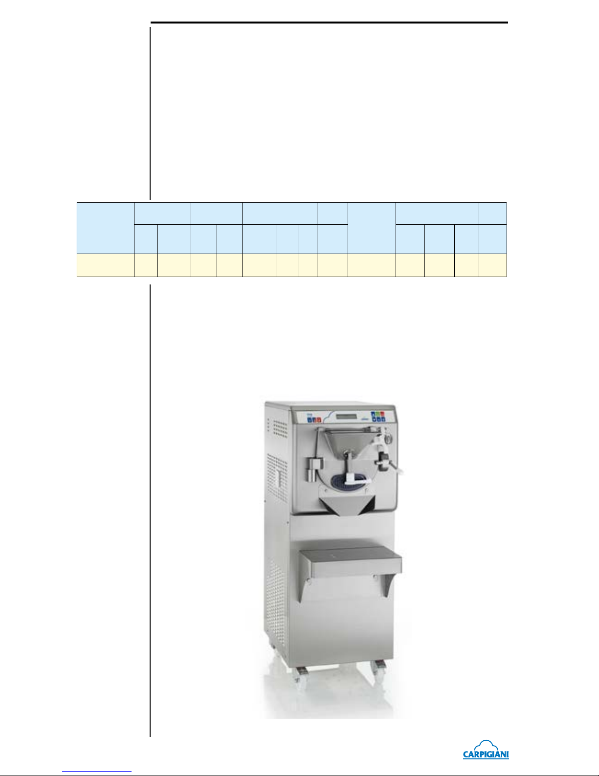
1.2.1 GENERAL DATA
The Ready models are ice cream producers that mix, heat and freeze the ice cream in one single
cylinder.
Page 10
- 10 -
READY US
READY US_EN - 2016/06 - Ed. 02
CARPIGIANI recommends to always use high quality mix for ice cream production in order
to satisfy your customers, even the hardest-to-please ones. Any saving made to the prejudice of
quality will surely turn into a loss much bigger than the saving itself.
Bearing in mind the above statements, please take heed of the following suggestions:
• Make your mixes yourselves from high quality natural ingredients or buy them from reliable
companies.
• Follow closely instructions given by your mix supplier for the preparation of the mixes.
• Do not alter your mix supplier's recipies, by adding, for instance, water or sugar.
• Taste ice cream before serving it and start selling it only if entirely satisfactory.
• Make sure your staff always keeps the machine clean.
Have your machine serviced always by companies authorized by CARPIGIANI.
1.2.2 Technical features
MODEL
Production
output
Mix q.ty per
batch
electric spec.*
Rated
Power
Condenser**
Dimensions
Net
weight
kglblitres
Qt
Min.
kg
lb
Max.
kglbVolt Hz Ph
kW
HP
Width
cm
in
Depth
cm
in
Height
cm
in
kg
lb
Ready 30 45 DF
30/45
60/99
42/60
38/54.4
3,5
7.7
7,5
16.5
208-230 60 3
5.2
6.9
Water
52
20.46525.5
14055290
639
The quantity per cycle and hourly production change according to the mixes used.
The values "Max" refer to the Italian classic easy-to-work ice-cream.
* Other voltages and cycles available with an extra cost.
** The air-cooled condenser is available with an extra charge.
The following characteristics are purely indicative, Carpigiani reserves the right to make all the changes whenever necessa
-
ry and without being bound to previous statements to the purchaser.
Page 11
READY US
- 11 -
READY US_EN - 2016/06 - Ed. 02
1.3 INTENDED USE
The Ready must only be used for the production of ice cream, with the respect of what indicated
in 1.2.1 "General information", within the limits indicated here under.
Voltage: ±10%
Min air temperature : 50°F
Max air temperature: 109°F
Min water temperature: 50°F
Max water temperature: 86°F
Min. water pressure: 0,1 MPa (1 bar/14.5 PSI)
Max water pressure: 0,8 MPa (8 bar/116 PSI)
Max relative humidity : 85%
This machine has been designed for its use in rooms not subject to explosion-proof laws; its use
is thus bound to complying rooms and normal atmosphere.
1.4 NOISE
The steady acoustic pressure level weighed A in a working place alike by watercooled and by
aircooled machines is less than 70 dB(A).
1.5 STORING A MACHINE
The machine must be stored in a dry and dump-free place.
Before storing the machine, wrap it in a cloth in order to protect it against dust and else.
1.6 DISPOSAL OF PACKING STUFFS
When opening the packing crate, separate packing stuffs per type and get rid of them according
to laws in force in machine installation country.
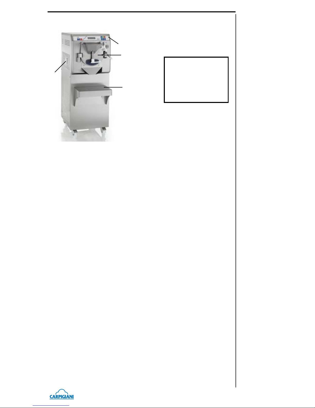
1.2.3 Location of machine groups
Caption:
1 Control panel
2 Cylinder front lid
3 Shelf for drip tray
4 Drip drawer
1
4
3
2
Page 12
- 12 -
READY US
READY US_EN - 2016/06 - Ed. 02
1.7 WEEE (Waste Electrical and Electronic Equipment)
In conformity with the European Directives 2006/66/EC, on batteries and accumulators and
waste batteries and accumulators, and 2002/96/EC, also known as WEEE, the presence of the
symbol on the side of the product or packaging means that the product must not be disposed of
with normal urban waste. Instead, it is the user’s responsibility to dispose of
this product by returning it to a collection point designated for the recycling
of electrical and electronic equipment waste. Separate collection of this waste
helps to optimize the recovery and recycling of any reclaimable materials and
also reduces the impact on human health and the environment.
For more information concerning the correct disposal of this product, please
contact your local authority or the retailer where this product was purchased.
Page 13

READY US
- 13 -
READY US_EN - 2016/06 - Ed. 02
2. INSTALLATION
2.1 ROOM NECESSARY TO THE MACHINE USE
The machine must be installed in such a way that air can freely circulate all around.
Rooms for the approach to the machine must be left free in order to enable the operator to act
without constraint and also to immediately leave working area, if need be.
The minimum approach room to working area should be at least 59 in. in consideration of space
taken by opened doors.
ATTENTION
Machines with air-cooled condenser must have 6 in. of free space along the sides in order
to allow free air circulation around the condenser.
NOTE
An insufcient air circulation affects operation and output capacity of the machine.
2.2 WATER SUPPLY CONNECTION
The machine must be connected to running water which pressure must not be higher than 0,8
MPa (8 bars/116PSI).
By aircooled machines, water connection for drinking water (for machine wash) is placed under
the machine.
By watercooled machines water connections (for machine wash and gas cooling) are placed on
upper panel.
ATTENTION
Theequipmentistobeinstalledwithadequatebackowprotectiontocomplywithap-
plicable federal, state, and local codes.
2.3 MACHINE WITH AIRCOOLED CONDENSER
Machines with air-cooled condenser must have 6 in. of free space along the sides in order to
allow free air circulation around the condenser.
NOTE
An insufcient air circulation affects operation and output capacity of the machine.
6 in
6 in
4 in
59 in
Water-cooled Version
6 in
6 in
59 in
Air-cooled Version
Page 14

- 14 -
READY US
READY US_EN - 2016/06 - Ed. 02
2.4 MACHINES WITH WATERCOOLED CONDENSER
To make the machine run, a watercooled machine must be connected to running water supply,
or to a cooling tower.
Water must have a pressure of 0.1 MPa and 0.8 MPa (1-8 bar / 14.5-116 PSI) at least, and a delivery at least equal to the estimated hourly consumption.
Connect inlet pipe marked by plate "Water Inlet" to water supply installing a shut-off valve, and
outlet pipe marked by plate "Water Outlet" to a drain pipe, installing a shut-off valve.
2.4.1 Water valve adjustment
IMPORTANT
If water valve needs be reset, this operation will have to be carried out by skilled personnel,
only.
Valve adjustment must be carried out in such a way that no water ows when machine is off and
lukewarm water ows when machine is on.
NOTE:
Water consumption increases if temperature of entering water is above 68°F.
ATTENTION:
Do not leave the machine in a room with temperature below 32°F
withoutrstdrainingwaterfromthecondenser.
2.5 ELECTRIC CONNECTION
Before connecting the machine to the mains, check that machine voltage indicated in data plate
corresponds with the mains.
Insert a differential magnetothermal protection switch adequately sized to absorption capacity
required and with contact opening of 3 mm at least.
The machines are delivered with a 5 wire cable: blue wire must be connected to the neutral
lead.
IMPORTANT
Yellow/green ground wire must be connected to an adeguate ground plate.
2.5.1 Replacing the power cable
Should the machine main cable be damaged, it must be replaced immediately through one with
similar features.
Replacement shall be carried out by skilled technicians, only.
IMPORTANT
Direction of rotation
Beater rotation is anticlockwise
Reversal of rotation
Should direction of rotation be wrong, reverse it by exchanging two of the three phases which
start at the differential magnetothermal protection switch.
Page 15

READY US
- 15 -
READY US_EN - 2016/06 - Ed. 02
2.6 LOCATION
The machine is provided with castors for an easy positioning; a mechanical block system, once
engaged, prevents machine from moving and keeps it standstill.
2.7 REFILLING
Motor installed in the machine is of the type with lubrication for life; no action of checking/replacing or topping up is necessary.
Gas lling necessary to the freezing system is carried out at CARPIGIANI works during machine
postproduction testing.
If a gas addition happens to be made, this must be carried out by skilled technicians, only, who
can also nd out trouble origin.
2.8 MACHINE TESTING
A postproduction test of the machine is carried out at CARPIGIANI premises; Operation and
output functionality of the machine are thoroughly tested.
Machine test at end user's must be carried out by skilled technicians or by one of CARPIGIANI
engineers.
After the machine positioning and correct connections, also carry out all operations necessary to
functional check and test of the machine.
Fig. 4
Page 16

- 16 -
READY US
READY US_EN - 2016/06 - Ed. 02
Page 17

READY US
- 17 -
READY US_EN - 2016/06 - Ed. 02
3. DIRECTIONS FOR USE
3.1 MACHINE SAFETY WARNINGS
When using industrial equipment and plants, one must be aware of the fact that drive mechanisms
(rotary motion), high voltage components, as well as parts subject to high temperatures may cause
serious damages to persons and things.
Who is in charge of plant safety must be on the look-out that:
an uncorrect use or handling is avoided;
safety devices must neither be removed nor tampered;
the machine is regularly serviced;
only original spare parts are to be used especially as far as those components with safety func-
tions are concerned (ex.: protection microswitches, thermostats);
suitable personal protective equipment is worn.
To achieve the above, the following is necessary:
At working place an instruction manual relevant to the machine should be available.
Such documentation must be carefully read and regulations must consequently be followed.
Only adequately skilled personnel will have to be assigned to electrical equipment.
3.2 MACHINE CONFIGURATION
The machine has a motor to drive the beater, and a cooling system with water or air-cooled condenser and a heating system.
Feed mix (ready-made liquid mix, mix to be re-hydrated and mix to be brought to 194°F) into the
cylinder and start the automatic production cycle, until ice cream reaches the ideal consistency
set by CARPIGIANI; use the minimum and maximum mix quantity per cooling cycle specied
in the chart under paragraph 1.2.2. When the cycle ends, the ice cream is ready to be extracted
through the spigot door and dispensed directly into a tub.
WARNING
In any case, do not touch the door during the heating stage or the stages immediately
after, since it can reach very high temperatures.
WARNING
To make product dispensing easier, only use the plastic spatula supplied. Never use metal
spatulas as these could damage the machine.
Ice cream
(end product)
Ice cream mix
Page 18

- 18 -
READY US
READY US_EN - 2016/06 - Ed. 02
3.3 CONTROLS
This machine is provided with an electronic control keyboard; every key relates to a machine
function. For a correct use of the keys, press on the symbol or in the middle of the key; every key
has a LED (light emitting diode) which lights up when relevant function is inserted.
3.3.1 Electronic control keyboard
STOP
In this function, the machine is not working and the relevant red LED is on. The display shows STOP. After 3 minutes, the display backlighting turns off and the display
turns on when pressing any key.
CLEANING
If Cleaning button is pressed, the display shows:
* CLEAN
HOT CLEAN
Use the Increase and Decrease keys to select the desired function and press OK to
activate it.
The available functions are:
- Clean
- Hot Clean
- Dry clean
Clean
In this function, only the slow beater is enabled for 1 minute, then the machine au-
tomatically sets back to STOP in order to avoid the excessive wear of cylinder and
beater; the display shows the decreasing timer on the top line and the speed on the
bottom line.
TIMER 01:00
SPEED 01
Press the Increase key to enable the quick beater. The timer continues its count:
TIMER 01:00
SPEED 02
It is possible to reset slow beating by pressing the Decrease key.
Hot clean
Beater with speed 1 (that can be changed from 1 to 2) and heating are enabled for 1’.
Dry clean
Heating is activated for 1'.
INCREASE
This increases the values that can be edited for those functions where this is permitted, e.g., to change the freezing timer.
Moreover, it allows changing the Beating speed in the Cleaning and Extraction functions.
Page 19

READY US
- 19 -
READY US_EN - 2016/06 - Ed. 02
DECREASE
This decreases the values that can be edited for those functions where this is permitted, e.g., to change the freezing timer.
It is also used to reset alarm messages.
Moreover, it allows changing the Beating speed in the Cleaning and Extraction functions.
OK
If pressed when viewing the menus, this starts up the selected cycle.
It is used during cycles to conrm that ingredients have been introduced or to conrm
the continuing of a process after the Stop button has been pressed. Skip to the next
phase by holding it down for a prolonged period during a pause (timer) or in the
heating phase.
WATER DELIVERY
It can be accessed from any function.
The relevant LED turns on, water delivery is activated for a xed time of 3’ or until
Stop or the Water Delivery Key are pressed.
Water Delivery Time Storage
If the Water Delivery Button is pressed for approx. 3" (until you hear a "beep") during
water delivery, this latter is stopped and the time elapsed since its activation is stored.
When the sprayer is used again, the delivery time will be the stored one.
To increase time, use user step U14.
GELATO PRODUCTION
By pressing the Gelato Production key the display shows:
* GELATO
GELATO FRUIT
Use the Increase and Decrease keys to move the asterisk selecting the required cycle.
The available cycles are:
- Gelato
- Gelato Fruit
- Slush Fruit
-
Cool. in Standby
Press OK to activate the selected cycle.
GELATO DF PRODUCTION
By pressing the Dry Filling Gelato Production key the display shows:
* GELATO DF
GEL FRUIT DF
Use the Increase and Decrease keys to move the asterisk selecting the required cycle.
The available cycles are:
- Gelato DF
- Gelato Fruit DF
- Gelato Milk
- Gelato HOT DF
- G Fruit HOTDF
- Gel Milk HOT
Press OK to activate the selected cycle.
Page 20

- 20 -
READY US
READY US_EN - 2016/06 - Ed. 02
GELATO HOT PRODUCTION
By pressing the Gelato HOT Production key the display shows:
* GELATO HOT
Press OK to activate the selected cycle.
In these cycles, when the temperature in the cylinder reaches 104°F, a "WARNING
HOT" message is displayed alternated with the set temperature.
SET 185 °F
MIX 108 °F
WARNING HOT
MIX 108 °F
EXTRACTION
The function can be accessed from Gelato and Fruit Gelato cycles only.
In this function the relevant LED turns on, only the slow beating motor is enabled
and the display shows a time countdown.
TIMER 03:00
Speed 1
Press STOP or wait 3' (xed) to stop beating.
From Extraction mode it is possible to access the Cooling extraction function by
pressing the Gelato Production key. In this case, the Production LED turns on for 20”
xed; at the end of such time the machine sets back to simple extraction unless the 3
total minutes of extraction have already passed; in this case the machine sets to STOP.
Press the Increase key to activate quick beating. To enable slow beating again press
the Decrease key.
Page 21

READY US
- 21 -
READY US_EN - 2016/06 - Ed. 02
3.4 GELATO PRODUCTION
After cleaning, sanitizing and completely rinsing the machine right before the use, according to
the instructions in sec. 5 Cleaning, make sure spigot door and ice cream outlet spigot door are
properly closed and proceed as follows:
3.4.1 "Gelato" production
Take the mix, pour the required quantity into the cylinder, through the hopper of spigot door
respecting the minimum and maximum quantities indicated in the table under paragraph 1.2.2.
By pressing the Gelato Production key the display shows:
* GELATO
GELATO FRUIT
Use the Increase and Decrease keys to move the asterisk selecting the required cycle.
The available cycles are:
- Gelato
- Fruit Gelato
- Fruit Slush
-
Cooling in Standby
Press OK to activate the selected cycle.
Gelato and Fruit Gelato (sherbet) Cycle
The product is cooled in the cylinder till its consistency value is reached. According to the selected
cycle, Gelato or Fruit Gelato, the proper Consistency Set is automatically set.
In case of Gelato cycle the display shows:
SET 100
GELATO 005
While in case of Fruit Gelato Cycle:
SET 060
GEL.FRU 005
SET = the consistency to reach (it can be changed using the Increase/Decrease keys)
GELATO and FRU GEL. = the current consistency
Consistency is displayed in real time.
Once the desired consistency is reached (also called Set HOT), the beater keeps running emitting
an intermittent sound in order to indicate that the ice cream is ready; from this moment on, the
SET cannot be changed.
Fruit Slush Cycle
The product is cooled in the cylinder till its consistency value is reached. The display shows:
SET 10:00
SLUSH 09:56
SET are the total freezing minutes. This time can be changed, during freezing, using the Increase
and Decrease keys in steps of 1 minute from a minimum of 2 to a maximum of 20 minutes.
SLUSH is the decreasing time.
The last minute of freezing will only be beating.
At the end of freezing an intermittent beep will be emitted.
Cooling in Standby
Press Ice Cream button
and scroll the menu using the Increase and Decrease buttons to move
the asterisk next to the required program:
FRUIT SlUSH
* COOL. IN STANDBY
conrm with OK.
This function allows storing ice cream residues inside the machine in case of production standby times.
Page 22

- 22 -
READY US
READY US_EN - 2016/06 - Ed. 02
3.4.2 "Gelato DF" production
By pressing the Dry Filling Gelato Production key, the display shows:
* GELATO DF
GEL FRUIT DF
Use the Increase and Decrease keys to move the asterisk selecting the required cycle.
The available cycles are:
- Gelato DF
- Gelato Fruit DF
- Gelato Milk
- Gelato HOT DF
- G Fruit HOTDF
- Gel Milk HOT
Press OK to activate the selected cycle.
Gelato DF Cycle
The display will read:
Set qt 00.00
OK ?
Use the Increase and Decrease keys to set the amount of water to deliver in number of liters.
Set qt 01.00
OK ?
Press OK to activate water dispensing. When the counter reaches half the set quantity, dispensing
stops and the display shows:
Solids?
Press OK to enable the beater and insert the solids (mix powder or paste).
Once the solids have been inserted, the display shows:
End Solidis?
Press OK to activate water delivery for the remaining half.
At the end of delivery, the machine sets to Beating, the Beating time can be changed pressing the
Increase/Decrease keys from 1 to 4’:
Beating
TIMER 02:59
The set time is stored.
At the end of beating, the machine will start the freezing cycle.
SET 100
GELATO 043
Fruit Gelato DF Cycle
The cycle is very similar to the Gelato DF cycle but using the Fruit Gelato cycle freezing parameters.
Milk Gelato Cycle
The cycle is very similar to the Gelato DF Cycle but displaying the following message:
1/2 Milk ?
both at cycle start and after inserting the solids.
Page 23

READY US
- 23 -
READY US_EN - 2016/06 - Ed. 02
Gelato HOT DF Cycle
The "HOT" cycles are used for hot processing.
WARNING
In any case, do not touch the door during the heating stage or the stages immediately
after, since it can reach very high temperatures.
The cycle is similar to Gelato DF cycle but at the beginning of the cycle the temperature is set:
SET 122 °F
OK ?
it can be changed using the Increase and Decrease keys, press OK to conrm. Then the display
shows the number of liters that can still be changed using the Increase and Decrease keys:
Set qt 00.40
OK ?
Press OK to activate water dispensing.
When the counter reaches half the set quantity, dispensing stops and the display shows.
Solids?
Press OK to enable beating and insert the solids (powders).
Once the solids have been inserted, the display shows:
End Solids?
Press OK to activate water delivery for the remaining half.
A 3' (+ heating) beating function is activated. The display shows:
Beating
TIMER 03:00
At the end of delivery (or by pressing OK), the machine sets to Heating:
SET 122 °F
MIX 050 °F
Once set is reached, the machine sets to Cooling until 39°F
SET 039 °F
MIX 124 °F
Once 39°F are reached, the machine starts the freezing cycle.
SET 100
GELATO 043
Gelato Fruit HOT DF Cycle
The cycle is very similar to the Gelato HOT Cycle with the Fruit parameters and hot processing.
WARNING
In any case, do not touch the door during the heating stage or the stages immediately
after, since it can reach very high temperatures.
Gelato Milk HOT Cycle
The cycle is very similar to the Milk Gelato Cycle with the hot processing.
WARNING
In any case, do not touch the door during the heating stage or the stages immediately
after, since it can reach very high temperatures.
Page 24

- 24 -
READY US
READY US_EN - 2016/06 - Ed. 02
3.4.3 "Gelato HOT" production
Pour the required quantity of mix into the cylinder, through the hopper of spigot door respecting
the minimum and maximum quantities indicated in the table under paragraph 1.2.2.
By pressing the Gelato HOT Production key the display shows:
* GELATO HOT
Press OK to activate the selected cycle.
Gelato HOT Cycle
Pasteurization cycle with the possibility to set the pasteurization set.
WARNING
In any case, do not touch the door during the heating stage or the stages immediately
after, since it can reach very high temperatures.
The control unit automatically counts the pause time (for example 185°F pause of 1', 149°F pause
of 30 minutes).
The display will read:
SET 185 °F
MIX 068 °F
On the top there is the temperature to reach and on the bottom the mix current temperature.
Once the heating set is reached, cooling activates and the display shows for example:
SET 039 °F
MIX 176 °F
Once 39°F are reached, the machine automatically sets to Gelato cycle and displays:
SET 100
GELATO 042
WARNING
User takes full responsibility for the manual control of pasteurization, complying with
prevailing local regulations on mix handling in case they are not pasteurized.
Page 25

READY US
- 25 -
READY US_EN - 2016/06 - Ed. 02
3.4.5 Using the ice cream dispensing lever
Locking
Lock ice cream outfeed by taking lever (ref. 1) fully down and rotating it fully to the right.
Opening
Turn lever (ref. 1) to the left by 90°.
Raise lever and spigot.
Lock spigot up by taking lever (ref. 1) fully home to the right.
Closing
Repeat the opening procedure in the reverse sequence to close.
3.4.6 Spigot door closing cam (ref. 2)
To open:
Push the knob towards the front and pull it to the right.
To close:
Close the spigot door, push the knob to the left and lower it.
3.4.4 Ice cream dispensing
At the end of the freezing cycle, the ice cream can be extracted from the cylinder as
follows:
Set tub on the support, under the ice cream outfeed chute.
Turn locking lever to the left (ref. 1).
Raise lever and spigot door.
Lock spigot door up by taking lever fully home to the right.
Select the EXTRACTION function (the speed can be changed using the Increase and
Decrease keys).
SAFETY REMARK
The machine sets to STOP after 3 minute of continuous operation in extraction mode in
order to avoid early wear of scrapers and cylinder
1
2
3.4.7 Using the shower and the shower support
Open the hopper cover, rotate the shower support (ref. 3) and lay it on the spigot door hopper
as shown in the gure. Remove the shower (ref. 4) from its seat and insert it in the suitable seat
of the shower support.
3
4
Page 26

- 26 -
READY US
READY US_EN - 2016/06 - Ed. 02
3.5 USER PROGRAMMING
To access user programming with the machine in STOP mode, press the STOP and DECREASE
keys at the same time; hold them until the display shows "Manager Menu" and the Software version.
Then the display shows the rst step of programming and the relevant value.
The values can be changed using the INCREASE and DECREASE keys.
Step Display Notes U.M. MIN MAX Typical
U01 Hours hr 0 23
U02 Minutes min 0 59
U03 Day of the week dd Sun Sat
U04 Day of the month dd 1 31
U05 Month mm 1 12
U06 Year yyyy 2000 2099
U07 Language
Ita, Eng, Fra,
Deu, Esp
Ita Esp
Ita
U08 Fahrenheit Y/N No Yes No
U09 Quart Y/N No Yes No
U14 Water Time Sec 015 300
180
U15 Timer BackLight Min 000 030
003
U01-U06: Date and time setting.
U07: Language setting
U08: Settings °C (No) / °F (Yes)
U09: Settings Liters (No) / Quart (Yes). 1 Quart = 1136 ml. The liter display is L whereas the
Quart display is qt.
U14: Setting of water delivery time from the shower.
U15: Setting of the minutes after which display backlighting turns off with machine set to Stop.
It can be turned back on by activating any function, in Programming or pressing OK. If this step
is set to 0, display backlighting is always on.
To exit user programming, wait for about 30 seconds without pressing any button or press
CLEANING/EXTRACTION to force quit.
Page 27

READY US
- 27 -
READY US_EN - 2016/06 - Ed. 02
4. SAFETY DEVICES
4.1 SPIGOT DOOR MICROSWITCH
On the closing spigot door of the cylinder, in which the beater unit is located, there is a microswitch
which immediately controls machine stop if the spigot door is opened.
WARNING
It is absolutely forbidden to tamper with or eliminate any devices in place to ensure ope-
rator's safety.
WARNING
CARPIGIANI can not be held liable for any loss or damage or injury to persons and/or
the machine, in case any safety-related devices are tampered with.
4.2 ALARMS
The machine signals possible alarms by displaying them on line two and ashing the message
on the display.
If an alarm was triggered and then reset, the alarm remains visible on the display in a steady way
(not ashing).
To delete the message after restoring the alarm, press the Decrease button. If the alarm will not
reset, this means it is still active.
Alarms are listed in the table below:
Alarm PR
Pressure switch
This alarm stops the compressor.
If pressure switch trips 3 times in a row or if it stays open for 2
consecutive minutes, the machine sets to Stop. The display reads
"Alarm PR".
Alarm RTC
Compressor Thermal Relay
When the Compressor thermal relay triggers, all outputs are disabled
and the machine sets to Stop. The display reads "Alarm RTC" until
the alarm is active.
Alarm RTL
Slow Beater Thermal Relay
When the Slow Beater thermal relay triggers, all outputs are disabled
and the machine sets to Stop. The display reads "Alarm RTL" until
the alarm is active.
Alarm RTV
Quick Beater Thermal Relay
When the Quick Beater thermal relay triggers, all outputs are
disabled and the machine sets to Stop. The display reads "Alarm
RTV" until the alarm is active.
Alarm TEC
"TEC" temperature probe switched off or short-circuited.
Alarm enabled in the heating cycles.
This alarm triggers machine Stop.
As long as alarm is active, none of the above-listed cycles can be
started.
Check TEC temperature probe and replace it if necessary.
Alarm TES
TES Safety thermostat
When the TES Safety Thermostat trips, the machine enters STOP
mode and the display reads “TES Alarm”.
Page 28

- 28 -
READY US
READY US_EN - 2016/06 - Ed. 02
Spigot Open
Magnetic Safety Switch (IMS) or Spigot Door Open
The machine sets to Stop from any function.
In Programming, the open spigot door is not signaled.
When the spigot door is closed again "Spigot Door Open" is no
longer displayed.
Power On
Power back on
After a blackout the display shows "Power back on".
If the machine needs an autodefrost, the alarm appears only for a
few seconds and then shows the Autodefrost display.
Timeout Product.
Timeout Production (Cooling fault)
It is triggered when the machine cooling is faulty. If compressor
remains on continuously for over 15', during freezing, and HOT
does not reach the threshold of the relevant cycle, the machine sets
to Stop with displayed "Timeout Prod." alarm. It can be reset by
pressing the Decrease key.
One of the possible causes for this type of problem could be no gas
in the system.
4.2.1 Blackout
In case of blackout, the machine will behave differently based on the function it was carrying
out upon blackout.
From the Stop, Clean, Extraction, Production and Dry Filling modes, the machine restarts in
Stop mode once the power returns.
From Heating and/or Pause cycle, the machine sets back to Heating and displays "Power back
on".
If, upon blackout, the machine was in ice-cream freezing cycle (once back to STOP mode) it will
enable (if necessary) the AUTODEFROST function which is cylinder defrost.
From the Cooling mode, the machine sets back to Cooling if the Time/Temp parameters go back
to the ones on the Blackout table and the display shows "Power back on".
From the Heating mode, the machine sets back to Heating if the Time/Temp parameters do NOT
go back to the ones on the Blackout table and the display shows "Power back on".
Blackout table
TEC Temperature Time
>122°F 30 minutes
120°F ÷ 59°F 10 minutes
59°F ÷ 50°F 20 minutes
48°F ÷ 39°F 2 hours
WARNING
If the blackout occurs during the heating stage and lasts for over 90 minutes, user takes the
responsibility for checking if the product in the machine is still suitable for consumption.
Page 29

READY US
- 29 -
READY US_EN - 2016/06 - Ed. 02
5. CLEANOUT DISASSEMBLING AND
REASSEMBLING OF PARTS IN CONTACT
WITH THE PRODUCT
5.1 GENERAL DESCRIPTION
Cleaning and sanitisation are operations that must be carried out habitually and with maximum
care at the end of each production run to guarantee the production quality and respect the necessary hygienic norms.
Giving dirt the time to dry out can greatly increase the risk of rings, marks and damage to surfaces. Removing dirt is much easier if it is done immediately after use because there is the risk
that some elements containing acid and saline substances can corrode the surfaces. A prolonged
soaking is recommended.
5.2 WASHING CONDITIONS
• Avoid using solvents, alcohol or detergents that could damage the component parts, the
machine or pollute the functional production parts.
• When manually washing never utilise powder or abrasive products, abrasive sponges or pointed
tools. There is a risk of dulling the surfaces, removing or deteriorating the protective lm that
is present on the surface and scoring the surface.
• Never use metal scouring pads or synthetic abrasives that could cause oxidization or make
the surfaces vulnerable to attack.
• Avoid using detergents that contain chlorine and its composites. The use of these detergents
such as bleach, ammonia, hydrochloric acid and decalciers can attack the composition of
the steel, marking and oxidising it irreparably and causing damage to the parts made from
thermoset materials.
• Do not use dishwashers and their detergent products.
5.3 SUGGESTIONS
• Use a non-aggressive detergent solution to wash the parts.
• Manually wash the parts in water (max 140°F) using a non-aggressive detergent and the clean-
ing brushes supplied as standard.
• Use drinking water (bacteriologically pure) to rinse the parts.
• To sanitise leave the disassembled parts in sanitised tepid water for 10-15 minutes (use the
sanitising product following the instructions of the manufacturer, the type and concentration
of sanitizing agent shall comply with 40 CFR §180.940 for example Kay-5 sanitizer) and rinse
them before reassembling.
• When the washing procedure has been completed and before the reassembly of each component dry thoroughly with a clean and soft cloth that is suitable for coming into contact with
foodstuffs, to avoid leaving any humidity rich in mineral salts and chlorine that could attack
the metal surfaces and leave opaque traces.
Carpigiani recommends the use of a cleaning/sanitising solution to wash the machine.
The use of a cleaning/sanitising solution optimises the washing and sanitising procedures in that
it eliminates two phases of the procedure (a rinse and a washing phase). In substance the use of a
cleaning/sanitising solution saves time by facilitating and simplifying washing/ sanitising procedures.
WARNING
Every time the machine is washed and its parts that come into contact with the ice cream
mix are disassembled it is essential to carry out a visual control of all the parts manufac-
tured in thermoset materials and metal such as sliding shoes, pump gears, beaters, etc.
All parts must be integral and not worn, without cracks or splits, or opaque if originally
polished/transparent.
Carpigiani declines all responsibility for any damage caused by imperfections and/or
undetected breakages and not promptly solved by the substitution of original spare parts
andisavailableforconsultationandforanyspecicrequestsmadebythecustomer.
Page 30

- 30 -
READY US
READY US_EN - 2016/06 - Ed. 02
5.5 OUTSIDE CLEANOUT
Clean the machine from dust and material its has been strewed with before shipment. Use water
only and add a mild detergent, such as soap and a smooth cloth.
5.6 PRELIMINARY CLEANOUT
With machine off and beater front lid closed, let water in the barrel.
Select the function CLEANOUT and let the beater run the least in order avoid a useless wear of
sliding shoes and cylidner.
Drain all water from the cylinder, open its lid so as to remove the beater.
5.7 BEATER DISASSEMBLY
Remove the agitator by pulling gently outwards.
Be careful not to damage the scraping palettes and
dent the cylinder walls with the agitator shaft.
WARNING
Carry out this operation with utmost care,
since beater may
be damaged in case it falls to the ground.
When reassembling the beater, catch it with both
hands and push the sliding shoes in order to insert
it easily. Push to the beater to the bottom and at the
same time let it turn in order to fully insert the beater
shaft into its seat.
5.4 HOW TO USE CLEANING/SANITISING SOLUTION
Prepare a solution of water and sanitising detergent following the instructions shown on the label
of the product being utilised.
Washing/sanitisation by immersion of components
- Manually remove the bulk residues utilising the supplied brushes.
- Remove ner residues with a jet of water.
- Immerse the parts to be cleaned into the solution.
- Let the solution react for the time indicated on the label of the product being utilised.
- Rinse the parts with care, using plenty of clean drinking water.
• Fully disassemble the sliding shoes.
• Withdraw the stufng box from its seat on the beater shaft.
• Wash all parts with cleaning/sanitizing solution, then rinse.
• Reassemble all parts previously disassembled, minding to grease the stufng box with a lm
of edible fat.
Beater
Sliding shoes
Stufng box
Fig. 11
Page 31

READY US
- 31 -
READY US_EN - 2016/06 - Ed. 02
5.7.2Stufngbox
On disassembling beater also check wholeness of stufng box; depending on machine operation
length, it is necessary to replace it through the spare one to be found in the accessory kit inside
machine packing.
• Remove beater assembly
• Remove stufng box from its seat
• Lubricate spare stufng box
• Mount the new stufng box
• Clean and lubricate the old stufng box and put it away for recovery of its elasticity.
IMPORTANT
Stufng box must be replaced with an original spare part each time ice cream drops are found on
withdrawing drip drawer placed at the machine side.
Keeping on operating the machine after nding ice cream drops brings about a bigger leakage
from stufng box, thence a malfunctioning of the machine which consequently affects production.
CAUTION
When you do not use the machine, leave beater lid open in order to avoid stufng box buckling.
5.7.1 Sliding shoes disassembly
Sliding shoes mounted on beater are "self-adjusting". An accurate cleaning secures full working
order of the system.
Fig. 12
Page 32

- 32 -
READY US
READY US_EN - 2016/06 - Ed. 02
5.8 SPIGOT DOOR REMOVAL
• Lift the lever (pos. 289) locking the
spigot door and move it to the right.
• Open spigot door pivoting on the
hinge (pos. 362).
• Lift spigot door to remove.
• Remove all mobile parts, including
the cylinder seal.
• Wash all removed parts using water
and cleaning/sanitizing solution and
rinse.
• Reinstall all removed parts taking care
to smear with some food-grade lubricant all O-rings and spigot door support shaft pos. 362.
5.8.1 Ice cream outfeed spigot removal
• Lift the spigot door (pos. 501) rotating the lever (pos. 502) by 90° on the left.
• Lift lever and spigot door and lock spigot door up by turning lever fully home to the right.
• Now remove the bottom O-ring (pos. 1126) from spigot door pivot and remove it, in this way
lever is released as well.
• Remove the O-ring (pos. 304) the spigot.
• Wash all removed parts using water and cleaning/sanitizing solution and rinse.
• Reinstall all removed parts taking care to smear all O-rings with some food-grade lubricant.
5.8.2 Hopper cover removal
To clean mix feeding area, with machine stopped, slide out cover retaining shaft (pos. 006) and
remove it.
Cover features a small bafe preventing ice cream from going up the hopper, which must be
removed and cleaned.
Wash all removed parts using water and
cleaning/sanitizing solution and rinse.
WARNING
During assembly of the hopper
cover, mount carefully the cover
retaining shaft (pos. 6), if mounted
in the absence of the dispenser
water support (pos. 930), its length
may damage the panel front of the
machine
290
350
006
007
304
501
291
1126
502
930
502
289
362
Page 33

READY US
- 33 -
READY US_EN - 2016/06 - Ed. 02
5.9 SANITIZATION
Operation required before each production process.
With the machine switched off and the beater lid closed, pour the detergent/sanitising solution
into the whipping cylinder.
Press the "CLEAN" button and start the "CLEAN" programme. Let the machine run for
10/15 seconds.
WARNING
Prolonged operation on the "CLEAN" setting with the cylinder empty or containing
water/sanitising solution will cause the beater sliding shoes to wear quickly.
Let the detergent/sanitising solution react in the cylinder for the time indicated on the label
of the product being utilised.
Fully drain the detergent/sanitising solution from the whipping cylinder.
Rinse utilising abundant clean water.
ATTENTION
Do not touch the sanitized parts with the hands, cloths or anything else.
WARNING
Before starting again with the ice cream production, rinse thoroughly with water
so as to remove any residues of the sanitizing solution.
5.10 HYGIENE
Ice cream fat contents are ideal elds for proliferation of mildew and bacteria.
To eliminate them, parts in contact with mix and ice cream must be thoroughly washed and
cleaned.
Stainless steel materials as well as plastic and rubber ones used for the construction of these parts
and their particular design make cleaning easy, but cannot prevent the growth of mildew and
bacteria if not properly cleaned.
5.8.3 Product chute removal
In order to make easier the removal of any ice-cream residue, remove the ice-cream chute using
both hands and turn it anti-clockwise so as to release it from its seat.
Wash the disassembled pieces with water and cleaning/sanitizing solution and then rinse
Page 34

- 34 -
READY US
READY US_EN - 2016/06 - Ed. 02
Page 35

READY US
- 35 -
READY US_EN - 2016/06 - Ed. 02
6. MAINTENANCE
CAUTION
Never put your hands into the machine, either during the operation or during cleaning.
Before servicing, make sure the machine has been set in "STOP" position and the main
switch has been cut out.
6.1 SERVICING TYPOLOGY
ATTENTION
Any servicing operation requiring the opening of machine panels must be
carried out with machine set to stop and disconnected from main switch!
Cleaning and lubricatingmoving parts is forbidden!
“Repairs to the wiring, mechanical, air supply or cooling systems, or to parts of same
mustbecarriedoutbyqualiedpersonnelwithpermissiontodosoandifnecessary,
according to the routine and extraordinary maintenance schedules as envisaged by the
customerwithreferencetospecicinterventionmethods,accordingtotheuseforwhich
the machine is destined”.
WARNING
Never use abrasive sponges to clean machine and its parts, as it might scratch their surfaces.
Operations necessary to proper machine running are such that most of servicing is completed during production cycle. Servicing operations, such as cleaning of parts in contact with the product,
replacing of stufng box, disassembling of beater assembly are to be carried out at the end of a
working day, so as to speed up serving operations required.
Herebelow you can nd a list of routine servicing operations:
-Cleanoutandreplacementofstufngbox
Cleaning should be carried out at the end of a working day, whilst replacement only after check-
ing of stufng box and in the event product drips inside drip drawer.
- Cleanout of beater
At the end of a working day
- Cleaning the metal sheets and drip tray
To be carried out daily with neutral soap , seeing to it that cleaning solution never reaches beater
assembly at its inside.
- Cleanout and sanitization
At the end of each working day, according to procedures described in section 5 of this manual.
- Sprayer maintenance
If there is a water leak from the sprayer, we advice you to replace the seals (ref. 1, 2, and 3) in case
they are broken, see the drawing. In order to replace the seals (ref. 1 and 2) it is enough to undo the
front white plug. On the other hand, to replace the seal (ref. 3) it is necessary to undo the front white
plug and remove the handle pin (ref. 4).
Page 36

- 36 -
READY US
READY US_EN - 2016/06 - Ed. 02
6.2 WATERCOOLING
By machines with watercooled condenser, water must be drained from condenser at the end of
selling season in order to avoid troubles in the event that the machine is stored in rooms where
temperature may fall under 32°F. After closing water inlet pipe, withdraw drain pipe from its seat
and let water ow out from circuit.
6.3 AIRCOOLING
Clean condenser, periodically, so as to remove dust, paper and what can prevent air from circulating. For cleanout, use a brush with long bristles or a bolt of compressed air.
ATTENTION
When using compressed air, put on personal protections in order to avoid accidents;
put on protective glasses!
Note:
nevere use sharp metal objects to carry out this operation. Good working of a freezing plant
mostly depends on cleaning of condenser.
6.4 ORDERING SPARE PARTS
When one or more parts are worn out or broken, place the order through your local distributor.
Page 37

READY US
- 37 -
READY US_EN - 2016/06 - Ed. 02
6.5 ACCESSORIES KIT
475
772A
028
304
830
291
840
072
Fig. 15
Description Position number
Beater stufng box 28
O-ring extractor 72
Lid gasket 291
Door seal 304
Accessories case 475
Brush 772A
Food-grade lubricant tube 830
Ice cream spatula 840
Page 38

- 38 -
READY US
READY US_EN - 2016/06 - Ed. 02
Page 39

READY US
- 39 -
READY US_EN - 2016/06 - Ed. 02
7. TROUBLESHOOT GUIDE
IRREGULARITY CAUSE PROCEDURE
Machine does not start Machine unplugged. Check and plug in.
Front lid is not closed well. Check front lid closure.
Compressor starts and Watercooled machine: Open water tap.
then stops after a few water does not circulate.
seconds without ice cream
being thick Check that hose is neither
squashed nor doubled up.
Aircooled machine: Check that rear ofmachine is
air does not circulate at least 19,6 in from wall.
Clean condenser from
obstructions.
After 30 minutes processing No gas. Check leakage and weld.
mix has not frozen and the
machine returns to Stop Pressure switch has broken Check connection
down. and replace, if need be.
Mix in drip drawer Stufng box missing Install if missing.
or ruined. Replace if ruined.
Ice cream comes out Gasket missing or not Check and x or replace.
from behind front lid properly installed.
 Loading...