


P.O. Box 4069 ∙ Winston-Salem, NC 27115 ∙ 336-661-9893 ∙ 336-661-9895 (Fax)
KW-77
Counter Model
Whipped Topping Dispenser
OPERATION MANUAL
Foreword
Thank you for selecting Coldelite to meet your operation and growing demands. Your Coldelite freezer has been manufactured utilizing the most advanced technology and modern equipment available in the industry. We at Coldelite, take great pride and care in the manufacturing of each and every freezer, using only the finest components available, to provide you with many years of trouble free operation.
Many years of experience in the manufacturing of soft serve dispensing equipment have guided us in the preparation of this Operation Manual. PLEASE READ IT CAREFULLY and keep it in an available place for future reference and most of all, follow the instructions carefully.
On the following pages, you will find important information and procedures, which describe the proper installation, sanitizing, operation, and maintenance of your Coldelite freezer. We feel certain that your compliance with these instructions will assure excellent performance, trouble-free operation and profitable business for years to come.
All technical data, pictures and drawings contained in this operation manual are not binding on the manufacturer, nor can the manufacturer be held liable for any modification to the freezer in part or completely.
Part Number:
2
Index |
|
Page # |
Foreword |
|
|
Part I |
Installation |
|
|
A) Uncrating |
4 |
|
B) Positioning the Machine |
4 |
|
C) Electrical Requirements |
5 |
Part II |
Explanation of Controls |
|
|
A) Electronic Control Panel |
5-6 |
|
B) Mix Injection Pump |
7 |
|
C) Texturizer and Dispensing Head |
7 |
Part III |
Initial Cleaning Procedure |
8 |
Part IV |
Assembling the Dispenser |
|
|
A) Assembling the Mix Injection Pump |
9 |
|
B) Assembling the Texturizer and Dispensing Head |
10 |
|
C) Assembling the Front Drip Cup |
11 |
Part V |
Sanitizing the Dispenser |
11 |
Part VI |
Starting the Dispenser |
12 |
Part VII |
Operating the Dispenser |
12 |
Part VIII |
Periodic Cleaning Procedures |
13 |
Part IX |
Technical Information |
|
|
A) Refrigeration |
13 |
|
B) Pump Drive Motor |
13 |
Part X |
Maintenance |
|
|
A) Troubleshooting Guide |
14-15 |
3
!! IMPORTANT !!
Failure to closely follow operational and maintenance procedures may result in damage to the unit and / or void your warranty. Coldelite Corporation will not be responsible for any machine not properly operated or maintained.
Part I – Installation
Before starting this procedure, ensure that the shipping carton does not show any evidence of damage due to dropping or mishandling. This may indicate that the dispenser was damaged during transit or delivery.
!! IMPORTANT !!
Should the outside of the shipping carton give any indication of possible damage, state this on the bill of lading prior to signing. Contact the freight carrier and request an inspection of damage. If this procedure is not adhered to, you will forfeit your rights to file a damage claim and be responsible for subsequent repair costs.
A) Uncrating the Dispenser
1)The outer shipping carton is secured to the shipping pallet with strapping. When cutting this strapping, do so with caution as it may spring out quickly. After cutting the strapping, lift the shipping carton straight up and off of the freezer.
2)Remove the protective foam boards and plastic wrapping from the outside of the freezer.
3)Unwind the power supply cord and inspect for any damage that may have occurred during transportation. If the cord is damaged or cut in any way, contact an Authorized Service Agent before connecting to a power source.
B) Positioning the Machine
After removing the machine from the shipping pallet, it is now ready to be located in its final location. Prior to choosing a location keep in mind that the dispenser should be accessible for periodic maintenance and have adequate space for necessary airflow. Please allow 6 inches of clearance on both sides of the dispenser.
The dispenser must also be level to ensure proper drainage from the mix tank. To level, place a level on all corners and shim as needed.
To seal the dispenser to the counter, proceed as follows:
Determine the exact location you would like to install the dispenser. Clean the counter top thoroughly of any dust, dirt or oil.
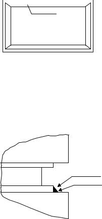
Apply a thin bead (1/4”) of General Electric RTV-102 (or equivalent) silicone sealant to the lower mounting rim of the dispenser. (Refer to Figure 1) 
Mounting Rim
Machine Bottom
Figure 1
Carefully lift the machine and place on the counter in the exact predetermined location. Remove any excess sealant from the base and counter to create a flawless seam between the counter top and machine base (Refer to Figure 2)
Machine |
Silicone Sealant
Machine Base |
Counter Surface |
Counter |
Figure 2
4
Allow the sealant to dry thoroughly before
operating the dispenser. Please refer to the sealant
manufacturer specs on the sealant tube.
THE MACHINE IS INTENDED FOR
INDOOR USE
C) Electrical Requirements
!!! WARNING !!!
This machine must be properly grounded. Failure to provide adequate grounding can result in severe electrical shock and / or fatal bodily injury.
This machine is provided with a power cord connected to the unit. You should have already inspected the cord for any damages that may have occurred during shipping. If there is no damage to the cord, you may plug it into the electrical receptacle.
For this dispenser, you will need to provide a dedicated electrical circuit with a rating of 115vac / 60hz / 1phase – 15amperes. This receptacle should be no farther than 6 feet from the dispenser and at no times should an extension cord be used. This electrical circuit must comply with your local and / or state regulations.
Part II – Explanation of the Controls
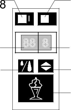
A) Front Touch Pad / CPU Unit
The model KW-77 machine is equipped with a central CPU unit. This unit contains the front touch pad, which monitors and controls the functions of the machine. The front touch pad is also the switching mechanism which operates the following:
*Refrigeration of the product *Activates the pump for dispensing *Set the mix tank storage temperature
*Set the portion size or continuous dispense mode
*Calibrate the temperature sensing probe *Displays mix tank temperature
Also contained in the CPU unit is a delay timer for the compressor. This delay will not allow the compressor to immediately start, but delay the start for three minutes. This delay will allow the internal refrigerant pressures to equalize, which will minimize high starting loads on the compressor.
571.1 |
571.2 |
ON |
OFF |
0 |
+ |
|
t |
570.1 |
|
570.2 |
°F |
sec. |
|
571.4 |
|
571.5 |
|
|
571.3 |
Front Switch Pad
5
 Loading...