

Carnes VCDK130I Installation Manual
MODELS
VCDK090
I
• VCDK130I• VCDK170
I
CARNES COMPANY, 448 S. Main St., P.O. Box 930040, VERONA, WI 53593-0040 • Phone: 608.845.6411 • Fax: 608.845.6470 • www.carnes.com • carnes@carnes.com
Form 11216-A
Page 1
IN-LINE
VENTILATORS • 120V
READ AND SAVE THESE INSTRUCTIONS
WARNING
CAUTION
TABLE OF CONTENTS
TO REDUCE THE RISK OF FIRE, ELECTRICAL SHOCK, OR
INJURY TO PERSONS, OBSERVE THE FOLLOWING:
1.
2.
3.
4.
5.
6.
7.
8.
9.
10.
Use this unit only in the manner intended by the manufacturer. If you have questions, contact the manufacturer at the
address or telephone number listed.
Before servicing or cleaning unit, switch power off at service
panel and lock the service disconnecting means to prevent
power from being switched on accidentally. When the service disconnecting means cannot be locked, securely fasten
a prominent warning device, such as a tag, to the service
panel.
Installation work and electrical wiring must be done by a
qualified person(s) in accordance with all applicable codes
and standards, including fire-rated construction codes and
standards.
Sufficient air is needed for proper combustion and exhausting of gases through the flue (chimney) of fuel burning
equipment to prevent backdrafting. Follow the heating
equipment manufacturer’s guidelines and safety standards
such as those published by the American Society for
Heating, Refrigeration and Air Conditioning Engineers
(ASHRAE), and the local code authorities.
When cutting or drilling into wall or ceiling, do not damage
electrical wiring and other hidden utilities.
Ducted fans must always be vented to the outdoors.
To reduce the risk of fire, use only metal ductwork.
If this unit is to be installed over a tub or shower, it must be
marked as appropriate for the application and be connected
to a GFCI (Ground Fault Interrupter) - protected branch circuit.
Never place a switch where it can be reached from a tub or
shower.
This unit must be grounded.
1.
2.
3.
For general ventilating use only. Do not use to exhaust hazardous or explosive materials and vapors.
To avoid motor bearing damage and noisy and/or unbalanced impellers, keep drywall spray, construction dust, etc.
off power unit.
Please read specification label on product for further information and requirements.
•
•
•
•
•
“TYPICAL INSTALLATION”
This sections shows a common installation in new and
existing, frame construction.
-Mounting (new construction)
-Mounting (existing construction)
-Wiring
-Ducting (straight-through blower discharge)
“DUCTING OPTIONS”
-Blower Discharge Positions
-Ducting (right-angle blower discharge)
“USE AND CARE”
“WARRANTY”
“SERVICE PARTS”
This manual is divided into sections as follows:
FORM 11216-A, Page 1
MODELS
VCDK090
I
• VCDK130I• VCDK170
I
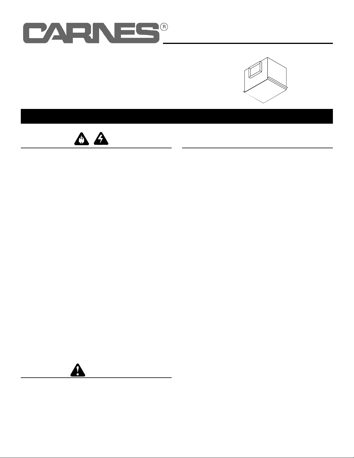
TYPICAL INSTALLATION
MOUNTING
(New Frame Construction)
12” ROUND DUCT
(OUTLET)
Ventilator
Factory-Shipped
In Straight-Through
Discharge Position.
9-3/8” x 12-3/4” TO
12” ROUND TRANSITIONS
MOUNTING
BRACKETS
CEILING
JOIST
(24” Centers
Shown)
Factory-shipped unit installed in new
construction.
12” ROUND DUCT
(Inlet)
12” ROUND DUCT
(Outlet)
Ventilator Factory-Shipped
In Straight-Through
Discharge Position.
9-3/8” x 12-3/4” TO
12” ROUND
TRANSITIONS
MOUNTING
SCREWS
CEILING
JOIST
(24” Centers
Shown)
Factory-shipped unit installed in existing construction.
MOUNTING
(Existing Frame Construction)
FINISHED
CEILING
MATERIAL
IMPORTANT:
Remove shipping tape from damper.
Remove the shipping tape from the damper flap and make sure
that damper flap opens and closes freely inside the ductwork.
Use duct tape to make ductwork connections secure and air-tight.
2
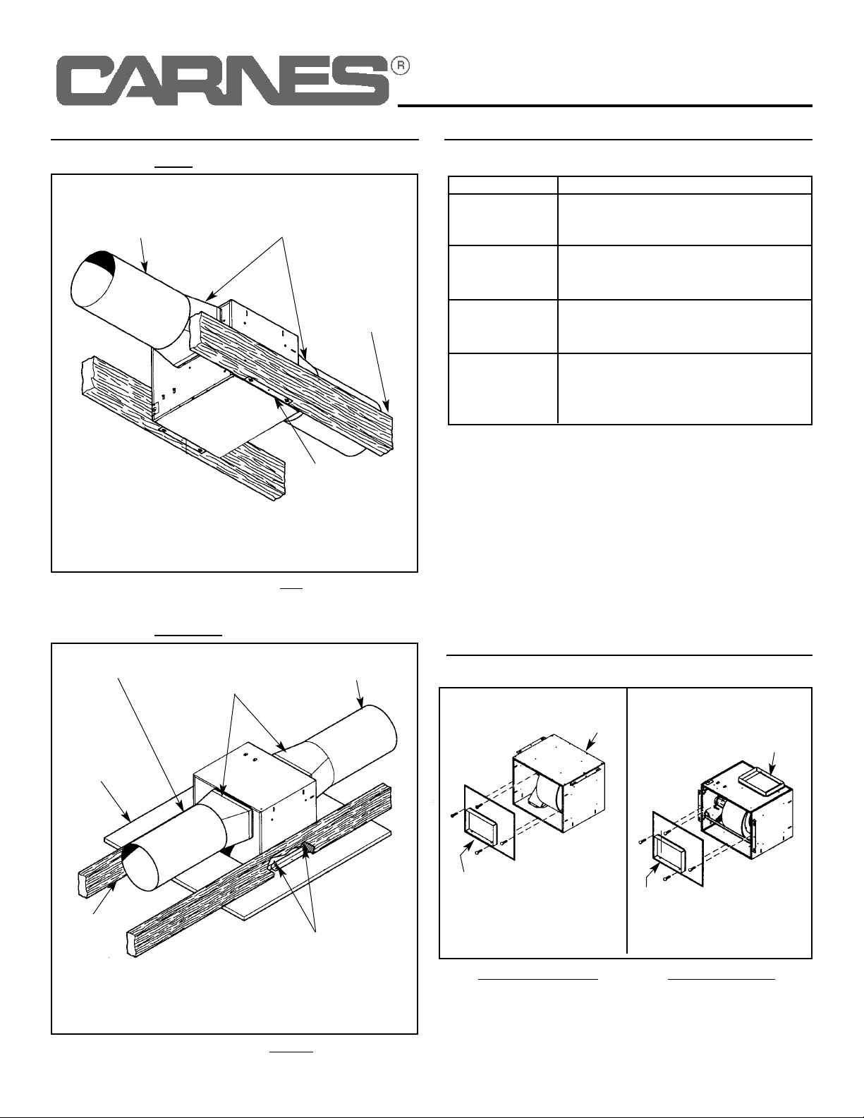
DUCTING OPTIONS
BLOWER DISCHARGE POSITIONS
Horizontal discharge
position. (Factory shipped)
V
ertical discharge
position.
DUCT CONNECTOR
(Outlet)
DUCT
CONNECTOR
(Outlet)
DUCT
CONNECTOR
(Intake)
DUCT
CONNECTOR
(Intake)
Housing
Disassembled
& Rotated To Be
Assembled With
Opening As
Shown
TYPICAL INSTALLATION
WIRING - 115V, 60 Hz., 1 Phase
Use U.L. approved connectors to wire per local codes. Connect
ground wire to bottom of conduit box.
UNIT SIZE WIRE CONNECTION
YELLOW TO L1, ORANGE TO L2
SEPARATE BROWN AND INSULATE
SEPARATE BLUE AND INSULATE
YELLOW TO L1, BROWN TO L2
SEPARATE ORANGE AND INSULATE
SEPARATE BLUE AND INSULATE
YELLOW TO L1, BLUE TO L2
SEPARATE ORANGE AND INSULATE
SEPARATE BROWN AND INSULATE
INSTALL INLINE BETWEEN L2
AND ORANGE, BROWN OR BLUE
CORRESPONDING TO UNIT
SIZE
170
130
090
Speed
Control
 Loading...