

Page 1
CEILING/WALL-MOUNT
VENTILATORS
READ AND SAVE THESE INSTRUCTIONS
MODELS
VCDD040C • VCDD050C • VCDD070C
®
Page 1
Page 1
WARNING
TO REDUCE THE RISK OF FIRE, ELECTRIC SHOCK, OR INJURY TO PERSONS, OBSERVE THE FOLLOWING:
1.Use this unit only in the manner intended by the manufacturer. If
you have questions, contact the manufacturer at the address or
telephone number listed in the warranty.
2.Before servicing or cleaning unit, switch power off at service panel
and lock the service disconnecting means to prevent power from
being switched on accidentally. When the service disconnecting
means cannot be locked, securely fasten a prominent warning
device, such as a tag, to the service panel.
3.Installation work and electrical wiring must be done by a qualified person(s) in accordance with all applicable codes and standards, including fire-rated construction codes and standards.
4.Sufficient air is needed for proper combustion and exhausting of
gases through the flue (chimney) of fuel burning equipment to
prevent backdrafting. Follow the heating equipment
manufacturer’s guideline and safety standards such as those
published by the National Fire Protection Association (NFPA),
and the American Society for Heating, Refrigeration and Air Conditioning Engineers (ASHRAE), and the local code authorities.
5.When cutting or drilling into wall or ceiling, do not damage electrical wiring and other hidden utilities.
6.Ducted fans must always be vented to the outdoors.
7.To reduce the risk of fire, use only metal ductwork.
8.If this unit is to be installed over a tub or shower, it must be
marked as appropriate for the application and be connected to a
GFCI (Ground Fault Interrupter) - protected branch circuit.
9.Never place a switch where it can be reached from a tub or
shower.
10. This unit must be grounded.
TABLE OF CONTENTS
This manual is divided into sections as follows:
•“TYPICAL INSTALLATION”
This section shows a common installation in new and existing,
frame construction.
- Mounting (new construction)
- Mounting (existing construction)
- Wiring
- Ducting (horizontal blower discharge)
•“MOUNTING OPTIONS”
•“WIRING OPTIONS”
-Wiring Plate Position
•“DUCTING OPTIONS”
- Blower Discharge Positions
- Ducting (vertical blower discharge)
•“USE AND CARE”
•“SERVICE PARTS”
•“WARRANTY”
CAUTION
1.For general ventilating use only. Do not use to exhaust hazardous or explosive materials and vapors.
2.To avoid motor bearing damage and noisy and/or unbalanced
impellers, keep drywall spray, construction dust, etc. off power
unit.
3.Please read specification label on product for further information and requirements.
!
Page 2
MODELS
VCDD040C • VCDD050C • VCDD070C
®
Page 2
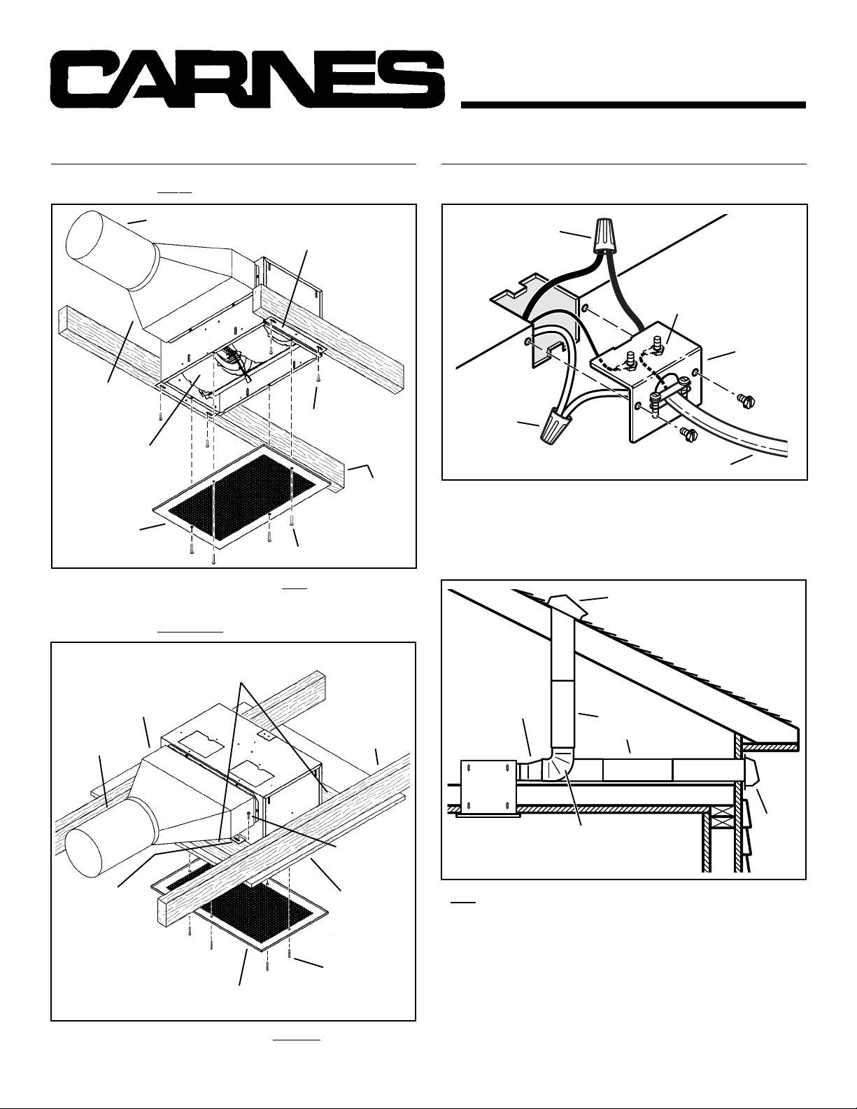
TYPICAL INSTALLATION
MOUNTING
4½” X 18½”
TO 10” ROUND
TRANSITION
Blower factory-shipped
in horizontal
discharge position.
GRILLE
Install after ceiling is
finished.
Factory-shipped unit installed in new construction.
(New Frame Construction)
10” ROUND DUCT
Mounting brackets
factory-shipped in
position for ½”
ceiling material.
MOUNTING
SCREW
GRILLE SCREW
CEILING
JOIST
(24” centers
shown)
TYPICAL INSTALLATION
WIRING
BLACK
TO
BLACK
GROUND TO
WIRING PLATE
WHITE
TO
WHITE
120 VAC LINE IN
Ventilator can be wired from outside of housing.
Use UL approved connectors to wir e per local codes.
DUCTING
(Horizontal blower discharge)
ROOF CAP
TOP / BACK
OF HOUSING
WIRING
PLATE
MOUNTING
4½” X 18½”
TO 10” ROUND
TRANSITION
10” ROUND
DUCT
MOUNTING
BRACKETS
(Attached to
opposite sides
of housing &
upside-down,
so housing is
flush with
finished ceiling)
(Existing Frame Construction)
2 X 4 FRAMING
(wide side down)
CEILING JOIST
(24” centers
shown)
MOUNTING
SCREW
FINSHED
CEILING
MATERIAL
GRILLE
SCREW
GRILLE
4½” X 18½”
TO 10” R OUND
TRANSITION
10”
ROUND
ELBOW
10”
ROUND
DUCT
WALL
CAP
Two ways to connect ductwork to a factory-shipped unit.
NOTE: Make sure the shipping tape is removed from the damper
flap and that damper flap opens and closes freely inside the
ductwork. Use duct tape to mak e ductwork connections secure and
air-tight.
Factory-shipped unit installed in existing construction.
Page 3
MODELS
VCDD040C • VCDD050C • VCDD070C
®
Page 3
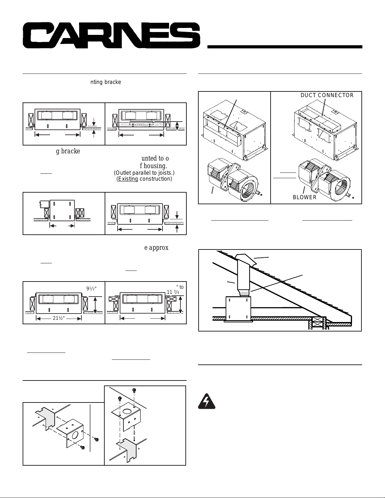
MOUNTING OPTIONS
¼-20 hex nuts secure mounting brackets to housing. Loosen and
re-tighten or remove and replace nuts as necessary for desired
mounting bracket position.
10
11
1½"
2½"
1
2
3
/
to
1
/
2
"
to
1
/
2
"
4
" to
3
/
4
"
1
/
1
MAX.
21½"
Mounting brackets in
factory-shipped position.
(Outlet parallel to joists.)
New construction)
(
12¼"
Mounting brackets mounted
to outlet sides of housing.
(Outlet perpendicular to joists.)
(
New construction)
1
9
/
2
" to
1
/
10
8"
21½"
Mounting brackets flipped
over and mounted to outlet
sides of housing.
(Outlet parallel to joists.)
(
Existing construction)
21½"
Mounting brackets flipped
over to give approx. 1”
more clearance.
(Outlet parallel to joists.)
(
New construction)
2
"
DUCTING OPTIONS
BLOWER DISCHARGE POSITIONS
DUCT CONNECTOR
BLOWER
Blower and duct connector
in
horizontal discharge
position. (Factory shipped)
DUCTING
10”
ROUND
DUCT
(Vertical blower dischar ge)
Change
blower
& duct
connector
positions
for vertical
discharge.
ROOF CAP
DUCT CONNECTOR
BLOWER
Blower and duct connector
in
vertical discharge
position.
4½” X 18½”
TO 10” ROUND
TRANSITION
21½"
Mounting brackets mounted
to top of sides of housing.
(Outlet parallel to joists.)
(
New or existing construction)
Mounting brackets flipped
over and mounted to top of
sides of housing.
(Outlet parallel to joists.)
(
New or existing construction)
WIRING OPTIONS
WIRING PLATE
POSITION
HORIZONTAL POWER
CABLE CONNECTION
Wiring plate mounts to side or top of housing.
21½"
VERTICAL
POWER
CABLE
CONNECTION
Typical ductwork connection to a ventilator converted to
vertical discharge.
USE AND CARE
V entilator is designed for continuous operation. If desired, it ma y be
controlled using an on/off switch or a solid-state, variable speed
control. Follow wiring instructions packed with control, and adhere
to all local and state codes, and the National Electrical Code.
WARNING: To reduce the risk of electric shock,
disconnect from power supply before servicing.
To clean grille: Use appropriate vacuum attachment or remove
grille and clean with a soft cloth and mild soap or detergent. Dry
grille thoroughly before reinstalling.
To clean blower assembly: Remove grille, unplug blower from
housing, remove blow er mounting nuts, and carefully remove b lower
from housing. Use appropriate vacuum attachment or a soft cloth
and mild soap or detergent to clean blower discharge area and
wheel. DO NOT ALLOW WATER TO ENTER MOTOR. Make sure
blower assembly is completely dry before reinstalling.
Motor is permanently lubricated. Do not oil or disassemble motor.
Page 4
VCDD040C • VCDD050C • VCDD070C
®
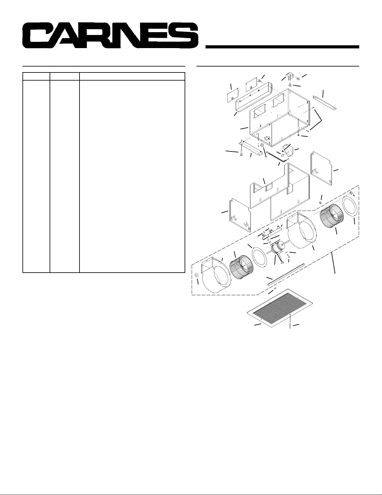
SERVICE PARTS SERVICE PARTS
KEY NO. PART NO. DESCRIPTION
1 97014744 Housing Assembly
2 97014728 Mounting Bracket (2 req.)
3 98009449 Duct Connector
4 97014822 Damper Flap Assembly (2 req.)
5 99150415 Screw, 8-18 x ¼ (18 req.)*
6 98005512 Wiring Plate
7 99150471 Ground Screw, 10-32 x ½ (2 req.)
8 98005513 Wire Box Cover
9 99400035 Strain Relief Bushing
10 97006039 Wire Harness
11 99500392 Wrapper Insulation
12 99500391 Side Insulation (2 req.)
13 99420466 Insulation Mounting Clip (6 req.)
14 99260477 Nut, ¼-20 (12 req.)*
15 97014745 Scroll Assembly (2 req.)
16 99110805 Blower Wheel (2 req.)
17 98009399 Inlet Ring (2 req.)
18 99080486 Motor (VCDD040C)
99080487 Motor (VCDD050C)
99080488 Motor (VCDD070C)
19 97014794 Motor Mounting Bracket
20 99100497 Rubber Isolator (4 req.)
21 99160380 Screw, 10-24 x 7/8 (4 req.)*
22 99250399 Washer (4 req.)*
23 99260306 Nut, Hex 10-24 (4 req.)*
24 99250254 Washer (4 req.)*
25 93260456 Nut, Hex Flange 3/8-16
26 98009461 Scroll Mounting Channel
--- ------------- Blower Assembly, Complete
(Includes Key Nos. 5 & 14-26)
97014817 (VCDD040C)
97014819 (VCDD050C)
97014821 (VCDD070C)
27 98009463 Grille
28 99420470 Grille Nut (4 req.)
29 99150472 Grille Mounting Screw (4 req.)
30 99150591 Screw, 10-16 x 7/8 (4 req.)
Order replacement parts by PART NO. - not by KEY NO.
* Standard hardware - may be purchased locally.
4
3
1
30
12
17
16
15
14
5
6
9
2
14
10
11
19
23
24
25
18
26
14
20
21
MODELS
Page 4
5
7
5
8
22
2
13
28
12
14
5
17
16
15
BLOWER
ASSEMBLY
CARNES
448 S. MAIN STREET
VERONA, WISCONSIN 53593
27
29
11236
 Loading...