

Page 1
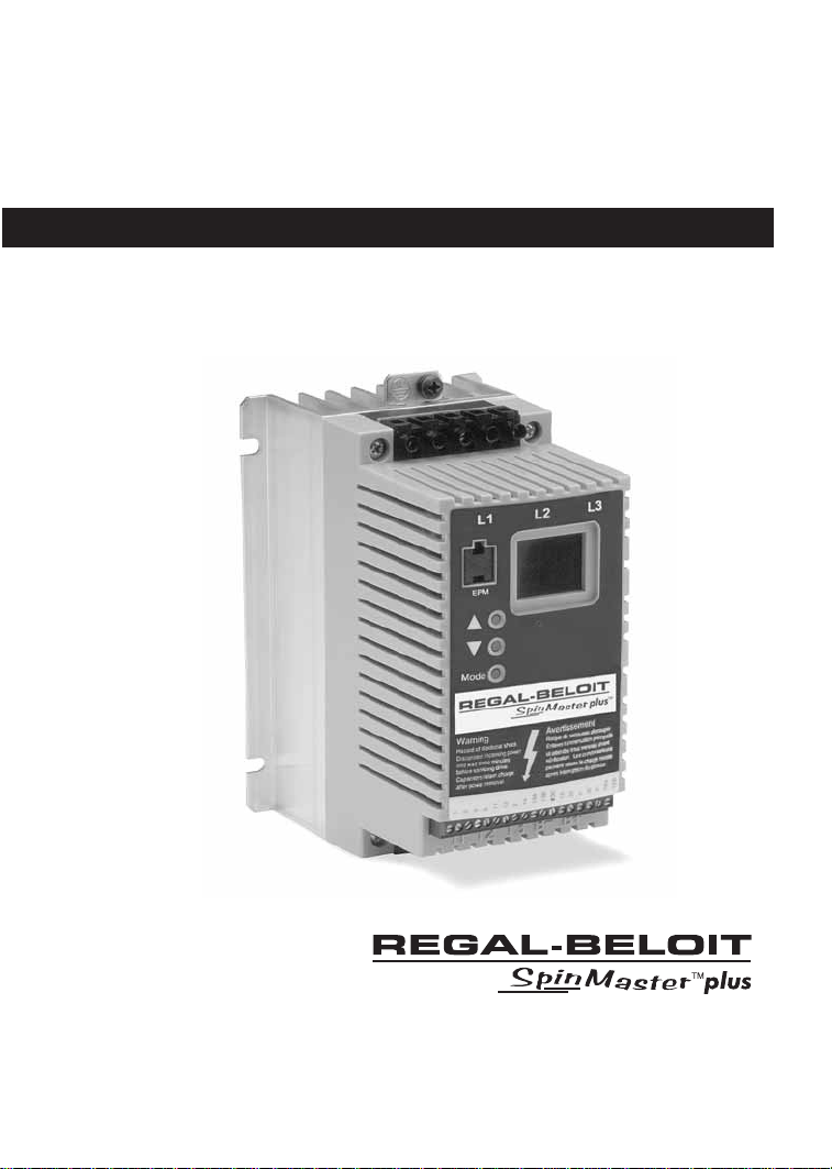
REGAL-BELOIT
Variable Speed AC Motor Drives
Installation and Operation Manual
Page 2

Manual Number: SB183, 12/04
TABLE OF CONTENTS
1.0 GENERAL . . . . . . . . . . . . . . . . . . . . . . . . . . . . . . . . . . . . . . . . .1
2.0 SpinMaster™ Plus DIMENSIONS . . . . . . . . . . . . . . . . . . . . . . . .2
4.0 SpinMaster™ Plus SPECIFICATIONS . . . . . . . . . . . . . . . . . . . . . .4
5.0 SpinMaster™ Plus RATINGS . . . . . . . . . . . . . . . . . . . . . . . . . . . .5
6.0 INSTALLATION . . . . . . . . . . . . . . . . . . . . . . . . . . . . . . . . . . . . .7
7.0 INPUT AC POWER REQUIREMENTS . . . . . . . . . . . . . . . . . . . . . .8
8.0 POWER WIRING . . . . . . . . . . . . . . . . . . . . . . . . . . . . . . . . . . .11
9.0 SpinMaster™ Plus POWER WIRING DIAGRAM . . . . . . . . . . . . .13
10.0 CONTROL WIRING . . . . . . . . . . . . . . . . . . . . . . . . . . . . . . . . .14
11.0 SpinMaster™ Plus CONTROL WIRING DIAGRAMS . . . . . . . . . .17
12.0 INITIAL POWER UP AND MOTOR ROTATION . . . . . . . . . . . . . .22
13.0 PROGRAMMING THE SpinMaster™ Plus DRIVE . . . . . . . . . . . .24
14.0 PARAMETER MENU . . . . . . . . . . . . . . . . . . . . . . . . . . . . . . . . .28
15.0 DESCRIPTION OF PARAMETERS . . . . . . . . . . . . . . . . . . . . . . . .31
16.0 TROUBLESHOOTING . . . . . . . . . . . . . . . . . . . . . . . . . . . . . . .47
17.0 SpinMaster™ Plus DISPLAY MESSAGES . . . . . . . . . . . . . . . . . .49
APPENDIX B – PI SETPOINT CONTROL OPTION . . . . . . . . . . .51
Page 3

IMPORTANT NOTICE
The following , and information is supplied to you for
your protection and to provide you with many years of tr ouble free and safe operation of your
Marathon Electric product.
• Hazard of electrical shock! Capacitors retain charge after power is removed. Disconnect
incoming power and wait until the voltage between terminals B+ and B- is 0 VDC before
servicing the drive.
• Hazard of electrical shock! Wait three minutes after disconnecting incoming power
before servicing drive. Capacitors retain charge after power is removed.
• Automatic starting of equipment may cause damage to equipment and / or injury to
personnel! Automatic start should only be used on equipment that is inaccessible to personnel.
• DRIVES MUST NOT BE INSTALLED WHERE SUBJECTED TO ADVERSE ENVIRONMENTAL
CONDITIONS SUCH AS: COMBUSTIBLE, OILY, OR HAZARDOUS VAPORS OR DUST;
EXCESSIVE MOISTURE OR DIRT; VIBRATION; EXCESSIVE AMBIENT TEMPERATURES. CONSULT REGAL-BELOIT CORPORATION FOR MORE INFORMATION ON THE SUITABILITY OF
A DRIVE TO A PARTICULAR ENVIRONMENT.
• Severe damage to the drive can result if it is operated after a long period of storage or
inactivity without reforming the DC bus capacitors!
• Do not connect incoming AC power to output terminals T1, T2, or T3. Severe damage
to the drive will result.
• When operating in JOG mode, the STOP terminal (TB-1) and the STOP key (on the
optional remote keypad) WILL NOT
stop the drive. To stop the drive, remove the JOG
command.
• When operating in JOG mode, the STOP terminal (TB-1), the AUXILIARY STOP function
(see setting 08), and the STOP key on the optional remote keypad WILL NOT stop the
drive. To stop the drive, remove the JOG command.
• JOG REVERSE will operate the drive in reverse rotation even if ROTATION DIRECTION
(Parameter 17) is set to FORWARD ONLY.
• DO NOT connect incoming AC power to output terminals T1, T2, and T3! Severe damage to the drive will result. Do not continuously cycle input power to the drive more
than once every two minutes. Damage to the drive will result.
• Do not remove the EPM while power is applied to the drive. Damage to the EPM and/or
drive may result.
• Controlling the drive from the serial link without the watchdog timer could cause damage to equipment and/or injury to personnel!
• Consult qualified personnel with questions. All electrical repairs must be performed by
trained and qualified personnel only.
Resale of Goods:
In the event of the resale of any of the goods, in whatever form, Resellers/Buyers will include the following
language in a conspicuous place and in a conspicuous manner in a written agreement covering such sale:
The manufacturer makes no warranty or representations, express or implied, by operation of law or
otherwise, as the merchantability or fitness for a particular purpose of the goods sold hereunder.
Buyer acknowledges that it alone has determined that the goods purchased hereunder will suitably
meet the requirements of their intended use. In no event will the manufacturer be liable for consequential, incidental or other damages. Even if the repair or replacement remedy shall be deemed to
have failed of its essential purpose under Section 2-719 of the Uniform Commercial Code, the manufacturer shall have no liability to Buyer for consequential damages.
Resellers/Buyers agree to also include this entire document including the warnings and cautions above in
a conspicuous place and in a conspicuous manner in writing to instruct users on the safe usage of the
product.
Page 4
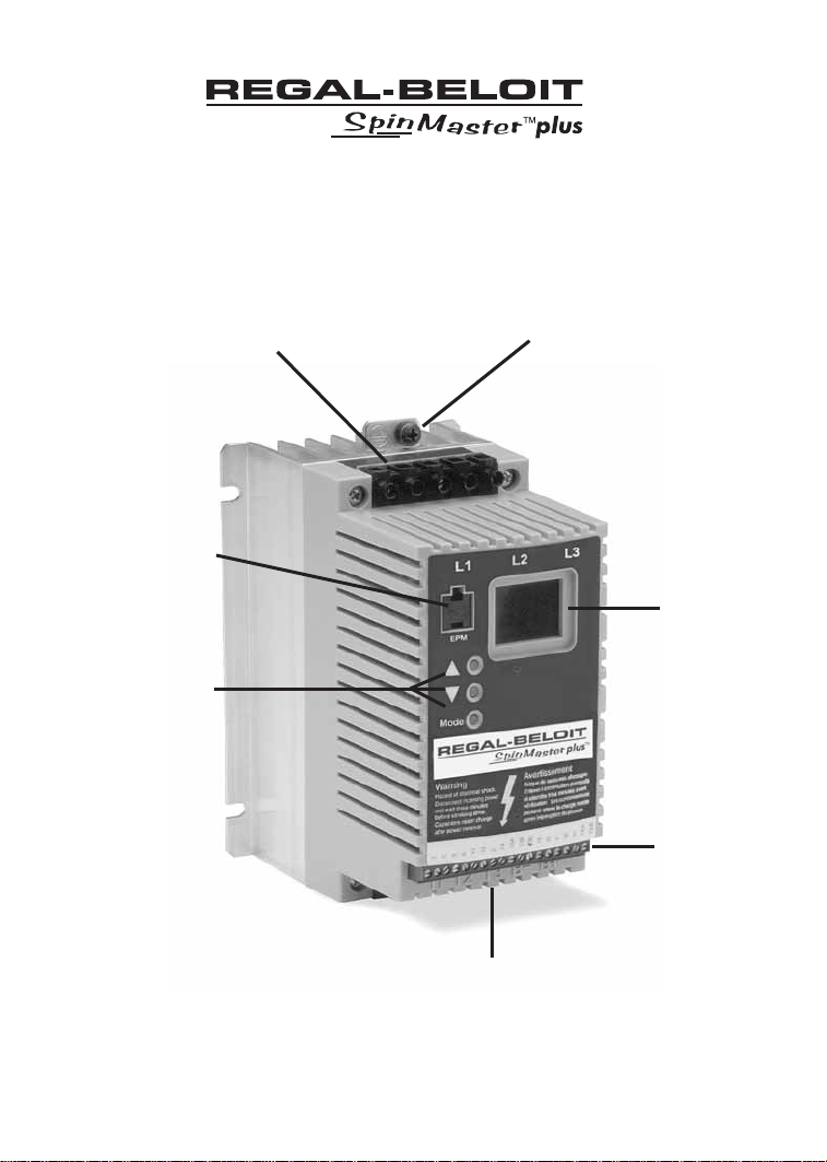
SUB-MICRO DRIVE
INPUT POWER
TERMINALS
GROUND LUG
ELECTRONIC
PROGRAMMING
MODULE (EPM)
PROGRAMMING
BUTTONS
OUTPUT (MOTOR)
TERMINALS
3-DIGIT LED
DISPLAY
CONTROL
TERMINAL
STRIP
Page 5

1.0 GENERAL
1.1 PRODUCTS COVERED IN THIS MANUAL
This manual covers the REGAL-BELOIT CORPORATION SpinMaster™ Plus Variable Frequency
Drive.
1.2 PRODUCT CHANGES
REGAL-BELOIT CORPORATION reserves the right to discontinue or make modifications to the
design of its products without prior notice, and holds no obligation to make modifications to
products sold previously. REGAL-BELOIT CORPORATION also holds no liability for losses of any
kind which may result from this action.
1.3 WARRANTY
REGAL-BELOIT CORPORATION warrants the SpinMaster™ Plus AC motor control to be free of
defects in material and workmanship for a period of twenty-four (24) months from date of
manufacture. If a SpinMaster™ Plus motor control, under normal use, becomes defective
within the stated warranty time period, contact REGAL-BELOIT’s Service Department for
instructions on obtaining a warranty replacement unit. REGAL-BELOIT CORPORATION reserves
the right to make the final determination as to the validity of a warranty claim, and sole
obligation is to repair or replace only components which have been rendered defective due
to faulty material or workmanship. No warranty claim will be accepted for components which
have been damaged due to mishandling, improper installation, unauthorized repair and/or
alteration of the product, operation in excess of design specifications or other misuse, or
improper maintenance. REGAL-BELOIT CORPORATION makes no warranty that its pr oducts ar e
compatible with any other equipment, or to any specific application, to which they may be
applied and shall not be held liable for any other consequential damage or injury arising from
the use of its products.
This warranty is in lieu of all other warranties, expressed or implied. No other
person, firm or corporation is authorized to assume, for REGAL-BELOIT
CORPORATION, any other liability in connection with the demonstration or
sale of its products.
1.4 RECEIVING
Inspect all cartons for damage which may have occurred during shipping. Carefully unpack
equipment and inspect thoroughly for damage or shortage. Report any damage to carrier
and/or shortages to supplier. All major components and connections should be examined for
damage and tightness, with special attention given to PC boards, plugs, knobs and switches.
1.5 CUSTOMER MODIFICATION
REGAL-BELOIT CORPORATION, its sales representatives and distributors, welcome the
opportunity to assist our customers in applying our products. Many customizing options are
available to aid in this function. REGAL-BELOIT CORPORATION cannot assume responsibility for
any modifications not authorized by its engineering department.
1
Page 6
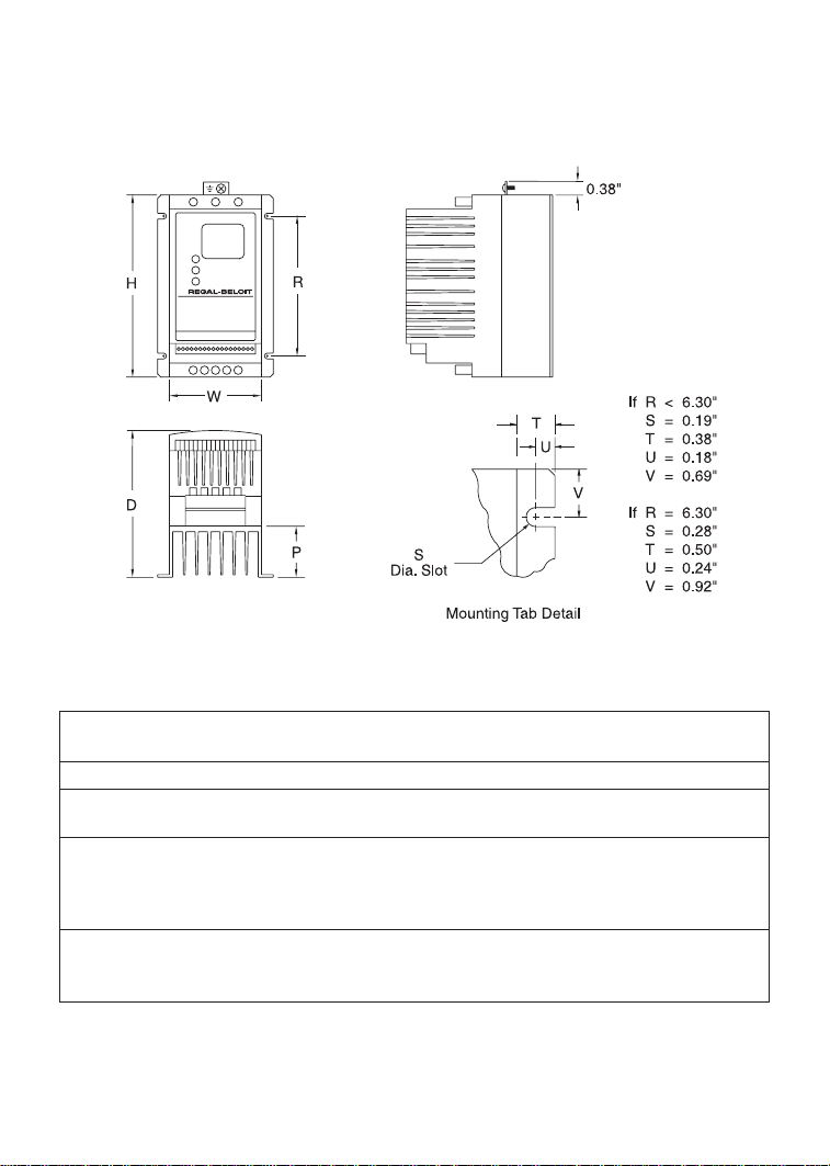
2
INPUT
HP kW VOLTAGE MODEL H W D P R
0.25 0.20 208 / 240 T310 5.75 2.88 3.94 0.80 4.37
0.5 0.37 208 /240 T312 5.75 2.88 3.94 0.80 4.37
400 / 480 T332 5.75 2.88 3.94 0.80 4.37
1 0.75 208 / 240 T314 5.75 2.88 4.74 1.60 4.37
208 / 240 T324 5.75 2.88 4.74 1.60 4.37
400 / 480 T334 5.75 2.88 4.74 1.60 4.37
480 / 590 T354 5.75 2.88 4.74 1.60 4.37
1.5 1.1 208 / 240 T315 5.75 3.76 5.24 1.90 4.37
208 / 240 T325 5.75 2.88 5.74 2.60 4.37
400 / 480 T335 5.75 2.88 5.74 2.60 4.37
2.0 SpinMaster™ Plus DIMENSIONS
Page 7
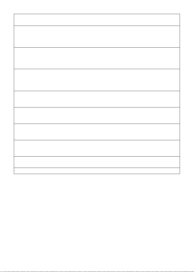
INPUT
HP kW VOLTAGE MODEL H W D P R
2 1.5 208 / 240 T316 5.75 3.76 6.74 3.40 4.37
208 / 240 T326 5.75 2.88 5.74 2.60 3.06
400 / 480 T336 5.75 2.88 5.74 2.60 4.37
480 / 590 T356 5.75 2.88 5.74 2.60 4.37
3 2.2 208 / 240 T317 5.75 3.76 6.74 3.40 3.25
208 / 240 T327 5.75 2.88 5.74 2.60 3.06
400 / 480 T337 5.75 2.88 5.74 2.60 3.06
480 / 590 T357 5.75 3.76 6.74 3.40 4.37
5 3.7 208 / 240 T318 7.75 5.02 7.18 3.40 4.81
208 / 240 T328 5.75 3.76 6.74 3.40 3.25
400 / 480 T338 5.75 3.76 6.74 3.40 3.25
480 / 590 T358 5.75 3.76 6.74 3.40 3.25
7.5 5.5 208 / 240 T329 7.75 5.02 7.18 3.40 4.81
400 / 480 T339 7.75 5.02 7.18 3.40 4.81
480 / 590 T359 7.75 5.02 7.18 3.40 4.81
10 7.5 208 / 240 T330 7.75 5.02 7.18 3.40 4.81
400 / 480 T340 7.75 5.02 7.18 3.40 4.81
480 / 590 T360 7.75 5.02 7.18 3.40 4.81
15 11 208 / 240 T331 9.75 6.68 8.00 3.60 6.30
400 / 480 T341 9.75 6.68 8.00 3.60 6.30
480 / 590 T361 9.75 6.68 8.00 3.60 6.30
20 15 208 / 240 T333 9.75 6.68 8.00 3.60 6.30
400 / 480 T342 9.75 6.68 8.00 3.60 6.30
480 / 590 T362 9.75 6.68 8.00 3.60 6.30
25 18.5 400 / 480 T343 9.75 6.68 8.00 3.60 6.30
480 / 590 T363 9.75 6.68 8.00 3.60 6.30
30 2.2 400/480 T344 9.75 6.68 8.00 3.60 6.30
3
Page 8

4
4.0 SpinMaster™ Plus SPECIFICATIONS
Storage Temperature -20° to 70° C
Ambient Operating Temperature 0° to 50° C (up to 6 kHz carrier, derate above 6 kHz)
Ambient Humidity <95% (non-condensing)
Maximum Altitude 3300 ft (1000m) above sea level (without derating)
Input Line Voltages 208/240 Vac, 400/480 Vac, 480/590 Vac
Input Voltage Tolerance +10%, -15%
Input Frequency Tolerance 48 to 62 Hz
Output Wave Form Sine Coded PWM
Output Frequency 0 - 240 Hz (consult Factory for higher output
frequencies)
Carrier Frequency 4 kHz to 10 kHz
Service Factor 1.00 (up to 6 kHz carrier, derate above 6 kHz)
Efficiency Up to 98%
Power Factor (displacement) 0.96 or better
Overload Current Capacity 150% for 60 seconds, 180% for 30 seconds
Speed Reference Follower 0 - 10 VDC, 4 - 20 mA
Control Voltage 15 VDC
Power Supply for Auxiliary Relays 50 mA at 12 VDC
Analog Outputs 0 - 10 VDC or 2 - 10 VDC: Proportional to frequency
or load
Digital Outputs Open-collector outputs: 50 mA at 30 VDC
Page 9
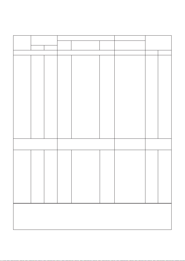
MODEL FOR MOTORS INPUT (50-60 Hz) OUTPUT HEAT LOSS
NUMBER RATED INPUT CURRENT POWER CURRENT (WATTS)
HP kW PHASE (AMPS) (kVA) (AMPS) (NOTE 6)
T310 SERIES (NOTE 3) 208/240 Vac 0 - 200/230 Vac STD THRU
T310 0.25 0.20 1 3.6/3.2 0.76 1.6/1.4 19 N/A
T310 0.25 0.20 3 1.9/1.7 0.71 1.6/1.4 19 N/A
T312 0.5 0.37 1 5.4/4.7 1.2 2.5/2.2 26 N/A
T312 0.5 0.37 3 3.1/2.7 1.1 2.5/2.2 26 N/A
T314 1 0.75 1 10.6/9.2 2.2 4.8/4.2 49 N/A
T314 1 .075 3 5.8/5.1 2.1 4.8/4.2 49 N/A
T315 1.5 1.1 1 13.9/12.0 2.9 6.9/6.0 82 N/A
T315 1.5 1.1 3 8.0/6.9 2.9 6.9/6.0 82 N/A
T316 2 1.5 1 14.8/12.9 3.1 7.8/6.8 86 N/A
T316 2 1.5 3 9.1/7.9 3.2 7.8/6.8 86 N/A
T317 3 2.2 1 19.7/17.1 4.1 11.0/9.6 130 N/A
T317 3 2.2 3 12.4/10.8 4.4 11.0/9.6 130 N/A
T318 5 3.7 1 29/26 6.1 17.5/15.2 212 N/A
T318 5 3.7 3 19.6/17.1 7.1 17.5/15.2 212 N/A
T320 - T330 SERIES
208/240 Vac 0 - 200/230 Vac
(NOTE 3)
T324 1 0.75 3 5.8/5.1 2.1 4.8/4.2 41 N/A
T325 1.5 1.1 3 8.0/6.9 2.9 6.9/6.0 69 N/A
T326 2 1.5 3 9.1/7.9 3.3 7.8/6.8 78 N/A
T327 3 2.2 3 12.4/10.8 4.5 11.0/9.6 117 N/A
T328 5 3.7 3 19.6/17.1 7.1 17.5/15.2 187 N/A
T329 7.5 5.5 3 28/25 10.3 25/22 286 N/A
T330 10 7.5 3 34/32 13.1 30/28 379 N/A
T331 15 11 3 54/48 20.0 48/42 476 N/A
T333 20 15 3 65/61 25.4 58/54 648 N/A
NOTE 3: The higher current ratings are for 208 Vac input and the lower current ratings
are for 240 Vac input.
NOTE 6: STD = standar d unit. V alues ar e worst-case (not typical) for 6 kHz carrier fr equency
at full speed and full load.
5
5.0 SpinMaster™ Plus RATINGS
Page 10
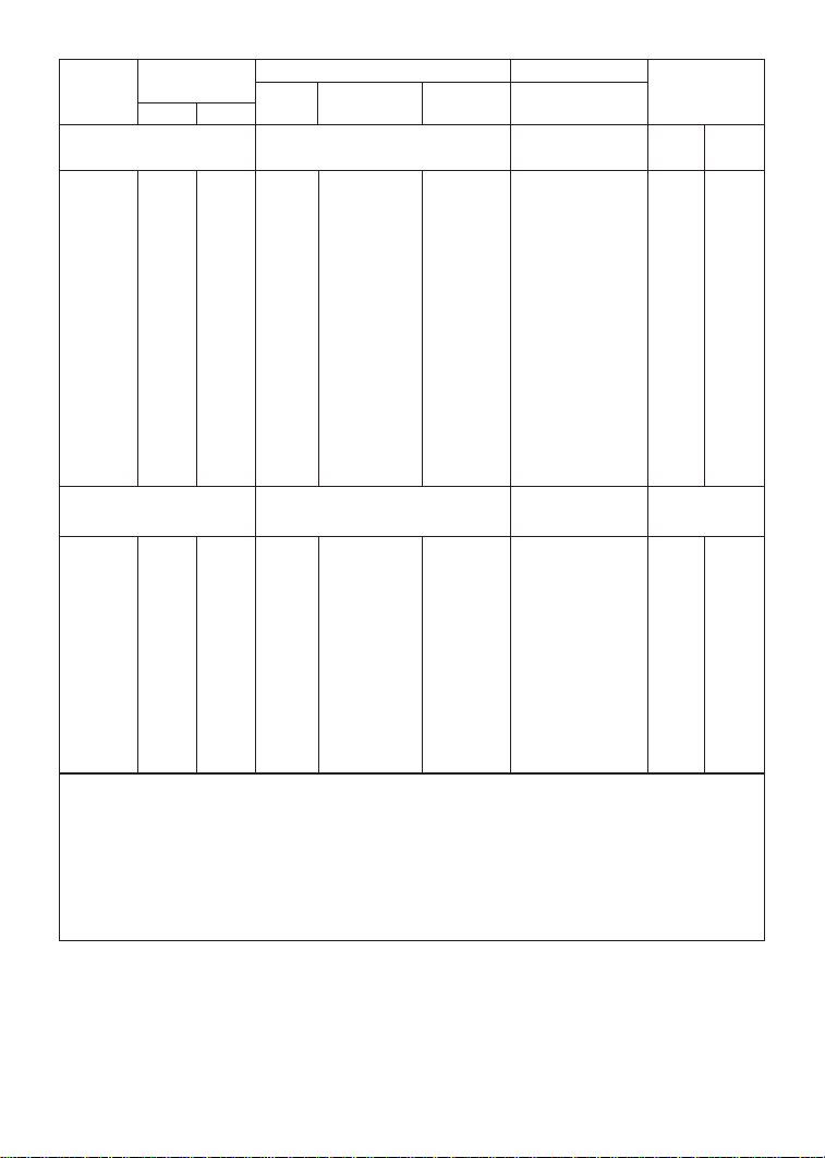
MODEL FOR MOTORS INPUT (50-60 Hz) OUTPUT HEAT LOSS
NUMBER RATED INPUT CURRENT POWER CURRENT (WATTS)
HP kW PHASE (AMPS) (kVA) (AMPS) (NOTE 6)
T330 - T340 SERIES
400/480 Vac 0 - 400/460 Vac STD THRU
(NOTE 4)
T332 0.5 0.37 3 1.6/1.4 1.1 1.3/1.1 26 N/A
T334 1 0.75 3 2.9/2.5 2.1 2.4/2.1 40 N/A
T335 1.5 1.1 3 4.0/3.6 3.0 3.4/3.0 56 N/A
T336 2 1.5 3 4.6/4.0 3.3 3.9/3.4 67 N/A
T337 3 2.2 3 6.2/5.4 4.5 5.5/4.8 100 N/A
T338 5 3.7 3 9.8/8.6 7.1 8.7/7.6 168 N/A
T339 7.5 5.5 3 14.2/12.4 10.3 12.6/11.0 254 N/A
T340 10 7.5 3 18.1/15.8 13.1 16.1/14.0 310 N/A
T341 15 11 3 27/24 20.0 24/21 390 N/A
T342 20 15 3 35/31 25.8 31/27 530 N/A
T343 25 18.5 3 44/38 31.6 39/34 648 N/A
T344 30 2.2 3 53/45 37.4 46/40 770 N/A
T350 - T360 SERIES
480/590 Vac 0 - 460/575 Vac
(NOTE 5)
T354 1 0.75 3 2.2/2.0 1.9/2.0 1.9/1.7 40 N/A
T356 2 1.5 3 4.0/3.5 3.3/3.6 3.4/3.0 67 N/A
T357 3 2.2 3 4.7/4.7 3.9/4.8 4.2/4.2 100 N/A
T358 5 3.7 3 7.4/7.4 6.1/7.5 6.6/6.6 168 N/A
T359 7.5 5.5 3 11.2/11.2 9.3/11.4 9.9/9.9 254 N/A
T360 10 7.5 3 13.7/13.7 11.4/14.0 12.2/12.2 310 N/A
T361 15 11 3 22/22 18.3/22.5 19.0/19.0 390 N/A
T362 20 15 3 27/27 22.4/27.6 24/24 530 N/A
T363 25 18.5 3 31/31 25.8/31.7 27/27 648 N/A
NOTE 4: The higher current ratings are for 400 Vac input and the lower current ratings
are for 480 Vac input.
NOTE 5: The higher current ratings for for 480 Vac input and the lower current ratings are
for 590 Vac input.
NOTE 6: STD = standar d unit. V alues ar e worst-case (not typical) for 6 kHz carrier fr equency
at full speed and full load.
6
Page 11

6.0 INSTALLATION
NOTE: SpinMaster™ Plus drives are intended for inclusion within other equipment, by
professional electrical installers. They are not intended for stand-alone operation.
DRIVES MUST NOT BE INSTALLED WHERE SUBJECTED TO ADVERSE
ENVIRONMENTAL CONDITIONS SUCH AS: COMBUSTIBLE, OILY, OR HAZARDOUS VAPORS OR
DUST; EXCESSIVE MOISTURE OR DIRT; VIBRATION; EXCESSIVE AMBIENT TEMPERATURES.
CONSULT REGAL-BELOIT CORPORATION FOR MORE INFORMATION ON THE SUITABILITY OF A
DRIVE TO A PARTICULAR ENVIRONMENT.
SpinMaster™ Plus models are suitable for UL pollution degree 2 environment only, and MUST
be installed in an electrical enclosure which will provide complete mechanical protection and
will maintain the internal temperature within the drive’s ambient operating temperature rating.
All drives models MUST be mounted in a vertical position for proper heatsink cooling.
Maintain a minimum spacing around the drive of at least 1 inch (25mm) on each side and 2
inches (50mm) on the top and bottom for units rated up to 5 HP (3.7kW). For units rated 7.5
- 30 HP (5.5 - 22 kW), maintain at least 2 inches (50mm) on each side and 4 inches (100mm)
on the top and bottom. Allow more spacing if the drive is mounted next to other
heat-producing equipment. Do not mount drives above other drives or heat producing
equipment. Fans or blowers should be used to insure proper cooling in tight quarters.
In order to properly size an enclosur e, the heat generated by the drive(s) must be known. Refer
to the HEAT LOSS columns in Section 5.0 - SpinMaster™ Plus RATINGS. The STD column is for
standard units. An enclosure manufacturer can then determine the required enclosure size
based on the total heat generated inside the enclosure (from the drive(s) and other heat
sources), the maximum allowable temperature inside the enclosure, the maximum ambient
temperature outside the outside the enclosure, and the enclosure properties.
The SpinMaster™ Plus is UL approved for solid state motor overload protection. Therefore, a
separate thermal overload relay is not required for single motor applications.
6.1 INSTALLATION AFTER A LONG PERIOD OF STORAGE
Severe damage to the drive can result if it is operated after a long period of
storage or inactivity without reforming the DC bus capacitors!
If input power has not been applied to the drive for a period of time exceeding three years
(due to storage etc), the electrolytic DC bus capacitors within the drive can change internally,
resulting in excessive leakage current. This can result in premature failure of the capacitors if
the drive is operated after such a long period of inactivity or storage.
In order to reform the capacitors and prepare the drive for operation after a long period of
inactivity, apply input power to the drive for 8 hours prior to actually operating the motor.
7
Page 12

8
6.2 EXPLOSION PROOF APPLICATIONS
Explosion proof motors that are not rated for inverter use lose their certification when used for
variable speed. Due to the many areas of liability that may be encountered when dealing with
these applications, the following statement of policy applies:
“REGAL-BELOIT CORPORATION inverter products ar e sold with no warranty of
fitness for a particular purpose or warranty of suitability for use with explosion proof motors. REGAL-BELOIT CORPORATION accepts no responsibility
for any direct, incidental or consequential loss, cost, or damage that may arise
through the use of its AC inverter products in these applications. The
purchaser expressly agr ees to assume all risk of any loss, cost, or damage that
may arise from such application.”
7.0 INPUT AC POWER REQUIREMENTS
Hazard of electrical shock! Capacitors retain charge after power is removed.
Disconnect incoming power and wait until the voltage between terminals B+ and B- is 0 VDC
before servicing the drive.
The input voltage must match the nameplate voltage rating of the drive. Voltage fluctuation
must not vary by greater than 10% overvoltage or 15% undervoltage.
NOTE: Drives with dual input voltage ratings must be programmed for the proper supply
voltage (refer to Parameter 01 - LINE VOLTAGE SELECTION in Section 15.0 - DESCRIPTION OF
PARAMETERS).
The drive is suitable for use on a circuit capable of delivering not more than 5,000 RMS
symmetrical amperes at 5 HP (3.7kW), and below, and 18,000 RMS symmetrical amperes at
7.5 HP (5.5kW) and above, at the drive’s rated voltage.
If the kVA rating of the AC supply transformer is greater than 10 times the input kVA rating of
the drive(s), an isolation transformer or 2-3% input line reactor must be added to the line side
of the drive(s).
Three phase voltage imbalance must be less than 2.0% phase to phase. Excessive phase to
phase imbalance can cause severe damage to the drive’s power components.
Motor voltage should match line voltage in normal applications. The drive’s maximum output
voltage will equal the input voltage. Use extreme caution when using a motor with a voltage
rating which is different from the input line voltage.
Page 13

9
7.1 INPUT VOLTAGE RATINGS
T310 through T318 drives are rated for 208/240 Vac, single or three phase, 50-60 Hz input.
The drive will function with input voltages of 208 to 240 Vac (+10%, -15%), at 48 to 62 Hz.
T324 through T331, and T333 drives are rated for 208/240 V ac, thr ee phase, 50-60 Hz input.
The drive will function with input voltage of 208 to 240 Vac (+10%, -15%), at 48 to 62 Hz.
T332, T334 through T344 drives are rated for 400/480 V ac, three phase, 50-60 Hz input. The
drive will function with input voltages of 400 to 480 Vac (+10%, -15%), at 48 to 62 Hz.
T354 through T363 drives are rated for 480/590 Vac, three phase, 50-60 Hz input, and will
function with input voltages of 480 to 590 Vac (+10%, -15%), at 48 to 62 Hz.
NOTE: Parameter 01 - LINE VOLTAGE SELECTION must be programmed according to the
applied input voltage. See Section 15.0 - DESCRIPTION OF PARAMETERS.
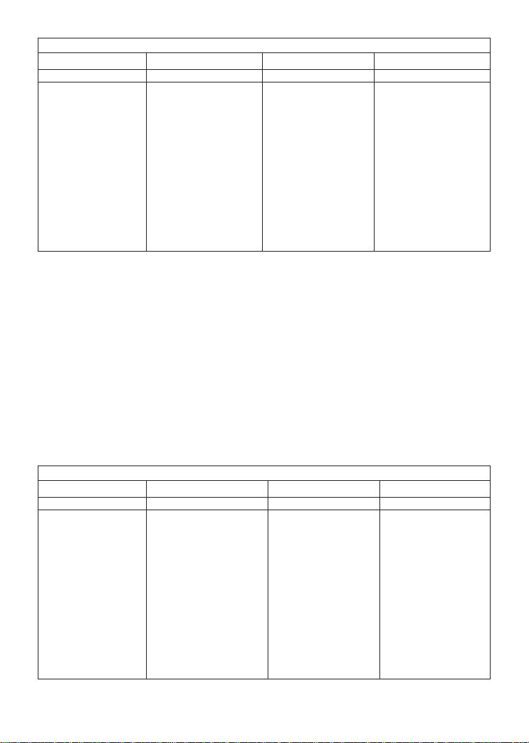
7.2 INPUT FUSING AND DISCONNECT REQUIREMENTS
A circuit breaker or a disconnect switch with fuses must be provided in accordance with the
National Electric Code (NEC) and all local codes. Refer to the following tables for proper
fuse/circuit breaker ratings and wire sizes.
The SpinMaster™ Plus drive is capable of withstanding up to 150% current overload for 60
seconds. Select a fuse or magnetic trip circuit breaker rated at 1.5 times the input current
rating of the drive (the minimum size should be 10 amps, regardless of input current rating).
Refer to Section 5.0 - SpinMaster™ Plus RATINGS.
Minimum voltage rating of the protection device should be 250 Vac for 208/240 Vac rated
drives, and 600 Vac for 400/480 Vac and 480/590 Vac drives.
NOTE 1: Applicable national and local electrical codes take precedence over
recommendations in the tables on the following page.
Page 14
NOTE 2: Use UL Class CC or Class T fast-acting, current limiting type fuses. Select fuses with
low 12 T values, rated at 200,000 AIC. Recommended fuses are Bussman KTK-R, JJN and JJS.
Similar fuses with equivalent ratings by other manufacturers may also be acceptable.
NOTE 3: When using a Pulse Current or Universal Current sensitive Earth Leakage Circuit
Breaker (ELCB). The detection level must be rated 30mA or greater. Observe the following
when using ELCB’s:
1. Only install the ELCB between the supply mains and drive controller.
2. The ELCB can be activated by:
• Capacitive leakage currents between the cable screens during operation
(especially with long screened motor cables)
• Connecting several drives to the mains at the same time.
• Additional RFI filters
10
INPUT FUSE & CIRCUIT BREAKER RATINGS
208/240 Vac, 1 phase 208/240 Vac, 3 phase 400/480 Vac, 3 phase 480/590 Vac, 3 phase
MODEL RATING MODEL RATING MODEL RATING MODEL RATING
T310 10A T310 10A
T312 10A T312 10A T332 10A
T314 15A T314 & T324 10A T334 10A T354 10A
T315 20A T315 & T325 12 / 10A T335 10A
T316 25 / 20A T316 & T326 15 / 12A T336 10A T356 10A
T317 30 / 25A T317 & T327 20 / 15A T337 10A T357 10A
T318 45 / 40A T318 & T328 30 / 25A T338 15A T358 12A
T329 45 / 40A T339 20A T359 20A
T330 50 / 50A T340 30 / 25A T360 20A
T331 80 / 75A T341 40 / 35A T361 30A
T333 100 / 90A T342 50 / 45A T362 40A
T343 70 / 60A T363 45A
T344 80 / 70A
WIRE SIZE REQUIREMENTS
208/240 Vac, 1 phase 208/240 Vac, 3 phase 400/480 Vac, 3 phase 480/590 Vac, 3 phase
MODEL AWG mm2 MODEL AWG mm2 MODEL AWG mm2 MODEL AWG mm2
T310 14 1.5 T310 14 1.5
T312 14 1.5 T312 14 1.5 T332 14 1.5
T314 14 1.5 T314 & T324 14 1.5 T334 14 1.5 T354 14 1.5
T315 12 2.5 T315 & T325 14 1.5 T335 14 1.5
T316 12 2.5 T316 & T326 14 1.5 T336 14 1.5 T356 14 1.5
T317 10 4.0 T317 & T327 12 2.5 T337 14 1.5 T357 14 1.5
T318 8 6.0 T318 & T328 10 4.0 T338 14 1.5 T358 14 1.5
T329 8 6.0 T339 12 2.5 T359 14 1.5
T330 8 10 T340 10 4.0 T360 12 2.5
T331 6 16 T341 8 6.0 T361 10 4.0
T333 4 25 T342 8 10 T362 10 4.0
T343 6 16 T363 8 10
T344 6 16
Page 15
7.3 INSTALLATION ACCORDING TO EMC REQUIREMENTS
The SpinMaster™ Plus Series can be installed to meet the
European standards for Electromagnetic Compatibility (EMC)
requirements. These requirements govern the permissible
electromagnetic emissions and immunity, both radiated and
conducted, of a drive system.
The EMC requirements apply to the final installation in its
entirety, not to the individual components used. Because ever y
installation is different, the recommended installation should
follow these guidelines as a minimum. Additional equipment
(such as ferrite core absorbers on power conductors) or
alternative wiring practices may be required to meet
conformance in some installations.
Filter: The input to the drive (or group of drives) must include a
filter to reduce the electrical noise reflected back to the AC Line.
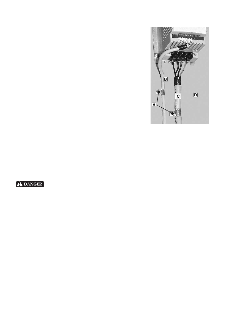
Installation: Shielded cable must be used for all control and power cables and exposed wiring
must be kept as short as possible. The figure to the right shows the control cable (B) and motor
cable (C) with the shield grounded with clamps (A) to a grounded, electrically conductive
mounting panel (D). The motor cable must be of a low capacitance specification:
core/core < 75 pF/m, core/shield < 150 pF/m
8.0 POWER WIRING
Hazard of electrical shock! Capacitors retain charge after power is removed.
Disconnect incoming power and wait until the voltage between terminals B+ and B- is 0 VDC
before servicing the drive.
Note drive input and output current ratings and check applicable electrical codes for required
wire type and size, grounding requirements, over-current protection, and incoming power
disconnect, before wiring the drive. Size conservatively to minimize voltage drop.
Strip off 0.24 inches (6mm) for the .25 - 5 HP, .35 inches (9mm) for the 7.5 - 10 HP and .5
inches (13mm) for the 15 HP and larger of insulation for input power, output power, and
DC Bus wiring. The input power, output power, and DC Bus terminals must be tightened
to a torque of 4.5 lb-in (0.5 Nm) for the .25 - 5 HP, 10 lb-in (1.2 Nm) for the 7.5 - 10 HP and
18 lb-in (2.0 Nm) for the 15 HP and larger.
Input fusing and a power disconnect switch or contactor MUST be wired in series with
terminals L1, L2, and L3 for three phase input models. For 208/240 Vac single phase input
models, use terminals L1 and L2. This disconnect must be used to power down the drive when
servicing, or when the drive is not to be operated for a long period of time, but should not be
used to start and stop the motor.
11
Page 16

Repetitive cycling of a disconnect or input contactor (more than once every
two minutes) may cause damage to the drive.
8.1 INPUT AND OUTPUT WIRING
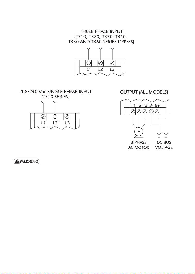
If the drive is rated for single and three phase input (T310 models), wire to terminals L1 and
L2 for single phase input, or wire to terminals L1, L2, and L3 for three phase input.
If the drive is rated for three phase input, wire the input to terminals L1, L2, and L3.
All three power output wires, from terminals T1, T2, and T3 to the motor, must be kept
tightly bundled and run in a separate conduit away from all other power and control wiring.
It is not recommended to install contactors or disconnect switches between the drive and
motor. Operating such devices while the drive is running can potentially cause damage to the
drive’s power components. If such a device is required, it should only be operated when the
drive is in a STOP state. If there is potential for the device to be opened while the drive is
running, the drive must be programmed for COAST to stop (see Parameter 4 - STOP METHOD),
and an auxiliary contact on the device must be interlocked with the drive’s run circuit. This will
give the drive a stop command at the same time the device opens, and will not allow the drive
to start again until the device is closed.
12
Page 17
13
Do not connect incoming AC power to output terminals T1, T2, or T3. Severe
damage to the drive will result.
NOTES:
1. WIRE AND GROUND IN ACCORDANCE WITH NEC OR CEC, AND ALL APPLICABLE LOCAL
CODES.
2. Motor wires MUST be run in a separate steel conduit away from control wiring and
incoming AC power wiring.
3. Do not install contactors between the drive and the motor without consulting REGALBELOIT CORPORATION for more information. Failur e to do so may r esult in drive damage.
4. Use only UL and CSA listed and approved wire.
5. Minimum wire voltage ratings: 300 V for 120, 208 and 240 Vac systems, and 600 V for
400, 480, and 590 Vac systems.
6. Wire gauge must be based on a minimum of 125% of the rated input/output current of
the drive, and a minimum 75° C insulation rating. Use copper wire only.
9.0 SpinMaster™ Plus POWER WIRING DIAGRAM
Page 18

14
10.0 CONTROL WIRING
10.1 CONTROL WIRING VS. POWER WIRING
External control wiring MUST be run in a separate conduit away from all other input and
output power wiring. If control wiring is not kept separate from power wiring, electrical noise
may be generated on the control wiring that will cause erratic drive behavior. Use twisted
wires or shielded cable grounded at the drive chassis ONLY. Recommended control wire is
Belden 8760 (2-wire) or 8770 (3-wire), or equivalent.
Strip off 0.20 to 0.25 inches (5 to 6mm) of insulation for control wiring and torque the
terminals to 2 lb-in (0.2 Nm). Be careful not to overtorque the control terminals, as this will
cause damage to the terminal strip. This is not covered under warranty and can only be
repaired by replacing the control board.
10.2 TB-2: CIRCUIT COMMON
The TB-2 terminals are used as circuit common for the start/stop, forward/reverse, input select,
local/remote, analog input, and analog output functions. There are three TB-2 terminals
available on the terminal strip, and they are all internally connected to each other on the main
control board. If necessary TB-2 may be connected to chassis ground.
NOTE: TB-2 must be connected to chassis ground when using serial communications.
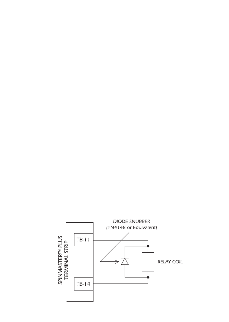
10.3 SURGE SUPPRESSION ON RELAYS
Current and voltage surges and spikes in the coils of contactors, relays, solenoids, etc, near or
connected to the drive, can cause erratic drive operation. Therefore, a snubber circuit should
be used on coils associated with the drive. For AC coils, snubbers should consist of a resistor
and a capacitor in series across the coil. For DC coils, a free-wheeling or flyback diode should
be placed across the coil. Snubbers are typically available fr om the manufacturer of the device.
10.4 START/STOP CONTROL
There are various control schemes that allow for 2-wire and 3-wire Start/Stop circuits. Refer to
the wiring diagrams in Section 11.0 - SpinMaster™ Plus CONTROL WIRING DIAGRAMS.
10.5 SPEED REFERENCE SIGNALS
The drive allows for three analog speed reference inputs:
SPEED POT Connect the wiper of a speed pot to terminal TB-5, and connect the high and
low end leads to terminals TB-6 and TB-2, respectively. The speed pot can be
2.5kΩ up to 10kΩ.
0-10 VDC Wire the positive to terminal TB-5 and the negative to terminal TB-2. TB-5 input
impedance is 120 kilohms.
4-20 mA Wire the positive to terminal TB-25 and the negative to terminal TB-2. TB-25
input impedance is 100 ohms.
Page 19
15
10.6 SPEED REFERENCE SELECTION
If an analog speed reference input is used to control the drive speed, terminal TB-13A, 13B,
or 13C (Parameter 10, 11, or 12) may be programmed as the input select for the desired
analog input signal. When that TB-13 terminal is then closed to TB-2, the drive will follow the
selected analog speed reference input.
If an analog speed reference input is not selected on the terminal strip using TB-13A, 13B, or
13C, speed control will default to STANDARD mode, which is governed by the setting of
Parameter 05 - STANDARD SPEED SOURCE. The STANDARD SPEED SOURCE can be the L and
M buttons on the front of the drive, PRESET SPEED #1(Parameter 31), a 0-10 VDC signal, or a
4-20 mA signal.
0-10 VDC and 4-20 mA INPUT SIGNALS
TB-13A, TB-13B, and TB-13C can all be programmed to select a 0-10 VDC or 4-20 mA analog
speed reference input.
PRESET SPEEDS
TB-13A can be programmed to select PRESET SPEED #1, TB-13B to select PRESET SPEED #2,
and TB-13C to select PRESET SPEED #3. There are a total of seven preset speeds, which are
activated by different combinations of contact closures between TB-13A, 13B, 13C and TB-2.
Refer to Parameters 31-37 in Section 15.0 - DESCRIPTION OF PARAMETERS.
JOG
TB-13B can be programmed to select either JOG FORWARD or JOG REVERSE. The Jog speed
is set by PRESET SPEED #2. Close TB-13B to TB-2 to JOG, and open the contact to STOP.
When operating in JOG mode, the STOP terminal (TB-1) and the STOP key (on
the optional remote keypad) WILL NOT stop the drive. To stop the drive, remove the JOG
command.
JOG REVERSE will operate the drive in reverse rotation even if ROTATION
DIRECTION (Parameter 17) is set to FORWARD ONLY.
NOTE: If the drive is commanded to JOG while running, the drive will enter JOG mode and
run at PRESET SPEED #2. When the JOG command is removed, the drive will STOP.
MOTOR OPERATED POT (MOP) / FLOATING POINT CONTROL
TB-13B and TB-13C are used for this function, which controls the drive speed using contacts
wired to the terminal strip. Program TB-13B for DECREASE FREQ (05), and pr ogram TB-13C for
INCREASE FREQ (05). Closing TB-13B to TB-2 will cause the speed setpoint to decrease until
the contact is opened. Closing TB-13C to TB-2 will cause the speed setpoint to increase
until the contact is opened. The INCREASE FREQ function will only operate while the drive is
running.
Page 20
16
NOTE: If TB-13A, TB-13B, and TB-13C ar e all pr ogrammed to select speed r efer ences, and two
or three of the terminals are closed to TB-2, the higher terminal has priority and will override
the others. For example, if TB-13A is programmed to select 0-10 VDC, and TB-13C is
programmed to select PRESET SPEED #3, closing both terminals to TB-2 will cause the drive to
respond to PRESET SPEED #3, because TB-13C overrides TB-13A.
The exception to this is the MOP function, which requires the use of TB-13B and TB-13C. This
leaves TB-13A to be used for some other function. If TB-13A is programmed for a speed
reference, and TB-13A is closed to TB-2, TB-13A will override the MOP function.
10.7 ANALOG OUTPUT SIGNALS
Terminal TB-30 can provide a 0-10 VDC or a 2-10 VDC signal proportional to output frequency
or load, and TB-31 can provide the same signals proportional to load only. The 2-10 VDC
signal can be converted to a 4-20 mA signal using a resistor in series with the signal such
that the total load resistance is 500 Ohms. Refer to Parameters 08 and 09 in Section 15.0 DESCRIPTION OF PARAMETERS.
NOTE: These analog output signals cannot be used with “loop-powered” devices that derive
power from a 4-20 mA signal.
10-8 DRIVE STATUS DIGITAL OUTPUTS
There are two open-collector outputs at terminals TB-14 and TB-15. The open-collector circuits
are current-sinking types rated at 30 VDC and 50 mA maximum.
The open-collector outputs can be programmed to indicate any of the following: RUN, FAULT,
INVERSE FAULT, FAULT LOCKOUT, AT SPEED, ABOVE PRESET SPEED #3, CURRENT LIMIT, AUTO
SPEED MODE, and REVERSE. Refer to Parameters 06 and 13 in Section 15.0 - DESCRIPTION
OF PARAMETERS.
The diagram below illustrates how the 12 VDC power supply at TB-11 can be used with the
open-collector output to drive an external relay:
Page 21
17
11.0 SpinMaster™ Plus CONTROL WIRING DIAGRAMS
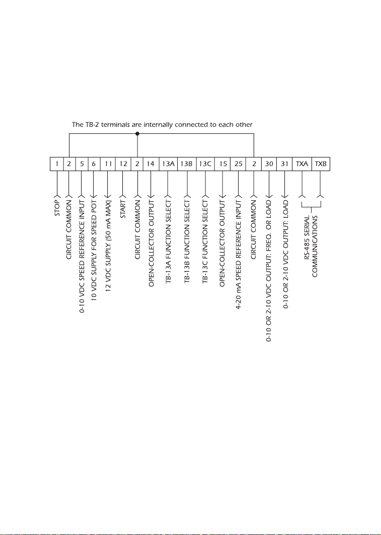
11.1 SpinMaster™ Plus TERMINAL STRIP
Shown below is the terminal strip on the main control board, along with a brief description of
the function of each terminal.
NOTE: The function of terminals TB-13A, TB-13B, TB-13C, TB-14, TB-15, TB-30, and TB-31 are
dependent on the programming of certain parameters. Refer to Section 15.0 - DESCRIPTION
OF PARAMETERS.
Additional information on operating the drive from the terminal strip can be found in Section
10.0. The following diagrams provide a quick refer ence to wir e the drive for the most common
configurations.
Page 22
18
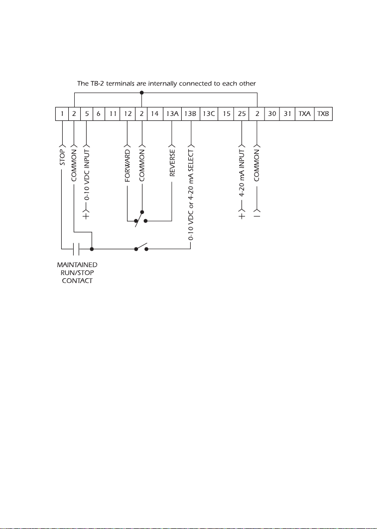
11.2 TWO-WIRE START/STOP CONTROL
Shown below is the wiring diagram for a typical two-wire start/stop control scheme, using one
maintained contact (such as that from a PLC) for RUN and STOP commands.
NOTES:
1. Close TB-1 to TB-2 to RUN and open TB-1 to TB-2 to STOP.
2. If reverse direction is also required, ROTATION DIRECTION (Parameter 17) must be set to
FORWARD AND REVERSE (02), and TB-13A (Parameter 10) must be set to START REVERSE
(06). If reverse direction is not required, TB-12 must be wired directly to
TB-2.
3. For 0-10 VDC or 4-20 mA speed control, use one of the following methods:
1. Program one of the TB-13 terminals (13A, 13B, or 13C) for 0-10 VDC (02) or 4-20
mA (03). When that TB-13 terminal is closed to TB-2, the drive will respond to the
selected speed reference signal. If that TB-13 terminal is not closed to TB-2, the drive
will respond to the speed control source selected in Parameter 05 - STANDARD
SPEED SOURCE. This method must be used if it is necessary to toggle between two
speed sources.
2. Program Parameter 05 - STANDARD SPEED SOURCE for 0-10 VDC (03) or 4-20 mA
(04). This method is preferable if only one speed source is required, as this method
leaves the TB-13 terminals free to be used for other functions.
Page 23
19
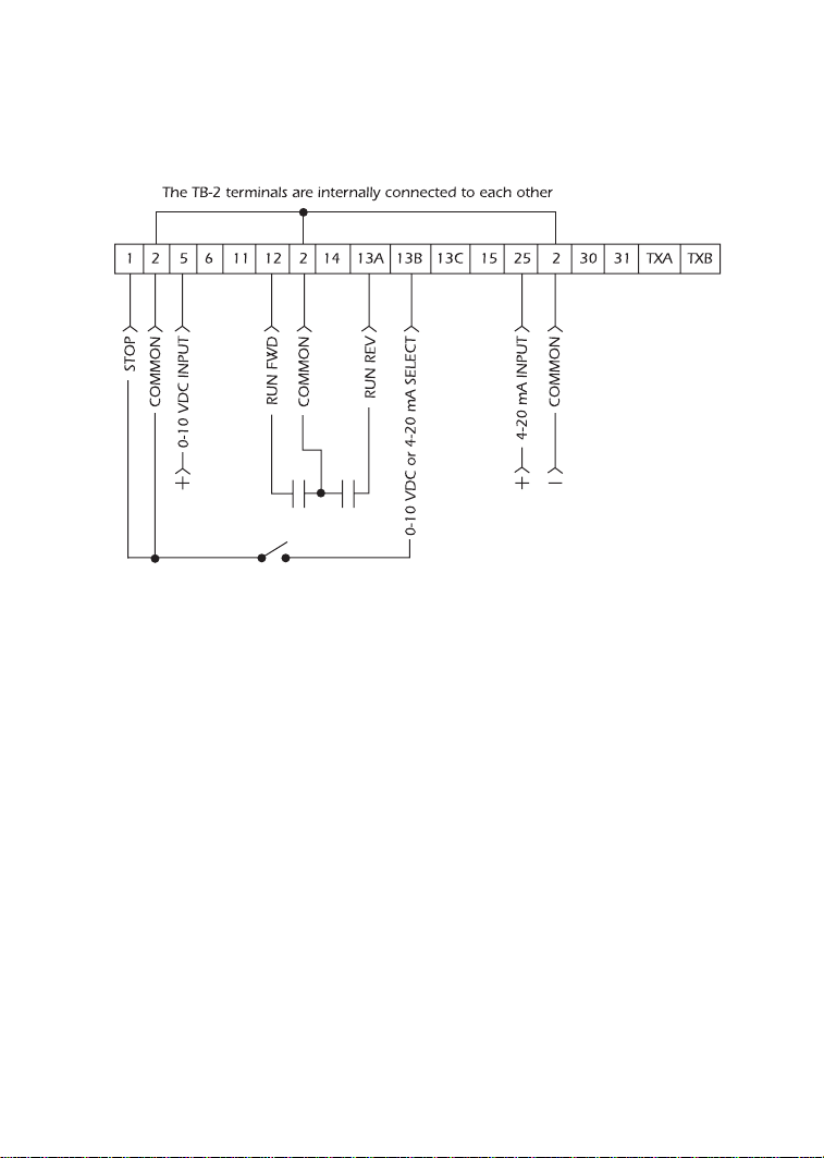
11.3 ALTERNATE TWO-WIRE START/STOP CONTROL
Shown below is the wiring diagram for an alternate two-wire start/stop control scheme, using
one maintained contact for RUN FORWARD and another maintained contact for RUN
REVERSE.
NOTES:
1. For this control scheme, TB-13A MUST be set to RUN REVERSE (05), even if REVERSE
direction is not required. Refer to Parameter 10 - TB13A FUNCTION.
2. Close TB-12 to TB-2 to RUN and open TB-12 to TB-2 to STOP.
3. If reverse direction is also required, ROTATION DIRECTION (Parameter 17) must be set to
FORWARD AND REVERSE (02). Close TB-13A to TB-2 to RUN in REVERSE, and open
TB-13A to TB-2 to STOP. If TB-12 and TB-13A are closed to TB-2, the drive will STOP.
4. For 0-10 VDC or 4-20 mA speed control, use one of the following methods:
1. Program one of the TB-13 terminals (13A, 13B, or 13C) for 0-10 VDC (02) or 4-20
mA (03). When that TB-13 terminal is closed to TB-2, the drive will respond to the
selected speed reference signal. If that TB-13 terminal is not closed to TB-2, the drive
will respond to the speed control source selected in Parameter 05 - STANDARD
SPEED SOURCE. This method must be used if it is necessary to toggle between two
speed sources.
2. Program Parameter 05 - STANDARD SPEED SOURCE for 0-10 VDC (03) or 4-20 mA
(04). This method is preferable if only one speed source is required, as this method
leaves the TB-13 terminals free to be used for other functions.
Page 24
20
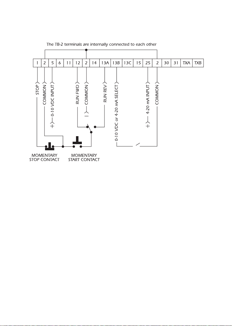
11.4 THREE-WIRE START/STOP CONTROL
Shown below is the wiring diagram for a typical three-wire start/stop control scheme, using
momentary contacts (such as pushbuttons) for START and STOP commands.
NOTES:
1. Momentarily close TB-12 to TB-2 to START the drive, and momentarily open TB-1 to TB-2
to STOP the drive.
2. If reverse direction is also required, ROTATION DIRECTION (Parameter 17) must be set to
FORWARD AND REVERSE (02), and TB-13A (Parameter 10) must be set to START REVERSE
(06). If the FWD/REV switch is changed while the drive is running, the drive will not
change direction until the START button is pushed. If reverse direction is not
required, the other side of the START pushbutton must be wired directly
to TB-12.
3. For 0-10 VDC or 4-20 mA speed control, use one of the following methods:
1. Program one of the TB-13 terminals (13A, 13B, or 13C) for 0-10 VDC (02) or 4-20
mA (03). When that TB-13 terminal is closed to TB-2, the drive will respond to the
selected speed reference signal. If that TB-13 terminal is not closed to TB-2, the drive
will respond to the speed control source selected in Parameter 05 - STANDARD
SPEED SOURCE. This method must be used if it is necessary to toggle between two
speed sources.
2. Program Parameter 05 - STANDARD SPEED SOURCE for 0-10 VDC (03) or 4-20 mA
(04). This method is preferable if only one speed source is required, as this method
leaves the TB-13 terminals free to be used for other functions.
Page 25
21
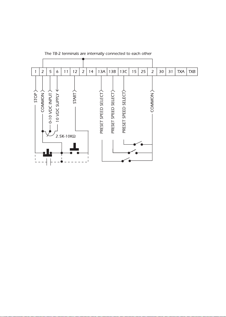
11.5 SPEED POT AND PRESET SPEED CONTROL
Shown below is the wiring for SPEED POT and/or PRESET SPEED control, and either a two-wir e
or three-wire start/stop circuit:
NOTES:
1. Program the PRESET SPEEDS (Parameters 31-37) to the desired values.
2. Program TB-13A (Parameter 10) to PRESET SPEED #1 (04). TB-13B (parameter 11) to
PRESET SPEED #2 (04), and TB-13C (Parameter 12) to PRESET SPEED #3 (04). To select a
preset speed, close the appropriate TB-13 terminal(s) to TB-2 (refer to Parameters 31-37
for the Preset Speed Activation table).
3. If reverse rotation is also required, TB-13A cannot be used as a PRESET SPEED SELECT.
TB-13A must be programmed to select RUN REVERSE (05) or START REVERSE (06), leaving
only TB-13B and TB-13C to select preset speeds.
4. For speed pot control, program Parameter 05 - STANDARD SPEED SOURCE for 0-10 VDC
(03). If none of the preset speeds are selected (all of the TB-13 terminals are open), the
drive will respond to the speed pot.
Page 26
22
12.0 INITIAL POWER UP AND MOTOR ROTATION
DO NOT connect incoming AC power to output terminals T1, T2, and T3!
Severe damage to the drive will result. Do not continuously cycle input power to the drive
more than once every two minutes. Damage to the drive will result.
Hazard of electrical shock! Wait three minutes after disconnecting incoming
power before servicing drive. Capacitors retain charge after power is removed.
Severe damage to the drive can result if it is operated after a long period of
storage or inactivity without reforming the DC bus capacitors!
If input power has not been applied to the drive for a period of time exceeding three
years (due to storage, etc), the electrolytic DC bus capacitors within the drive can change internally, resulting in excessive leakage current. This can result in premature failure of the capacitors if the drive is operated after such a long period of inactivity or storage.
In order to reform the capacitors and prepare the drive for operation after a long period of
inactivity, apply input power to the drive for 8 hours prior to actually operating the motor.
Before attempting to operate the drive, motor, and driven equipment, be sure all procedures
pertaining to installation and wiring have been properly followed.
Disconnect the driven load from the motor. Verify that the drive input terminals (L1, L2, and
L3) are wired to the proper input voltage per the nameplate rating of the drive.
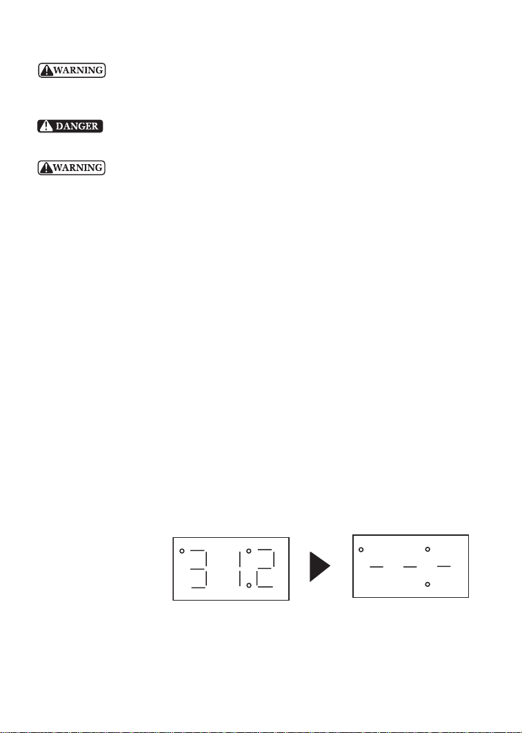
Energize the incoming power line. The LED display will flash a three digit number (312 in the
example below) that identifies the parameter version contained in the drive. The display should
then read “- - -”, which indicates that the drive is in a STOP condition. This is shown below:
Apply input power
Display flashes parameter
version (300-399)
Display then reads “- - -”
Page 27

23
Follow the procedure below to check the motor rotation. This procedure assumes that the
drive has been powered up for the first time, and that none of the parameters have been
changed.
1. Use the M button to decrease the speed setpoint to 00.0 Hz. The left decimal point will
illuminate as the speed setpoint is decreased. If the M button is held down, the speed
setpoint will decrease by tenths of Hz until the next whole Hz is reached, and then it will
decrease by one Hz increments. Otherwise, each push of the M button will decrease the
speed setpoint by a tenth of a Hz.
Once 00.0 Hz is reached, the display will toggle between “00.0” and “- - -”, which
indicates that the drive is in a STOP condition with a speed setpoint of 00.0 Hz.
2. Give the drive a START command. This can be done using one of several wiring methods
described in Section 11.0 - SpinMaster™ Plus CONTROL WIRING DIAGRAMS. Once the
START command is issued, the display will read “00.0”, indicating that the drive is in a RUN
condition with a speed setpoint of 00.0 Hz.
3. Use the L button to increase the speed setpoint until the motor starts to rotate. The left
decimal point will light as the speed setpoint is increased. If the L button is held down,
the speed setpoint will increase by tenths of Hz until the next whole Hz is reached, and
then it will increase by one Hz increments. Otherwise, each push of the button will
increase the speed setpoint by a tenth of a Hz.
4. If the motor is rotating in the wrong direction, give the drive a STOP command and
remove power from the drive. W ait thr ee minutes for the bus capacitors to discharge, and
swap any two of the motor wires connected to T1, T2, and T3.
NOTE: The drive is phase insensitive with respect to incoming line voltage. This means that
the drive will operate with any phase sequence of the incoming three phase voltage.
Therefore, to change the motor rotation, the phases must be swapped at the drive output
terminals or at the motor.
Page 28
24
13.0 PROGRAMMING THE SpinMaster™ Plus DRIVE
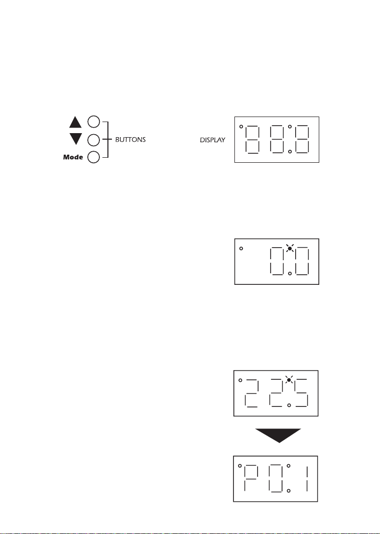
The drive may be programmed by one of three methods: using the three buttons and 3-digit
LED display on the front of the display, programming the Electronic Programming
Module (EPM) using the optional EPM Programmer, and through a serial link using serial
communications. This section describes programming the drive using the buttons and display,
which are shown below:
To enter the PROGRAM mode to access the parameters, press the Mode button. This will
activate the PASSWORD prompt (if the password has not been disabled). The display will read
“00” and the upper right-hand decimal point will be blinking, as shown below:
Press Mode
Display reads “00”
Upper right decimal point blinks
Use the L and M buttons to scroll to the password value (the factory default password is
“225”) and press the Mode button. Once the correct password value is entered, the display
will read “P01”, which indicates that the PROGRAM mode has been accessed at the beginning
of the parameter menu (P01 is the first parameter). This is shown below:
Use L and M to scroll to the
password value
Press Mode to enter password
Parameter menus is accessed at the
first parameter
Page 29
25
NOTE: If the display flashes “Er”, the password was incorrect, and the process to enter the
password must be repeated.
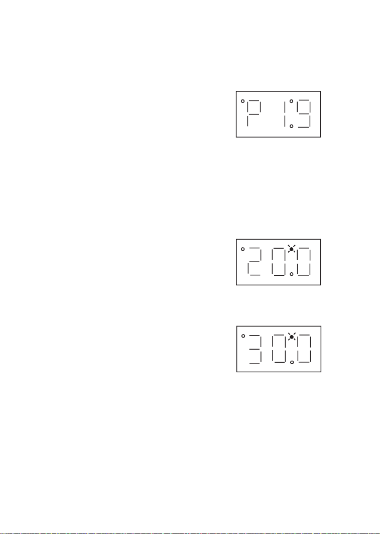
Use the L and M buttons to scroll to the desired parameter number. In the example below,
Parameter 19 is being displayed, which is the ACCELERATION TIME of the drive:
Use L and M to scroll to the desired
parameter number (the example is
Parameter 19 - ACCELERATION
TIME)
Once the desired parameter number is found, press the Mode button to display the present
parameter setting. The upper right-hand decimal point will begin blinking, indicating that the
present parameter setting is being displayed, and that it can be changed by using the L and
M buttons.
Press Mode to display present
parameter setting (example setting
is 20.0)
Upper right decimal point blinks
Use L and M to change setting
(example setting changed to 30.0)
Press Mode to store new setting
Pressing the Mode will store the new setting and also exit the PROGRAM mode. To
change another parameter, press the Mode key again to re-enter the PROGRAM mode (the
parameter menu will be accessed at the parameter that was last viewed or changed before
exiting). If the Mode key is pressed within two minutes of exiting the PROGRAM mode, the
password is not required access the parameters. After two minutes, the password must be
entered in order to access the parameters again.
Page 30
13.1 SETTING VALUES IN TENTHS OF UNITS ABOVE 100
Parameter settings and the keypad speed command can always be adjusted in tenths of unit
increments from 0.0 to 99.9. Above 100 however, values can be set in whole units or tenths
of units, depending on the setting of Parameter 16 - UNITS EDITING.
If Parameter 16 - UNITS EDITING is set to WHOLE UNITS (02), parameter values and the
keypad speed command can only be adjusted by whole unit increments above 100. For example, Parameter 19 - ACCELERATION TIME could not be set to 243.7 seconds. It could only be
set to 243 or 244 seconds. Likewise, the keypad speed command (set using the L and M buttons) could not be set to 113.4 Hz. It could only be set to 113 or 114 Hz.
If, however, Parameter 16 - UNITS EDITING is set to TENTHS OF UNITS (01), parameter values
and the keypad speed command can be adjusted in tenths of unit increments up to a value
of 1000 (above 1000, whole unit increments only). Each push of the L or M button will adjust
the value by one tenth of a unit. If the L or M button is pressed and held, the value will
increment by tenths of units until the next whole unit is reached, and then the value will
increment by whole units.
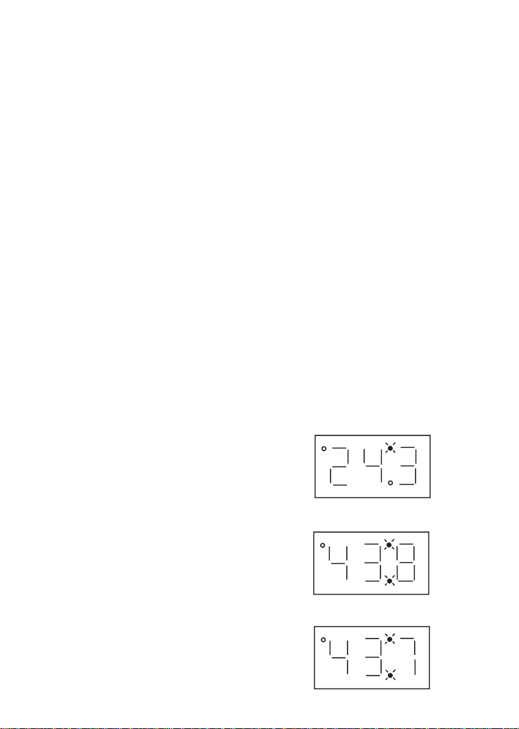
When a value above 100 is being adjusted by tenths of units, the value is shifted to the left by
one digit so that the tenths portion of the value can be displayed. This results in the first digit
(reading from left to right) of the value disappearing from the display. Also, the lower decimal
point will blink to indicate that the actual value is above 100. Once the value is no longer
being adjusted, the value will shift back to the right and the tenths portion of the value will
disappear.
In the example below, Parameter 19 - ACCELERATION TIME is presently set to 243.0 seconds,
and is being increased to 243.7 seconds.
Go to Parameter 19 and press Mode
to see present setting (“243” seconds)
Upper right decimal point blinks
Press L button to see tenths portion
Value shifts to the left (“2” disappears)
Upper right decimal point and lower
decimal point blink
Press L button to scroll up to “43.7”
Press Mode to store new value
26
Page 31

27
13.2 ELECTRONIC PROGRAMMING MODULE (EPM)
Every SpinMaster™ Plus drive has an Electronic Programming Module (EPM) installed on the
main control board. The EPM stores the user’s parameter settings and special OEM default
settings (if programmed). The EPM is removable, allowing it to be installed in another drive for
quick set-up. For example, if a drive is being replaced with a new one, the EPM can be taken
out of the first drive and installed in the new drive. Downtime is minimized because the new
drive does not require programming - it is ready to run when the EPM is installed.
The SpinMaster™ Plus drive contains two or three sets of parameter values, depending on
whether the drive has been programmed with optional OEM default settings. The first set of
values is the factory default settings, which are permanently stored on the main control board
and cannot be changed. The second set of values is the user settings, which are stored in the
EPM. When the drive leaves the factory, the user settings are the same as the factory default
settings, but the user settings can be changed to configure the drive for a particular
application. The optional third set of values is the OEM default settings, which are also stored
in the EPM. OEM default settings are typically used in cases where many drives are used for
the same application, which requires that all of the drives have the same parameter settings.
The OEM default settings cannot be changed without the optional EPM Programmer. The drive
can be programmed to operate according to the user settings or the OEM default settings (see
Parameter 48 in Section 15.0).
NOTE: The drive will not operate without the EPM installed, The drive will display “F1” if the
EPM is missing or damaged.
Do not remove the EPM while power is applied to the drive. Damage to the
EPM and/or drive may result.
An EPM Programmer is available as an option from REGAL-BELOIT CORPORATION, which has
the ability to quickly and easily program many SpinMaster™ Plus drives for the same configuration. Once a “master” EPM is programmed with the desired parameter settings, the EPM
Programmer can copy those setting to other EPMs, allowing many drives to be configured very
quickly. Please consult the EPM Programmer Instruction Manual or contact the factory for mor e
information.
If the OEM settings in the EPM become corrupted, the drive will operate normally, until an
attempt is made to perform a RESET OEM using Parameter 48 - PROGRAM SELECTION. The
drive will then flash “GF” to indicate that the OEM settings are no longer valid. This will requir e
that the EPM be re-programmed using the optional EPM Programmer.
If the OEM settings and the user settings are both corrupted, the drive will display “GF”
immediately and the drive will require a RESET 60 or RESET 50 using Parameter 48 - PROGRAM
SELECTION. Once the RESET is performed, the parameters can then be programmed
individually to match the OEM default settings. This will allow the drive to operate as if it were
in OEM mode, even though it is actually in USER mode. Refer to Parameter 48 in Section 15.0
- DESCRIPTION OF PARAMETERS.
NOTE: The drive will also display “GF” if a RESET OEM or OPERATE WITH OEM SETTINGS is
attempted when the EPM does not contain OEM defaults.
Page 32

28
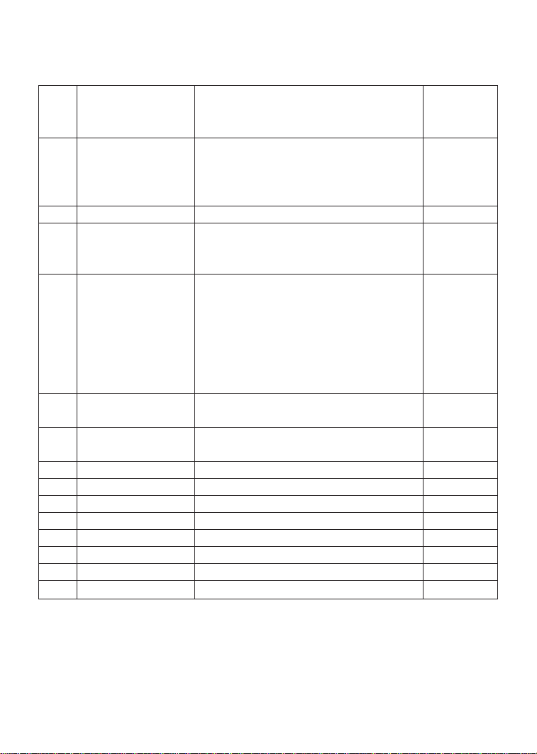
14.0 PARAMETER MENU
FACTORY
NO. PARAMETER NAME RANGE OF ADJUSTMENT DEFAULT
(NOTE 1)
01 LINE VOLTAGE HIGH (01), LOW (02) HIGH (01)
02 CARRIER FREQUENCY 4kHz (01), 6kHz (02), 8kHz (08), 10 kHz (04) 6 kHz (02)
03 START METHOD NORMAL (01), START ON POWER UP (02), NORMAL (01)
START WITH DC BRAKE (03),
AUTO RESTART WITH DC BRAKE (04),
FLYING RESTART 1 (05,) FLYING RESTART 2 (06),
FLYING RESTART 3 (07)
04 STOP METHOD COAST (01), COAST WITH DC BRAKE (02), COAST (01)
RAMP (03), RAMP WITH DC BRAKE (04)
05 STANDARD SPEED KEYPAD (01), PRESET #1 (02), KEYPAD (01)
SOURCE 0-10 VDC (03), 4-20 mA (04)
06 TB-14 OUTPUT NONE (01), RUN (02) ,FAULT (03), NONE (01)
13 TB-15 OUTPUT INVERSE FAULT (04), FAULT LOCKOUT (05), NONE (01)
AT SET SPEED (06), ABOVE PRESET #3 (07),
CURRENT LIMIT (08), AUTO SPEED (09),
REVERSE (10)
08 TB-30 OUTPUT NONE (01), 0-10 VDC FREQ (02), NONE (01)
2-10 VDC FREQ (03), 0-10 VDC LOAD (04),
2-10 VDC LOAD (05)
09 TB-31 OUTPUT NONE (01), 0-10 VDC LOAD (02), NONE (01)
2-10 VDC LOAD (03), DYNAMIC BRAKING (04)
10 TB-13A FUNCTION NONE (01), 0-10 VDC(02), 4-20mA (03), NONE (01)
SELECT PRESET SPEED #1 (04), RUN REVERSE (05),
START REVERSE (06), EXTERNAL FAULT (07),
REMOTE KEYPAD (08), DB FAULT (09),
AUXILIARY STOP (10), ACCEL/DECEL #2 (11)
11 TB-13B FUNCTION NONE (01), 0-10 VDC (02), 4-20mA (03), NONE (01)
SELECT PRESET SPEED #2 (04), DECREASE FREQ (05),
JOG FORWARD (06), JOG REVERSE (07),
AUXILIARY STOP (08)
NOTE 1: Factory defaults are shown for a 60 Hz base frequency. See Parameter 48 for 50
Hz base frequency.
Page 33
29
FACTORY
NO. PARAMETER NAME RANGE OF ADJUSTMENT DEFAULT
(NOTE 1)
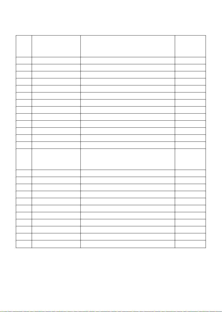
12 TB-13C FUNCTION NONE (01), 0-10 VDC (02), 4-20mA (03), NONE (01)
SELECT PRESET SPEED #3 (04), INCREASE FREQ (05),
EXTERNAL FAULT (06), REMOTE KEYPAD (07),
DB FAULT (08), ACCEL/DECEL #2 (09)
13 TB-15 OUTPUT (SEE PARAMETER 6 - TB-14 OUTPUT) NONE (01)
14 CONTROL TERMINAL STRIP ONLY (01), TERMINAL STRIP
REMOTE KEYPAD ONLY (02), ONLY (01)
TERMINAL STRIP OR REMOTE KEYPAD (03)
15 SERIAL LINK DISABLE (01), 9600, 8, N, 2
9600, 8, N, 2 WITH TIMER (02),
9600, 8, N, 2 WITHOUT TIMER (03),
9600, 8, 3, 1 WITH TIMER (04),
9600, 8, E, 1 WITHOUT TIMER (05),
9600, 8, O, 1 WITH TIMER (06),
9600, 8, O, 1 WITHOUT TIMER (07)
16 UNITS EDITING TENTHS OF UNITS (01), WHOLE
WHOLE UNITS (02) UNITS (02)
17 ROTATION FORWARD ONLY (01), FORWARD
FORWARD AND REVERSE (02) ONLY (01)
19 ACCELERATION TIME 0.1 - 3600.0 SEC 20.0 SEC
20 DECELERATION TIME 0.1 - 3600.0 SEC 20.0 SEC
21 DC BRAKE TIME 0.0 - 3600.0 SEC 0.0 SEC
22 DC BRAKE VOLTAGE 0.0 - 30.0 % 0.0 %
23 MINIMUM FREQUENCY 0.0 - MAXIMUM FREQUENCY 0.0 Hz
24 MAXIMUM FREQUENCY MINIMUM FREQ - 240.0 Hz (NOTE 2) 60.0 Hz
25 CURRENT LIMIT 30 - 180 % (NOTE 3) 180 %
26 MOTOR OVERLOAD 30 - 100 % 100 %
NOTE 1: Factory defaults are shown for a 60 Hz base frequency. See Parameter 48 for 50
Hz base frequency.
NOTE 2: Maximum setting is 999.9 Hz on drives with High Output Frequency option.
Consult the factory.
NOTE 3: If LINE VOLTAGE is set to LOW, maximum setting is 150%.
PARAMETER MENU (cont)
Page 34
30
FACTORY
NO. PARAMETER NAME RANGE OF ADJUSTMENT DEFAULT
(NOTE 1)
27 BASE FREQUENCY 25.0 - 500.0 Hz (NOTE 4) 60.0 Hz
28 FIXED BOOST 0.0 - 30.0 % 1.0 %
29 ACCEL BOOST 0.0 - 20.0 % 0.0 %
30 SLIP COMPENSATION 0.0 - 5.0 % 0.0 %
31-37 PRESET SPEEDS 0.0 - MAXIMUM FREQUENCY 0.0 Hz
38 SKIP BANDWIDTH 0.0 - 10.0 Hz 0.0 Hz
39 SPEED SCALING 0.0 - 6500.0 0.0
40 FREQUENCY SCALING 3.0 -2 000.0 Hz 60.0 Hz
41 LOAD SCALING 10 - 200 % 200 %
42 ACCEL / DECEL #2 0.1 - 3600.0 SEC 20.0 SEC
43 SERIAL ADDRESS 1 - 247 1
44 PASSWORD 000 - 999 225
47 CLEAR HISTORY MAINTAIN (01), CLEAR (02) MAINTAIN (01)
48 PROGRAM USER SETTINGS (01), OEM SETTINGS (02), USER
SELECTION RESET OEM (03), RESET 60 (04), SETTINGS (01)
RESET 50 (05), TRANSLATE (06)
50 FAULT HISTORY (VIEW - ONLY) (N/A)
51 SOFTWARE CODE (VIEW - ONLY) (N/A)
52 DC BUS VOLTAGE (VIEW - ONLY) (N/A)
53 MOTOR VOLTAGE (VIEW - ONLY) (N/A)
54 LOAD (VIEW - ONLY) (N/A)
55 0 - 10 VDC INPUT (VIEW - ONLY) (N/A)
56 4-20 mA INPUT (VIEW - ONLY) (N/A)
57 TB STRIP STATUS (VIEW - ONLY) (N/A)
58 KEYPAD STATUS (VIEW - ONLY) (N/A)
59 TB-30 OUTPUT (VIEW - ONLY) (N/A)
60 TB-31 OUTPUT (VIEW - ONLY) (N/A)
NOTE 1: Factory defaults are shown for a 60 Hz base frequency. See Parameter 48 for 50
Hz base frequency.
NOTE 4: Maximum setting is 1300.0 Hz (factory default is 999.9) on drives with High
Output Frequency option. Consult the factory.
PARAMETER MENU (cont)
Page 35

31
15.0 DESCRIPTION OF PARAMETERS
P01 LINE VOLTAGE SELECTION
This calibrates the drive for the actual applied input voltage, and can be set to HIGH (01) or
LOW (02). Refer to the table below for the proper setting depending on the input voltage.
RATED INPUT INPUT APPLIED INPUT PARAMETER
MODELS VOLTAGE PHASE VOLTAGE SETTING
T310 - 208 / 240 Vac 1 or 3 220 - 240 Vac HIGH (01)
T318 1 or 3 220 - 203 Vac LOW (02)
T324 - 208 / 240 Vac 3 220 - 240 Vac HIGH (01)
T331, T333 3 200 - 208 Vac LOW (02)
T332, 400 / 480 Vac 3 440 - 480 Vac HIGH (01)
T334 - T344 3 380 - 415 Vac LOW (02)
T354 - 480 / 590 Vac 3 575 - 600 Vac HIGH (01)
T363 3 460 - 480 Vac LOW (02)
NOTE: If this parameter is changed while the drive is running, the new value will not take
effect until the drive is stopped.
P02 CARRIER FREQUENCY
This sets the switching rate of the output IGBT’s. Increasing the carrier frequency will result in
less audible motor noise. Available settings are: 4 kHz, 6 kHz, 8 kHz, and 10 kHz.
PARAMETER CARRIER MAXIMUM OUTPUT AMBIENT OR OUTPUT
SETTING FREQUENCY FREQUENCY (NOTE 1) DERATE (NOTE 2)
01 4 kHz 240.0 Hz (400.0 Hz) 50 C or 100 %
02 6 kHz 240.0 Hz (600.0 Hz) 50 C or 100 %
03 8 kHz 240.0 Hz (999.9 Hz) 43 C or 92 %
04 10 kHz 240.0 Hz (999.9 Hz) 35 C or 82 %
NOTE 1: For drives with the High Output Frequency option, the carrier frequency also
determines the maximum output frequency (shown in parenthesis).
NOTE 2: The SpinMaster™ Plus drive is fully rated up to 6 kHz carrier frequency. If the 8 kHz
or 10 kHz carrier frequency is selected, the drive’s ambient temperature rating OR output
current rating must be derated to the value shown in the table above.
Page 36

NOTE 3: If this parameter is changed while the drive is running, the change will not take
effect until the drive is stopped. Therefore, the allowable maximum frequency for drives with
the High Output Frequency option (see NOTE 1) will not change if the carrier frequency is
changed while the drive is running.
P03 START METHOD
Automatic starting of equipment may cause damage to equipment and / or
injury to personnel! Automatic start should only be used on equipment that is inaccessible to
personnel.
01 NORMAL: The drive will start when the appropriate contact is closed on the terminal
strip, or by pressing the START key on the optional remote keypad. See Parameter 14.
02 START ON POWER UP: The drive will automatically start upon application of input
power.
03 START WITH DC BRAKE: When a START command is given, the drive will apply DC
BRAKE VOLTAGE (Parameter 22) for the duration of DC BRAKE TIME (Parameter 21)
prior to starting the motor to ensure that the motor is not turning.
04 AUTO RESTART WITH DC BRAKING: Upon a START command, after a fault, or upon
application of power, the drive will apply DC BRAKE VOLTAGE (Parameter 22) for the
duration of DC BRAKE TIME (Parameter 21) prior to starting (or restarting) the motor.
05 FLYING RESTART 1: LOW performance. Slowest synchronization and lowest current
level. This setting results in the smoothest synchronization.
06 FLYING RESTART 2: MEDIUM performance. Faster synchronization and higher current
level. This setting allows faster synchronization while retaining smoothness.
07 FLYING RESTART 3: HIGH performance. Fastest synchronization and highest current
level. This setting allows the fastest synchronization, but sacrifices smoothness.
The FLYING RESTART 1 - 3 settings allow the drive to start into a spinning load after a fault or
upon application of input power. They differ in the time required to find the motor and the
amount of current required to synchronize with it. The faster the drive attempts to find the
motor, the more current is required.
When programmed for auto-restart, the drive will attempt three restarts after a fault. The
interval between restart attempts is 15 seconds for setting 04, and 2 seconds for settings 05,
06 and 07. During the interval between restart attempts, the display will read “SP” to indicate
Start Pending. If all three restart attempts fail, the drive will trip into FAULT LOCKOUT (displayed
“LC”) and require a manual reset. Refer to Section 16.0 - TROUBLESHOOTING.
NOTE: Settings 02 and 04 - 07 require a two-wire start/stop circuit to operate. The RUN
contact must remain closed for the power-up start and auto-restart functions to operate.
32
Page 37

33
P04 STOP METHOD
01 COAST TO STOP: When a STOP command is given, the drive shuts off the output to
the motor, allowing it to coast freely to a stop.
02 COAST WITH DC BRAKE: When a stop command is given, the drive will activate DC
braking (after a delay of up to 2 seconds, depending on frequency) to help decelerate
the load. Refer to Parameters: 21 - DC BRAKE TIME, and 22 - DC BRAKE VOLTAGE.
03 RAMP TO STOP: When a stop command is given, the drive will decelerate the motor
to a stop at the rate determined by Parameter 20 - DECELERATION TIME.
04 RAMP WITH DC BRAKE: When a stop command is given, the drive will decelerate the
motor down to 0.2 Hz (at the rate set by Parameter 20 - DECELERATION TIME) and
then activate DC braking according to the settings of Parameters 21 - DC BRAKE TIME
and 22 - DC BRAKE VOLTAGE. This is used to bring the load to a final stop, as the motor
may still be turning slightly after the drive stops.
P05 STANDARD SPEED SOURCE
This selects the speed reference source when the drive is in STANDARD speed mode. The
following speed reference can be selected.
01 KEYPAD: Use the L and M buttons to scroll to the desired speed.
02 PRESET SPEED #1: The drive will operate at the frequency set into Parameter 31.
03 0 - 10 VDC: The drive will respond to a 0 - 10 VDC signal wired to TB-2 and TB-5.
04 4 - 20 mA: The drive will respond to a 4-20 mA signal wired to TB-2 and TB-25.
P06 TB-14 OPEN COLLECTOR OUTPUT
This selects the status indication for the open-collector output at TB-14. The terms “open” and
“close” refer to the state of the internal transistor that activates the circuit. When the transistor
is “closed”, TB-14 is at the same potential as TB-2, allowing current to flow.
01 NONE: Disables the open-collector output.
02 RUN: Closes upon a START command. Opens if the drive is in a STOP state, the drive
faults, or input power is removed. DC braking is considered a STOP state.
03 FAULT: Closes if there is no fault condition. Opens if the drive faults, or input power is
removed.
04 INVERSE FAULT: Closes is the drive faults. Opens if there is no fault condition.
05 FAULT LOCKOUT: Closes when input power is applied. Opens if three restart attempts
are unsuccessful, or if input power is removed.
Page 38

34
06 AT SET SPEED: Closes if the drive is within ± 0.5 Hz of the speed setpoint.
07 ABOVE PRESET SPEED #3: Closes if the output frequency exceeds the PRESET SPEED
#3 setting. Opens if the output frequency is equal to or less than PRESET SPEED #3
(Parameter 33).
08 CURRENT LIMIT : Closes if the output curr ent exceeds the CURRENT LIMIT setting. Opens
if the output current is equal to or less than CURRENT LIMIT (see Parameter 25).
09 AUTOMATIC SPEED MODE: Closes if an AUTOMATIC (terminal strip) speed reference is
active. Opens if a STANDARD (Parameter 5) speed reference is active.
10 REVERSE: Closes when reverse rotation is active. Opens when forward rotation is
active. (see Parameter 17 - ROTATION DIRECTION).
P08 TB-30 ANALOG OUTPUT
Terminal TB-30 can be used as an analog output proportional to either output frequency or
load. FREQUENCY SCALING (Parameter 40) or LOAD SCALING (Parameter 41) can be used to
scale the output signal.
01 NONE
02 0-10 VDC FREQ
03 2-10 VDC FREQ
04 0-10 VDC LOAD
05 2-10 VDC LOAD
NOTE: The 2-10 VDC signal can be converted to a 4-20 mA signal by connecting a resistor
in series with the signal such that the total load resistance is 500 Ohms. However, this output
cannot be used with devices that derive power from a 4-20 mA signal.
P09 TB-31 ANALOG OUTPUT
Terminal TB-31 can be used as an analog output proportional to load, or as the control signal
to activate the optional external Dynamic Braking module. LOAD SCALING (Parameter 41) can
be used to scale the output signal when TB-31 is used as an analog output proportional to
load.
01 NONE
02 0-10 VDC LOAD
03 2-10 VDC LOAD
04 DYNAMIC BRAKING: TB-31 becomes the “trigger” that activates the optional external
Dynamic Braking module. Refer to the instructions included with the Dynamic Braking
option.
NOTE: The 2-10 VDC signal can be converted to a 4-20 mA signal by connecting a resistor
in series with the signal such that the total load resistance is 500 Ohms. However, this output
cannot be used with devices that derive power from a 4-20 mA signal.
Page 39

P10 TB-13A FUNCTION SELECT
This selects the function of terminal TB-13A. Closing TB-13A to TB-2 (or opening in the case of
settings 7 and 10) activates the selected function. The following functions can be selected:
01 NONE: Disables the TB-13A function.
02 0-10 VDC: Selects a 0-10 VDC signal (at TB-5) as the AUTO speed reference input.
03 4-20 mA: Selects a 4-20 mA signal (at TB-25) as the AUTO speed reference input.
04 PRESET SPEED #1: Selects PRESET SPEED #1 as the AUTO speed reference. The drive
will operate at the frequency programmed into Parameter 31.
05 RUN REVERSE: Close TB-13A to TB-2 to RUN in the reverse direction, and open to STOP.
This setting forces TB-12 to act as RUN FWD, requiring a maintained contact to RUN in
the forward direction. TB-1 must be closed to TB-2 for this function to operate.
06 START REVERSE: Momentarily close TB-13A to TB-2 to START the drive in the reverse
direction. Momentarily open TB-1 to TB-2 to STOP. This setting forces TB-12 to act as
START FWD, requiring a momentary contact to START in the forward direction.
07 EXTERNAL FAULT: Sets TB-13A as a normally closed external fault input. If TB-13A is
open with respect to TB-2, the drive will fault.
08 REMOTE KEYPAD: Selects the optional remote keypad as the control source. Refer to
Parameter 14 - CONTROL.
09 DB FAULT: Sets TB-13A as a dynamic braking fault input when using the optional
dynamic braking module. When this input is activated by the dynamic braking
module, the drive will trip into a “dF” fault and the motor will coast to a stop. Refer to
the manual included with the Dynamic Braking option.
10 AUXILIARY STOP: When TB-13A is opened with respect to TB-2, the drive will decelerate
to a STOP (even if STOP METHOD is set to COAST) at the rate set into Parameter 42 -
ACCEL/DECEL #2.
11 ACCEL/DECEL #2: Selects the acceleration and deceleration time programmed into
Parameter 42 - ACCEL/DECEL #2.
NOTE: In order for the RUN REVERSE and START REVERSE function to operate, Parameter 17
- ROTATION DIRECTION must be set to FORWARD AND REVERSE (02).
P11 TB-13B FUNCTION SELECT
This selects the function of terminal TB-13B. Closing TB-13B to TB-2 (or opening in the case of
setting 08) activates the selected function. The following functions can be selected:
35
Page 40
01 NONE: Disables the TB-13B function.
02 0-10 VDC: Selects a 0-10 VDC signal (at TB-5) as the AUTO speed reference input.
03 4-20 mA: Selects a 4-20 mA signal (at TB-25) as the AUTO speed reference input.
04 PRESET SPEED #2: Selects PRESET SPEED #2 as the AUTO speed reference. The drive
will operate at the frequency programmed into Parameter 32.
05 DECREASE FREQUENCY: Decreases the speed setpoint when using the MOP function.
Refer to Section 10.6.
06 JOG FORWARD: Jog in the forward direction. In this mode, the drive will JOG at the
speed programmed into Parameter 32 - PRESET SPEED #2.
07 JOG REVERSE - Jog in the reverse direction. In this mode, the drive will JOG at the
speed programmed into Parameter 32 - PRESET SPEED #2.
When operating in JOG mode, the STOP terminal (TB-1), the AUXILIARY STOP
function (see setting 08), and the STOP key on the optional remote keypad WILL NOT stop the
drive. To stop the drive, remove the JOG command.
JOG REVERSE will operate the drive in reverse even if ROTATION DIRECTION
(Parameter 17) is set to FORWARD ONLY.
08 AUXILIARY STOP: When TB-13B is opened with respect to TB-2, the drive will decelerate
to a STOP (even if STOP METHOD is set to COAST) at the rate set into Parameter 42 ACCEL/DECEL #2.
NOTE: If the drive is commanded to JOG when running, the drive will enter JOG mode and
run at PRESET SPEED #2. When the JOG command is removed, the drive will STOP.
P12 TB-13C FUNCTION SELECT
This selects the function of terminal TB-13C. Closing TB-13C to TB-2 (or opening in the case of
setting 06) activates the selected function. The following functions can be selected:
01 NONE: Disables the TB-13C function.
02 0-10 VDC: Selects a 0-10 VDC signal (at TB-5) as the AUTO speed reference input.
03 4-20 mA: Selects a 4-20 mA signal (at TB-25) as the AUTO speed reference input.
04 PRESET SPEED #3: Selects PRESET SPEED #3 as the AUTO speed reference. The drive
will operate at the frequency programmed into Parameter 33.
05 INCREASE FREQUENCY: Increases the speed setpoint when using the MOP function.
Refer to Section 10.6.
36
Page 41

06 EXTERNAL FAULT: Sets TB-13C as a normally closed external fault input. If TB-13C is
open with respect to TB-2, the drive will fault.
07 REMOTE KEYPAD: Selects the optional remote keypad as the control source. Refer to
Parameter 14 - CONTROL.
08 DB FAULT: Sets TB-13C as a dynamic braking fault input when using the optional
dynamic braking module. When this input is activated by the dynamic braking
module, the drive will trip into a “dF” fault and the motor will coast to a stop. Refer to
the manual included with the Dynamic Braking option.
09 ACCEL/DECEL #2: Selects the acceleration and deceleration time programmed into
Parameter 42 - ACCEL/DECEL #2.
P13 TB-15 OPEN COLLECTOR OUTPUT
This selects the status indication for the open-collector output at TB-15, and has the same
selections as Parameter 6 - TB-14 OPEN COLLECTOR OUTPUT.
P14 CONTROL
This selects the source of START/STOP and direction commands.
01 TERMINAL STRIP ONLY: The drive will only respond to START/STOP and direction
commands from the terminal strip.
02 REMOTE KEYPAD ONLY: The drive will only respond to START/STOP and direction
commands from the optional remote keypad.
03 TERMINAL STRIP OR REMOTE KEYPAD: Terminal TB-13A or TB-13C can be used to select
terminal strip control or remote keypad control. See Parameters 10 and 12.
NOTE: This STOP button on the optional remote keypad is always active as long as the serial
link remains intact.
P15 SERIAL LINK
This parameter configures the drive for serial communications. The options are listed by baud
rate, number of data bits, parity, number of stop bits, and whether the watchdog timer is
enabled or disabled.
The watchdog timer will stop the drive after 10 seconds of no serial activity to safeguard
against a failed serial link. During set-up or troubleshooting, it may be useful to disable the
watchdog timer, but it is not recommended to run normally without the watchdog timer.
Controlling the drive from the serial link without the watchdog timer could
cause damage to equipment and/or injury to personnel!
37
Page 42

01 DISABLED: Disables the serial link
02 9600, 8, N, 2- ENABLED WITH TIMER
03 9600, 8, N, 2- ENABLED WITHOUT TIMER
04 9600, 8, E, 1 - ENABLED WITH TIMER
05 9600,8,E,1 - ENABLED WITHOUT TIMER
06 9600, 8, O, 1 - ENABLED WITH TIMER
07 9600, 8, O, 1 - ENABLED WITHOUT TIMER
P16 UNITS EDITING
This allows parameter and keypad speed editing in whole units or tenths of units above 100.
Below 100, the value can always be changed by tenths of units.
01 TENTHS OF UNITS: The value can always be changed by tenths of units (up to a value
of 1000). If the L or M button is pressed and held, the value will change by tenths of
units until the next whole unit is reached, and then the value will change by whole
units. Refer to Section 13.1.
02 WHOLE UNITS: The value can be changed by tenths of units until 99.9 is reached.
Above 99.9, the value will change in whole unit increments only. Below a value of
100, if the L or M button is pressed and held, the value will change by tenths of units
until the next whole unit is reached, and then the value will change by whole units.
P17 ROTATION DIRECTION
01 FORWARD ONLY: The drive will only allow rotation in the forward direction. However,
JOG REVERSE (see Parameter 11) will still operate even if FORWARD ONLY is selected.
02 FORWARD AND REVERSE: The drive will allow rotation in both directions.
P19 ACCELERATION TIME
This parameter sets the acceleration rate for all of the speed reference sources (keypad, speed
pot, 4-20 mA, 0-10 VDC, jog, MOP, and preset speeds). This setting is the time to accelerate
from 0 Hz to the BASE FREQUENCY (Parameter 27).
P20 DECELERATION TIME
This parameter sets the deceleration rate for all of the speed reference sources (keypad, speed
pot, 4-20 mA, 0-10 VDC, jog MOP, and preset speeds). This setting is the time to decelerate
from BASE FREQUENCY to 0 Hz.. If the drive is set for COAST TO STOP (setting 01 or 02 in
Parameter 04), this parameter will have no effect when a STOP command is given.
P21 DC BRAKE TIME
This determines the length of time that the DC braking voltage is applied to the motor. The DC
BRAKE TIME should be set to the lowest value that provides satisfactory operation in order to
minimize motor heating.
38
Page 43

39
P22 DC BRAKE VOLTAGE
This sets the magnitude of the DC braking voltage, in percentage of the nominal DC Bus
voltage (DC Bus = input AC voltage X 1.414). The point at which the DC braking is activated
depends on the selected STOP METHOD (Parameter 04):
IF COAST WITH DC BRAKE is selected, the DC braking is activated after a time delay of up to 2
seconds, depending on the output frequency at the time of the STOP command. In this case,
the DC braking is the only force acting to decelerate the load.
IF RAMP WITH DC BRAKE is selected, braking is activated when the output frequency reaches
0.2 Hz. In this case, the drive decelerates the load to a near stop and the DC braking is used
to bring the load to a final stop.
P23 MINIMUM FREQUENCY
This sets the minimum output frequency of the drive for all speed refer ence sources except the
PRESET SPEEDS (Parameters 31-37).
When using a 0-10 VDC or 4-20 mA analog speed reference signal, this parameter also sets
the drive speed that corresponds to the minimum analog input (0 VDC or 4 mA).
NOTE: If this parameter is changed while the drive is running, the new value will not take
effect until the drive is stopped.
P24 MAXIMUM FREQUENCY
This sets the maximum output frequency of the drive for all speed reference sources, and is
used with MINIMUM FREQUENCY (Parameter 23) to define the operating range of the drive.
When using a 0-10 VDC or 4-20 mA analog speed reference signal, this parameter also sets
the drive speed that corresponds to the maximum analog input (10 VDC or 20 mA).
NOTE 1: On drives equipped with the High Output Frequency option, this parameter can be
set up to 999.9 Hz.
NOTE 2: If this parameter is changed while the drive is running, the new value will not take
effect until the drive is stopped.
P25 CURRENT LIMIT
This sets the maximum allowable output current of the drive. The maximum setting is either
180% or 150%, depending on whether LINE VOLTAGE SELECTION (Parameter 01) is set to
HIGH or LOW.
The drive will enter current limit when the load demands more current than the CURRENT
LIMIT setting. When this happens, the drive will reduce the output frequency in an attempt to
reduce the output current. When the overload condition passes, the drive will accelerate the
motor back up to the speed setpoint.
Page 44
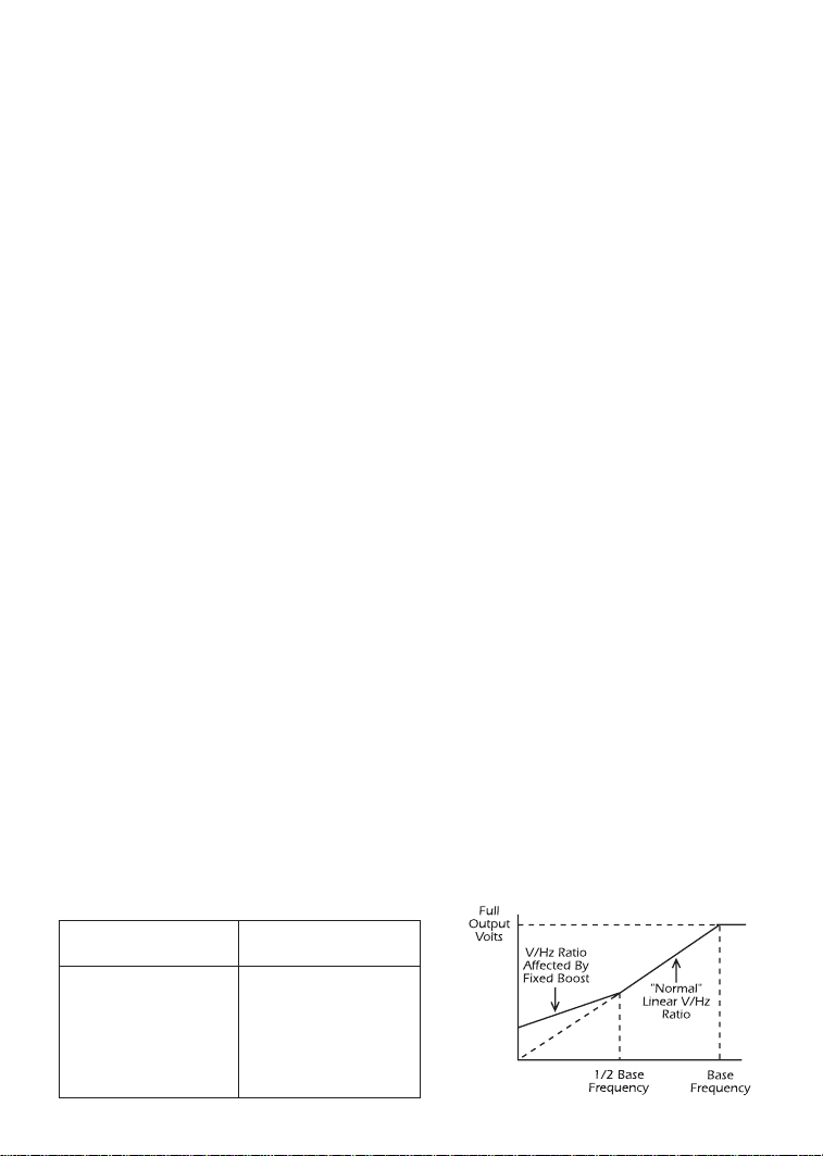
40
P26 MOTOR OVERLOAD
The SpinMaster™ Plus is UL approved for solid state motor overload protection, and therefore
does not require a separate thermal overload relay for single motor applications.
The drive contains an adjustable thermal overload circuit that protects the motor from excessive
overcurrent. This circuit allows the drive to deliver up to 150% current for one minute. If the
overload circuit “times out”, the drive will trip into an OVERLOAD fault (displayed as “PF”).
MOTOR OVERLOAD should be set to the ratio (in percent) of the motor current rating to the
drive current rating in order to properly protect the motor. See the example below.
Example: A 3 HP, 480 Vac drive with a 4.8 Amp rating is operating a 2 HP motor with a
current rating of 3.4 Amps. Dividing the motor current rating by the drive current rating yields
71% (3.4 / 4.8 = 0.71 = 71%), so this parameter should be set to 71%.
P27 BASE FREQUENCY
The BASE FREQUENCY determines the V/Hz ratio by setting the output frequency at which the
drive will output full voltage to the motor. In most cases, the BASE FREQUENCY should be set
to match the motor’s rated frequency.
Example: A 460 Vac, 60 Hz motor requires a V/Hz ratio of 7.67 (460 V / 60 Hz = 7.67 V/Hz)
to produce full torque. Setting the BASE FREQUENCY to 60 Hz causes the drive to output
full voltage (460 Vac) at 60 Hz, which yields the required 7.67 V/Hz. Output voltage is
proportional to output frequency, so the 7.67 V/Hz ratio is maintained from 0 - 60 Hz,
allowing the motor to produce full torque from 2 Hz (below 2 Hz there is less torque due to
slip) up to 60 Hz.
NOTE: If this parameter is changed while the drive is running, the new value will not take
effect until the drive is stopped.
P28 FIXED BOOST
FIXED BOOST increases starting torque by increasing the output voltage when operating
below half of the base frequency, which increases the V/Hz ratio (see diagram below). For
better out-of-the-box performance, SpinMaster™ Plus drives are shipped with a setting that is
different from the factory default, as seen in the table below. If a factory reset is performed,
FIXED BOOST will default to 1.0%.
FACTORY FACTORY
HP SETTING HP SETTING
0.25 -1 5.3 % 7.5 2.7 %
1.5 4.4 % 10 2.4 %
2 4.4 % 15 2.2 %
3 3.6 % 20 2.0 %
5 3.0 % 25 1.8 %
Page 45

P29 ACCELERATION BOOST
ACCELERATION BOOST helps accelerate high-inertia loads. During acceleration, the output
voltage is increased to increase motor torque. Once the motor reaches the new speed
setpoint, the boost is turned off and the output voltage returns to the normal value.
P30 SLIP COMPENSATION
SLIP COMPENSATION is used to counteract changes in motor speed (slip) caused by changes
in load. In a standard AC induction motor, the shaft speed decreases as load increases, and
increases as load decreases. By increasing or decreasing the output frequency in response to
an increasing or decreasing load, the slip is counteracted and speed is maintained. Most
standard NEMA B motors have a 3% slip rating.
P31 - P37 PRESET SPEED #1 - #7
Preset speeds are activated by contact closures between TB-2 and TB-13A, 13B, and 13C. The
TB-13 terminals must be programmed as preset speed selects using Parameters 10-12.
NOTE 1: Preset speeds can operate below the frequency defined by the minimum
frequency parameter (Parameter 23). The range of adjustment for the preset speeds is from 0
Hz to the maximum frequency (Parameter 24).
Refer to the table below for activation of the preset speeds using the TB-13 terminals.
NOTE 2: When a TB-13 terminal is programmed for a function other than a preset speed
select, it is considered OPEN for the table above.
Preset Speed #6 and #7 can also be used as skip frequencies to restrict the drive from
operating at frequencies that cause vibration in the system. See Parameter 38 below.
P38 SKIP BANDWIDTH
The SpinMaster™ Plus drive has two skip frequencies that can be used to lock out critical
frequencies that cause mechanical resonance in the system. Once SKIP BANDWIDTH is set to
a value other than 0.0 Hz, the skip frequencies are enabled. When the skip fr equency function
is enabled, PRESET SPEED #6 and #7 are used as the skip frequencies. SKIP BANDWIDTH sets
the range above the skip frequencies that the drive will not operate within.
41
SPEED # TB-13A TB-13B TB-13C
1 CLOSED OPEN OPEN
2 OPEN CLOSED OPEN
3 OPEN OPEN CLOSED
4 CLOSED CLOSED OPEN
5 CLOSED OPEN CLOSED
6 OPEN CLOSED CLOSED
7 CLOSED CLOSED CLOSED
Page 46

42
Example: The critical frequency is 23 Hz, and it is desired to skip a frequency range of 3 Hz
above and below the critical frequency (therefor e the skip range is 20 to 26 Hz). PRESET SPEED
#6 or #7 would be set to 20 Hz, and the SKIP BANDWIDTH would be set to 6.0 Hz.
If the drive is running at a speed below the skip range, and it is given a speed command that
is within the skip range, the drive will accelerate to the start of the skip range (20 Hz in the
example) and run at the speed until the speed command is greater than or equal to the “top”
of the skip range. The drive will then accelerate through the skip range to the new speed.
Likewise, if the drive is running at a speed above the skip range, and it is given a speed
command that is within the skip range, the drive will decelerate to the “top” of the skip range
(26 Hz in the example) and run at that speed until the speed command is less than or equal
to the “bottom” of the skip range. The drive will then decelerate through the skip range to the
new speed.
NOTE: PRESET SPEEDS #6 and #7 can still be used as preset speeds even if they are also being
used as skip frequencies.
P39 SPEED SCALING
This scales the display to indicate speed or user units other than frequency. This parameter
should be set to the desired display value when the drive output is 60 Hz. The highest setting
is 6500, and the highest value that can be displayed is 6553.6.
Example: A machine produces 175 parts per hour when the motor is running at 60 Hz.
Setting the SPEED SCALING to 175 will calibrate the drive’ s display to r ead 175 when the motor
is running at 60 Hz. This is a linear function, so at 30 Hz the display would read 87.5, and at
120 Hz, the display would read 350.
NOTE: If SPEED SCALING is set such that the maximum displayable value (6553.6) is
exceeded, the display will flash “9999” to indicate that the value is out of range. For example,
if SPEED SCALING is set to 6000, the drive will display 6000 when it is running at 60 Hz. If the
speed is increased past 65.5 Hz (at 65.5 Hz, the scaled value would be 6550), the display will
flash “9999” because a scaled value above 6553.6 cannot be displayed.
P40 FREQUENCY SCALING
This scales the analog output signal at TB-30 when it is configured for a frequency output. This
setting is the output frequency that is indicated when the output signal measures 10 VDC.
Example: A 0-5 VDC signal is required to indicate 0-60 Hz. Setting this parameter to 120 Hz
would yield 10 VDC at 120 Hz, and 5 VDC at 60 Hz. If the drive only operates up to 60 Hz,
the output signal at TB-30 is limited to the desired 0-5 VDC.
P41 LOAD SCALING
This scales the analog output signal at TB-30 and /or TB-31 when they are configured for a
load output. This setting is the load (in %) that is indicated when the output signal measures
10 VDC.
Page 47

43
Example: A 0-10 VDC signal is required to indicate 0-150% load. Setting this parameter to
150% will yield 10 VDC at 150% load.
P42 ACCEL / DECEL #2
This parameter sets the second acceleration and deceleration rate of the drive. To activate this
acceleration and deceleration rate, use terminal TB-13A, TB-13B or TB-13C. TB-13A and TB-13B
can be set to AUXILIARY STOP which will cause the drive to decelerate to a stop according to
the time programmed in this parameter. TB-13C can be set to ACCEL/DECEL #2, which
causes the drive to accelerate and decelerate according to the time programmed in this
parameter.
P43 SERIAL ADDRESS
If a serial link is being used to communicate with multiple drives, each drive must be given a
different address (from 1 to 247) so that an individual drive in the network can be accessed.
P44 PASSWORD
This allows the PASSWORD to be changed to any number between 000 and 999. Setting
PASSWORD to 000 disables the password function.
NOTE: The factory default password is 225.
P47 CLEAR FAULT HISTORY
01 MAINTAIN: Maintains the FAULT HISTORY (Parameter 50) entries for troubleshooting.
02 CLEAR: Erases the FAULT HISTORY (Parameter 50) entries.
P48 PROGRAM SELECTION
This is used to select whether the drive will operate according to the user settings or the
optional OEM default settings, and to reset the parameters to default settings. Refer to Section
13.2.
01 OPERATE WITH USER SETTINGS: The drive will operate according to the users settings.
Operation in USER mode allows the parameter values to be changed to suit any
application.
02 OPERATE WITH OEM DEFAULTS: The drive will operate according to the optional OEM
default settings, which configure the drive for a specific application. When operating
in OEM mode, the parameter values can be viewed, but not changed. If an attempt is
made to change a parameter setting, the display will flash “GE”. If the drive is not
programmed with OEM default settings, the display will flash “GF” if this option is
selected.
Page 48

03 RESET OEM: Resets the user parameters to the OEM default settings. If the drive is not
programmed with OEM default settings, the display will flash “GF” if this option is
selected.
04 RESET 60: Resets the users parameters to the factory defaults for a 60 Hz base
frequency.
05 RESET 50: Resets the user parameters to the factory defaults for a 50 Hz base
frequency. Parameters 24, 27, and 40 will reset to 50.0 Hz.
06 TRANSLATE: If an EPM from a drive with a previous parameter version is installed in a
new drive, the new drive will function like the previous version drive, but none of the
parameter settings can be changed (“cE” will be displayed if this is attempted). The
TRANSLATE function converts the EPM to the new parameter version so that the
parameters can be changed, but it also retains the old parameter settings so the new
dive will operate like the old drive without having to re-program all of the parameters.
NOTE 1: If the user parameters are reset to the OEM defaults (using the RESET OEM option),
and then OPERATE WITH USER SETTINGS is selected, the USER settings will be the same as the
OEM default settings. This allows the drive to operate as if it was in OEM mode, but the
parameter values can be changed. This is useful if some of the OEM default settings need to
be fine-tuned for proper operation. The new parameter values are not actually stored as new
OEM default settings however, they are simply stored as new USER settings. Therefore, if the
parameters are reset to the OEM defaults again, the parameters that were changed will be
reset to their “old” value. The optional EPM Programmer is required to change OEM default
settings. Refer to Section 13.2.
NOTE 2: Only the TRANSLATE (06) function can be performed while the drive is running.
The display will flash “Er” if an attempt is made to select any other function while the drive is
running.
P50 FAULT HISTORY
The FAULT HISTORY stores the last eight faults that tripped the drive. Refer to Section 16.0 TROUBLESHOOTING for a list of the faults and possible causes.
Use the L and M buttons to scroll through the fault entries. The far left digit of the display will
be the fault number and the remaining two digits will be the fault code. The faults are stored
from newest to oldest, with the first fault shown being the most recent.
The display will read “_ _” if the FAULT HISTORY does not contain any fault messages.
P51 SOFTWARE VERSION
This displays the software version number for the control board software. This information is
useful when contacting the factory for programming or troubleshooting assistance.
44
Page 49
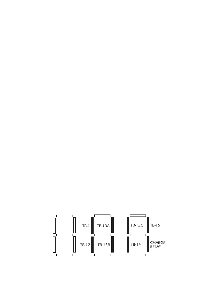
The software version is displayed in two parts which alternate. The first part is the software
version, and the second part is the revision number. For example, if the display shows “64-”
and “-02”, this indicates that the drive contains the second revision of version 64 software.
P52 DC BUS VOLTAGE
This displays the DC bus voltage in percent of nominal. Nominal DC bus voltage is determined
by multiplying the drive’s nameplate input voltage rating by 1.4.
P53 MOTOR VOLTAGE
This displays the output voltage in percent of the drive’s nameplate output voltage rating.
P54 MOTOR LOAD
This displays the motor load in percent of the drive’s output current rating.
P55 0-10 VDC ANALOG INPUT
This displays the level of the 0-10 VDC analog input signal at TB-5. A reading of 100%
indicates a 10 VDC input at TB-5.
P56 4-20 mA ANALOG INPUT
This displays the level of the 4-20 mA analog input signal at TB-25. A reading of 20% indicates
a 4 mA input at TB-25, and a reading of 100% indicates a 20 mA input at TB-25.
P57 TERMINAL STRIP STATUS
This indicates that status of several terminals using the vertical segments of the LED display. An
illuminated segment indicates that the particular terminal is closed with respect to TB-2. The
CHARGE RELAY is not a terminal, and should always be illuminated. See the diagram below:
45
Page 50
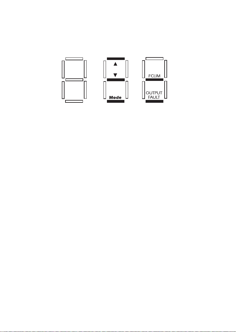
P58 KEYPAD AND PROTECTION STATUS
This indicates the status of the buttons on the keypad, and the status of the protective
circuitry in the drive, using the horizontal segments of the LED. An illuminated segment
indicates that the corresponding button is pressed, or the protective circuit is active. See the
diagram below:
NOTE: FCLIM is an abbreviation for Fast Current Limit.
P59-P60 TB-30 and TB-31 ANALOG OUTPUT
This displays the level of the analog output signals at TB-30 (Parameter 59) and TB-31
(Parameter 60). A reading of 100% indicates that the output is 10 VDC.
46
Page 51
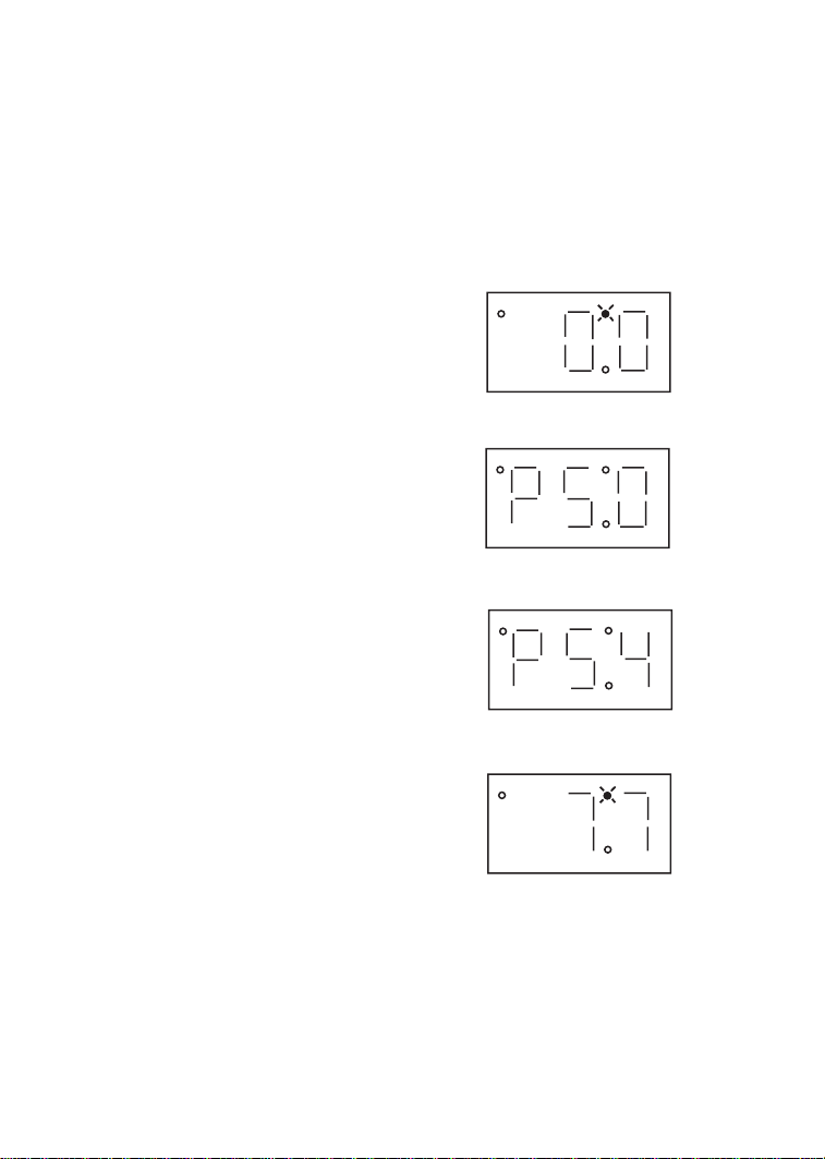
16.0 TROUBLESHOOTING
To aid in troubleshooting, Parameters 50 through 60 can be accessed without entering the
PASSWORD. Simply press the Mode button twice to “skip” over the PASSWORD prompt, and
“P50” will be displayed to indicate that the parameter menu has been entered and Parameter
50 (FAULT HISTORY) can be viewed. The L and M buttons can be used to scroll from
Parameter 50 to Parameter 60. Once the desired parameter is found, press the Mode button
to view its “contents”. When finished, press Mode to exit the parameter menu. An example is
shown below:
Press Mode once
Display reads “00”
Upper right decimal point blinks
Press Mode again
Display reads “P50” (FAULT HISTORY)
Use L and M to scroll to the desired
parameter number
(In this example Parameter 54 has been
selected, which is MOTOR LOAD)
Press Mode to view parameter contents
(77 = 77% LOAD)
Upper right decimal point blinks
Press Mode again to exit
In the example above, Parameter 54 - MOTOR LOAD is being viewed. The “77” in the
example indicates that the load on the motor is 77% of the output current rating of the drive.
47
Page 52
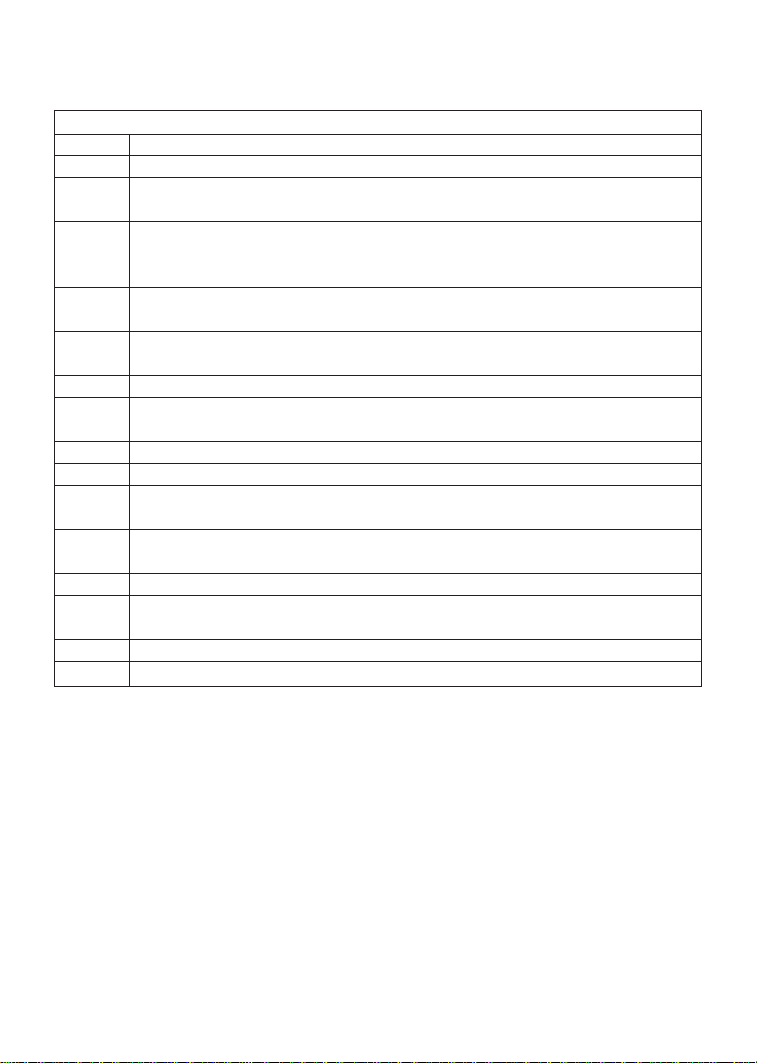
The table below lists the fault conditions that will cause the drive to shut down, as well as some
possible causes. Please contact the factory for more information on troubleshooting faults.
To clear a fault, issue a STOP command, either on the terminal strip, or using the STOP button
on the optional remote keypad. The fault will only clear if the condition that caused the fault
has passed. For example, if the drive trips on a LOW DC BUS VOLTAGE FAULT (LF) due to low
input voltage, the fault cannot be cleared until the input voltage returns to a normal level.
If the drive is programmed to automatically restart after a fault (see Parameter 03), the drive
will attempt to restart three times after a fault (the drive will not restart after CF, cF, GF, F1, F2F9, or Fo faults). If all three restart attempts are unsuccessful, the drive will trip into FAULT
LOCKOUT (LC), which requires a manual reset as described above.
48
FAULT MESSAGES
FAULT DESCRIPTION & POSSIBLE CAUSES
AF High Temperature Fault: Ambient temperature is too high; Cooling fan has failed (if equipped).
CF Control Fault: A blank EPM, or an EPM with corrupted data has been installed. Perform a
factory reset using Parameter 48 - PROGRAM SELECTION.
cF Incompatibility Fault: An EPM with an incompatible parameter version has been installed.
Either remove the EPM or perform a factory reset (Parameter 48) to change the parameter
version of the EPM to match the parameter version of the drive.
dF Dynamic Braking Fault: The drive has sensed that the dynamic braking resistors are over-
heating and shuts down to protect the resistors.
EF External Fault: TB-13A and/or TB-13C is set as an External Fault input and TB-13A and/or
TB-13C is open with respect to TB-2.Refer to Parameter 10 and/or 12.
GF Data Fault: User data and OEM defaults in the EPM are corrupted.
HF High DC Bus Voltage Fault: Line voltage is too high; Deceleration rate is too fast; Overhauling
load. For fast deceleration or overhauling loads, dynamic braking may be required.
JF Serial Fault: The watchdog timer has timed out, indicating that the serial link has been lost.
LF Low DC Bus Voltage Fault: Line voltage is too low.
OF Output Transistor Fault: Phase to phase or phase to ground shor t circuit on the output; Failed
output transistor; Boost settings are too high; Acceleration rate is too fast.
PF Current Overload Fault: VFD is undersized for the application; Mechanical problem with the
driven equipment.
SF Single-phase Fault: Single-phase input power has been applied to a three-phase drive.
UF Start Fault: Start command was present when the drive was powered up.Must wait 2 seconds
after power-up to apply Start command if START METHOD is set to NORMAL.
F1 EPM Fault: The EPM is missing or damaged.
F2 - F9, Fo Internal Faults: The control board has sensed a problem - consult factory.
Page 53

17.0 SpinMaster™ Plus DISPLAY MESSAGES
The following describes the various displays and messages that can appear on the
SpinMaster™ Plus drive.
17.1 SPEED DISPLAY
If the drive is in a STOP state (indicated by “_ _ _” on the display), and the commanded speed
is changed, the display will show the commanded speed, and the upper left decimal point will
turn on solid. About five seconds after a change is made, the display will begin to alternate
between the commanded speed value and the “_ _ _” display. If the Mode button is pressed,
the display will stop alternating and show the “_ _ _” display only.
When the drive is given a START command, the displayed speed will start increasing as the
drive accelerates up to the commanded speed. If the commanded speed is changed while the
drive is running, the display will show the commanded speed rather than the actual speed,
until the actual speed reaches the commanded speed.
If the commanded speed is changed faster than the drive can accelerate or decelerate, the
upper left decimal point will blink to indicate that the drive is accelerating or decelerating to
the new speed. Once the actual speed reaches the commanded speed, the upper left decimal
point will turn on solid for 5 seconds and then turn off to indicate that the commanded speed
has been reached, and that the display is now showing the actual speed.
17.2 CHANGING THE SPEED REFERENCE SOURCE
When the speed source is changed while the drive is running, the display will flash the
message for the new speed source to indicate that the new speed source is active. Also, if the
drive is being controlled from a speed source other than the L and M buttons (0-10 VDC,
4-20 mA, etc), and one of the L or M buttons is pressed, the display will flash the present
speed source message to indicate that the L and M buttons are invalid.
Example 1: The drive is running and the present speed source is the keypad. TB-13A is
programmed to select a 4-20 mA signal as the speed source. When TB-13A is closed to TB-2,
the display will flash “EI” to indicate that the speed source has changed to the 4-20 mA signal.
If the contact between TB-13A and TB-2 is opened, the display will flash “CP” to indicate that
the speed source has changed back to the L and M buttons.
Example 2: The speed source is a 0-10 VDC signal. If the L or M button is pushed, the
display will flash “EU” to indicate that the present speed source is the 0-10 VDC signal and that
the L and M buttons are invalid.
Refer to the table on the next page for the possible speed reference source displays:
49
Page 54
50
NOTE: The speed source displays will flash when the speed reference source is changed
while the drive is running to indicate that the new speed reference source is active.
17.3 STATUS AND WARNING MESSAGES
SPEED SOURCE DISPLAYS
DISPLAY DESCRIPTION
CP CONTROL PAD: Speed is set using the Land Mbuttons on the front of the drive.
EI EXTERNAL CURRENT: Speed is controlled by a 4-20 mA signal wired to TB-25 and TB-2.
EU EXTERNAL VOLTAGE: Speed is controlled by a 0-10 VDC signal wired to TB-5 and TB-2.
JG JOG: The dr ive is in Jog mode, and the speed is set by Preset Speed #2 (Parameter 32).
OP MOP (Motor Operated Pot): Contacts wired to TB-13B and TB-13C are used to increase and
decrease the drive speed.
Pr1 - Pr7 PRESET SPEEDS #1-7: Speed is set by the indicated Preset Speed (Parameters 31-37).
STATUS AND WARNING MESSAGES
DISPLAY DESCRIPTION
br DC BRAKING: The DC braking circuit is activated.
cE “cE” will appear if an attempt is made to change parameters before “translating” the EPM. Refer
to Parameter 48 - Program Selection.
CL CURRENT LIMIT: The output current has exceeded the CURRENT LIMIT setting (Parameter
25) and the drive is reducing the output frequency to reduce the output current. If the drive
remains in CURRENT LIMIT for too long, it can trip into a CURRENT OVERLOAD fault (PF).
Er ERROR: Invalid data has been entered or an invalid command was attempted.
GE “GE”will be displayed if an attempt is made to change the OEM default settings when the drive
is operating in the OEM mode (see Parameter 48).
GF If “GF”is displayed when a RESET OEM is attempted, it indicates that the OEM defaults in the
EPM are corrupted. If “GF” is displayed upon power-up, it indicates that the OEM defaults and
the user settings in the EPM are corrupted. Refer to Section 13.2.
LC FAULT LOCKOUT:The drive has failed three restart attempts and now requires a manual reset.
SE SERIAL:The optional remote keypad is active as the user interf ace instead of the buttons on the
front of the drive. See Parameter 14 - CONTROL.
SP START PENDING: “SP” blinks during the interval between restart attempts.
DECEL OVERRIDE (both upper decimal points blinking):The drive has stopped decelerating to
avoid tripping into an HF fault due to regenerative energy from the motor.
Page 55
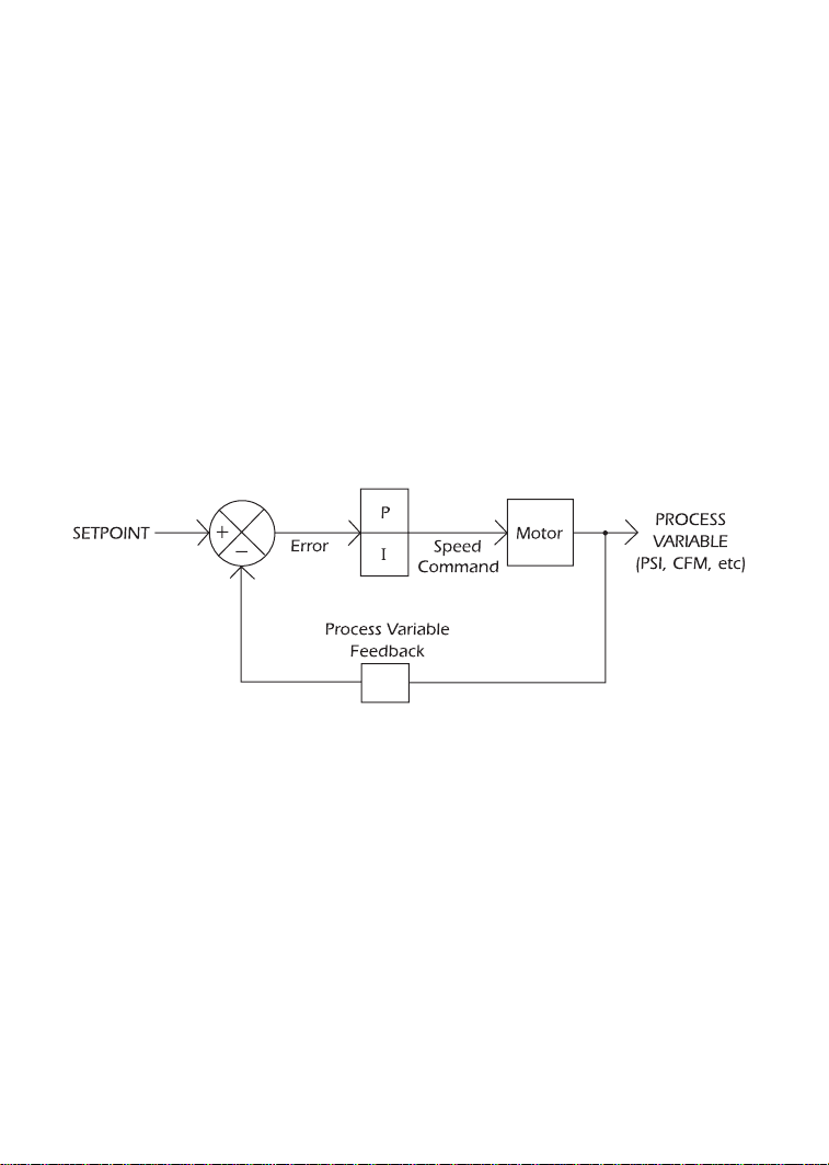
51
APPENDIX B – PI SETPOINT CONTROL OPTION
The following describes the PI Setpoint Control software option for the SpinMaster™ Plus drive.
This software option has additional parameters compared to the standard SpinMaster™ Plus
drive. Also, some of the parameters found in the standard drive have changed in the PI
version.
PI Setpoint Control allows the SpinMaster™ Plus drive to maintain a process setpoint, such as
PSI or CFM, without using an external controller. When PI is activated the SpinMaster™ Plus will
operate in a closed-loop fashion., automatically adjusting the motor speed to maintain the
process setpoint.
PI setpoint control requires feedback from the process in order to compare the actual process
value to the setpoint The difference between this value and the setpoint is called the error. The
SpinMaster™ Plus drive will increase or decrease the motor speed in an attempt to minimize
the error. By constantly adjusting the motor speed, the PI control will drive the process toward
the setpoint. Refer to the PI block diagram below:
B.1 DIRECT ACTING vs. REVERSE ACTING SYSTEMS
The PI function must be set to match the type of system that it will control. A direct (or normal)
acting system requires an increase in motor speed if the process variable decreases. A reverse
acting system requires a decrease in motor speed if the process variable decreases. Parameter
61 - PI MODE must be programmed to the setting that matches the system (normal or reverse
acting) and also the type of feedback signal that is used (0-10 VDC or 4-20 mA).
B.2 FEEDBACK DEVICES
A transducer or transmitter is required to monitor the process variable and provide feedback
to the PI unit in order to compare the process value with the desired setpoint. A transducer
outputs a signal corresponding to a fixed range of the process variable. A transmitter provides
offset and gain adjustment to allow the output signal to be adjusted to correspond to different
Page 56
ranges of the process variable. Typical output signals for transducers and transmitters are 0-10
VDC or 4-20 mA.
NOTE: if a 4-20 mA signal is used for feedback, and the signal is lost, the drive will display
“FL” to indicate the lost signal. The signal is considered lost if it drops below 2 mA.
B.3 SETPOINT REFERENCES
The following references can be used to adjust the process setpoint:
1. Keypad (L and M buttons)
2. 0-10 VDC signal (from speed pot or other source)
3. 4-20 mA signal
4. Preset Setpoints (using Preset Speeds #4 and #5)
NOTE: The setpoint reference and the PI feedback cannot be the same signal. If the drive is
mistakenly programmed so that the setpoint reference is the same as the feedback reference,
the setpoint reference will default to the L and M buttons.
B.4 ADDITIONS TO THE STANDARD PARAMETER MENU
NO. PARAMETER NAME RANGE OF ADJUSTMENT
FACTORY
DEFAULT
06 TB-14 OUTPUT MIN ALARM (11), MAX ALARM (12), NONE (01)
MIN/MAX ALARM (13),
13 TB-15- OUTPUT INV MIN ALARM (14), INV MAX ALARM (15) NONE (01)
INV MIN/MAX ALARM (16)
10 TB-13A FUNCTION KEYPAD SETPOINT (12) NONE (01)
11 TB-13B FUNCTION KEYPAD SETPOINT (09) NONE (01)
12 TB-13C FUNCTION KEYPAD SETPOINT (10) NONE (01)
45 SPD AT MIN SIGNAL MINIMUM FREQ - 999.0 Hz 0.0 Hz
46 SPD AT MAX SIGNAL MINIMUM FREQ - 999.0 Hz 60.0 Hz
61 PI MODE OFF (01), NORMAL 4-20 mA (02), OFF (01)
NORMAL 0-10 VDC (03),
REVERSE 4-20 mA (04),
REVERSE 0-10 VDC (05)
62 MIN FEEDBACK 0.0 - 999.0 0.0
63 MAX FEEDBACK 0.0 - 999.0 100.0
64 PROPORTIONAL GAIN 0.0 - 99.9 % 5.0 %
65 INTEGRAL GAIN 0.0 - 99.9 SEC 0.0 SEC
66 PI ACCEL/DECEL 0.0 - 999.0 SEC 20.0 SEC
67 MIN ALARM 0.0 - 999.0 0.0
68 MAX ALARM 0.0 - 999.0 0.0
69 0-10 VDC FEEDBACK (VIEW - ONLY) (N/A)
52
Page 57
B.4 ADDITIONS TO THE STANDARD PARAMETER MENU (cont)
NO. PARAMETER NAME RANGE OF ADJUSTMENT
FACTORY
DEFAULT
70 4-20 mA FEEDBACK (VIEW - ONLY) (N/A)
71 ACTUAL FEEDBACK (VIEW - ONLY) (N/A)
74 ANALOG INPUT FILTER 1-1000 2
75 SLEEP THRESHOLD 0.0 - 360 Hz 0.0. Hz
76 SLEEP DELAY 0.0 - 300 SEC 30.0 SEC
77 SLEEP BANDWIDTH MIN FEEDBACK - MAX FEEDBACK 0.0
B.5 DESCRIPTION OF PI PARAMETERS
P10 TB-13A FUNCTION SELECT
12 KEYPAD SETPOINT: This option has been added so that the L and M buttons on the
front of the drive can be used as the PI setpoint reference source. Closing TB-13A to
TB-2 will enable the PI mode and the L and M buttons can be used to select the
desired process setpoint.
P11 TB-13B FUNCTION SELECT
09 KEYPAD SETPOINT: This option has been added so that the L and M buttons on the
front of the drive can be used as the PI setpoint reference source. Closing TB-13A to
TB-2 will enable the PI mode and the L and M buttons can be used to select the
desired process setpoint.
P12 TB-13C FUNCTION SELECT
10 KEYPAD SETPOINT: This option has been added so that the L and M buttons on the
front of the drive can be used as the PI setpoint reference source. Closing TB-13A to
TB-2 will enable the PI mode and the L and M buttons can be used to select the
desired process setpoint.
P61 PI MODE
This parameter must be set to match the type of system and the type of feedback signal used.
A direct acting system is one that requires the motor speed to increase as the feedback signal
decreases, while a reverse acting system r equires the motor speed to decrease as the feedback
signal decreases.
01 DISABLED Disables the PI function to allow standard drive operation.
02 NORMAL 4-20 mA Enables the PI function for a direct acting system with a 4-20
mA feedback signal.
53
Page 58

P61 PI MODE (cont)
03 NORMAL 0-10 VDC Enables the PI function for a direct acting system with a 0-10
VDC feedback signal.
04 REVERSE 4-20 mA Enables the PI function for a reverse acting system with a 4-20
mA feedback signal.
05 REVERSE 0-10 VDC Enables the PI function for a reverse acting system with a 0-10
VDC feedback signal.
When PI is disabled, the drive will operate in an OPEN LOOP mode, responding directly to a
speed reference source selected using STANDARD SPEED SOURCE (Parameter 05) or terminals
TB-13A, 13B, and/or 13C).
P62 MIN FEEDBACK
This parameter should be set to the value of the process variable that corresponds to the
minimum transducer feedback signal (0 VDC or 4 mA). See the example below:
P63 MAX FEEDBACK
This parameter should be set to the value of the process variable that corresponds to the
maximum transducer feedback signal (10 VDC or 20 mA). See the example below:
Example: A 0-100 psi transducer outputs 4 mA at 0 psi and 20 mA at 100 psi. Set MIN
FEEDBACK to 0, and set MAX FEEDBACK to 100. The setpoint will then be adjustable between
0 and 100.
NOTE: If a reverse acting feedback device is being used, MIN FEEDBACK should be set to the
maximum process variable value, and MAX FEEDBACK should be set to the minimum process
variable value.
P64 PROPORTIONAL GAIN
The Proportional Gain setting repr esents the speed command output (in % of maximum speed)
that results from each 1% of error.
P65 INTEGRAL GAIN
The Integral Gain setting represents the ramp rate of the speed command output (in % of
maximum speed per second) that results from each 1% of error.
P66 PI ACCEL/DECEL
When the PI unit attempts to respond to a sudden step change in setpoint, the result can be
unstable operation. This parameter acts like a “filter’ and ramps the setpoint from the old value
54
Page 59

to the new value over a programmable period of time to smooth the PI unit’s response. If PI
ACCEL/DECEL is set to 0.0 seconds, it is effectively disabled.
P67 MIN ALARM
This parameter represents the process value that the feedback signal must fall below to
activate the MIN ALARM output (see Parameters 6 and 13).
P68 MAX ALARM
This parameter represents the process value that the feedback signal must exceed to activate
the MAX ALARM output (see Parameters 6 and 13).
NOTE: The MIN ALARM function can be used to start and stop the drive based on the level
of the PI feedback signal. This is done by wiring a 2-wire start/stop circuit through the drive’s
open-collector output, and setting the open-collector output for MIN ALARM (see Parameters
6 and13). When the signal drops below the MIN ALARM setting, the open-collector output will
de-energize, which will stop the drive. When the signal is equal to or greater than the MIN
ALARM setting, the open-collector output will energize and start the drive.
P69 0-10 VDC FEEDBACK
This can be used to monitor the PI feedback when using a 0-10 VDC feedback signal. The
displayed value will be scaled according to the MIN and MAX FEEDBACK parameters (62 and 63).
P70 4-20 mA FEEDBACK
This can be used to monitor the PI feedback when using a 4-20 mA feedback signal. The
displayed value will be scaled according to the MIN and MAX FEEDBACK parameters (62 and 63).
P71 ACTUAL FREQUENCY
This can be used to monitor the actual output frequency of the drive when operating in PI
mode, as the normal display is scaled to PI units according to the MIN and MAX FEEDBACK
parameters.
P74 ANALOG INPUT FILTER
This adjusts the filter on the analog input terminals (TB-5 and TB-25) to reduce the effect of any
electrical noise that may be present on the analog input signals. This filter works both in PI
mode and standard speed control mode. It should be set to the lowest value that yields
acceptable performance, as setting it too high may cause the drive to react too slowly to
signal changes. The range of adjustment is 1 to 1000, which actually corresponds to 0.01 to
10.0 seconds.
55
Page 60

P75 SLEEP THRESHOLD
The PI option has a Sleep Mode function that allows the drive to cease operation when system
demand falls below a preset level. This is to prevent the motor from operating at low speeds
for long periods of time.
When the commanded speed falls below the SLEEP THRESHOLD setting for the defined SLEEP
DELAY time (see P76 below), the drive will “go to sleep” and the motor will stop. The drive will
remain “sleeping” until it is commanded to operate at a speed that is 2 Hz above the SLEEP
THRESHOLD, at which point it will “wake up” and ramp the motor up to the commanded
speed.
NOTE 1: While the drive is in Sleep Mode, the display will read “SLP”.
NOTE 2: If the drive’s commanded speed goes below the SLEEP THRESHOLD, the SLEEP
DELAY timer will start to count down. If the commanded speed equals or exceeds the SLEEP
THRESHOLD before the SLEEP DELAY times out, the SLEEP DELAY timer will reset.
NOTE 3: If the drive is in a Stop state, and the commanded speed is below the SLEEP
THRESHOLD, the drive will immediately go to sleep upon a Start command, bypassing the
SLEEP DELAY.
P76 SLEEP DELAY
This sets the amount of time the drive must operate below the SLEEP THRESHOLD (see P75
above) before the drive “goes to sleep” and brings the motor to zero speed.
Example: SLEEP THRESHOLD is set to 15 Hz and SLEEP DELAY is set to 60 seconds. If the
drive operates below 15 Hz for 60 seconds, the drive will go to sleep and the motor will stop.
The drive will display “SLP”, and the drive will remain sleeping until the drive is commanded to
a speed equal to or greater than 17 Hz. At this point, the drive will wake up and ramp the
motor up to the commanded speed. This example assumes that SLEEP BANDWIDTH (P77) is
set to 0.
P77 SLEEP BANDWIDTH
This allows the PI feedback signal to determine when the drive should “wake up” when
operating in Sleep Mode. In process systems that utilize Integral Gain (see P65), the drive may
cycle in and out of Sleep Mode more often than desired, due to the Integral function of the
PI algorithm.
When SLEEP BANDWIDTH is used, the feedback signal must change by the programmed
amount before the drive will wake up.
56
Page 61

Example: In a normal-acting system, the PI setpoint is 50 PSI, SLEEP THRESHOLD is set to 20
Hz, and SLEEP BANDWIDTH is set to 5 PSI. The drive will enter Sleep Mode when the commanded speed drops below 20 Hz for the time defined in SLEEP DELAY. The drive will wake
up when the feedback signal drops below 45 PSI (50 PSI setpoint minus 5 PSI bandwidth = 45
PSI), even is the commanded speed is still below 20 Hz.
B.6 DESCRIPTION OF OTHER PARAMETERS
In addition to the PI feature, two parameters have been added, and additional options have
been added to the open-collector status outputs:
P06/P13TB-14/TB-15 OUTPUT
Three more options have been added to the open-collector outputs:
11 MIN ALARM: Opens when the feedback signal falls below the MIN ALARM setting.
12 MAX ALARM: Opens when the feedback signal exceeds the MAX ALARM setting.
13 MIN/MAX ALARM: Opens when the feedback signal falls below the MIN ALARM setting
or exceeds the MAX ALARM setting.
14 INV MIN ALARM: Opens when the feedback signal exceeds the MIN ALARM setting.
15 INV MAX ALARM: Opens when the feedback signal falls below the MAX ALARM setting.
16 INV MIN/MAX ALARM: Opens when the feedback signal is within the range defined by
the MIN ALARM and MAX ALARM.
P45 SPEED AT MIN SIGNAL
This sets the speed at which the drive will run when it receives the minimum speed reference
signal (0 VDC or 4 mA). This is used in conjunction with SPEED AT MAX SIGNAL (Parameter 46)
to define the speed range of the drive when following an analog speed reference signal.
P46 SPEED AT MAX SIGNAL
This sets the speed at which the drive will run when it receives the maximum speed reference
signal (10 VDC or 20 mA). This is used in conjunction with SPEED AT MIN SIGNAL (Parameter
45) to define the speed range of the drive when following an analog speed reference signal.
NOTE: If SPEED AT MIN SIGNAL is set higher than the SPEED AT MAX SIGNAL, the drive
will react inversely to the speed reference signal. Therefore, as the speed reference signal
increases, the drive speed will decrease, and vice-versa.
57
Page 62
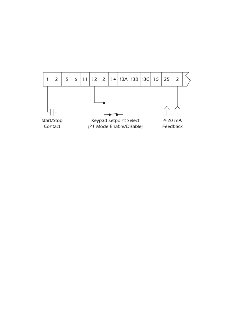
58
B.7 SpinMaster™ Plus PI CONTROL WIRING EXAMPLES
The following diagrams illustrate the most common PI control configurations. The wiring and
corresponding parameter settings are given. In these examples, TB-13A is use to select the
setpoint reference (TB-13B or TB-13C could also be used for this function). The examples show
a 2-wire start/stop circuit.
Example 1: Keypad Setpoint and 4-20 mA Feedback
• Set PI MODE (Parameter 61) to NORMAL 4-20 mA (02) or REVERSE 4-20 mA (04) depending
on the system. Refer to section B.1 to determine whether the system is normal or reverse
acting.
• Set TB-13A FUNCTION SELECT (Parameter 10) to KEYPAD SETPOINT (12).
• Close TB-13A to TB-2 to put the drive into PI mode. The L and M buttons can then be used
to adjust the PI setpoint.
• Open TB-13A to TB-2 to disable PI mode and control speed directly by the method selected
in STANDARD SPEED SOURCE (Parameter 05). For example, if Parameter 5 is set to 0-10
VDC, a speed pot could be used for manual speed control when the PI mode is disabled.
NOTE 1: When TB-13A is closed to TB-2, the drive’s display will flash “PIC” to indicate the drive
is in PI Control mode. When TB-13A is opened, the display will flash “SPd” to indicate the drive
is in Speed Control mode.
NOTE 2: The PI setpoint reference or manual speed control reference and the PI feedback
cannot be the same signal. If the drive is mistakenly programmed so that the reference signal
is the same as the feedback signal, the reference will default to the L and M buttons. For
example, if PI MODE (Parameter 61) is set to normal 0-10 VDC, the feedback signal must be
0-10 VDC, so a 0-10 VDC signal cannot be used as the PI setpoint reference or manual speed
control reference.
Page 63
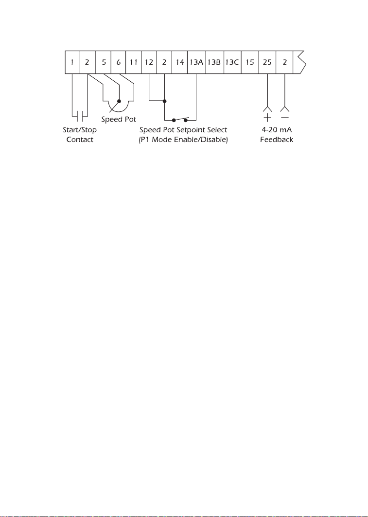
Example 2: Speed Pot Setpoint and 4-20 mA Feedback
• Set PI MODE (Parameter 61) to NORMAL 4-20 mA (02) or REVERSE 4-20 mA (04)
depending on the system. Refer to section B.1 to determine whether the system is normal
or reverse acting.
• Set TB-13A FUNCTION SELECT (Parameter 10) to 0-10 VDC (02).
• Close TB-13A to TB-2 to put the drive into PI mode. The Speed Pot can then be used to
adjust the PI setpoint.
• Open TB-13A to TB-2 to disable PI mode and control speed directly by the method selected
in STANDARD SPEED SOURCE (Parameter 05). For example, if Parameter 5 is set to 0-10
VDC, a speed pot could be used for manual speed control when the PI mode is disabled.
In this case, one speed pot would serve two purposes: adjusting the setpoint when PI mode
is enabled, and adjusting the motor speed directly when PI mode is disabled.
NOTE 1: When TB-13A is closed to TB-2, the drive’s display will flash “PIC” to indicate the drive
is in PI Control mode. When TB-13A is opened, the display will flash “SPd” to indicate the drive
is in Speed Control mode.
NOTE 2: The PI setpoint reference or manual speed control reference and the PI feedback
cannot be the same signal. If the drive is mistakenly programmed so that the reference signal
is the same as the feedback signal, the reference will default to the L and M buttons. For
example, if PI MODE (Parameter 61) is set to normal 0-10 VDC, the feedback signal must be
0-10 VDC, so a 0-10 VDC signal cannot be used as the PI setpoint reference or manual speed
control reference.
B.8 TUNING THE PI CONTROL
Once the PI control is configured properly, it needs to be turned in order to maintain the
process setpoint. First, set the Integral Gain (Parameter 65) to zero, and increase the
Proportional Gain (Parameter 64) until the system becomes unstable, then lower the gain until
the system stabilizes again. Set the Proportional Gain about 15% less than that value that
59
Page 64
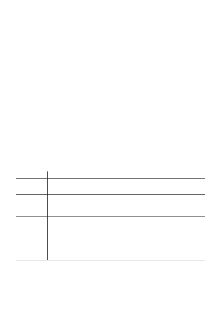
stabilizes the system. If only Proportional Gain is used, and the system is operating in a
steady-state condition (setpoint is fixed and process variable has settled to a fixed value), there
will always be a certain amount of error in the system. This is called the steady-state error.
Integral Gain (Parameter 65) is used to force the steady-state error to zero by increasing the
output speed command with respect to time. Over time, the error will be forced to zero
because the Integral term will continue to change the speed command, even after the
Proportional term reaches steady state and no longer affects the speed command. The Integral
Gain affects the rate of rise of the output speed command from the Integral term. Small
amounts of Integral Gain can cause large changes in PI performance, so care must be taken
when adjusting Integral Gain. Too much Integral Gain will result in overshoots, especially if
large step changes in error occur.
The other parameter setting that affects the response of the PI control is Parameter 66 - PI
ACCEL/DECEL. This sets the acceleration and deceleration rate of the setpoint reference into
the PI unit. When the setpoint changes, this function will “filter” the input to the PI unit by
ramping the setpoint reference from the previous value to the new value. This will help
prevent overshoots that can occur when the PI control attempts to respond to step changes
in setpoint, resulting in smoother operation. If PI ACCEL/DECEL is set to 0.0 seconds, it is
effectively disabled.
B.9 ADDITIONAL STATUS DISPLAYS
The PI option contains additional messages that may appear on the display:
60
PI OPTION DISPLAYS
DISPLAY DESCRIPTION
ACP AUTO CONTROL PAD: The L and M buttons are used to adjust the
setpoint in PI mode.
nCP MANUAL CONTROL PAD: The L and M buttons are used for manual
speed control when PI mode is enabled but the drive is operating in
open-loop mode.
FL FOLLOWER LOST: If a 4-20 mA signal is used as a speed reference, PI
setpoint reference, or PI feedback, and the signal drops below 2 mA, the
drive will trip and display “FL” to indicate that the signal is lost.
SLP SLEEP MODE: The drive .3 in sleep mode. The motor .3 at zero speed. The
drive will wake up when system demand requires a motor speed above
SLEEP THRESHOLD (P75).
Page 65

EC DECLARATION OF CONFORMITY
In accordance with EN45014:1998
Applied Council Directive(s): EMC Directive 89/336/EEC, as amended:
92/31/EEC and Low Voltage Directive 73/23/EEC, as amended: 93/68/EEC
We REGAL-BELOIT CORPORATION
200 State Street
Beloit, WI 53511-6254
U.S.A.
declare under our sole responsibility that the products to which this
Declaration relates, are in conformity with the relevant provisions of the following standards, provided that installations are carried out in accordance
with manufacturer’s instructions.
PRODUCTS RELATED TO DECLARATION
SpinMaster™ Plus AC Variable Frequency Motor Drives Models:
T310 T318 T329 T335 T341 T357 T363
T312 T324 T330 T336 T342 T358
T314 T325 T331 T337 T343 T359
T315 T326 T333 T338 T344 T360
T316 T327 T332 T339 T354 T361
T317 T328 T334 T340 T356 T362
NOTE: Model numbers may be followed by: “P” (PI setpoint), and/or “V” (high
frequency output)
RELEVANT EUROPEAN STANDARDS
EN 50081-2* Electromagnetic compatibility
– Generic emission standard – Part 2: Industrial environment
EN 50082-2* Electromagnetic compatibility
– Generic immunity standard – Part 2: Industrial environment
EN 50178:1998 Electronic equipment for use in power installations
* with suitable line filters that are properly installed.
YEAR OF CE Marking (Low Voltage Directive): 1999
Signature:
John Rydeski, Agency Project Engineer
Dated this 9th day of January 2002.
REGAL-BELOIT
Variable Speed AC Motors Drives
Page 66

A REGAL-BELOIT COMPANY
100 E. Randolph Street • P.O. Box 8003 • Wausau, WI 54402-8003
715-675-3311 • Fax:715-675-8030
www.marathonelectric.com
®
SB183 REV3 5494M/500/5-06/BAL/BH
 Loading...