

Page 1
CARNES COMPANY, 448 S.Main St., P.O.Box 930040, Verona, WI. 53593-0040 Phone:608/845-6411 Fax: 608/845-6470 [email protected] www.carnes.com
INSTALLATION, OPERATING AND MAINTENANCE INSTRUCTIONS
MODEL VGB A
SERIES BLOWER
CAUTION!
DO NOT INSTALL, USE OR OPERATE THIS EQUIPMENT UNTIL THIS MANUAL HAD BEEN READ AND UNDERSTOOD.
READ AND SAVE THESE SHEETS FOR FUTURE USE.
FORM 1501
RECEIVING INSPECTION:
Check for damage or missing parts immediately upon receipt. Ensure that wheel rotates freely.
REPORT ANY DAM-
AGE PROMPTLY TO CARRIER.
INSTALLATION:
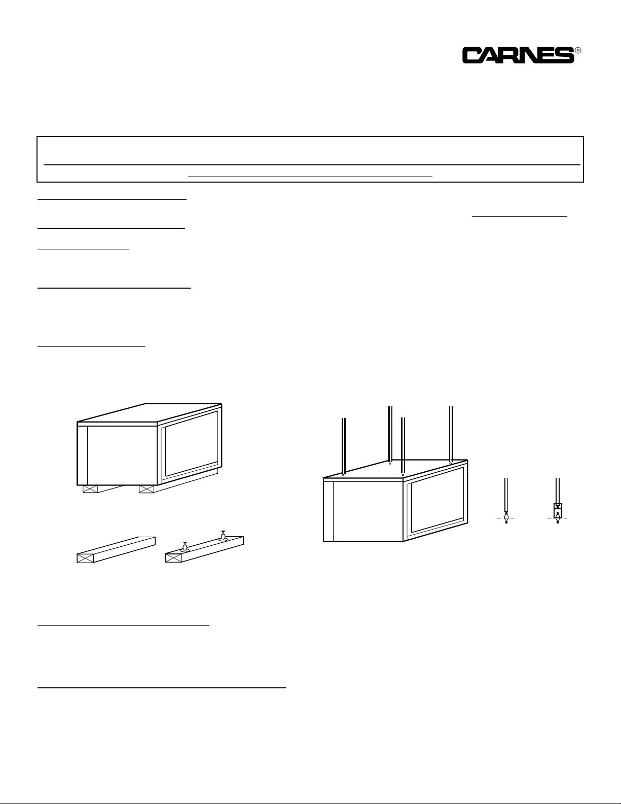
Model VDBA series blowers are suitable for both suspension or base mounting.
SUSPENSION MOUNTING:
Drill 4 — 7/8” diameter holes through the top using the inside top “hat section” channel as a guide. Extend 1/2” diameter
threaded mounting rod through the cabinet and the bottom channel and secure to both top and bottom. Ensure unit is
level.
BASE MOUNTING:
For base mounting, secure the unit through 4 — 7/8” holes located in the “hat section” channel in the bottom of the unit.
Ensure unit is level.
S
S
S
S
S
S
SUSPENDED MOUNT
OR
OR
RIGID
MOUNT
SPRING
ISOLATOR
VGBA
SERIES
BLOWER
VGBA
SERIES
BLOWER
BASE MOUNT
RIGID MOUNT
RUBBER ISOLATOR
Flexible inlet and outlet collars are recommended to minimize vibration transmission.
FORM 1501
MOTOR AND V-BELT DRIVES:
Mount motor with hardware provided and install pulleys and belt(s) with proper tension. Follow illustrated recommendations on belt installation on page 2.
BELT TENSION AND PULLEY ALIGNMENT:
1. Excessive belt tension is the number 1 cause of blower bearing failure.
2. Proper belt tension and pulley alignment are essential for trouble free operation.
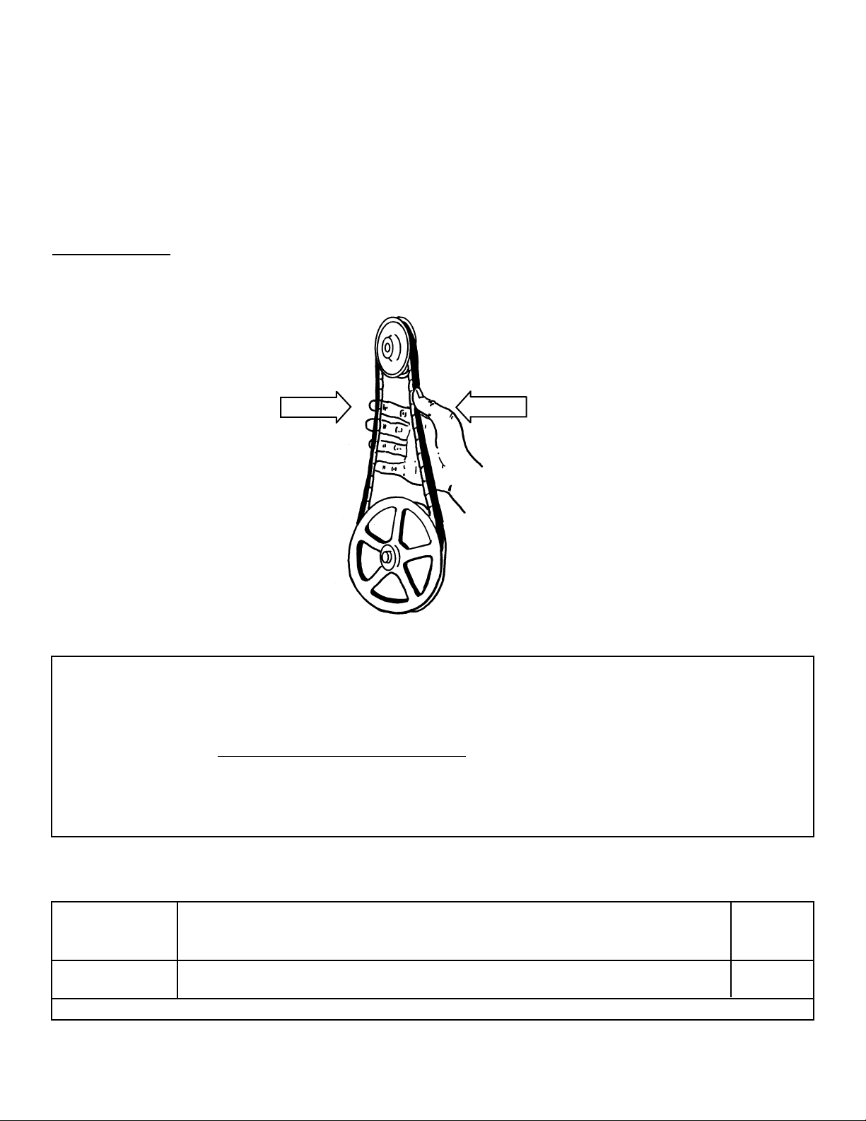
3. A simple “Rule of Thumb” for checking belt tension is illustrated on page 2.
(Continued on next page)
Page 2
2
4. When belt is grasped as shown on page 2, a total deflection of approximately 1” should be easily attained.
5. Insufficient deflection indicates that the belt is too tight, resulting in noise from excessive vibration, premature
bearing failure, and short belt life. Tight belts may overload a motor that would otherwise be adequate.
6. Excessive deflection is a indication that the belt is not tight enough. If not corrected, slippage could cause
loss of blower speed and belt failure through wear.
7. A belt should be just tight enough to avoid slippage.
8. Align pulleys with a straight edge to conserve belt life and eliminate unnecessary noise.
9. Check tension before start-up, after every pulley adjustment and regularly thereafter.
SET SCREWS:
Ensure all set screws on both pulleys and blower wheel are tight.
BELT SHOULD SQUEEZE
BY NO MORE THAN 1”
ELECTRICAL:
Connect motor in accordance with applicable codes. Provide properly sized motor overload protection to protect motor against electrical faults and system changes. Confirm proper motor rotation on star t-up.
MAINTENANCE:
Inspect periodically for mounting rigidity. Verify belt for wear and tension and adjust as required. Inspect wheel for any dust accumulation and clean as needed. Caution — Do not dislodge balancing clips. Check set screw for tightness.
LUBRICATION:
Insert bearings with sealed in lubricant are used on all 9200 ser ies models up to 15. No further lubrication is required. Models 18
and 20 use cast iron, pillow block, sealed type bearings. Re-lubrication is unnecessary under mot operating conditions. If lubrication
is required lubricant should be compatible to Esso Beacon #325.
3-1/4” Dia. Zinc Die Cast Blower Pulley — Dia. & RPM RangeBlade Length
Blower Model 5” 6” 7” 8” 9” 10” 12” Based On
824-1125 RPM 680-929 RPM 580-792 RPM 505-690 RPM 447-611 RPM 401-548 RPM 533-455 RPM Motor Frame
09 4L36 4L38 4L40* 4L42 4L44 4L45 - - -
10 4L38 4L40 4L41 4L43• 4L45 4L47 - - -
48 Frame
• Standard Drive with 3-1/4” x 1/2” v. s. Motor Pulley •• Standard Drive with 3-1/4” x 5.8” v. s. Motor Pulley
Model VGBA Series Blower Belt Length Selection Table
Page 3
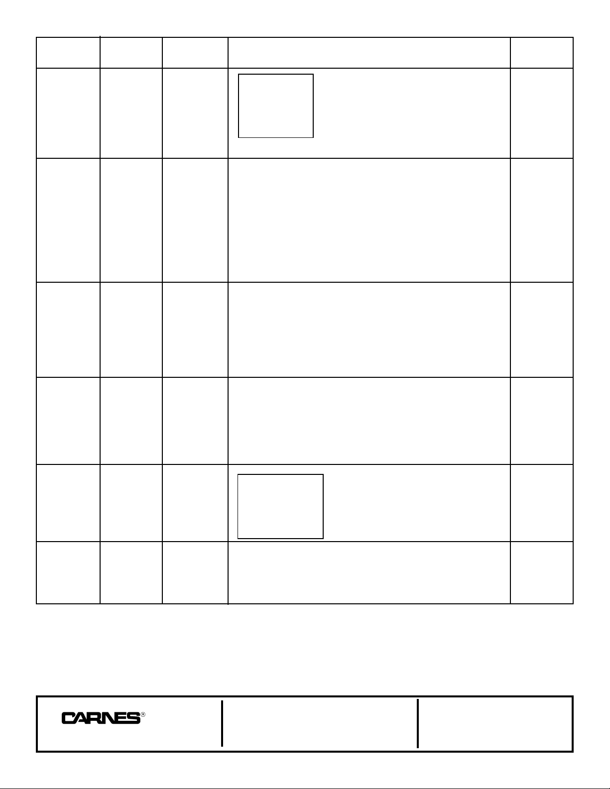
Motor Blower Blower Model Belt Length
Pulley Pulley Based On
Cast Iron Cast Iron RPM Range 09 10 12 15 18 20 Motor Frame
HB77T 756-568 B50 B55 B63 B68 Models
HB87T 677-500 Blower Pulley B52 B57 B65 B70 09 & 10
HB97T 596-447 Model Number B54 B59 B67 B72 48 Frame
#8325 HB107T 538-404 Specifies O.D. B55 B51 B68 B74 (Add 1” For
HB117T 491-368 B57 B62 B70 B75 56 Frame)
O.D. 3.25” HB127T 452-339 Eg. B59 B64 B72 B77
HB137T 418-314 HB47T = 4.7” O.D. B51 B55 B74 B79 Balance
HB157T 364-273 - - - B70 B77 B62 143, 145T
HB187T 304-228 - - - - - - B83 B88
HB47T 1630-1232 B36 B38 - - - - - - - - - - - HB57T 1329-1005 B38 B40 - - - - - - - - - - - HB67T 1121-848 B39 B41 - - - - - - - - - - - - 143
#IVL44 HB77T 969-733 B41 B43 B50 B53 B65 - - -
HB87T 854-645 B43 B45 B51 B55 B67 B72 &
HB97T 763-577 B45 B47 B53 B56 B68 B74
O.D. 4.15” HB107T 629-476 B48 B50 B56 B60 B72 B77 145T
HB117T 578-437 B48 B50 B56 B60 B72 B77
HB127T 578-437 B50 B52 B58 B61 B73 B78 Frame
HB137T 535-404 B52 B54 B60 B63 B75 B80
HB157T 466-352 B56 B58 - - - B67 B79 B84
HB187T 390-295 B63 B64 - - - - - - - - - - - -
HB77T 1253-1017 - - - - - - B52 B56 B67 - - HB87T 1104-896 - - - - - - B53 B57 B69 B74 182 & 184T
HB97T 1005-815 - - - - - - B55 B58 B70 B76 Frame
#8400 HB107T 907-750
HB117T 828-686 - - - - - - B57 B60 B72 B77
HB127T 756-618 - - - - - - B58 B52 B75 B80 (Deduct 2”
O.D. 4.15” HB137T 697-575 - - - - - - B62 B63 B77 B82 For 56, 143
HB157T 616-509 - - - - - - - - - B69 B81 B86 * 145T)
HB187T 522-435 - - - - - - - - - - - - B86 B91
HB87T 1104-896 - - - - - - B65 B58 B71 - - HB97T 1005-815 - - - - - - B57 B60 B72 - - - 182 & 184T
#8550 HB107T 907-750 - - - - - - B58 B62 B74 B79 Frame
HB117T 828-685 - - - - - - B60 B63 B75 B80
HB127T 756-618 - - - - - - B62 B65 B77 B82 (Deduct 2”
O.D. 5.35” HB137T 697-575 - - - - - - B54 B67 B79 B84 For 56, 143
HB157T 616-509 - - - - - - - - - B70 B72 B87 & 145T)
HB187T 522-435 - - - - - - - - - - - - B88 B92
Double Groove
11.0x2B 939-780 Note: - - - - - - (2) B78 (2) B83 213, 215T
#D8600 12.4x2B 839-700 Double Groove - - - - - - (2) B80 (2) B85
13.6x2B 759-631 Pulley Model Number - - - - - - (2) B82 (2) B87
15.4x2B 682-574 For O.D. Dimension - - - - - - (2) B85 (2) B90
O.D. 6” 18.4x2B 569-486 Eg. - - - - - - (2) B91 (2) B95 Frame
20.0x2B 516-429 11.0x2B=11.35 O.D. - - - - - - - - - - - -
11.0x2B 924-764 - - - - - - - - - - - - - - - (2) BX85 254T
2LVP38B60A 12.4x2B 817-678 - - - - - - - - - - - - - - - - - - Frame
13.6x2B 745-618 - - - - - - - - - - - - - - - (2) BX90 BX Belts Are
15.4Xxb 657-545 - - - - - - - - - - - - - - - (2) BX93 Not Available
O.D. 6.5” 18.4x2B 551-456 - - - - - - - - - - - - - - - (2) BX97 From
20.0x2b 507-419 - - - - - - - - - - - - - - - (2) BX100 Carnes
FOR FRACTIONAL HP APPLICATIONS “4L”BELTS MAY BE SUBSTITUTED BY ADDING 2” TO THE SPECIFIED “B” BELT. EG. 850 BELT = 4L52.
3
COMPANY
448 South Main Street
P. O. Box 930040
Verona, WI
53593-0040
Phone: 608/845-6411
Fax: 608/845-6470
E Mail: [email protected]
www.carnes.com
Page 4

 Loading...