

Page 1
IN-LINE CABINET
VENTILATORS
READ AND SAVE THESE INSTRUCTIONS
MODELS • VCDD210I • VCDD330I
®
Page 1
WARNING
TO REDUCE THE RISK OF FIRE, ELECTRIC SHOCK, OR INJURY TO PERSONS, OBSERVE THE FOLLOWING:
1.Use this unit only in the manner intended by the manufacturer. If
you have questions, contact the manufacturer at the address or
telephone number listed in the warranty.
2.Before servicing or cleaning unit, switch power off at service panel
and lock the service disconnecting means to prevent power from
being switched on accidentally. When the service disconnecting
means cannot be locked, securely fasten a prominent warning
device, such as a tag, to the service panel.
3.Installation work and electrical wiring must be done by a qualified person(s) in accordance with all applicable codes and standards, including fire-rated construction codes and standards.
4.Sufficient air is needed for proper combustion and exhausting of
gases through the flue (chimney) of fuel burning equipment to
prevent backdrafting. Follow the heating equipment
manufacturer’s guideline and safety standards such as those
published by the National Fire Protection Association (NFPA),
and the American Society for Heating, Refrigeration and Air Conditioning Engineers (ASHRAE), and the local code authorities.
5.When cutting or drilling into wall or ceiling, do not damage electrical wiring and other hidden utilities.
6.Ducted fans must always be vented to the outdoors.
7. This unit must be grounded.
CAUTION
1.For general ventilating use only. Do not use to exhaust hazardous or explosive materials and vapors.
2.To avoid motor bearing damage and noisy and/or unbalanced
impellers, keep drywall spray, construction dust, etc. off power
unit.
3.Please read specification label on product for further information and requirements.
!
PLAN INSTALLATION
MOUNTING
3/8” MIN.
THREADED ROD
(By Others)
ACCESS
PANEL
DUCT
FLANGES
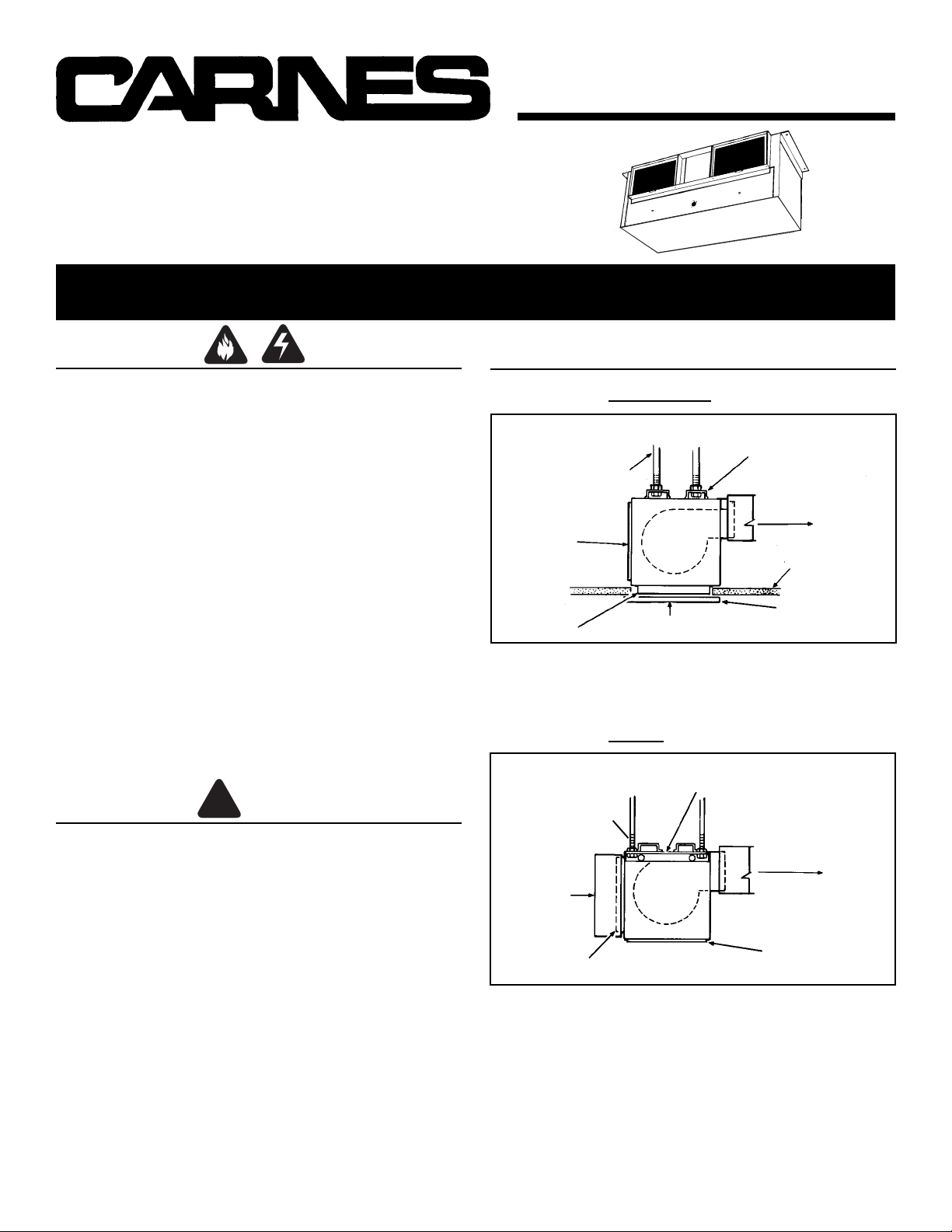
Factory shipped ready to be installed as a ceiling
MOUNTING
3/8” MIN.
THREADED ROD
(By Others)
INTAKE
DUCT
FLANGES
(Right-angle Discharge)
MOUNTING
CHANNELS
GRILLE KIT
INTAKE
ventilator with right-angle discharge.
(In-line Configuration)
ADJUSTABLE
BRACKET
INTAKE
ACCESS
PANEL
EXHAUST
CEILING
EXHAUST
Converted for in-line applications.
Page 2
MODELS • VCDD210I • VCDD330I
®
PLAN INSTALLATION (cont.) MOUNTING OPTIONS
CONVERTING FROM RIGHT-ANGLE T O IN-LINE
ACCESS
PANEL
EXHAUST
DUCT FLANGE
EXHAUST
DUCT FLANGE
INTAKE DUCT
FLANGES
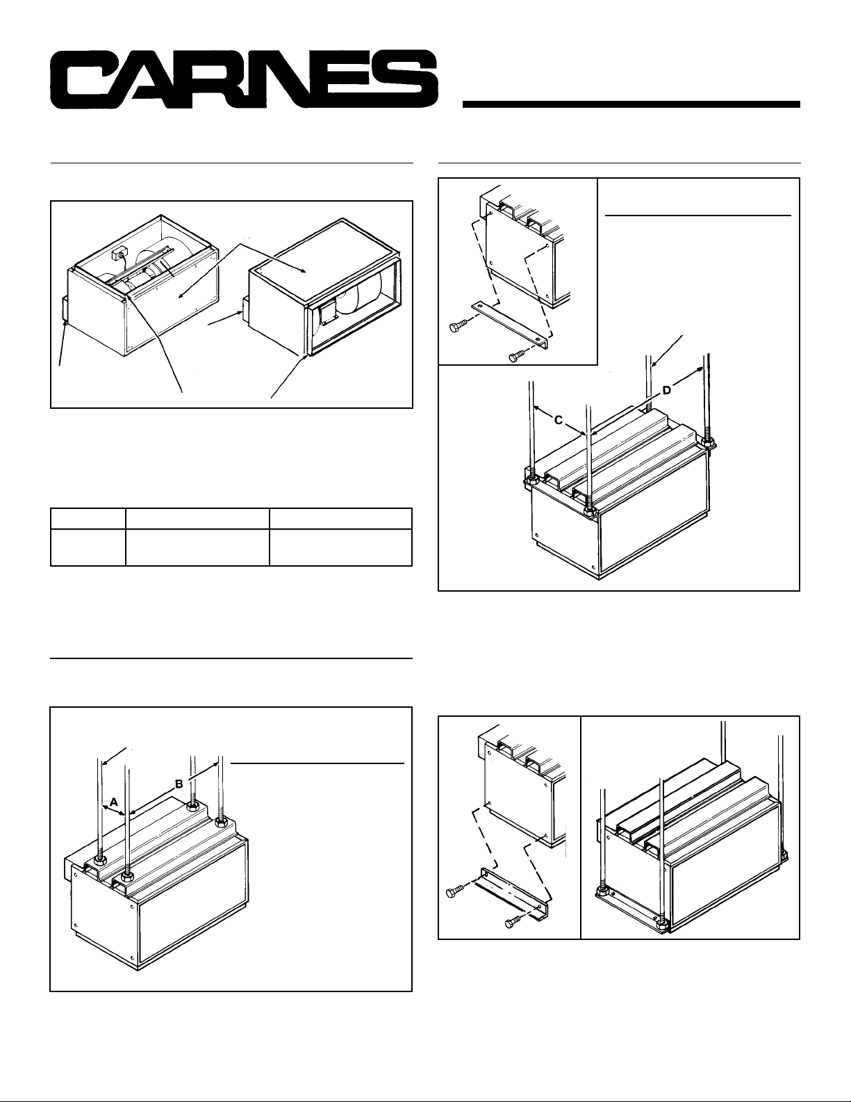
Remove and reverse duct flanges and access panel
positions on housing.
For correct intake and exhaust duct size, see Table 1.
DIM. VCDD210I VCDD330I
C 12-5/8” 12-5/8”
D 39-5/8” 47-3/8”
THREADED RODS
Page 2
3/8” MIN.
(By Others)
TABLE 1
MODEL INTAKE DUCT SIZE EXHAUST DUCT SIZE
VCDD210I 12-3/8” x 35-3/4” 7-3/4” x 33-3/4”
VCDD330I 14-1/2” x 43-1/2” 9-3/4” x 41-3/8”
MOUNTING OPTIONS
Provide solid support to minimize sound leves. There are two basic
mounting methods for these units.
3/8” MIN. THREADED RODS
(By Others)
DIM. VCDD210I VCDD330I
A 7-3/4” 10-1/4”
B 33-3/4” 41-3/4”
Mounting with threaded r od through adjustable
mounting brackets located at top of housing.
Mounting brackets can be bolted to housing ends in a variety of
configurations. Use screws and nuts provided in parts bag.
Typical mounting with threaded r od through
mounting channels on top of housing.
Mounting with threaded r ods through adjustable
mounting brackets located at bottom of housing.
If installing unit as a ceiling ventilator, make sure that either duct
flanges or housing will be flush with finished ceiling. Duct flanges
may be removed and discarded if the y interfere with a ceiling installation.
Page 3
®
MODELS • VCDD210I • VCDD330I
Page 3
MOUNTING OPTIONS
EXHAUST
SLEEPER
1-1/4”
INTAKE
ACCESS
PANEL
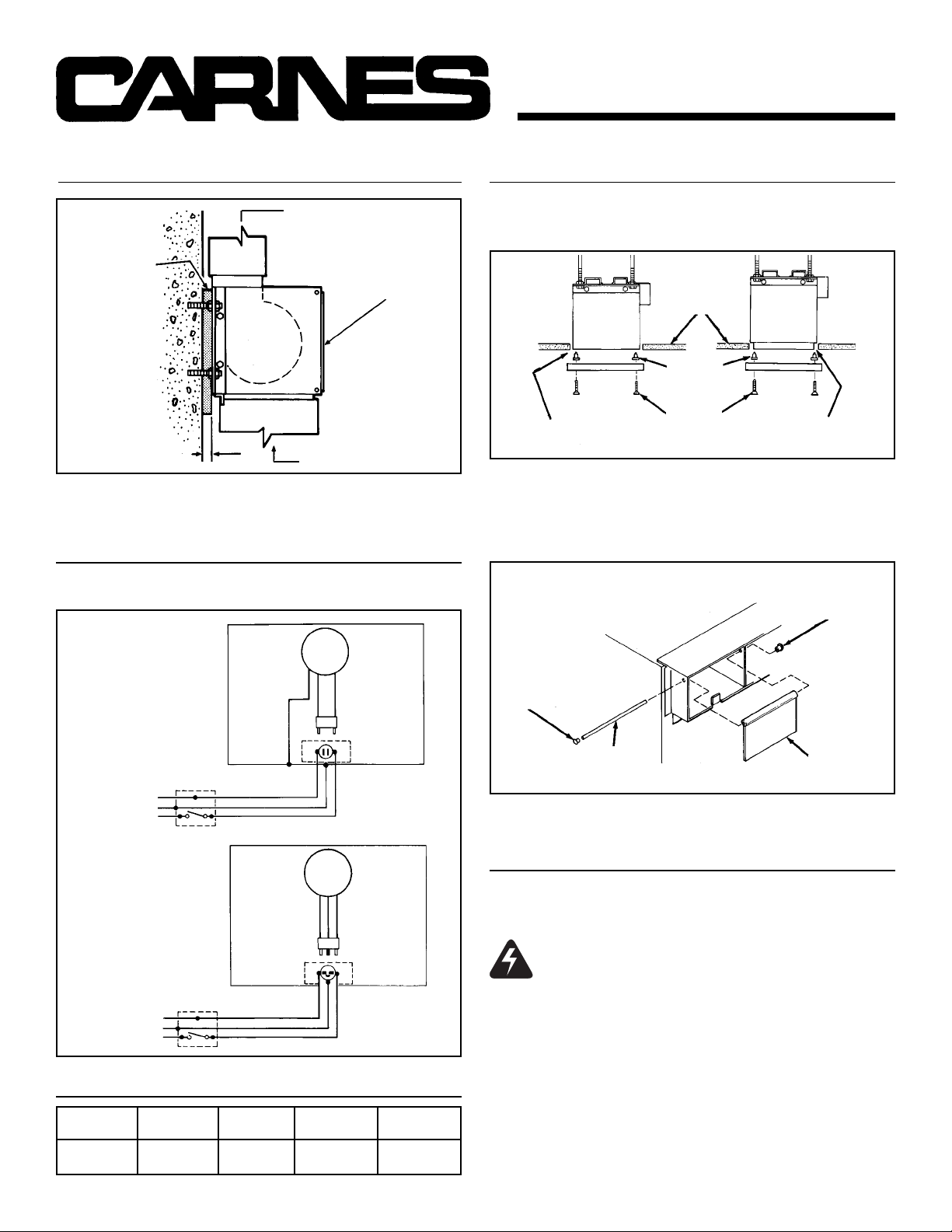
Typical wall mounting with 3/8” threaded fasteners
(by others) through mounting brackets.
ELECTRICAL CONNECTIONS
Connect electrical power cable to housing with proper connector
for type of cable used. Provide 6” leads inside wiring box.
A CCESSORY INSTALLATIONS
If ventilator will discharge directly outside, install adamper kit to
prevent backdrafts. A grille kit is available for applications where
ventilator is installed with direct or remote room air intake.
CEILING
GRILLE
SCREWS
CABINET FLUSH
GRILLE
NUTS
Snap screw bushings into square openings around intake
opening. Install grille with screws provided.
NOTE: If duct flanges around intak e opening interfere with installation, remove them. Make sure that housing is flush with finished
ceiling when ventilator is mounted.
DUCT FLANGES
INSIDE DAMPER
BUSHING
(Inside of frame)
WHITE
GND
BLK
RED
GND
BLK
MOTORMOTOR
MOTOR
MODEL
VCDD210I
LINE IN
120 VA C
60 HZ
MODEL
VCDD330I
LINE IN
240 VA C
60 HZ
1 PHASE
SPEED CONTROL
OR SWITCH
SPEED CONTROL
OR SWITCH
ACCESSORIES
MODEL KIT KIT CONTROL HANGER
VCDD210I D100 G102 72V / 72W V104
VCDD330I D101 G103 75V V104
DAMPER GRILLE SPEED VIBRATION
OUTSIDE
DAMPER BUSHING
(Snaps over rod)
(Inserts into inside bushing)
ROD
DAMPER FLAP
(Should open freely)
Install damper flap using rod pr ovided.
USE AND CARE
V entilator is designed for continuous operation. If desired, it ma y be
controlled using an on/off switch or a solid-state, variable speed
control. Follow wiring instructions packed with control, and adhere
to all local and state codes, and the National Electrical Code.
WARNING: To reduce the risk of electric shock,
disconnect from power supply before servicing.
To clean grille: Use appropriate vacuum attachment or remove
grille and clean with a soft cloth and mild soap or detergent. Dry
grille thoroughly before reinstalling.
To clean blower assembly: Remove either access panel or ceiling grille. Unplug blo wer assemb ly. Provide saf e support for b lo wer
assembly. Remove b lower mounting scre ws and lift b low er assembly out of housing. Gently vacuum housing and blower motor.
Vacuum or gently w ash bl ower wheels and housings. DO NOT ALLOW WATER TO ENTER MOTOR. Make sure blower assembly is
completely dry before reinstalling. Replace bl ower assembly in housing and plug assembly in. Replace grille and/or access panel.
Motor is permanently lubricated. Do not oil or disassemble motor.
Page 4
MODELS • VCDD210I • VCDD330I
®
SERVICE PARTS SERVICE PARTS
KEYMODEL VCDD210IMODEL VCDD330I
NO. PART NO. QTY. PART NO. QTY. DESCRIPTION
1 99420466 27 99420466 27 Insulation Clip
2 99170261 16 99170261 18 #5/16 - 18 x ½
Serrated Hex
Head Screw
3 98006462 2 98006462 2 Mounting Bracket
4 97008107 1 97008108 1 Cabinet Body
5 93260447 12 93260447 14 #5/16 - 18 Lock
Nut
6 99150471 2 ---- -- #10-32 x ½ Green
Ground Screw
7 99150490 42 99150490 44 #10B x 3/8
Serrated Pan
Head Screw
8 99270658 1 99270658 1 Outlet Box Cover
9 99160319 2 99160319 2 #6-32 x 3/8
Machine Screw
10 99270656 1 99270657 1 Receptacle
11 99270659 1 99270659 1 Outlet Box
12 98006364 2 98006376 2 Duct Inlet Flange -
short
13 98006363 2 98006375 2 Duct Inlet Flange -
long
14 99500335 2 99500339 2 Bottom Panel
Insulation
15 99500333 1 99500337 1 Back Panel
Insulation
16 99500334 2 99500338 2 End Panel
Insulation
17 98006699 1 98006700 1 Access Panel
18 99500336 1 99500340 1 Access Panel
Insulation
19 97007450 1 97007451 1 Blower Platform
20 98006475 4 98006476 4 Venturi Ring
21 97007453 1 97007455 1 Right Hand Scroll
22 99020172 1 99020174 1 Blower Wheel -
clockwise
23 99260477 10 99260477 12 ¼-20 Lock Nut
24 98006365 1 98006377 1 Blower Support
Channel
25 99080194 1 99080195 1 Motor
26 98006381 1 98006382 1 Motor Platform
27 99020173 1 99020175 1 Blower Wheel -
counter-clock-
wise
28 97007452 1 97007454 1 Left Hand Scroll
29 G-102 1 G-103 Grille Kit (contains
Key Nos. 30, 31
& 32)
30 99420470 8 99420470 8 Grille Nut
31 98006477 1 98006478 1 Grille
32 99150472 8 99150472 8 #8-18 x 1¼ Grille
Screw
33 D-100 1 D-101 1 Damper Kit
(contains Key
Nos. 34, 35, 36 &
37)
34 99100379 4 99100379 4 Damper Bushing
35 98006479 2 98006480 2 Damper Flap
36 98006481 2 98006472 2 Damper Rod
37 99760002 2 99760002 2 Damper Flap
Magnet
** 97007448 1 97007448 1 Parts Bag
(contains 4 ea. of
Key Nos. 2 & 5)
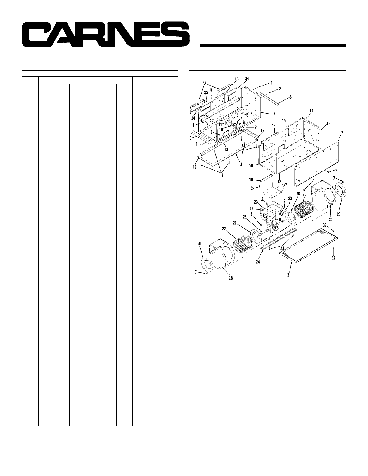
Order replacement parts by PART NO. - not by KEY NO.
** Not Shown
Page 4
11241
 Loading...