

Page 1
INSTALLATION, OPERATION & MAINTENANCE
ROOF AND WALL MOUNTED PROFILE FANS
DIRECT DRIVE
MODELS VULK & VELK
CARNES COMPANY, 448 S. Main St., P. O. Box 930040, Verona, WI 53593-0040 Phone: 608-845-6411 Fax: 608-845-6470 [email protected] www.carnes.com
INTRODUCTION
This manual is to be used as an aid in the proper installation, operation, and maintenance of the above Carnes fans.
This information is to be used as a general guide. Due to the variety and complexity of many installations it is the
responsibility of the purchaser to assure that qualified personnel handle these procedures.
RECEIVING, HANDLING, & STORAGE
1. Handle the fan with care. Avoid severe jarring or dropping of the unit.
2. Inspect the unit for damage upon delivery. If the unit has been damaged in transit it is the responsibility of the
recipient to file all freight claims.
3. Provide adequate, protected storage prior to installation.
FORM 1511, Page 1
MECHANICAL INSTALLATION CAUTIONS
1. Do not operate this fan in an environment where combustible or flammable materials, gasses, or fumes are
present unless it has been specifically designed and manufactured for use in that environment.
2. Turn the wheel by hand to check clearances. If necessary, adjust the wheel by moving the motor to center
the wheel over the inlet venturi and if necessary, raise or lower the wheel on the motor shaft.
3. Ensure that all fasteners and setscrews are tight.
ELECTRICAL INSTALLATION CAUTIONS
1. Be sure the supply voltage matches the motor nameplate voltage. On multiple voltage motors, check the
motor wiring to ensure that the motor has been wired for the correct voltage.
2. All fans must be grounded.
3. Keep all wiring clear of rotating components and moving parts such as gravity or motorized dampers.
4. Make sure power is locked OFF at the service entrance prior to wiring or otherwise approaching the fan.
5. A qualified electrician must do all electrical work in accordance with local and/or the National Electrical
Code (NEC).
FORM 1511
INSTALLATION OF ROOF TOP FANS
1. This fan is designed for exhaust applications only. Refer to the catalog V-104 for particular application details.
2. Any optional dampers should be mounted to allow free and unobstructed operation.
3. This fan requires a minimum of four (4) mounting fasteners, of the appropriate size and type in order to be
securely fastened to the roof curb. Be sure to use an approved sealant or gasket between the fan and curb to
prevent leaking and possible vibration.
INSTALLATION OF WALL MOUNTED FANS (VULK Only):
WALL OPENING PREPARATION
1. The wall opening must be sized according to the dimensions given in the Specification Sheet 11050 or on page 4 of
the Installation Instructions.
2. A mounting frame is supplied and must be attached to the wall on the side that the unit will be on.
3. Fasten the frame to the wall using a minimum size of 5/16” dia. thru-bolts, lag-bolts, expansion-bolts or other
appropriate heavy duty hardware for the type of wall construction at hand.
4. Push the supplied metal clips over the frame and line each of them up with one of the 4 unit mounting holes. Flat
side out.
WALL OPENING PREPARATION
1. Identify the Motor Compartment Vent Tube It is a short tube extending out of the motor compartment and passing
through the outer air shroud.
2. If a Damper is also being installed with this unit check its mounting position and wiring requirements (if motorized).
3. Apply a quality sealant around the frame in order to prevent water and air leaks between the wall and frame or
frame and unit.
4. Lift the unit into position on the wall with the Motor Compartment Vent Tube opening downward. This prevents
water from running into the motor compartment.
Page 2
5. Be sure the unit is in the final position and drive the four self-tapping screws through the pre-punched holes in
the Wall Mounting Cap and into the clips installed on the frame.
6. Route the motor supply power wires through the conduit opening next to the unit’s air intake.
7. If a wall grille is installed on the inside wall, the wall must be at least 6” thick.
2
MECHANICAL AND ELECTRICAL START-UP CAUTIONS:
1. Be sure the fans inlet, outlet, and the ductwork are open and free of loose objects.
2. Be sure all personnel are clear of fan rotating parts prior to start-up.
MAINTENANCE CAUTIONS:
Before performing any maintenance on the fan, be sure the power is locked OFF at the service entrance.
START-UP
1. Operate the fan under power briefly in order to check for proper rotation. Incorrect fan rotation will cause the
motor to over heat.
2. Check the operation of any dampers. Be sure they open and close fully.
MAINTENANCE
Fans should be carefully checked at least once a year. For critical or rugged applications, a routine check should be
done every 2 or 3 months.
1. A periodic check should consist of spinning the motor shaft with the power locked OFF to be sure the motor
turns freely, and the motor bearing run smoothly.
2. Check the wheel to motor shaft setscrew to ensure proper tightness.
3. Access to the motor compartment is obtained by removing the motor cover, which is held in place by (4) machine
screws.
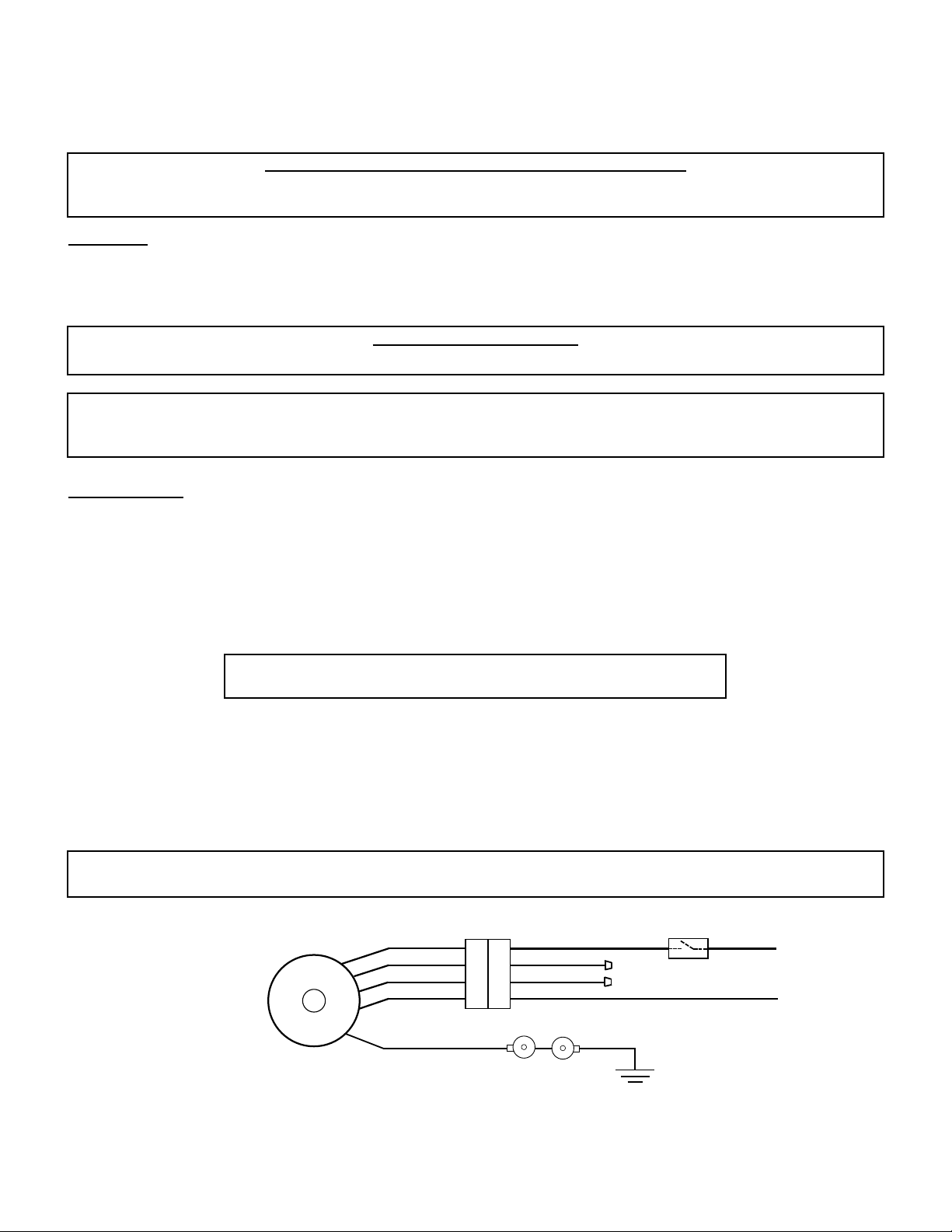
TYPICAL WIRING DIAGRAMS — (ALL MOTORS)
MOTOR
BLACK
BLUE
RED
WHITE
GREEN
HIGH
SPEED
SWITCH
L1
L2
THREE SPEED MOTOR DESCRIPTION
Carnes models VELK and VULK are equipped with three-speed ODP motors as standard. These motors each feature three very distinct speeds and horsepower’s, as shown in the performance charts on pages 3 and 5 of this
catalog. These motors can be wired direct or dedicated to a particular speed, for example, the motor can be “hard”
wired to high speed and the fan will always run on the high speed. These motors can also be wire to a three-speed
switch, allowing someone to “change” the speed via a switch between high-medium-low.
All motors supplied with Carnes fans carry a one-year warranty from the date of shipment. For repairs within the warranty period, the motor must be taken to the manufacturer’s authorized service dealer. Contact your Carnes
Representative for additional warranty details.
Page 3

3
MOTOR
BLACK
BLUE
RED
WHITE
GREEN
MED
MEDIUM
SWITCH
L1
L2
MOTOR
BLACK
BLUE
RED
WHITE
GREEN
LOW
SPEED
SWITCH
L1
L2
MOTOR
BLACK
BLUE
RED
WHITE
HI
MED
LOW OFF
GREEN
WITH
3-SPEED
SWITCH
3-SPEED
SWITCH
L1
L2
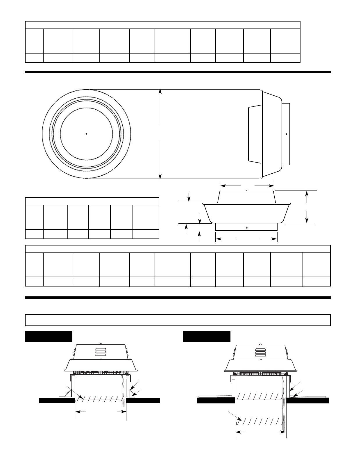
DIMENSIONS - VELK
Standard Material Thickness (Inches)
Curb Std. Fan Support
Unit Housing Cap Wheel Plate Brackets
Size (Alum.) (Alum.) Blades (Alum.) (Alum.)
06 .050 .050 Alum. .080 .125
E
D
B
C SQ.
A Dia.
[Dimensional Data Continued on Page 4]
Page 4
4
Standard Dimensions (Inches)
Unit Unit Inside Curb Curb Damper Max. Uni
Unit Diameter Length Curb Cap Cap Width O. D. Size Roof Weight
Size A B C E D SQ. SQ. Opening W/Motor
06 19-1/2 8 15-1/2 3/4 1-7/8 14 10 11 16
A
(Dia.)
Standard Material Thickness (Inches)
Curb Std. Fan Support
Unit Housing Cap Wheel Plate Brackets
Size (Alum.) (Alum.) Blades (Alum.) (Alum.)
06 .050 .050 Alum. .080 .125
F
D
B
C SQ.
E
Standard Dimensions (Inches)
Unit Unit Inside Motor Curb Curb Damper Roof/ Max. Uni Shroud
Unit Diameter Length Curb Cap Cover Cap Width O. D. Size Wall Weight Height
Size A B C E D SQ. SQ. Opening W/Motor F
06 22-1/4 8 15-1/2 13-1/2 1-7/8 14 10 11 16 5
DIMENSIONAL DATA - MODEL VULK
TYPICAL INSTALLATION DETAILS
FLASHING BY OTHERS
DAMPER
ROOF CURB
(INSULATED)
ROOF DECK
ROOF DECK
ROOF OPENING
Figure 1
VELK Low Profile Downblast Power Roof Ventilators and Model VULK Low Profile Upblast
ROOF DECK
ROOF DECK
SELF FLASHING
ROOF CURB
(INSULATED)
DAMPER
ROOF OPENING
FLASHING
BY OTHERS
Figure 2
Page 5
SELF FLASHING
ROOF CURB
(INSULATED)
DAMPER
FLASHING
BY OTHERS
ROOF DECK
ROOF DECK
FLASHING BY OTHERS
ROOF CURB
(INSULATED)
ROOF OPENING
Figure 3
Figure 4
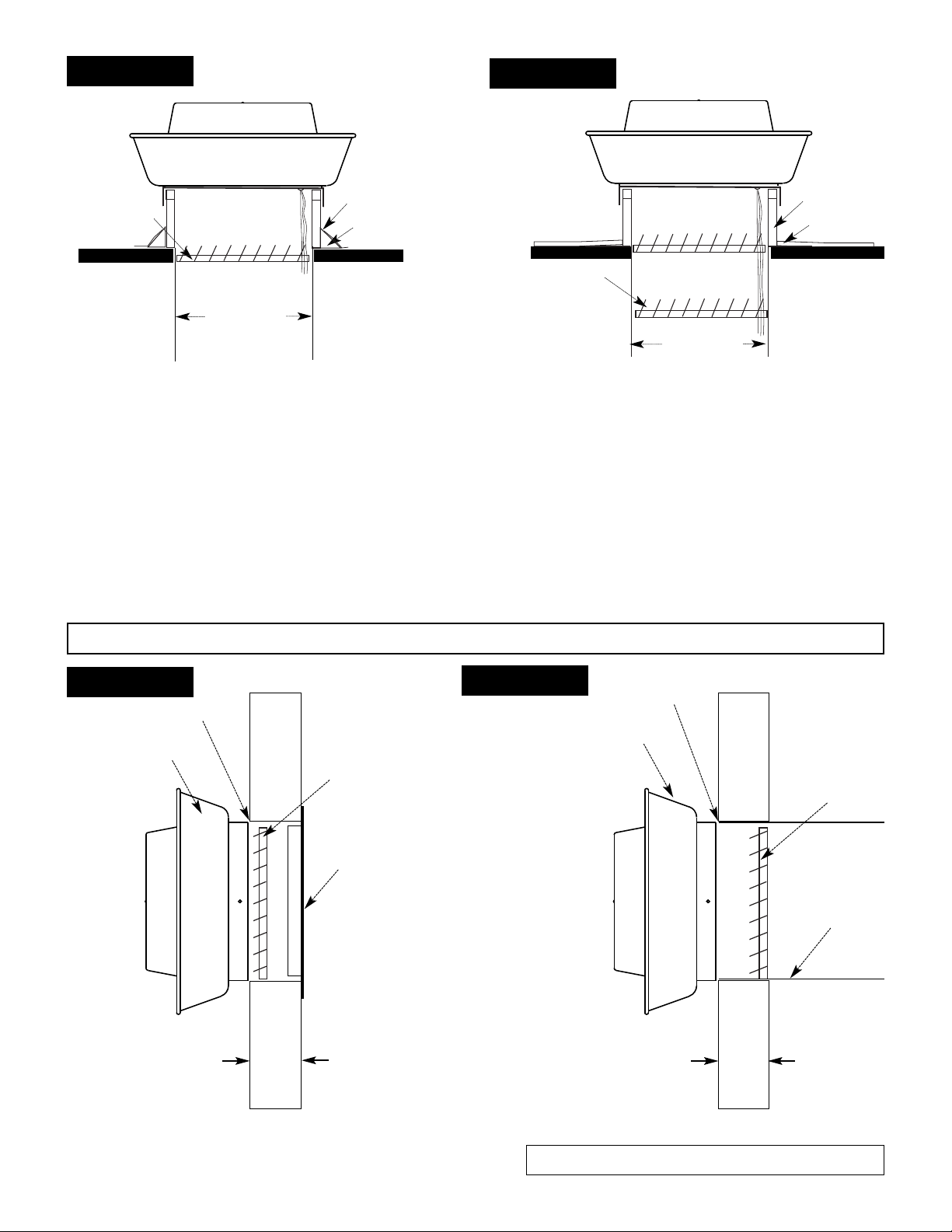
Figure 1 shows a typical Model VELK Low Profile
Downblast Power Roof Ventilator & Figure 3 shows a typical Model VULK Low Profile Upblast Power Roof
Ventilator installed without duct work. The roof flashing is
shown installed over a standard canted style roof curb. A
gravity operated backdraft damper is shown installed on
the damper shelf which is located at the base of the roof
curb. Power wiring is extended through the roof opening,
through the damper conduit knockout, into the fan wiring
chase and connecting to the factory wiring leads.
Figure 2 shows a typical Model VELK Low Profile
Downblast Power Roof Ventilator & Figure 4 shows a typical Model VULK Low Profile Upblast Power Roof
Ventilator installed with an exhaust duct. The duct is
shown extending through the roof opening and inside a
typical self flashing style roof curb. A gravity operated
backdraft damper is shown fastened to a 3/4” x 3/4” sheet
metal angle installed inside the exhaust duct. Power
wiring is extended through the roof opening, through the
damper conduit knockout, into the fan wiring chase and
connecting to the factory wiring leads.
ROOF DECK
ROOF DECK
DAMPER
ROOF OPENING
Figure 5: NON-DUCTED — Sidewall Installation Figure 6: DUCTED — Sidewall Installation
VULK
WALL FRAME
DAMPER
GRILLE
VULK
WALL FRAME
DAMPER
DUCT
6
Min.
6
Min.
Figure 5
Model VULK Sidewall Ventilator
5
Figure 6
[Installation Details Continued on Page 6]
Page 6
6
Figure 5 shows a typical Model VULK Sidewall ventilator
installed without duct work. The fan is mounted to the
wall by a factory provided wall mounting frame. A gravity operated backdraft damper is shown installed in the
wall, with a wall grille on the inside of the wall. Power
wiring is extended through the wall opening, through the
damper conduit knockout, into the fan wiring chase, and
connecting to the factory wiring leads.
Figure 6 shows a typical Model VULK Sidewall ventilator
installed with an exhaust duct. The duct is shown extending through the wall opening. The fan is mounted to the
wall by a factory provided wall mounting frame. A gravity backdraft damper is shown installed in the ductwork.
Power wiring is extended through the wall opening,
through the damper conduit knockout, into the fan wiring
chase, and connecting to the factory wiring leads.
Proper fan performance requires uniform and stable airflow at the fan inlet. Avoid transitions,
obstructions, elbows or other duct fittings near the fan inlet.
Typical roof curb height is 8” to 12” above the roof deck. Additional height reduces the likelihood
of snow or rain entering through the roof opening.
Installation and electrical work should be performed by qualified personnel and must be in accordance with all applicable code requirements.
For protection of personnel, inlet guards are recommended when the fan is within reach (or within 7 feet) of occupied areas or work areas.
448 S. Main St., P. O. Box 930040, Verona, WI 53593-0040
Phone: 608.845.6411 Fax: 608.845.6470
[email protected] www.carnes.com
 Loading...