

Page 1

FORM 1408-A
INSTALLATION, OPERATING AND MAINTENANCE INSTRUCTIONS
CENTRIFUGAL SPUN ALUMINUM UPBLAST FANS
MODEL VU - BELT and DIRECT DRIVE
CAUTION!
DO NOT INSTALL, USE OR OPERATE THIS EQUIPMENT UNTIL THIS
MANUAL HAS BEEN READ AND UNDERSTOOD. READ AND SAVE THESE INSTRUCTIONS FOR FUTURE USE.
RECEIVING, HANDLING AND STORAGE
1. Handle the fan with care. Avoid severe jarring or dropping of the unit.
2. Carefully inspect the unit for damage upon delivery. If the unit has been damaged in transit it is the responsibility
of the recipient to make all claims against the carrier.
3. Provide adequate, protected storage prior to installation.
INSTALLATION
1. Upon unpacking, inspect the unit for any damage that may have occurred in transit. Check also for loose or
missing parts.
2. CAUTION! This fan contains rotating parts and requires electrical service. Appropriate safety precautions
should be taken during installation, operation and maintenance.
3. WARNING! Do not install or operate this fan in environment or atmosphere where combustible or flammable
materials, gasses or fumes are present, unless it has been specifically designed and manufactured for use in that
environment. Explosion or Fire could result!
4. This ventilator requires a minimum of four (4) mounting fasteners, of the appropriate size and type in order to be
securely fastened to the roof curb. Be sure to use an approved sealant between the fan and curb to prevent
leaking.
5. A damper, if used, should be securely mounted within the ductwork in a manner which allows free and unobstructed operation. Fan wiring should not interfer with damper blades.
6. CAUTION! All electrical work must be done in accordance with local and/or national electrical code as
applicable. If you are unfamiliar with methods of installing electrical wiring, secure the services of a qualified
electrician.
7. WARNING! This product must be grounded.
8. DANGER! Make sure power is turned off and locked in the OFF position at the service entrance before
installing, wiring or servicing fan.
9. CAUTION! Before wiring the motor, check the supply voltage against the motor nameplate voltage. High
or low voltage can damage the motor and void the motor warranty.
10. Power should be routed through the conduit openings provided.
11. Access to the motor compartment is possible by either removing the motor cover or motor tube/motor cover
assembly.
12. WARNING! Be sure to keep all wiring clear of rotating or moving parts.
13. WARNING! Before starting the fan, turn the wheel to assure it rotates freely. If needed, adjust the wheel/
shaft/bearing/motor position as required to achieve necessary clearances.
14. CAUTION! On belt drive units assure belts are tensioned and aligned properly. (See Maintenance section.)
15. WARNING! Check all set screws and keys. Tighten as necessary prior to fan startup. Do not over torque
16. Remount motor cover/motor tube, do not over torque fasteners (30 in. - lb. maximum)
FORM 1408-A, Page 1
CARNES COMPANY, 448 S. Main St., P. O. Box 930040, Verona, WI. 53593-0040 Phone:608/845-6411 Fax: 608/845-6504 [email protected] www.carnes.com
Page 2
OPERATION
1. CAUTION! Check that the fan inlet/ductwork/exhaust openings are clean and free of obstructions. Poor inlet con-
ditions will result in seriously reduced fan performance.
2. WARNING! This fan contains rotating parts. Appropriate safety precautions should be taken during operation.
3. Operate under power and check for correct wheel rotation direction (clockwise when looking at top of the wheel).
4. CAUTION! Incorrect rotation can damage the fan motor and seriously impede fan operation.
MAINTENANCE
1. DANGER! Before performing and maintenance on the fan, be sure power is turned off and locked in the OFF
position at the service entrance before servicing the fan.
2. Ventilators should be carefully checked at least once a year. For critical or rugged applications, a routine check
every two or three months is suggested.
3. All motors supplied with CARNES ventilators carry a one year warranty from date of shipment. For repairs within
the warranty period, the motor must be taken to the motor manufacturer’s authorized service dealer. Contact your
CARNES representative for additional warranty details.
4. Access to the motor compartment is possible by removing the motor cover or motor cover/motor tube assembly.
5. A periodic motor check should consist of spinning the motor shaft with the power off to be sure the motor turns
freely and the bearings run smoothly. The belt on belt driven units should be removed from the motor sheave.
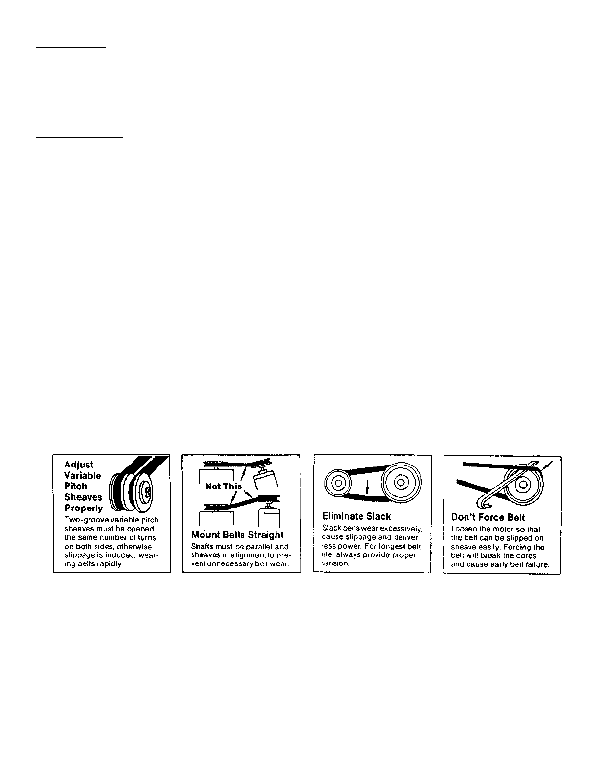
6. CAUTION! When removing or installing a belt, do not force the belt over the sheave. Loosen the motor mount so
that the belt can be easily slipped over the sheave.
7. The belt on belt driven units should be removed and carefully checked for radial cracks, ply separation or irregular
wear. A small irregularity in the contact surface of the belt will result in noisy operation. If any of these defects are
apparent, the belt should be replaced. Check the sheave also for chipping, dents or rough surfaces which could
damage the belt.
8. CAUTION! The correct belt tension is important. Too tight a belt will result in excess bearing pressure on the
motor bearings and shaft pillow blocks, and may also overload the motor. Too loose a belt will result in slippage
which will quickly “burn” out belts. A belt should feel “live” when thumped, approximately 1/4” belt deflection when
subjected to finger pressure (3 to 5 lbs.) at midpoint between sheaves.
9. CAUTION! The belt alignment should also be checked to be sure the belt is running perpendicular to the rotating
shafts. Motor and drive shafts must be parallel. Improper alignment will result in excessive belt wear.
10. CAUTION! Check sheave set screws to ensure tightness. Proper keys must be in keyways.
11. CAUTION! Do not readjust variable pitch sheave without checking motor amps. Do not readjust variable pitch
sheaves above the maximum catalog RPM for unit and motor. If fixed sheaves are replaced, use only sheaves of
identical size and type.
12. CAUTION! If adjustment of two groove variable pitch sheaves is required, each sheave must be opened or closed
the same number of turns. Improper adjustment can cause excessive belt wear and premature failure.
2
Page 3
3
13. If unit is to be left idle for an extended period (especially over summer months), it is recommended that belts be
removed and stored in a cool, dry place to avoid premature belt failure.
14. The standard pillow block bearings on CARNES belt driven ventilators are permanently lubicated and are supplied
with an oil base corrosion preventive compound. These should not require any service, except that during the first
few months of operation it is recommended the set screws holding the shaft be checked to be sure they are
tight. (Proper tightness will permanently defor Allen wrench).
15. The centrifugal wheel should not require maintenance except for removing foreign materials that may accumulate
on the blades. The balance weights should not be disturbed. If a wheel has to be removed from the shaft, do not
apply force that will damage the bearings or warp the wheel. Use a wheel puller.
16. Access for wheel alignment purposes can be obtained by removing the motor lid and/or motor tube. Lateral
adjustment is made with the motor mount. Vertical adjustment is made at the bears.
17. Should it be necessary to remove the wheel, access is through the fan plate. Do not remove the motor/motor
mount assembly. Carefully support the motor/motor mount assembly and remove all the fan plate fasteners.
Carefully remove the entire assembly from the unit base. To rebuild, assemble in reverse order.
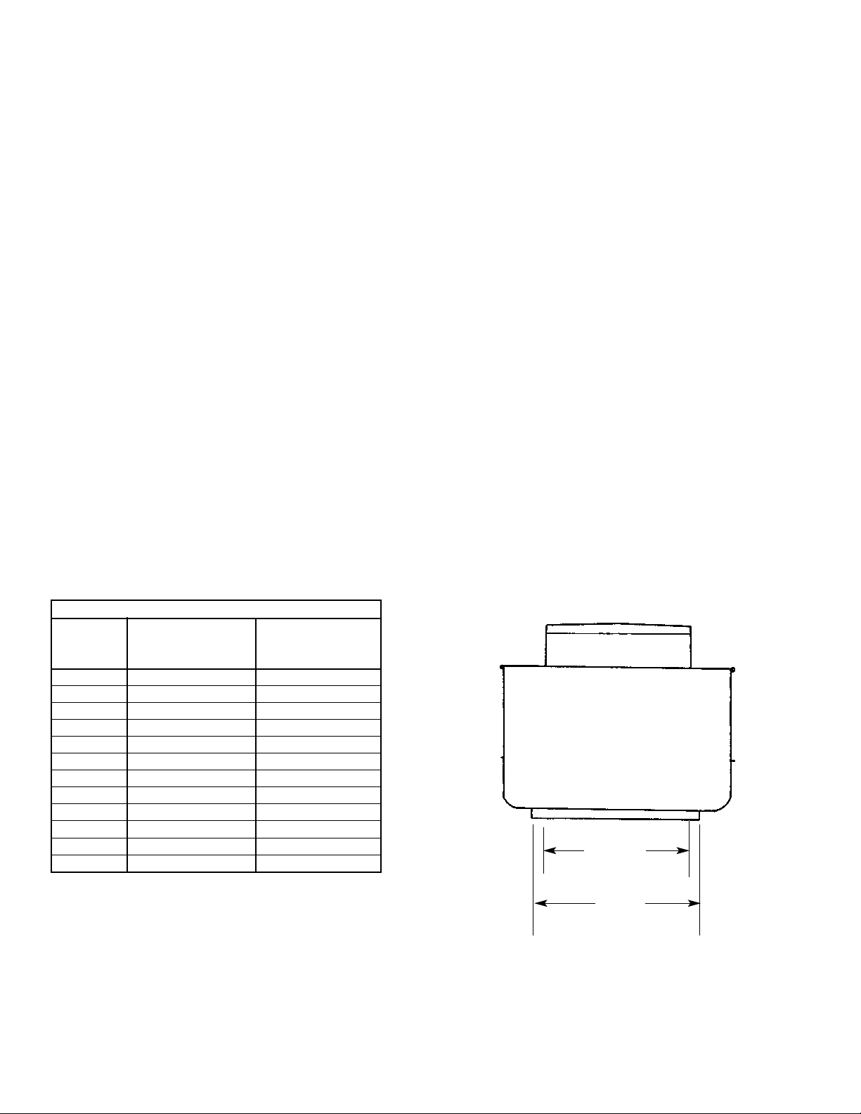
DIMENSIONS LISTED IN INCHES
INSIDE
UNIT CURB ROOF
SIZE CAP OPENING
06 15-1/2 11
08 15-1/2 11
10 17-5/8 13
12 17-5/8 13
15 20-1/2 16
18 25 20-1/2
21 28-1/8 23-1/2
24 31-1/8 26-1/2
30 40-1/8 35-1/2
36 46-1/8 41-1/2
42 54-1/8 49-1/2
48 58-1/8 53-1/2
INSIDE
CURB
CAP
ROOF
OPENING
Page 4
4
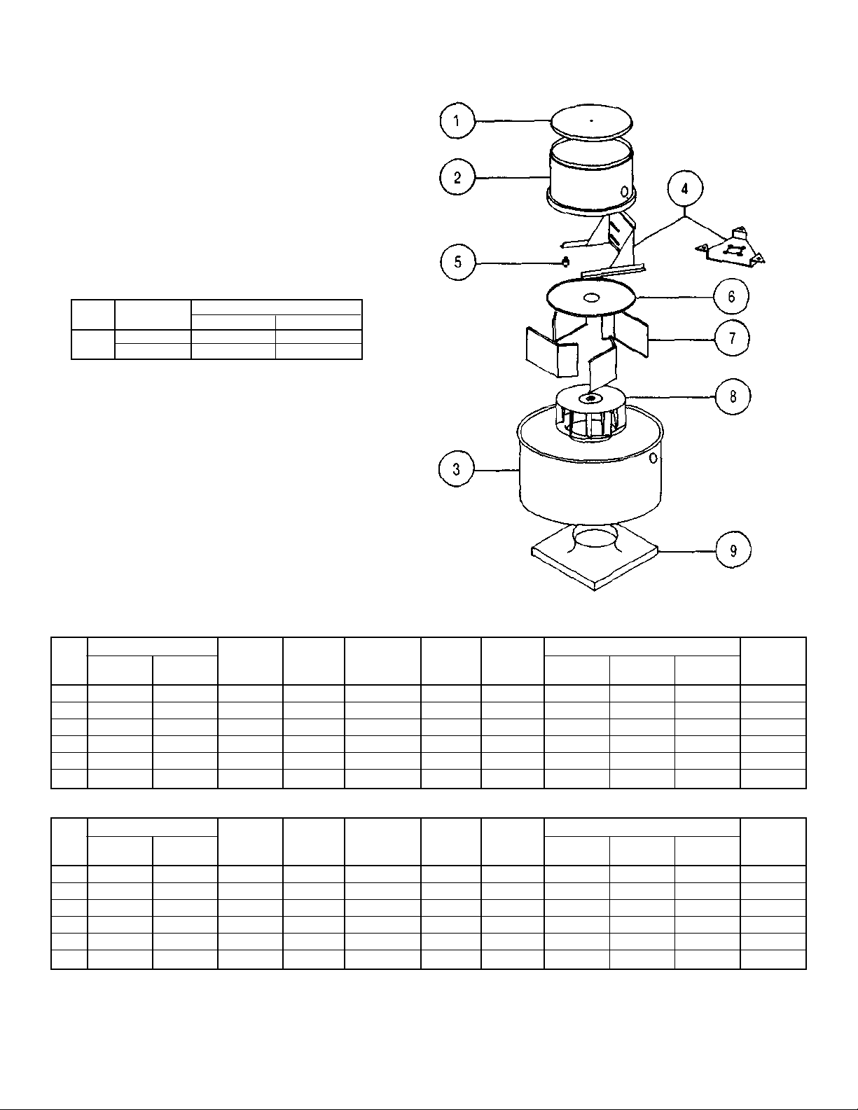
MODEL VUDK— DIRECT DRIVE - PARTS LIST
Unit Motor Unit Construction
Size Type Standard Extended
06 - 18 ODP, 1-Speed All —
Others — All
Other motor types include:
2-Speed
Totally Enclosed
Explosion Proof
STANDARD
Motor Cover Motor
4
Wheel (Bore Size)
8
Unit Outer
3
Mount Vibration
5
Fan6Diffusers
7
Curb
9
Size Lid
1
Tube
2
Shroud Assem’y Isolators Plate (Set of 4) 1/2” 5/8” 7/8” Cap
06 384-6521 384-6503 384-6441 632-0070 (3) 998-8126 384-2511 384-2461 384-0542 384-0543 — 384-2401
08 384-6521 384-6503 384-6442 632-0070 (3) 998-8126 384-2511 384-2462 384-0546 384-0547 — 384-2401
10 384-6521 384-6503 384-6443 632-0661 (3) 998-8126 384-2512 384-2481 384-0550 384-0551 — 384-2402
12 384-6521 384-6503 384-6444 632-0661 (4) 998-8126 384-2512 384-2482 384-0553 384-0554 384-0556 384-2402
15 384-6522 384-6506 384-6445 632-0663 (4) 998-8126 384-2513 384-2483 384-0557 384-0558 384-0560 384-2403
18 384-6523 384-6509 384-6446 632-0665 (4) 998-8126 384-2514 384-2484 384-0561 384-0562 384-0564 384-2404
EXTENDED
Motor Cover Motor
4
Vibration
5
Wheel (Bore Size)
8
Unit Outer
3
Mount Isolators Fan6Diffusers
7
Curb
9
Size Lid
1
Tube
2
Shroud Assem’y (4 Req.d) Plate (Set of 4) 1/2” 5/8” 7/8” Cap
06 384-6521 384-6504 384-6441 632-0661 998-6126 384-2511 384-2461 384-0542 384-0543 — 384-2401
08 384-6521 384-6504 384-6442 632-0661 998-6126 384-2511 384-2462 384-0546 384-0547 — 384-2401
10 384-6521 384-6504 384-6443 632-0661 998-6126 384-2512 384-2481 384-0550 384-0551 — 384-2402
12 384-6521 384-6504 384-6444 632-0661 998-6126 384-2512 384-2482 384-0553 384-0554 384-0556 384-2402
15 384-6522 384-6507 384-6445 632-0663 998-6126 384-2513 384-2483 384-0557 384-9558 384-0560 384-2403
18 384-6523 384-6510 384-6446 632-0665 998-6126 384-2514 384-2484 384-0561 384-0562 384-0564 384-2404
Page 5
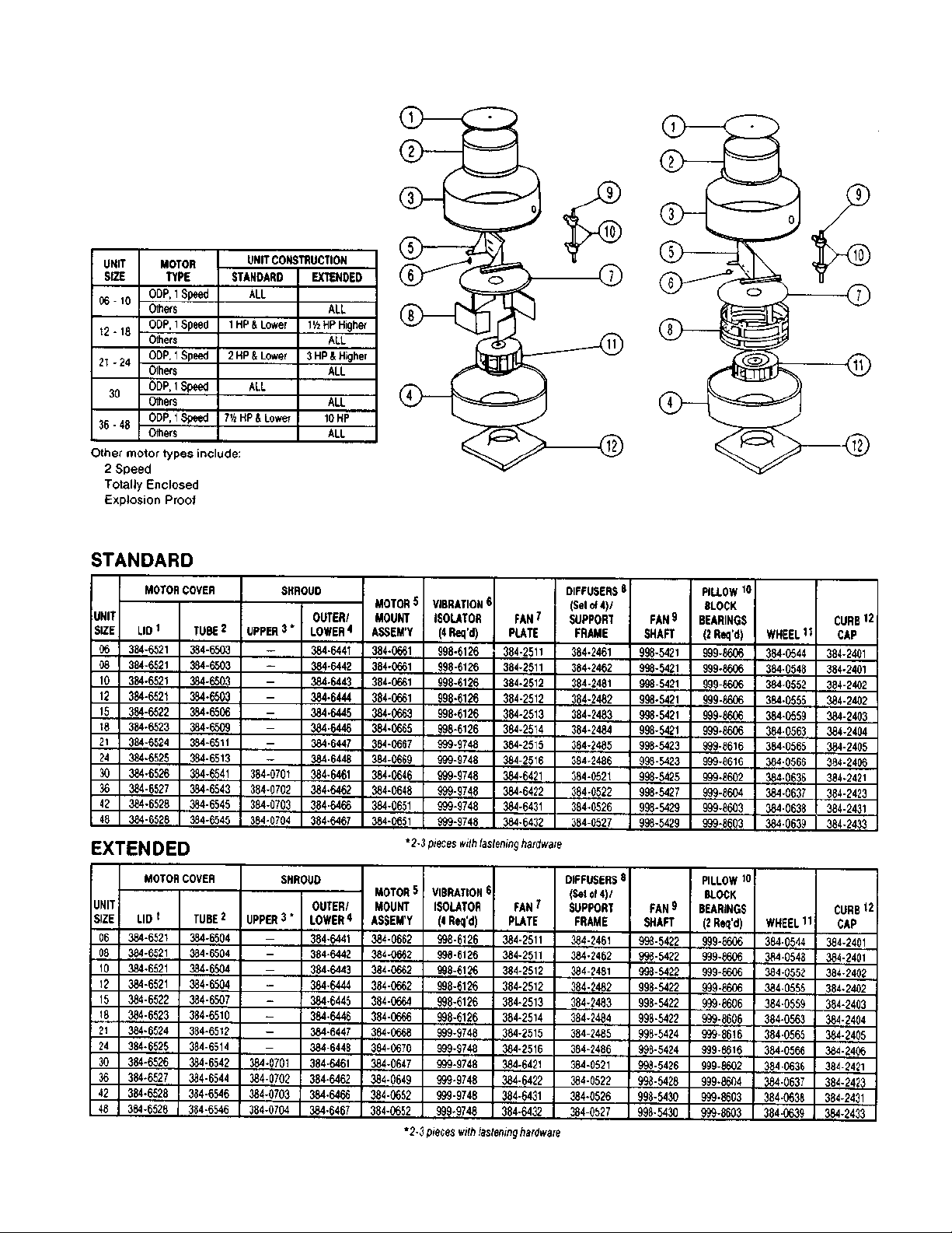
MODEL VUBK— BELT DRIVE - PARTS LIST
5
Page 6

COMPANY
448 South Main Street
P. O. Box 930040
Verona, WI
53593-0040
Phone: 608-845-6411
Fax: 608-845-6504
E Mail: [email protected]
www.carnes.com
6
 Loading...