

Page 1

PIXMA MP180 / MP460
SERVICE REFERENCE MANUAL
(Differences from the base models, PIXMA MP170 / MP450, only)
Part 1: MAINTENANCE
1. Maintenance
2. Error Display
3. Repair
Part 3: APPENDIX
2. Connector Location and Pin Layout
3. Specifications
Attachment 1: PARTS LIST (for Asia)
QY8-13AX-010
First Edition: June 16, 2006
Second Edition: June 23, 2006
Canon Inc.
(1/1)
Page 2
Part 1: MAINTENANCE
1. Maintenance
1-3. Product Life
(1) Machine
Same as the MP170 and MP450.
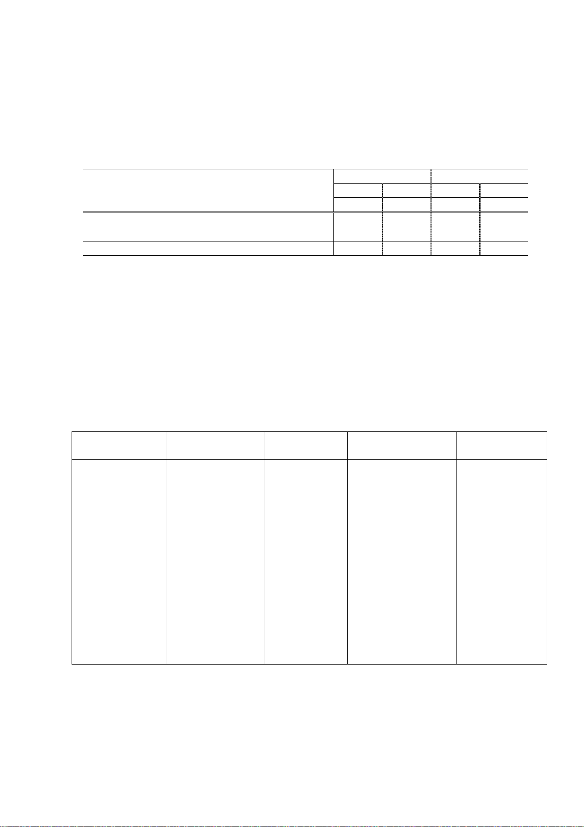
(2) Ink cartridge
Units: pages
Standard High capacity
BK CL BK CL
PG-40 CL-40 PG-50 CL-51
Black document (ISO/IEC 19752)*1 348 (3,350) 510 (5,590)
Color document (ISO/IEC FCD24712)*1 355 308 547 560
Photo (4" x 6")*2 (2,165) 120 (3,275) 198
Note: ( ): Estimated supplemental yield
*1: Black/Color document: Declared yield value in accordance with ISO/IEC FCD24711. Values obtained by
continuous printing.
*2: Photo (4" x 6"): When printing Canon standard patterns on 4" x 6" Photo Paper Plus Glossy continuously
with the default settings of Photo Paper Plus Glossy using Windows XP printer driver in borderless
printing mode and Windows XP Photo Printing Wizard.
Declared yield value determined based on Canon standard method referring to ISO/IEC FCD24712.
2. Error Display
2-1. Operator Call Errors
- The error, "WASTE INK NEAR FULL" (MP170) or "The waste ink absorber is almost full" (MP450),
deleted.
- The error U161, "CHECK INK" (MP170) or "The following ink may have run out" (MP450), deleted.
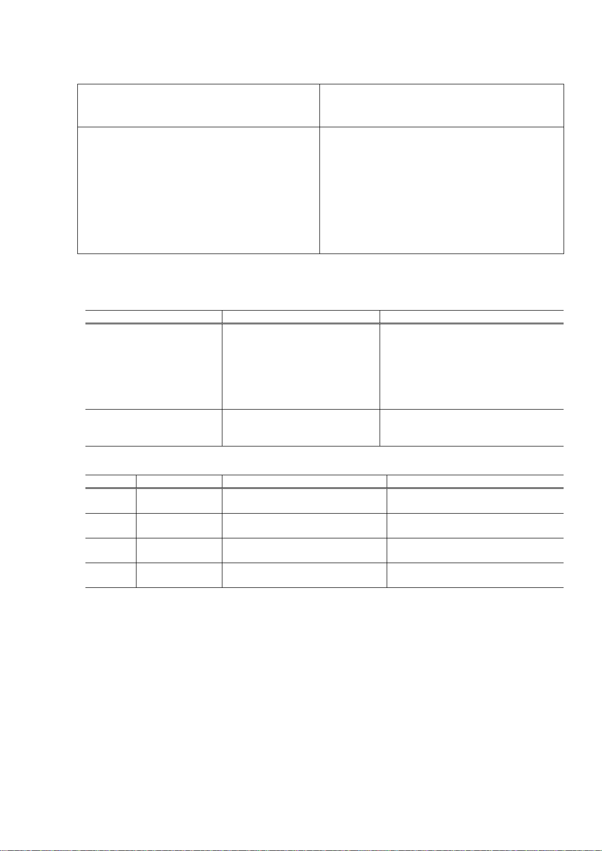
- Add the following error.
MP460 LCD MP180 LCD Error [Error
Solution Remarks
code]
The ink absorber is
almost full.
Press [OK] to
continue printing.
Contact the service
center.
REQ. SEVICE SOON Warning: The ink
absorber becomes
almost full.
[1700 for the main
ink absorber, 1710
for the platen ink
absorber]
Pressing the OK button
will clear the error, and
enable printing.
At repair:
For main ink absorber
replacement, replace
- the bottom case unit
(MP180: QM3-1362
MP460: QM3-1364),
or
- the ink absorber kit
(MP180: QY5-0149
MP460: QY5-0151)
For platen ink absorber
replacement, replace
- the platen ink absorber
(QC1-6014), and
- the ink absorber kit
(MP180: QY5-0149
MP460: QY5-0151)
The service call
error, indicating the
ink absorber is full,
is likely to occur
soon.
(2/2)
Page 3
2-1. Operator Call Errors
Error [Error code] Solution
Main ink absorber full [5B00]
Platen ink absorber full [5B10]
3. Repair
3-3. Adjustment / Settings
(7) Service mode
Function Procedures Remarks
Ink absorber counter reset See "Service mode operation
Ink absorber counter value
setting
<Service mode operation procedures>
Time(s) LED indication Function Remarks
4 times Green
(ON/OFF)
12 times Green
(ON/OFF)
13 times Orange (Alarm) Ink absorber counter value setting See "Ink absorber counter value
14 times
Return to the menu selection.
or more
(Replacement of listed parts, which are likely to
Main ink absorber:
- Bottom case unit
MP180: QM3-1362
MP460: QM3-1364
- Ink absorber kit
MP180: QY5-0149
MP460: QY5-0151
Platen ink absorber:
- Platen ink absorber (QC1-6014)
- Ink absorber kit
MP180: QY5-0149
MP460: QY5-0151
The main ink absorber counter and
procedures" below.
the platen ink absorber counter can be
reset separately.
If the value of the main ink absorber
counter is 7% or more, replace the
bottom case unit or ink absorber
(inside the bottom case unit).
See "Service mode operation
procedures" below.
The value can be set for the main ink
absorber counter and the platen ink
absorber counter separately.
Ink absorber counter reset
Button and LCD test
be faulty)
setting procedures" below.
(3/3)
Page 4

<Ink absorber counter resetting procedures>
1) In the ink absorber counter resetting mode, press the Stop/Reset button the specified number of
time(s) according to the ink absorber whose counter should be reset to 0%.
Time(s) LED indication Ink absorber
0 times Green
(ON/OFF)
1 time Orange (Alarm) Platen ink absorber
2 times Green
(ON/OFF)
Main ink absorber
Both the main and platen ink absorbers
<Ink absorber counter value setting procedures>
1) In the ink absorber counter value setting mode, press the Stop/Reset button the specified number
of time(s) according to the ink absorber whose value should be transferred to the EEPROM.
Time(s) LED indication Ink absorber
0 times Green
(ON/OFF)
1 time Orange (Alarm) Platen ink absorber
2 times Green
(ON/OFF)
3 times
or more
Orange (Alarm) Return to the ink absorber counter value setting mode
Main ink absorber
Both the main and platen ink absorbers
2) Press the ON/OFF button to proceed to the next step.
3) The ink absorber counter value can be set in 10% increments by pressing the Stop/Reset button.
Press the Stop/Reset button the appropriate number of time(s) to select the value which is
closest to the actual ink amount in the ink absorber.
Time(s) Ink absorber counter value to be set (%)
0 times 0%
1 time 10%
2 times 20%
3 times 30%
4 times 40%
5 times 50%
6 times 60%
7 times 70%
8 times 80%
9 times 90%
10 times
or more
Not valid.
Press the ON/OFF button to return to the ink absorber counter value setting mode.
4) Press the ON/OFF button to set the selected value to the EEPROM
3-4. Verification Items
(1) Service test print
<EEPROM information contents>
On the service test print (sample below), confirm the EEPROM information as shown below. (The
information is given in the upper portion of the printout.)
MPxxx M=Vxxx D=xxx.x USB(xxxxxx)
JPN JPN JPN JPN JPN JPN JPN
JPN JPN JPN JPN JPN JPN JPN
MPxxx: Model name
M=Vxxx: ROM version
D=xxx.x: Ink amount in the main ink absorber (%)
(4/4)
Page 5

USB(xxxxxx): USB serial number
JPN: Destination
<Print check items>
On the service test print (sample below), confirm the following items:
- Check 1, nozzle check pattern: Ink shall be ejected from all nozzles.
- Check 2, top of form accuracy: The lines shall not extend off the paper.
- Check 3, vertical straight line accuracy: The lines shall not be broken.
<Service test print sample>
Check 2: Top of form
Check 1: Nozzle check pattern
Check 3: Vertical straight line accuracy
(5/5)
Page 6

(2) EEPROM information print
<How to read EEPROM information print>
Print sample:
MP460 JPN V1.00 ST=2006/05/30-16:41 LPT=2006/07/04-10:25
ER(ER0=1000 ER1=5100) P_ON(S=00001) MSD(000)
IF(USB1=1) PC(M=000 R=000 T=011 D=000 C=000)
D=008.0 Ps 000.0
TPAGE(TTL=00022 COPY=00005)
CLT(2006/06/02-11:34)
CT(BK_ST=002 BK_HC=002 CL_ST=000 CL_HC=000)
IS(BK=0 M=0 C=0 Y=0)
IC(BK=02150 M=02435 C=02001 Y=02081)
A_REG=0 M_REG=1
CDIN(PB=000 OPB=000) BTIN=0
PAGE(All=00145 PP=00112 HR+MP=00000 PR+SP+SG=00033 GP=00000 PC=00000 EV=00000)
CDPAGE(All=00000)
EDGE=00000 L=00031 BTPAGE=00000
<Direct>
LG=01 Japanese CDI=000 CDP=000
CDD-PR (L=00020 2L=00000 PC=00000 A4=00000)
CDD-SP (L=00020 2L=00000 PC=00000 A4=00000)
CDD-MP (L=00020 2L=00000 PC=00000 A4=00000)
DCD-PP (L=00020 2L=00000 PC=00000 A4=00000)
DCD-FPP (L=00020 2L=00000 PC=00000 A4=00000)
DCD-MPP (L=00020 2L=00000 PC=00000 A4=00000)
PrnB=00000 SC=00000 Seal=00000
<Scanner>
SC=00000 SCAN_ER(ER0=0000 ER1=0000)
SC-dpi(75=00000 150=00000 300=00000 600=00000 1200=00000 2400=00000)
SG(GY=00000 CL=00000)
<Copy>
MCASF(PP=00000 SP+PR+GP=00000 OTH=00000)
CCASF(PP=00000 HR+MP=00000 PR+SP+SG=00000 GP=00000 PC=00000)
- EEPROM Information <Hex.> -
Printed items:
1: Model name (Destination)
2: ROM version
3: Installation date
4: Last printing time
5: Operator call / service call error record
6: Power-on count (soft-power-on)
7: Longest period of non-printing
8: I/F connection (USB1)
9: Purging count (M = manual cleaning, R = deep cleaning, T = timer cleaning, D = cleaning by dot
count, C = cleaning at ink cartridge replacement)
10: Ink amount in the ink absorber (D = main, Ps = platen)
11: Total print pages (TTL = total, COPY = number of copying sheets)
12: Last cleaning time
13: Ink cartridge replacement count (Black standard, black high capacity, color standard, color high
capacity)
14: Ink status (BK/M/C/Y)
(6/6)
Page 7

15: Total ink consumpt ion amount (BK/M/C/Y)
16: Half-automatic print head alignment on the machine
17: Manual print head alignment via the MP driver
18: Camera Direct print-supported device connection record (Canon PictBridge, other PictBridge)
19: Bluetooth-supported device connection record
20: Number of pages fed from ASF (total, plain paper, High Resolution Paper & Matte Photo Paper,
Photo Paper Pro & Photo Paper Plus Glossy & Photo Paper Plus Semi-gloss, Glossy Photo
Paper, Postcard, Envelope)
21: Camera Direct print pages in total
22: Borderless print pages
23: L & 4x6 print pages
24: Print pages via Bluetooth connection
<Direct>
25: Language setting
26: Number of times a memory card is inserted
27: Total Card Direct print pages
28: Memory Card Direct print pages: Photo Paper Pro (4x6, 5x7, postcard, A4/LTR)
29: Memory Card Direct print pages: Photo Paper Plus Glossy (4x6, 5x7, postcard, A4/LTR)
30: Memory Card Direct print pages: Matte Photo Paper (4x6, 5x7, postcard, A4/LTR)
31: Camera Direct print pages: Photo Paper (4x6, 5x7, postcard, A4/LTR)
32: Camera Direct print pages: Fast Photo Paper (4x6, 5x7, postcard, A4/LTR)
33: Camera Direct print pages: Matte Paper (4x6, 5x7, postcard, A4/LTR)
34: Print Beam pages fed
35: Business Card / Credit Card size paper pages fed
36: Sticker pages fed
<Scanner>
37: Total number of scanning
38: Scanning error status history
39: Number of scanning by the scanning resolution (75/150/300/600/1200/2400 dpi)
40: Number of scanning by the scanning tone (grayscale/color)
<Copy>
41: Number of monochrome copy pages fed from ASF (plain paper, Photo Paper Plus Glossy &
Photo Paper Pro & Photo Paper Plus Semi-gloss & Glossy Photo Paper, other paper)
42: Number of color copy pages fed from ASF (plain paper, High Resolution Paper & Matte Photo
Paper, Photo Paper Pro & Photo Paper Plus Glossy & Photo Paper Plus Semi-gloss, Glossy
Photo Paper, postcard)
- Printer EEPROM information dump in hex (Address 00h to FFh) –
(7/7)
Page 8

Part 3: APPENDIX
2. Connector Location and Pin Layout
2-1. Main Board
CN201 (IrDA) (MP460 only)
No. Signal name Function
1 S-GN Ground
2 IR RXD Receiving data signal
3 IR TXD Sending data signal
4 to 8 +3.3V Power supply
CN405 (Remote debugger)
No. Signal name Function
1 TXD Sending data signal
2 RXD Receiving data signal
3 GND Ground
4 +3.3V Power supply
(8/8)
Page 9

2-6. Carriage Board (Print Head Connector)
[Color print head]
No. Signal name Function
1 HENB2 Heat enable
2 HCLK Print head clock
3 B_HLAT Latch signal
4 B_DATA_C C serial data
5 B_DIA Diode sensor anode
6 to 11 GND Ground
12 to 15 --- Not used
16 ID4 Print head ID
17 to 22 VH Print head drive 24V
23 --- Not used
24 SGND Ground
25 DATA_M M serial data
26 VHT Power supply for power transistor inside the print head
27 VID Power supply for ID reading
28 B_HVDD Print head logic power supply
29 DATA_Y Y serial data
30 B_CNO Print head contact detection signal
31 B_HE1 Heat enable
[Black print head]
No. Signal name Function
1 SGND Ground
2 A_HCLK Print head clock
3 A_HLAT Latch signal
4 A_DATA_EVEN Even nozzle data
5 A_DIA Diode sensor anode
6 to 11 GND Ground
12 to 15 --- Not used
16 ID2 Print head ID
17 to 22 VH Print head drive 24V
23 --- Not used
24 SGND Ground
25 SGND Ground
26 A_VHT Power supply for power transistor inside the print head
27 A_VID Power supply for ID reading
28 A_HVDD Print head logic power supply
29 A_DATA_ODD Odd nozzle data
30 A_CNO Print head contact detection signal
31 A_HENB0 Heat enable
(9/9)
Page 10

3. Specifications
r
<Machine >
Throughput Approx. 52 sec. (PP-101 4x6, borderless printing, default settings)
For reference:
Custom 5 Standard
Black 22 ppm 13.7 ppm
Color 17 ppm 9.0 ppm
Print media
specifications
Acoustic noise level
(highest print quality)
Transparency CF-102 deleted.
- Printing from a computer: Approx. 44.5 dB
- Copying: Approx. 48.0 dB
<Copy>
Copy speed *1
Approx. 53 sec.
<Card Direct Printing>
Memory card drive Supported
memory card
Compact Flash TYPE I/II, Microdrive, SmartMedia Card,
Memory Stick, Memory Stick PRO, SD card, MultiMedia
Card (ver. 3.31), xD-Picture Card*, miniSD card*, Memory
Stick Duo*, Memory Stick PRO Duo*
Throughput *2 Approx. 67 sec. (MP460)
Approx. 66 sec. (MP180)
<Camera Direct Printing>
Supported digital
cameras
Digital cameras and digital video cameras supporting PictBridge
Throughput *3 Approx. 66 sec.
*1: Document copy speed is based on copying the manuscript "ISO/IEC FCD24712: Newsletter" (digital data printed
by offset) using default settings on plain paper.
Copy speed may vary depending on document complexity, copy mode, page coverage, type of paper used, etc.
and does not take into account warming up time.
*2: When printing a 6 megapixel image taken by certain Canon digital camera from a memory card on default
settings using Photo Paper Plus Glossy without border.
Actual print speed may vary depending on image data, print mode, type of paper and type of memory card
used.
*3: When printing a 6 megapixel image taken by certain Canon digital camera from PictBridge on default settings
using Photo Paper Plus Glossy without border.
Actual print speed may vary depending on image data, print mode, type of paper used and device that the printer
is connected to.
* Adapte
(10/10)
 Loading...