

Canon LBP-3260 Service Manual

SERVICE
MANUAL
REVISION 0
COPYRIGHT 1999 CANON INC. CANON LBP-3260 REV.0 JAN. 1999 PRINTED IN JAPAN (IMPRIME AU JAPON)
RY8-1390-000
JAN. 1999

COPYRIGHT © 1999 CANON INC
Printed in Japan
Imprimé au Japon
Use of this manual should be
strictly supervised to avoid
disclosure of confidential
information.
Prepared by
PERIPHERAL PRODUCTS QUALITY ADVANCEMENT DIV.
PERIPHERAL PRODUCTS TECHNICAL DOCUMENTATION DEPT.
CANON INC.
5-1, Hakusan 7-chome, Toride-City, Ibaraki-Pref. 302-8501, Japan

PREFACE
This Service Manual contains basic information required for after-sales service of the laser beam
printer LBP-3260 (hereinafter referred to as the "printer"). This information is vital to the service technician in maintaining the high print quality and performance of the printer.
This manual consists of the following chapters:
Chapter 1: Product information
Features, specifications, operation, and installation
Chapter 2: Operation and Timing
A description of the operating principles and timing sequences of the electrical and
mechanical systems.
Chapter 3: The Mechanical System
Explanation of mechanical operation, disassembly, reassembly and adjustment procedures
Chapter 4: Troubleshooting
Troubleshooting procedures, reference values and adjustments, maintenance and
servicing, etc.
Appendix: General timing chart, general circuit diagram, etc.
Information in this manual is subject to change as the product is improved or redesigned. All
relevant information in such cases will be supplied in the Service Information Bulletins.
A thorough understanding of this printer, based on information in this Manual and Service
Information bulletins, is required for maintaining its performance and for locating and repairing
the causes of malfunctions.

DTP system
This manual was produced on an Apple PowerMacintosh 9500/233 personal computer and output by an
Apple LaserWriter 16/600 PS laser beam printer; final pages were printed on DAINIPPON SCREEN MFG
CO. LTD DT-R3100.
All graphics were produced with Macromedia FreeHand (J), and all documents and page layouts were
created with QuarkXPress (E).
The video images were captured with SONY degital video camcorder and Radius PhotoDV capture board
system, and modified with Adobe Photoshop (J).

CONTENTS
CHAPTER 1 PRODUCT INFORMATION
I. FEATURES ............................ 1-1
II. SPECIFICATIONS .................. 1-3
III. SAFETY INFORMATION .... 1-6
IV. PARTS OF THE PRINTER ...... 1-7
V. INSTALLATION ...................... 1-9
VI. MAINTENANCE AND
SERVICING BY THE
CUSTOMER ........................... 1-18
VII. OPERATION .......................... 1-21
CHAPTER 2 OPERATION AND TIMING
CHAPTER 3 THE MECHANICAL SYSTEM
I. BASIC OPERATION................. 2-1
A. Functions.......................... 2-1
B. Basic Operation Sequences 2-2
C. Power On Sequence ........... 2-3
II. ENGINE CONTROL SYSTEM.... 2-4
A. DC Controller Circuit ........ 2-4
B. Fixing Control ................... 2-10
C. High-Voltage Power
Supply............................... 2-16
D. Power Supply..................... 2-19
E. Video Interface Control ..... 2-21
F. Other Controls .................. 2-23
III. LASER/SCANNER SYSTEM..... 2-26
A. Outline.............................. 2-26
B. Laser Control Circuit......... 2-27
C. Scanning System............... 2-30
IV. IMAGE FORMATION SYSTEM . 2-32
A. Outline.............................. 2-32
B. Printing Process ................ 2-34
V. PICK-UP/FEED SYSTEM......... 2-42
A. Outline.............................. 2-42
B. Paper Pick-up .................... 2-45
C. Fixing and Delivery Unit.... 2-57
D. Paper Jam Detection ......... 2-59
VI. OVERALL CONTROL SYSTEM. 2-61
A. Video Controller PCB......... 2-61
B. Control Panel .................... 2-65
C. Self Test............................ 2-66
I. PREFACE ............................... 3-1
II. EXTERNALS ........................... 3-2
A. Locations .......................... 3-2
B. Control Panel Unit............. 3-7
III. MAIN UNITS........................... 3-8
A. Laser/Scanner Unit ........... 3-8
B. Drive Unit ......................... 3-8
C. Pick-up Unit ...................... 3-9
D. Multi-purpose Tray Pick-up
Unit.................................. 3-12
E. Registration Roller Unit .... 3-12
F. Delivery Unit ..................... 3-13
G. Fixing Unit ........................ 3-13
H. Feed Unit .......................... 3-14
IV. MAIN PARTS .......................... 3-15
A. Locations .......................... 3-15
B. Multi-purpose Tray Pick-up
Roller ............................... 3-16
C. Separation Pad .................. 3-16
D. Pick-up/Feed/Separation
Rollers ............................. 3-17
E. Registration Lower Roller.. 3-17
F. Transfer Charging Roller ... 3-18
G. Fixing Roller Heater .......... 3-18
H. Fixing Upper Roller ........... 3-19
I. Fixing Lower Roller ........... 3-22
J. Cleaning Roller.................. 3-23
V. SWITCHES/SENSORS............. 3-24

A. Locations .......................... 3-24
B. Thermoswitch ................... 3-25
C. Door Switch ...................... 3-25
D. Upper Cassette Paper-size
Sensing Switch/Lower Cassette
Paper-size Sensing Switch . 3-26
E. Thermistor ........................ 3-26
F. Registration Paper Sensor . 3-27
G. Pick-up Unit Paper Sensor . 3-28
H. Pick-up Unit Door Sensor .. 3-28
I. Lower Cassette Sensor/
Upper Cassette Sensor/
Lower Cassette Paper-level
Sensor 1/Lower Cassette
Paper-level Sensor 2/Upper
Cassette Paper-level Sensor 1/
Upper Cassette Paper-level
Sensor 2/Lower Cassette
Paper-out Sensor/Upper
Cassette Paper-out Sensor. 3-29
J. Multi-purpose Tray Paper
Sensor /Lifting Plate
Position Sensor ................. 3-29
K. Face-down Tray Paper Full
Sensor /Face-down Tray
Delivery Sensor /Fixing
Unit Delivery Sensor ......... 3-30
VI. CLUTCHS/SOLENOIDS ........... 3-31
A. Locations .......................... 3-31
B. Multi-purpose Tray Pick-up
Clutch ............................... 3-32
C. Feed Clutch....................... 3-32
D. Registration Clutch ........... 3-33
E. Lifting Plate Solenoid ........ 3-33
F. Cassette Pick-up Solenoid . 3-34
G. Face-up Solenoid Unit ....... 3-34
VII. MOTORS/FANS ...................... 3-35
A. Locations .......................... 3-35
B. Main Motor........................ 3-36
C. Pick-up Motor.................... 3-36
D. Fans ................................. 3-37
VIII.PCBS...................................... 3-41
A. Locations .......................... 3-41
B. Video Controller PCB Unit . 3-42
C. DC Controller PCB ............ 3-43
D. Pick-up PCB ..................... 3-44
E. Multi-purpose Tray PCB ... 3-44
F. Switch/Sensor PCB .......... 3-45
G. High-voltage Power Supply
Unit .................................. 3-47
H. Cassette Paper-size Sensing
PCB .................................. 3-47
I. Power Supply ................... 3-48
I. PREFACE ............................... 4-1
A. Malfunction Diagnosis
Flowchart ......................... 4-1
B. Initial Check ..................... 4-4
C. Test Print.......................... 4-5
II. IMAGE DEFECTS.................... 4-8
III. PAPER JAMS
TROUBLESHOOTING .............. 4-14
IV. PAPER TRANSPORT
TROUBLESHOOTING .............. 4-18
V. MALFUNCTION
TROUBLESHOOTING .............. 4-20
VI. MALFUNCTION STATUS
TROUBLESHOOTING .............. 4-21
VII. MEASUREMENT AND
ADJUSTMENT ........................ 4-28
A. Mechanical Adjustment ..... 4-28
B. Electrical Adjustment........ 4-29
C. Variable Resistors, LEDs,
Test Pins, Jumpers and
Switches on PCBs.............. 4-30
VIII.MAINTENANCE AND
CHAPTER 4 TROUBLESHOOTING

APPENDIX
I. GENERAL TIMING CHART ...... A-1
II. GENERAL CIRCUIT DIAGRAM A-3
III. LIST OF SIGNALS................... A-5
IV. MESSAGES TABLE ................. A-11
SERVICING............................. 4-35
A. Periodic Replacement
Parts ................................ 4-35
B. Expected Service Life of
Consumable Parts.............. 4-35
C. Periodic Service ................ 4-35
D. Cleaning during a Service
Visit .................................. 4-36
E. Standard Tools .................. 4-38
F. Special Tools ..................... 4-39
G. Special Tools (printer driver
tester) Explanation........... 4-40
H. Solvents and Oil List ......... 4-47
IX. LOCATION OF CONNECTORS . 4-48


CHAPTER 1
PRODUCT INFORMATION
I. FEATURES ............................ 1-1
II. SPECIFICATIONS .................. 1-3
III. SAFETY INFORMATION .... 1-6
IV. PARTS OF THE PRINTER ...... 1-7
V. INSTALLATION ...................... 1-9
VI. MAINTENANCE AND
SERVICING BY THE
CUSTOMER ........................... 1-18
VII. OPERATION .......................... 1-21


I. FEATURES
1. High speed printing
Equipped with Motorola's PowerPC 603e, the printer is capable of printing about 32 pages per
minute (A4/Letter).
2. Superior print quality
Combination of high resolution printing at 600 DPI and the use of super fine toner offers clear
print images.
3. Duplex printing
With the optional duplexing unit installed, the printer can print on both sides of paper.
4. Continuous printing
With the optional paper deck installed in the printer in addition to the standard equipped multipurpose tray and upper and lower cassettes, up to about 3,100 sheets of paper (75g/m2) can be
loaded, enabling continuous printing in large volume.
5. 6-way paper pick-up
Optional 2x500 sheet paper deck and envelope feeder in addition to the standard equipped
multi-purpose tray and upper and lower cassettes offer 6-way paper pick-up. The printer can
change the paper pick-up source automatically according to the paper type in addition to the
paper size.
6. Delivery
With the optional staple stacker installed in addition to the standard face-down tray, up to 2,300
sheets of A4 or Letter size paper (75g/m2) can be delivered (simple stacking).
7. Various delivery methods
With the optional sorter attached to the printer, paper can be delivered in 4 modes: mail box, job
separator, stacker and collator.
8. Memory saving technology
Memory Reduction Technology accomplishes printing at 600 DPI with standard equipped memory (8 MB). It also decreases errors, such as memory over flow, and provides stable printing.
9. Energy saving/Toner saving
The printer cuts off the power to the fixing heater when it remains idle for a specified length of
time. It can also reduce toner consumption by selecting the economy mode to print light images
with less toner.
10.Automatic emulation switching
The printer supports Hewlett-Packard's enhanced PCL6. With the optional PostScript ROM
DIMM (Canon Translator Module A-72) installed, the printer can automatically switch between
the standard PCL and Adobe®PostScript®3™.
11.Automatic interface switching
In addition to the standard built-in bicentronics parallel port, optional interfaces can be
installed in the printer. The printer can automatically switch between the parallel and expansion interface according to which interface port the data sent from the host computer enters.
1 - 1
CHAPTER 1

This page intentionally left blank
1 - 2
CHAPTER 1

II. SPECIFICATIONS
A. Printer
1. Printer Engine
1) Type Desktop page printer (console type when paper deck is installed)
2) Printing method Electrophotography
3) Printing speed (Note 1) About 32 pages/min. (A4/Letter), about 18 pages/min. (A3)
4) First print time (Note 2) 12.9 sec. or less (A4), 14.3 sec. or less (A3)
5) Wait time (Note 3) 90 sec. or less
6) Resolution
Horizontal 600 DPI
Vertical 600 DPI
7) Image formation system
Laser Semiconductor laser
Scanning system Rotating six-faced prism mirror (Scanning mirror)
Photosensitive drum OPC
Charging Roller charging
Exposure Laser scanning
Toner Magnetic single-component dry toner
Development Toner projection development
Toner supply By EP-72 cartridge replacement (about 20,000 A4- or Letter-sized
prints; with "DENSITY" in "CONFIG MENU" set to "7" and 4% dot
density)
Transfer Roller transfer
Separation Curvature/discharge bias
Cleaning Blade
Fixing Heated rollers (600W, 450W)
8) Paper pick-up Multi-purpose tray
Cassette
Envelope feeder EF-9 (option)
2,000 Sheet paper deck PD-82 (option)
2x500 Sheet paper deck PD-82K (option)
Print paper Plain paper, colored paper, labels, OHT, envelopes, rough paper,
bond paper, tarnsparency paper, recycled paper, letterhead
Paper sizes
Multi-purpose tray Min. 98.4mm(W) × 190.5mm(L) to max. 297mm(W) × 432mm(L)
sized plain paper (64g/m2to 128g/m2recommended paper) and
paper mentioned above.
Upper cassette B4, A4, Legal, Letter-sized plain paper (64g/m2to 105g/m2rec-
ommended paper), and colored paper.
Lower cassette A3, B4, A4, Ledger, Legal, Letter-sized plain paper (64g/m2to
105g/m2recommended paper), and colored paper.
Multi-purpose tray
capacity 10mm stack (about 100 sheets of 75g/m2paper)
Cassette capacity 50mm stack (about 500 sheets of 75g/m2paper)
Cassette types
Upper cassette Universal (accommodates B4, A4, Legal, Letter sizes)
Lower cassette Universal (accommodates A3, B4, A4, Ledger, Legal, Letter sizes)
9) Print delivery Face-down/face-up
10) Print tray capacity
Face-down About 500 sheets (75g/m2paper)
Face-up About 100 sheets (75g/m
2
paper)
1 - 3
CHAPTER 1

11) Duplex print
Auto-duplexing When duplex unit (option) is installed, and plain paper (64g/m2to
105g/m2recommended paper) only.
Manual duplexing
(Note 4) Plain paper (64g/m2to 128g/m2recommended paper) on multi-
purpose tray only.
12) Environment
Temperature 10 to 32.5°C
Humidity 20 to 80%RH
Air pressure 760 to 1013hPa (560 ~ 760mmHg/equivalent to 0 ~ 2,600m above
the sea level)
13) Maximum power
consumption About 1,220W (20°C room temperature, rated voltage)
14) Noise level (Officially announced level based on ISO 9296)
Sound power level (1B=10dB) 6.9B or less (printing)
5.3B or less (standby)
Sound pressure level 54dB or less (printing)
(Bystander position) 38dB or less (standby)
15) Dimensions 566 (w) × 520 (D) × 540 (H) mm (excluding some projections)
16) Weight About 50kg (printer)
Aabout 3.4kg (cartridge)
17) Line voltage requirements
220 to 240V (-10%, +6%) 50/60Hz (±2Hz)
18) Options Duplex unit DU-82, envelope feeder EF-9, 2000 sheet paper deck
PD-82, 2x500 sheet paper deck PD-82K, sorter S-82, stapler
stacker SS-72
Notes: 1. A test print at room temperature of 20°C with rated voltage input.
2. When the printer is in READY state at a room temperature of 20°C, the time from
reception of the PRINT signal from the video controller until an A4 or A3-sized print
is delivered onto the face-down tray.
3. At a room temperature of 20°C with rated voltage input, the time from turning ON
the printer until the end of the WAIT period.
4. When manual duplexing, correct the curl of the print delivered in the face-down tray
before setting it in the multi-purpose tray.
2. Video Controller
1) CPU RISC processor: Motorola PowerPC 603e
2) RAM Standard: 8MB
Maximum: 40MB
3) ROM 4MB
4) ROM DIMM socket 2
5) RAM DIMM socket 3
6) Host interface Standard: IEEE 1284 compliant parallel
Option: expansion interface (Ethernet, Token Ring)
7) Language Standard: PCL 5e/PCL 6
Option: Adobe®PostScript®3™
8) Resident fonts 45 Scalable fonts (MicroType font), 8 Bitmap font
9) Optional fonts 136 fonts
10) Scaler UFST
1 - 4
CHAPTER 1

B. Option
1. Hard disk
1) Memory 2.16GB
2) Interface ATA-3 (IDE)
3) Dimensions 70 (w) × 12.7 (D) × 100 (H) mm (excluding mounting materials and
connector.)
4) Weight About 0.15kg
5) Power supply DC5V (supplied from the printer)
Specifications are subject to change with product modification.
1 - 5
CHAPTER 1

III. SAFETY INFORMATION
A. Laser Safety
An invisible laser beam is irradiated within the laser/scanner unit.
Since the laser beam can injure the eye if it strikes it, be sure not to disassemble the
laser/scanner unit. It cannot be adjusted in the field, anyway.
The label shown below is attached to the laser/scanner unit cover.
Figure 1-3-1
B. Toner Safety
Composed of plastic and minute colored components, toner is a non-poisonous substance.
If toner adheres to your skin or clothes, remove as much of it as possible with dry tissue
paper, then wash with cold water. If you use hot water, the toner will gel and become difficult
to remove.
As toner easily breaks down vinyl materials, avoid letting toner come into contact with vinyl.
C. Ozone Safety
An infinitesimal amount of ozone gas (O3) is generated during corona discharge from the charging roller used in this printer. The ozone gas is emitted only when the printer is operating.
This printer meets the ozone emission reference value set by Underwriters Laboratory (UL) at
the time it is shipped from the factory.
D. Power Supply Unit Safety
Care is needed as even though the printer switch may be OFF, there is a possibility that a current may still flow on the primary side. Be sure to remove the power plug before disassembly
and assembly of this printer.
1 - 6
CHAPTER 1
DANGERCAUTION
!
ATTENTION
VORSICHT
ATTENZIONE
PRECAUCION
VARO!
VARNING!
ADVARSEL!
ADVARSEL
RAYONNEMENT LASER INVISIBLE EN CAS D'O UVERTURE.
-
EXPOSITION DANGEREUSEAU FAISCEAU.
UNSICHTBARE LASERSTRAHLUNG.WENN ABDECKUNG GEÖFFNET.
-
NICHT DEM STRAHL AUSSETZEN.
RADIAZIONE LASER INVISIBILE IN CASO DI APERTURA.
-
EVITARE L'ESPOSIZIONE AL FASCIO.
RADIACION LASER INVISIBLE CUANDO SE ABRE.
-
EVITAR EXPONERSE AL RAYO.
AVATTAESSA OLET ALTTIINA NÄKYMÄTTÖMÄLLE
-
LASERSÄTEILYLLE. ÄLÄ KATSO SÄTEESEEN.
OSYNLIG LASERSTRÅLNING NAR DENNA DEL ÄR ÖPPNAD.
-
BETRAKTA EJ STRÅLEN.
USYNLIG LASER STRÅLING,NÅR DENNE ER ÅBEN.
-
UNDGÅ BESTRÅLING.
USYNLIG LASERSTRÅLING NÅR DEKSEL ÅPNES.
UNNGÅ EKSPONERING FOR STRÅLEN.
Invisible laser radiation when open.
AVOID DIRECT EXPOSURETO BEAM.
INVISIBLE LASER RADIATIONWHEN OPEN.
-
AVOID EXPOSURE TO BEAM.
-
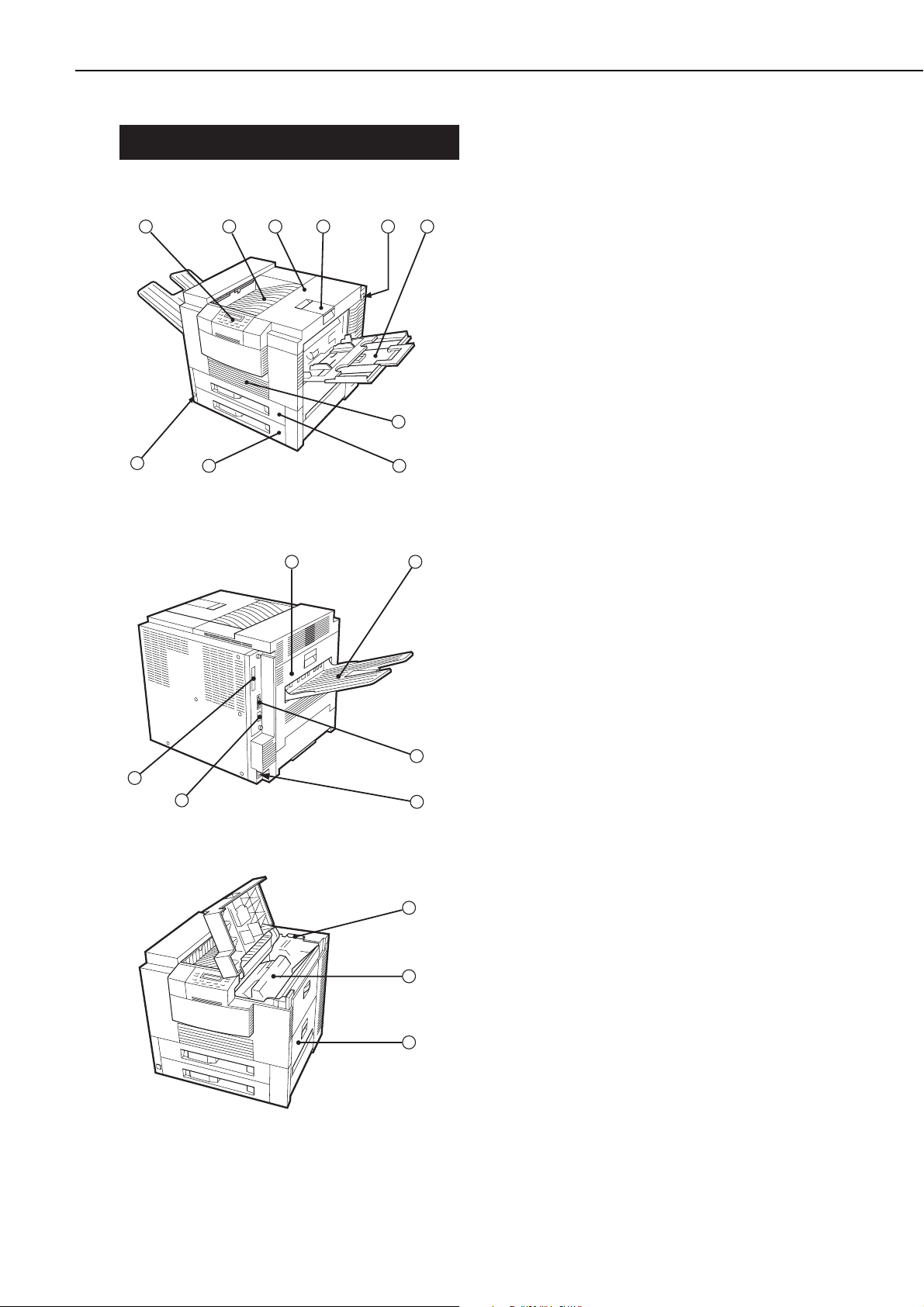
IV. PARTS OF THE PRINTER
A. External Views
Figure 1-4-1
Figure 1-4-2
Figure 1-4-3
1: Operation panel unit
2: Face-down tray
3: Upper cover
4: Delivery stopper
5: Test print switch
6: Multi-purpose tray
7: Duplex unit door
8: Upper cassette
9: Lower cassette
10: Power switch
11: Delivery cover
12: Face-up tray
13: Parallel interface connector
14: Power receptacle
15: Option interface connector (option)
16: Expansion board slot
17: Cleaning brush
18: EP-72 cartridge
19: Pick-up unit door
1 - 7
CHAPTER 1
123456
7
10
98
11
12
13
16
15
14
17
18
19
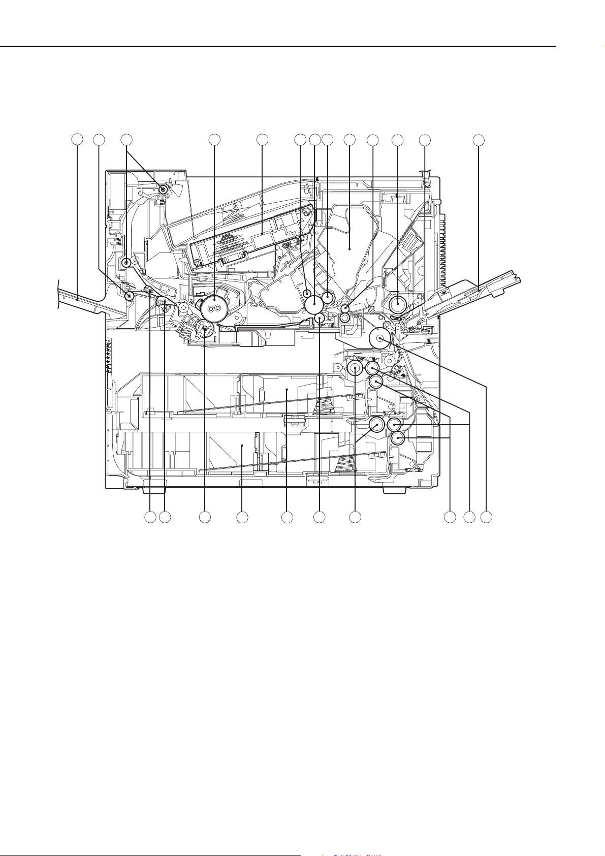
B. Cross-sectional Views
Figure 1-4-4
1: Face-up tray 13: Multi-purpose tray
2: Face-up delivery roller 14: Feed roller 1
3: Face-down delivery roller 15: Feed roller 2
4: Upper fixing roller 16: Separation roller
5: Laser/scanner unit 17: Pick-up roller
6: Primary charging roller 18: Transfer charging roller
7: Photosensitive drum 19: Upper cassette
8: Developing cylinder 20: Lower cassette
9: EP-72 cartridge 21: Lower fixing roller
10: Registration roller 22: Duplex deflector
11: Multi-purpose tray pick-up roller 23: Face-up deflector
12: Separation pad
1 - 8
CHAPTER 1
1
2 3 4 5 6 76 8 9
10 11
12 13
22
23
20
19
141516171821

V. INSTALLATION
A. Notes
This printer is packaged and shipped from the factory after careful adjustments and rigorous
inspections.
When installing the printer, it is important to demonstrate its performance in the same way as
when it passes the factory inspection.
The service engineer must sufficiently understand the performance of the printer, install it
correctly in a location with an appropriate environment, and conduct sufficient checks of the
unit.
B. Location Selection
Before taking the printer to the customer's premises, you should confirm the following conditions at the installation location.
1. Power supply
Use the following power supplies:
• Alternating current (AC): -10%, +6% of the rated voltage
• Power frequency: 50/60Hz±2Hz
2. Operating environment
Install in a location that meets the following conditions:
• Level, flat surface
• Temperature, humidity within the following ranges:
Surrounding temperature: 10to 32.5°C
Surrounding humidity: 20 to 80%RH (relative humidity), without condensation
• Cool, well-ventilated space
Do not install in the following locations:
• Exposed to direct sunlight
If you cannot avoid such a location, hang heavy curtains, etc. to shut out the direct sunlight.
• Near magnets and devices that emit a magnetic field.
• Areas with vibration
• Dusty places
• Near fire or water
3. Installation space
Install the printer a suitable distance from the wall, leaving enough room to operate it (see Figure
1-5-1).
When installing the printer on a desk, etc., be sure that it is large enough to accommodate
the printer's feet (rubber pads) and sturdy enough to hold its weight.
1 - 9
CHAPTER 1
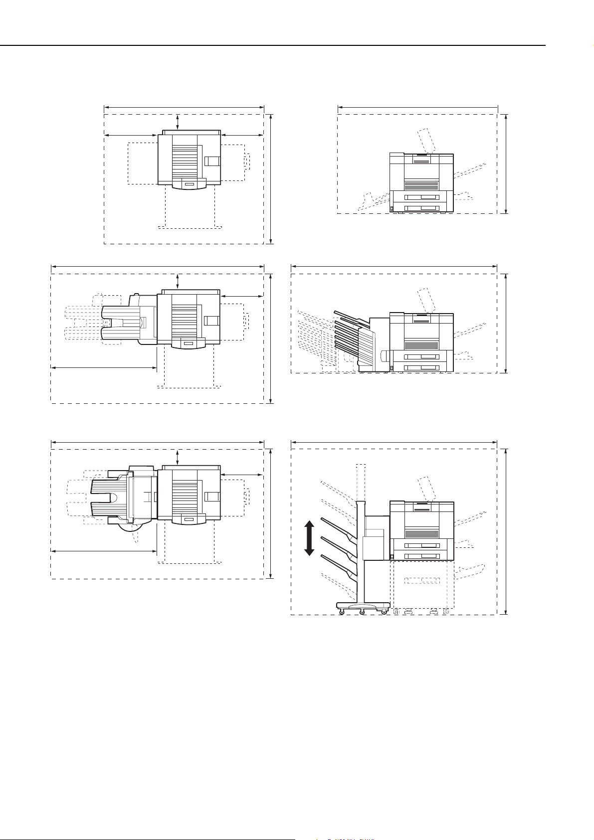
Figure 1-5-1
1 - 10
CHAPTER 1
900mm
1200mm
2600mm
2300mm
100mm
100mm
2300mm
834mm
900mm
1500mm
2600mm
834mm
900mm1380mm
1500mm1500mm
1200mm
2600mm
2600mm
100mm
834mm

C. Unpacking and Installation
Condensation will form on metal surfaces when brought into a warm room from the cold.
Therefore, when moving the printer to a warm environment, leave it packed in its box for at least
an hour to acclimatize to room temperature.
1. Printer
1) Open the printer packaging.
2) Take out the accessories. Confirm that the power cord, cartridge, and face-up tray are
included.
3) The printer weighs approx. 50kg, therefore 4 people may be needed to lift the printer and to
move to the installation area.
4) Take the plastic bag off the printer and peel the tape off each part. Check that none of the
covers were scratched or deformed during shipment.
5) Open the delivery cover, and remove the pressure release spacer from the fixing unit.
6) Open the upper cover, and remove the tape and the packing materials from inside the print-
er.
7) Pull the two cassettes out of the printer and remove the packaging from the cassette.
2. Cartridge
1) Open the bag holding the cartridge and take out the cartridge.
2) Remove the tape and the black sheet from the cartridge.
3) Hold the cartridge on each side as shown in figure 1-5-2 and slowly rock it 5 to 6 times to
evenly distribute the toner.
4) Place the cartridge on a flat surface. While holding down on the top of the cartridge with one
hand, grasp the tab with the other and gently pull out the sealing tape.
5) Open the upper cover of the printer, and load the cartridge with both hands. Slowly insert it
until it firmly contacts with the back of the slot.
3. Unpacking and installing the hard disk
Note: 1. Before handling the hard disk, be sure to touch the metal part of the printer to dis-
charge electrical static from you body in order to avoid causing damage to the PCB
by the difference in static charge at that time.
2. When removing the PCB at the back of the printer, be sure not to touch the electrical
parts on the PCB. Make sure not to touch especially the electrical elements.
1) Open the hard disk packaging.
2) Remove the pad and then take out the hard disk from its box.
3) Remove the plastic bag holding the hard disk.
4) If the optional expansion board is installed in the printer, remove the board.
5) Loosen the 2 screws at the left back of the printer and pull out the PCB.
1 - 11
CHAPTER 1
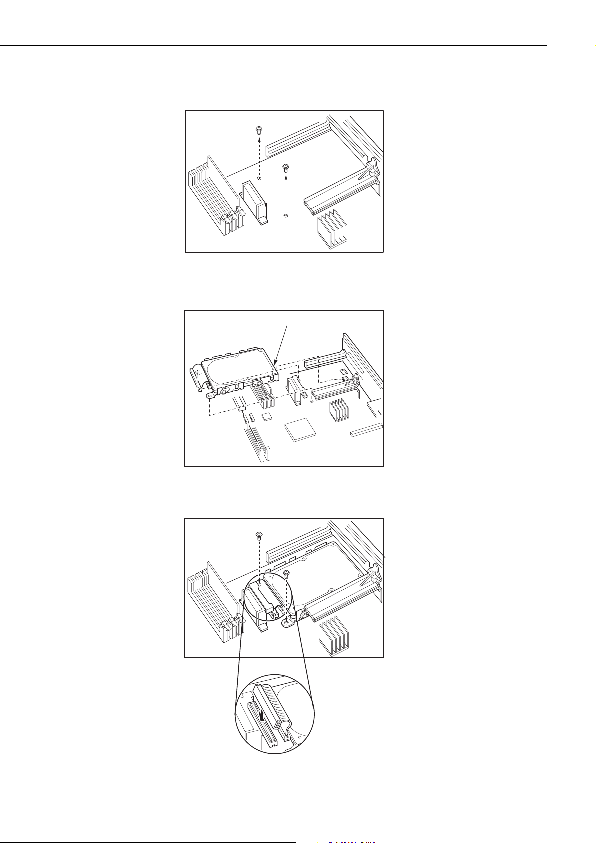
6) Remove the 2 screws on the PCB.
Figure 1-5-2
7) Insert the claw of the hard disk into the hole of the PCB.
Figure 1-5-3
8) Fix the hard disk with the enclosed 2 screws and then connect the connector.
Figure 1-5-4
1 - 12
CHAPTER 1
Hook
9) Install the PCB into the printer and fix it with 2 screws.
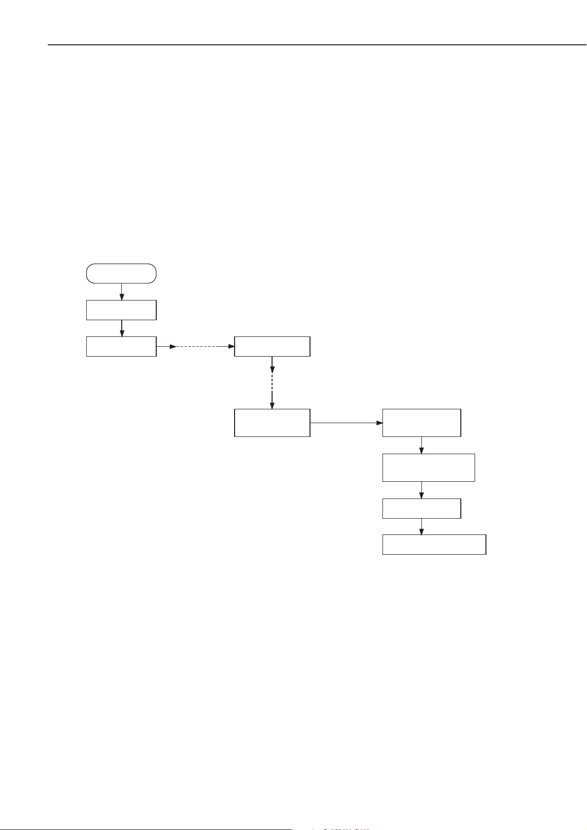
10) Turn ON the printer switch.
11) Press the On Line key when the printer becomes READY to take the printer off-line.
12) Press the Menu key to select "CONFIG MENU."
13) Press the Item key to select "FORMAT DISK."
14) Press the Enter key.
"+FORMAT DISK -IGNORE DISK" appears in the display.
15) Press the +Plus/-Minus key.
"+REALLY FORMAT -IGNORE DISK" appears in the display.
16) Press the +Plus/-Minus key.
"FORMATTING..." appears in the display, Disk LED lights up and formatting starts.
17) When the printer completes formatting the hard disk, "DISK FMT RESTART" appears in the
display, and the printer restarts automatically.
Figure 1-5-5
1 - 13
CHAPTER 1
Power On
READY
Press On Line key
PAUSED
Press Menu key
CONFIG MENU
Press Item key
CONFIG MENU
FORMAT DISK
Press Enter key
+FORMAT DISK
-IGNORE DISK
Press +Plus/-Minus key
+REALLY FORMAT
-IGNORE DISK
Press +Plus/-Minus key
FORMATTING...
DISK FMT RESTART

4. Operation confirmation
1) Load paper in the lower cassette.
2) Insert the power plug into the outlet and the printer, then turn the power switch ON.
After the printer enters STANDBY mode, press the test print switch to make a test print.
Check that the density of the output image is correct
3) Clean around the printer and ensure that it is ready for use at anytime.
5. Operation precautions
1) Turn ON the power of external equipment then the printer. Turn the power OFF in the
reverse sequence. If the power of external equipment is turned ON/OFF while the printer is
ON, noise may be transmitted through the connection cable between the external equipment
and the printer, and error may occur on the printer.
2) Turn off the power of both the printer and the external equipment before plugging/unplugging the connector between the two. Doing so while the power is ON could cause malfunctions.
1 - 14
CHAPTER 1
D. Storing, Handling the EP-72 Cartridge
Whether the cartridge is still sealed in its box or installed in the printer, the effect of the natural environment will change it over time regardless of the number of prints. As the progression of
this natural change depends on the storage or installation environment, take sufficient care in
storing and handling the cartridges.
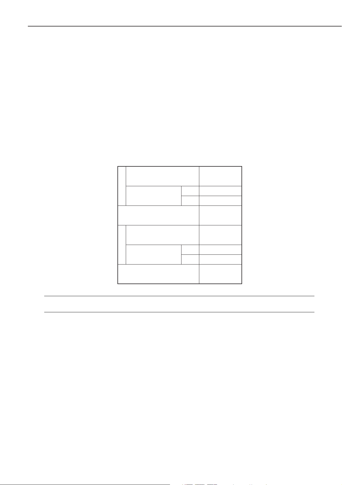
1. Before unsealing the box
When the cartridge is stored in a warehouse, workshop, etc., be sure to keep it within the ranges
shown in Table 1-5-1. Note the following points:
1) Avoid locations in direct sunlight.
2) Do not leave in areas exposed to strong vibration.
3) Do not bump or drop.
Table 1-5-1 Storage temperature and humidity conditions
Note: Total storage time is the valid time span following the manufacture date displayed on
the cartridge box.
2. After unsealing the box
As an organic photoconductor (OPC) is used in the photosensitive drum, it will deteriorate if
exposed to strong light. As there is toner in the cartridge, be sure to explain to the customer the
need to be careful in handling and storing unsealed cartridges.
a. Storage environment
1) Be sure to store in the aluminum bag.
2) Avoid locations exposed to direct sunlight, near windows, etc. Do not leave them in cars for
any extended period of time as heat can damage the cartridges.
3) Avoid high, low, and changeable temperature/humidity locations.
4) Avoid sites with corrosive gases (pesticides) or salt in the air.
5) Store the cartridge within a range of 0 to 35°C.
6) Do not leave cartridges near CRT displays, disk drives or floppy disks.
7) Store the cartridges out of reach of children.
1 - 15
CHAPTER 1
Normal (total storage time ×
9/10)
Severe (total storage
time × 1/10)
Temperature
Temperature change (within
3 minutes or so)
Normal (total storage time ×
9/10)
Severe (total storage
time 1/10)
Relative humidity
Air pressure
High
Low –20 to 0°C
High
Low
0to35°C
35 to 40°C
40°C→15°C
–20°C→25°C
35 to 85% RH
85 to 95% RH
10 to 35% RH
345 to 1013 hPa
(460 to 760 mmHg)

b. Effective life
Cartridges are effective for 2.5 years following the date of manufacture, which is displayed in an
abbreviated form on the cartridge. The cartridge life span is also displayed (month and year) on
the cartridge box as 2.5 years from the date of manufacture. Cartridges should be used within
their life spans, as image quality will deteriorate after the expiry date.
3. Handling
1) When loading a new cartridge into the printer, or when the toner in an already loaded cartridge hardens and blank spots appear on output images, hold the cartridge at each end as
shown in the below figure and slowly rock it about 45° in each direction 5 to 6 times. This
will evenly distribute the toner, and then reload it into the printer. Do not shake the cartridge
in any other way, as toner may leak from the developing cylinder or the cleaning unit.
Figure 1-5-6
To ensure that toner does not leak and dirty the images, be sure to print 3 to 5 pages of test
patterns after loading the cartridge in the printer.
2) When transporting the printer, remove the cartridges.
Either insert the cartridge in the aluminum bag or wrap it in a thick cloth to ensure light
does not penetrate it.
3) Do not leave the cartridge near CRT displays, disk drives, or floppy disks.
The magnetism generated by the cartridge may destroy their data.
4) As the photosensitive drum is sensitive to strong light, do not expose the cartridge to direct
sunlight or strong light (1500 lux or more). If it is exposed to strong light, blank spots or
black lines may appear on images.
Should this happen, temporarily turn OFF the printer. The distorted images such as blank
spots or black lines are likely to disappear. However, if the drum was exposed to strong light
for a long period of time, it is possible the black lines, etc., will remain.
5) Do not open the photosensitive drum protective shield by hand nor touch the drum surface.
Do not clean the drum.
6) Do not place the cartridge on its end or upside down. Always place it with the label side fac-
ing upward.
7) Do not disassemble the cartridge.
1 - 16
CHAPTER 1

Figure 1-5-7
1 - 17
CHAPTER 1
VI. MAINTENANCE AND SERVICING BY THE CUSTOMER
To maintain the optimum performance of the printer, the following maintenance should be performed by the customer.
1. Cartridge
Shake or replace the cartridge as the occasion demands.
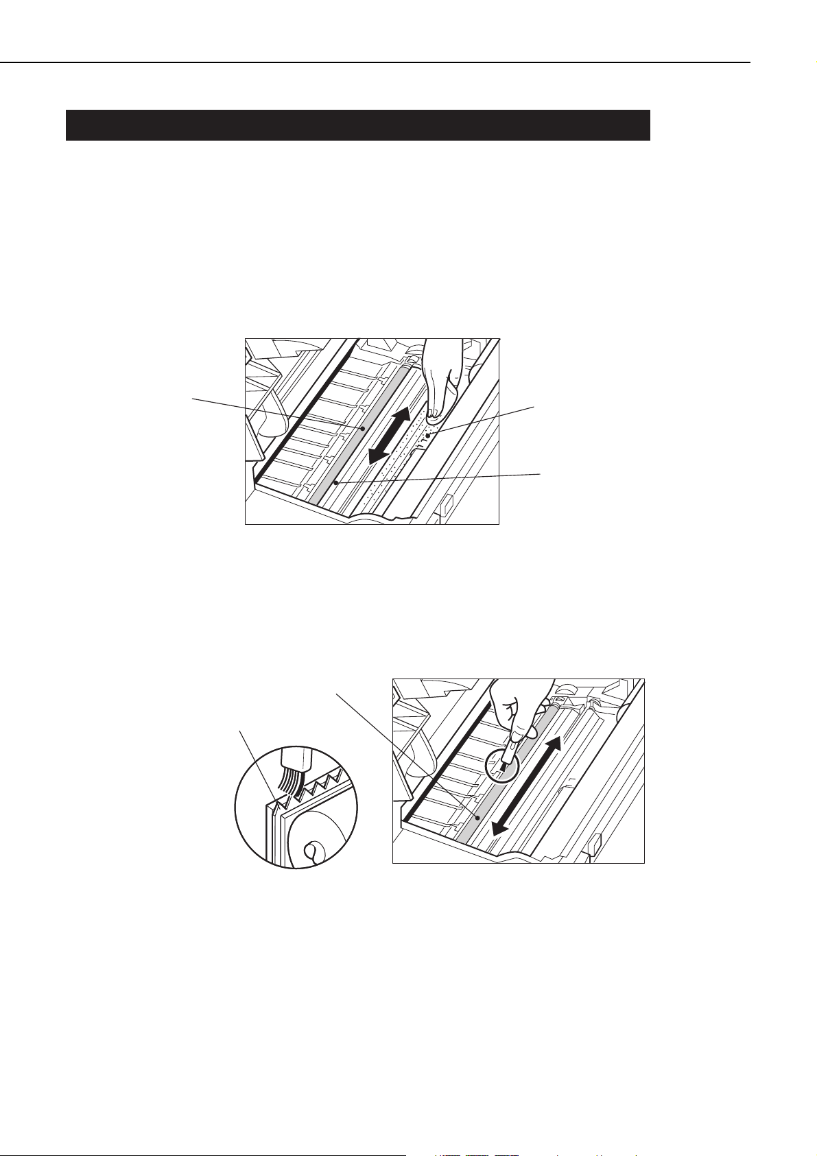
2. Transfer guide, registration guide
When replacing the cartridge, clean the transfer guide and registration guide with soft flannel
cloth.
Figure 1-6-1
3. Static charge eliminator
When replacing the cartridge, clean the static charge eliminator with the cleaning brush
attached inside the printer.
Figure 1-6-2
1 - 18
CHAPTER 1
Transfer chargin
roller
g
Registration guide
(metal part)
Transfer guide
(metal part)
Transfer charging roller
Static charge eliminator

4. Fixing unit
When replacing the cartridge, clean the fixing unit following the procedure below.
1) Open the multi-purpose tray and load one sheet of A4 or Letter size paper into the tray.
2) Press the On Line key to take the printer off-line.
3) Press the Menu key to select "PCL MENU."
4) Press the Item key to select "PAGESIZE."
5) Press the +Plus/-Minus key to select either A4 or Letter, and then press the Enter key.
6) Press the Menu key to select "FEEDER MENU."
7) Press the Item key to select "MPTSIZE."
8) Press the +Plus/-Minus key to select either A4 or Letter, and then press the Enter key.
9) Press the Menu key to select "TEST MENU."
10) Press the Item key to select "CLEANING PAGE" , and then press the Enter key. "LOAD PLAIN
A4 (or LETTER) IN MANUAL" will appear in the display and the Continue LED and Form Feed
LED will light up.
11) Press the Continue key to print the Cleaning Page. "LOAD BLANK SIDE UP IN MANUAL" will
appear and the Continue LED will light up.
Figure 1-6-3
1 - 19
CHAPTER 1
Load this sheet, thisside down, in MPT
Læg dette ark, meddenne side nedad, iuniversalbakke
Laad dit vel metdeze kant naar benedenin MPT
Lattaa tämä arkki, tämäpuoli alaspäin, MPT:hen
Introduire cette page, cecôté vers le bas,dans le tiroir polyvalent
Legen Sie dieses Blattmit dieser Seite nachunten in den MPTein
Caricare questa pagina, conquesta facciata verso ilbasso, nel MDT
Legg i arket meddenne siden ned iden manuelle materen
Coloque esta página, comeste lado para baixo,no MPT
Cargue esta hoja enMPT,conesta cara hacia abajo
Lägg detta ark medtextsidan nedåt på dinMPT
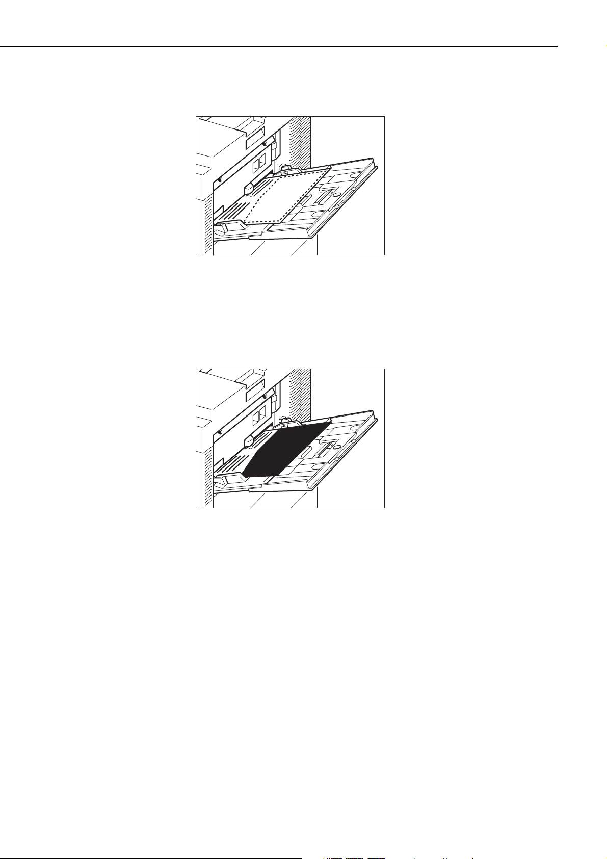
12) Place the printed Cleaning Page into the multi-purpose tray with the printed side face-down.
Figure 1-6-4
13) Press the Continue key to feed the Cleaning Page on the other side of the paper. "LOAD
CLEANING PAGE IN MANUAL" will appear and the Continue LED will light up.
14) Place the Cleaning Page into the multi-purpose tray.
Figure 1-6-5
15) Press the Continue key to feed the Cleaning Page through the printer to clean the fixing unit.
1 - 20
CHAPTER 1
 Loading...