

Canon DADF-M1 Service Manual

Aug 23 2007
Service Manual
Feeder
DADF-M1


Application
This manual has been issued by Canon Inc. for qualified persons to learn technical theory, installa tion, ma intenance, and repair
of products. This manual covers all localities where the products are sold. For this reason, there may be information in this
manual that does not apply to your locality.
Corrections
This manual may contain technical inaccuracies or typographical errors due to improvements or changes in products. When
changes occur in applicable products or in the contents of this manual, Canon will release technical information as the need
arises. In the event of major changes in the contents of this manual over a long or short period, Canon will issue a new edition
of this manual.
The following paragraph does not apply to any countries where such provisions are inconsistent with local law.
Trademarks
The product names and company names used in this manual are the registered trademarks of the individual companies.
Copyright
This manual is copyrighted with all rights reserved. Under the copyright laws, this manual may not be copied, reproduced or
translated into another language, in whole or in part, without the written consent of Canon Inc.
COPYRIGHT © 2001 CANON INC.
Printed in Japan
Caution
Use of this manual should be strictly supervised to avoid disclosure of confidential information.
Introduction
Symbols Used
This documentation uses the following symbols to indicate special information:
Symbol Description
Indicates an item of a non-specific nature, possibly classified as Note, Caution, or Warning.
Indicates an item requiring care to avoid electric shocks.
Indicates an item requiring care to avoid combustion (fire).
Indicates an item prohibiting disassembly to avoid electric shocks or problems.
Indicates an item requiring disconnection of the power plug from the electric outlet.
Indicates an item intended to provide notes assisting the understanding of the topic in question.
Indicates an item of reference assisting the understanding of the topic in question.
Provides a description of a service mode.
Provides a description of the nature of an error indication.
Memo
REF.

Introduction
The following rules apply throughout this Service Manual:
1. Each chapter contains sections explaining the purpose of specific functions and the relationship between electrical and mechanical systems with reference to the timing of operation.
In the diagrams, represents the path of mechanical drive; where a signal name accompanies the symbol , the arrow indicates the
direction of the electric signal.
The expression "turn on the power" m eans flipping on the power switch, closing the front door, and closing the delivery unit door, which results in
supplying the machine with power.
2. In the digital circuits, '1'is used to indicate that the voltage level of a given signal is "High", while '0' is used to indicate "Low".(The voltage value, however, differs from circuit to circuit.) In addition, the asterisk (*) as in "DRMD*" indicates that the DRMD signal goes on when '0'.
In practically all cases, the internal mechanisms of a microprocessor cannot be checked in the fi eld. Therefore, the operations of the microprocessors
used in the machines are not discussed: they are explained in terms of from sensors to the input of the DC controller PCB and from the output of the
DC controller PCB to the loads.
The descriptions in this Service Manual are subject to change without notice for product improvement or other purposes, and major changes will be communicated in the form of Service Information bulletins.
All service persons are expected to have a good understanding of the contents of this Service Manual and all relevant Service Information bulletins and be
able to identify and isolate faults in the machine."


Contents
Contents
Chapter 1 Specifications
1.1 Product Specifications................................................................................................................................1- 1
1.1.1 Specifications ........................................................................................................................................ ..................1- 1
1.2 Names of Parts............... .... ... ... .......................................... ... .... .................................................................1- 2
1.2.1 External View............................................................................................... .. ..........................................................1- 2
1.2.2 Cross Section..........................................................................................................................................................1- 2
1.3 Using the Machine......................................................................................................................................1- 3
1.3.1 Original Placement Indicator ............................................................................................................................... ....1- 3
1.3.2 Warning and Action to Take.................................................................................................................. ... ...............1- 3
Chapter 2 Functions
2.1 Basic Construction......................................................................................................................................2- 1
2.1.1 Overview of the Electrical Circuitry..........................................................................................................................2- 1
2.1.2 Inputs to the ADF Controller PCB............................................................................................................................2- 2
2.1.3 Outputs from the ADF Driver PCB...........................................................................................................................2- 3
2.2 Basic Operation..........................................................................................................................................2- 4
2.2.1 Routes of Drive ........................................................................................................................................................2- 4
2.2.2 Overview of Operation Modes.................................................................................................................................2- 4
2.2.3 Normal Rotation Pickup/Reversal Operation (single-sided original -> signal-side print).........................................2- 6
2.2.4 Normal Rotation Pickup/Delivery Operation (double-sided original -> double-sided print)......................................2- 7
2.2.5 Normal Rotation Pickup/Reversal Delivery (double-died original -> double-sided print).......................................2- 13
2.2.6 Idle Feed/Reversal Pickup/Delivery (single-sided original of mixed configurations -> single-sided print).............2- 15
2.3 Document Detection.................................................................................................................................2- 17
2.3.1 Overview................................................................................................................................................................2- 17
2.3.2 Checking the Presence/Absence of an Original....................................................................................................2- 18
2.3.3 Identifying the Size of the Original.........................................................................................................................2- 18
2.4 Document Pickup/Separation...................................................................................................................2- 24
2.4.1 Basic Sequence of Operation................................................................................................................................2- 24
2.4.2 Pickup Unit and the Stopper..................................................................................................................................2- 25
2.4.3 Timing of Pickup............................................................................................................. .......................................2- 25
2.4.4 Controlling the Pickup Motor (M1).........................................................................................................................2- 26
2.4.5 Controlling the Lock Motor (M4)............................................................................................................................2- 26
2.5 Document Reversing................................................................................................................................2- 27
2.5.1 Basic Sequence of Operation................................................................................................................................2- 27
2.5.2 Sequence of Operation..........................................................................................................................................2- 28
2.5.3 Controlling the Delivery Reversal Motor (M3).............................................................. ..........................................2- 28
2.6 Document Feeding/Delivery .....................................................................................................................2- 28
2.6.1 Basic Sequence of Operation................................................................................................................................2- 28
2.6.2 Sequence of Operation..........................................................................................................................................2- 29
2.6.3 Controlling the Feed Motor....................................................................................................................................2- 29
2.7 Detecting Jams............... .... ... ... ... .......................................... .... ... ... ... .... ... ...............................................2- 30
2.7.1 JAM .......................................................................................................................................................................2- 30
2.8 Power Supply ...........................................................................................................................................2- 30
2.8.1 Power Supply .................................................... .. ................................................... ... ............................................2- 30
2.9 Stamp Operation ................................... ... .... .......................................... ... ... ............................................2- 31
2.9.1 Overview................................................................................................................................................................2- 31
Chapter 3 Parts Replacement Procedure

Contents
3.1 Removing from the Host Machine..............................................................................................................3- 1
3.1.1 Feeder......................................................................................................................................................................3- 1
3.1.1.1 DADF-M1................................................................................................................................................................................. 3- 1
3.2 External Covers..........................................................................................................................................3- 1
3.2.1 Front Cover..................................................................................................................................... .........................3- 1
3.2.1.1 Removing the Front Cover.......................................................................................................................................................3- 1
3.2.2 Rear Cover........................................................................................................................ ... ....................................3- 2
3.2.2.1 Removing the Rear Cover ....................................................................................................................................................... 3- 2
3.2.3 Lower Left Cover........................................................................................................................ ... ...........................3- 2
3.2.3.1 Removing the Lower Left Cover .............................................................................................................................................. 3- 2
3.2.4 Feeder Cover................................................. ... .................................................. ... ..................................... ... ..........3- 2
3.2.4.1 Before Removing the Feeder Cover ........................................................................................................................................ 3- 2
3.2.4.2 Removing the Feeder Cover.................................................................................................................................................... 3- 2
3.2.5 Inside Cover (Upper).......................................................................................................................... ......................3- 2
3.2.5.1 Removing the Inside Cover...................................................................................................................................................... 3- 2
3.3 Drive System........................................ .......................................... ............................................................3- 2
3.3.1 Pickup Motor............................................................................................... ....................................... ......................3- 2
3.3.1.1 Before Removing the Pickup Motor ......................................................................................................................................... 3- 2
3.3.1.2 Removing the Pickup Motor..................................................................................................................................................... 3- 3
3.3.2 Feed Motor.................................... ... ................................................... ....................................... ... ...........................3- 3
3.3.2.1 Before Removing the Feed Motor............................................................................................................................................ 3- 3
3.3.2.2 Removing the Feed Motor ....................................................................................................................................................... 3- 3
3.3.3 Delivery Reversal Motor...........................................................................................................................................3- 3
3.3.3.1 Before Removing the Delivery Reversal Motor........................................................................................................................3- 3
3.3.3.2 Removing the Delivery Reversal Motor ...................................................................................................................................3- 3
3.3.4 Pressurization Motor................................................................................................................................................3- 4
3.3.4.1 Before Removing the Pressurization Motor ............................................................................................................................. 3- 4
3.3.4.2 Removing the Pressurization Motor......................................................................................................................................... 3- 4
3.3.5 Drive Unit................ ... ..............................................................................................................................................3- 4
3.3.5.1 Before Removing the Drive Unit ..............................................................................................................................................3- 4
3.3.5.2 Removing the Drive Unit..........................................................................................................................................................3- 4
3.4 Document Feeding System........................................................................................................................3- 5
3.4.1 Pickup Roller Unit ............................................. ... ..................................................... .......................................... .....3- 5
3.4.1.1 Before Removing the Pickup Roller Unit.................................................................................................................................. 3- 5
3.4.1.2 Removing the Pickup Roller Unit ............................................................................................................................................. 3- 5
3.4.2 Pickup Roller / Feed Roller................................................................................................................ ... ...................3- 5
3.4.2.1 Before Removing the Pickup Roller/Feeding Roller................................................................................................................. 3- 5
3.4.2.2 Removing the Pickup Roller/the Feeder Roller........................................................................................................................3- 5
3.4.3 Separation Plate/Separation Pad.............................................................................................................................3- 6
3.4.3.1 Before Removing the Separation Plate/Separation Pad.......................................................................................................... 3- 6
3.4.3.2 Removing the Separation Plate/Separation Pad ..................................................................................................................... 3- 6
3.4.3.3 Adjusting the Separation Pressure .......................................................................................................................................... 3- 6
3.4.4 No.1 Registration Roller Roll.......................................................................................................................... .. ........3- 6
3.4.4.1 Before Removing the No. 1 Registration Roller Roll................................................................................................................ 3- 6
3.4.4.2 Removing the No. 1 Registration Roller Roll ........................................................................................................................... 3- 6
3.4.5 No.1 Registration Roller................................................................... ....................................... .................................3- 7
3.4.5.1 Before Removing the No. 1 Registration Roller.......................................................................................................................3- 7
3.4.5.2 Removing the No. 1 Registration Roller................................................................................................................................... 3- 7
3.4.6 No.2 Registration Roller Roll.......................................................................................................................... .. ........3- 7
3.4.6.1 Before Removing the No. 2 Registration Roller Roll................................................................................................................ 3- 7
3.4.6.2 Removing the No. 2 Registration Roller Roll ........................................................................................................................... 3- 8
3.4.7 No.2 Registration Roller................................................................... ....................................... .................................3- 8
3.4.7.1 Before Removing the No. 2 Registration Roller.......................................................................................................................3- 8
3.4.7.2 Removing the No. 2 Registration Roller................................................................................................................................... 3- 8
3.4.8 Delivery Reversing Roller (upper)...................................................................................................... ... ...................3- 9
3.4.8.1 Before Removing the Delivery Reversal (upper) ..................................................................................................................... 3- 9
3.4.8.2 Removing the Delivery Reversal (upper).................................................................................................................................3- 9
3.4.9 Read Roller 1........................................................................................................................................ ...................3- 9
3.4.9.1 Before Removing the Feed Motor 1......................................................................................................................................... 3- 9

Contents
3.4.9.2 Removing the Read Roller 1.................................................................................................................................................... 3- 9
3.4.10 Platen Roller........................................................................................................................................................3- 12
3.4.10.1 Removing the Platen Roller .................................................................................................................................................3- 12
3.4.11 Platen Roller Roll Upstream ................................................................................................................................3- 12
3.4.11.1 Before Removing the Platen Roller Roll Upstream..............................................................................................................3- 12
3.4.11.2 Removing the Platen Roller Roll Upstream..........................................................................................................................3- 12
3.4.12 Platen Roller Roll Downstream............................................................................................................................3- 14
3.4.12.1 Removing the Platen Roller Roll Downstream.....................................................................................................................3- 14
3.4.13 Delivery Reversing Roller (lower)........................................................................................................................3- 14
3.4.13.1 Before Removing the Reversing Roller (lower).................................................................................................................... 3- 14
3.4.13.2 Removeing Delivery Reversing Roller (lower) ..................................................................................................................... 3- 14
3.4.14 Reversing Roller..................................................................................................................................................3- 15
3.4.14.1 Before Removing the Reversing Roller................................................................................................................................ 3- 15
3.4.14.2 Removing the Reversing Roller ...........................................................................................................................................3- 15
3.4.15 Reversion Roller Roll...........................................................................................................................................3- 16
3.4.15.1 Removing Reversing Roller Roll .......................................................................................................................................... 3- 16
3.4.16 Open/Close Guide Sheet.....................................................................................................................................3- 16
3.4.16.1 Removing the Open/Close Guide ........................................................................................................................................3- 16
3.4.16.2 Replacing the Open/Close Guide Sheet .............................................................................................................................. 3- 16
3.4.17 Duct-Collection Sheet............................................................ ..............................................................................3- 16
3.4.17.1 Replacing the Dust-Collecting Sheet ................................................................................................................................... 3- 16
3.5 Electrical System...................................... .... ... .......................................... ... ... .........................................3- 17
3.5.1 Fan ........................................................................................................................................................................3- 17
3.5.1.1 Before Removing the Cooling Fan......................................................................................................................................... 3- 17
3.5.1.2 Removing the Cooling Fan ....................................................................................................................................................3- 17
3.5.2 Document Width Volume....................................................................................................................................... 3- 17
3.5.2.1 Before Removing the Document Width volume.....................................................................................................................3- 17
3.5.2.2 Removing the Document Width volume................................................................................................................................. 3- 17
3.5.2.3 Mounting the Document Width Volume .................................................................................................................................3- 17
3.5.2.4 Adjusting the Side Guide Plate (slide guide) Position............................................................................................................ 3- 17
3.5.3 Pressurization Solenoid.........................................................................................................................................3- 18
3.5.3.1 Before Removing the Pressurization Solenoid ......................................................................................................................3- 18
3.5.3.2 Removing the Pressurization Solenoid..................................................................................................................................3- 18
3.5.4 ADF Driver PCB ....................................................................................................................................................3- 18
3.5.4.1 Before Removing the ADF Drover PCB................................................................................................................................. 3- 18
3.5.4.2 Removing the ADF Driver PCB.............................................................................................................................................. 3- 18
3.5.5 Separation Sensor.................................... .............................................................................................................3- 19
3.5.5.1 Before Removing the Separation Sensor ..............................................................................................................................3- 19
3.5.5.2 Removing the Separation Sensor..........................................................................................................................................3- 19
3.5.6 Read Sensor..........................................................................................................................................................3- 19
3.5.6.1 Before Removing the Read Sensor ....................................................................................................................................... 3- 19
3.5.6.2 Removing the Read Sensor................................................................................................................................................... 3- 19
3.5.7 Delivery Reversal Sensor...................................................................................................................................... 3- 20
3.5.7.1 Removing the Reversal Sensor ............................................................................................................................................. 3- 20
Chapter 4 Maintenance
4.1 User Maintenance ........................................ ... ... ... ... .... .......................................... ... ... ... ...........................4- 1
4.1.1 Cleaning ............................................................................................................................................. ... ..................4- 1
4.1.2 Replacement ......................................................................................................................................... ... .. .............4- 1
4.2 Maintenance and Inspection........ .... ... ... ... .... ... ... ... ... .... ... ... ... .....................................................................4- 2
4.2.1 Periodically Replaced Parts.....................................................................................................................................4- 2
4.2.1.1 Periodically Replaced Parts.....................................................................................................................................................4- 2
4.2.2 Durables................................................................................................................................................................. .4- 2
4.2.2.1 Durables...................................................................................................................................................................................4- 2
4.2.3 Periodical Servicing.................................................................................................................................................4- 2
4.2.3.1 Scheduled Servicing Chart ......................................................................................................................................................4- 2
4.2.4 Cleaning ............................................................................................................................................. ... ..................4- 4
4.2.4.1 Parts of the ADF ......................................................................................................................................................................4- 4

Contents
4.2.4.2 Rollers and Guides ..................................................................................................................................................................4- 5
4.2.4.3 Sensors.................................................................................................................................................................................... 4- 9
4.2.4.4 Applying Silicone Oil to the Reading Glass (copyboard glass)..............................................................................................4- 11
4.3 Adjustment ...............................................................................................................................................4- 13
4.3.1 Basic Adjustment...................................................................................................................................................4- 13
4.3.1.1 Overview................................................................................................................................................................................ 4- 13
4.3.1.2 Angle Guide (angle of opening at 90 deg) ............................................................................................................................. 4- 13
4.3.1.3 Sensor Output........................................................................................................................................................................ 4- 13
4.3.1.4 Tray Width............................................................... ............................................................................................................... 4- 13
4.3.1.5 Eliminating the Tilt..................................................................................................................................................................4- 13
4.3.1.6 Height..................................................................................................................................................................................... 4- 14
4.3.1.7 Right Angle ............................................................................................................................................................................4- 14
4.3.1.8 Angle Guide (angle of opening of 70 deg) ............................................................................................................................. 4- 15
4.3.1.9 Magnification.......................................................................................................................................................................... 4- 15
4.3.1.10 Horizontal Registration.................................................................................... .....................................................................4- 15
4.3.1.11 Leading Edge Registration................................................................................................................................................... 4- 16
4.3.1.12 White Level .......................................................................................................................................................................... 4- 17
4.3.1.13 Adjusting the Hinge Pressure............................................................................................................................................... 4- 17
4.3.2 Adjustment at Time of Parts Replacement............................................................................................................4- 17
4.3.2.1 Overview................................................................................................................................................................................ 4- 17
4.4 Outline of Electrical Components.............................................................................................................4- 17
4.4.1 Sensors..................................................................................................................................................................4- 17
4.4.2 Motors, Clutches, Solenoids, PCBs, and Others...................................................................................................4- 18
4.5 Variable Resistors (VR), Light-Emitting Diodes (LED), and Check Pins by PCB.....................................4- 19
4.5.1 Overview................................................................................................................................................................4- 19
4.5.2 ADF Driver PCB........................................................... ... .................................................. .....................................4- 19
4.5.3 Original Placement led PCB ..................................................................................................................................4- 19
Chapter 5 Error Code
5.1 Overview ....................................................................................................................................................5- 1
5.1.1 Overview..................................................................................................................................................................5- 1
5.1.2 Error Code ...................................................................................................................................... .........................5- 1
5.2 User Error Code ...................... ... ... ... .... ... ... ... .......................................... .... ... ... ... ... .... ... ............................5- 2
5.2.1 Alarm Code................................................................................................................................ ... ...........................5- 2

Chapter 1 Specifications


Contents
Contents
1.1 Product Specifications....................................................................................................................................................1-1
1.1.1 Specifications............................................................................................................................................................................... 1-1
1.2 Names of Parts...............................................................................................................................................................1-2
1.2.1 External View .............................................................................................................................................................................. 1-2
1.2.2 Cross Section ............................................................................................................................................................................... 1-2
1.3 Using the Machine.........................................................................................................................................................1-3
1.3.1 Original Placement Indicator ....................................................................................................................................................... 1-3
1.3.2 Warning and Action to Take........................................................................ ................................................................................ 1-3


Chapter 1
1-1
1.1 Product Specifications
1.1.1 Specifications
0002-7206
T-1-1
Item Description Remarks
Pickup method auto pickup/delivery
Original type sheet, book
Original weight Black-and-White
single-sided sheet:
AB: 42 to 128 g/m2
inch: 50 to 128 g/m2
double-sided sheet: 50 to 128 g/m2
If longer than 432 mm,
must be fed
individually: 60 to 90
g/m2
Color
64 to 128 g/m2
Black-and-While w/ Color
50 to 128 g/m2
Original size Size
B6, A5 (STMT) to A3 (11x17)
Note:
If B6, cross-feed
direction only.
Feed Direction
128.0 to 432.0 mm
(extra-length mode: 630 mm)
Cross-Feed Direction
139.7 to 297.0 mm
(304.8 mm max.)
Original placement Original Tray
face-up
Original orientation Original Tray
center reference
Original reading method stream reading
Original separation top separation
Original feed mode single-sided/double-sided
Original tray capacity 100 sheets (paper of 80 g/m2 or less)
if in excess of 80 g/m2, as appropriately converted
if folded, stack must be 13 mm or less in height
if in excess of 432 mm, single placement onlyif in
excess of 432 mm, single placement only
Original mix yes (mix of same configurations) Note:
Be sure to place
originals against the
rear end.
yes (mix of different configurations)
Combination of Configurations
AB: 13/B4, B4/A4R, A4/B5, B5/A5
Original size identification width: by pickup tray side guide platewidth: by
pickup tray side guide plate
length: by sensor and LGL sensor on tray
Residual original detection yes (in conjunction with host machine)
DONE stamp yes Note: optionally set (in
service mode).
Original processing speed single-sided: 50 ipm
double-sided: 25 ipm
high-speed double-sided (A4/LTR): 35 ipm
(default)
Communication with reader
unit
serial
Power supply 24 VDC, 13 VDC (from host machine)
Weight 14.7 kg (approx.)
Dimensions 575.5 (W) x 552.3 (D) x 151.2 (H) mm
Chapter 1
1-2
*1: To enable extra-length mode, use the following service mode item: COPIER>OPTION>USER>MF-LG-SET; to enable, select '1'; to disable, select '0',which
is the default.
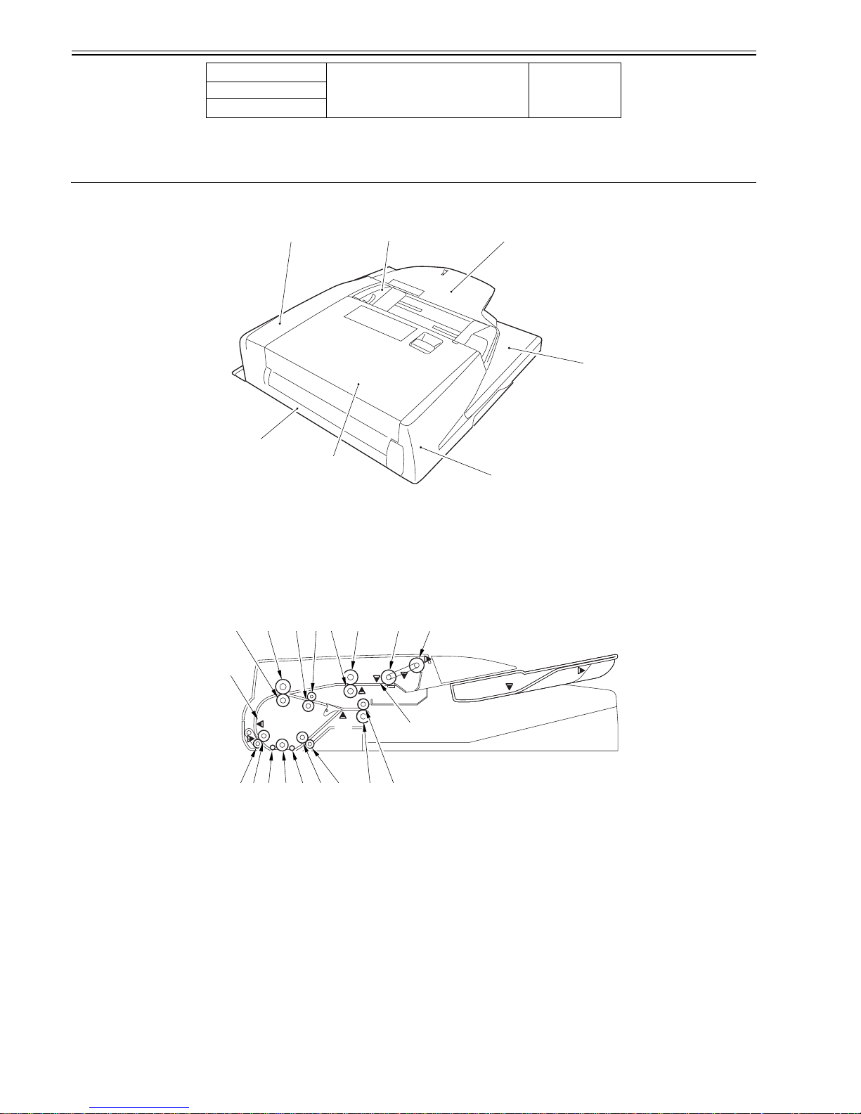
1.2 Names of Parts
1.2.1 External View
0002-7211
F-1-1
1 Feeder cover
2 Lower left cover
3 Rear cover
4 Slide guide
5 Original pickup tray
6 Original delivery assembly
7 Front cover
1.2.2 Cross Section
0002-7213
F-1-2
1 No. 2 registration roller, lower
2 No. 2 registration roller, upper
3 Reversing roller, lower
4 Reversing roller, upper
5 No. 1 registration roller, lower
6 No. 1 registration roller, upper
7 Separation roller
8 Pickup roller
9 Read roll 1
10 Read roller 1
11 Platen roll 1
12 Platen roller
13 Platen roll 2
14 Read roller 2
15 Read roll 2
16 Delivery reversing roller, lower
17 Delivery reversing roller, upper
Operating environment same as host machine
temperature
humidity
[1]
[2]
[3]
[4]
[5]
[6]
[7]
[1] [2] [3] [4][5] [6] [7] [8]
[9]
[10][11][12][13][14][15] [16] [17]
PI1
PI2
PI3
PI4
PI6
PI5
Read
Sensor
Separation
rear Sensor
PI9
Chapter 1
1-3
1.3 Using the Machine
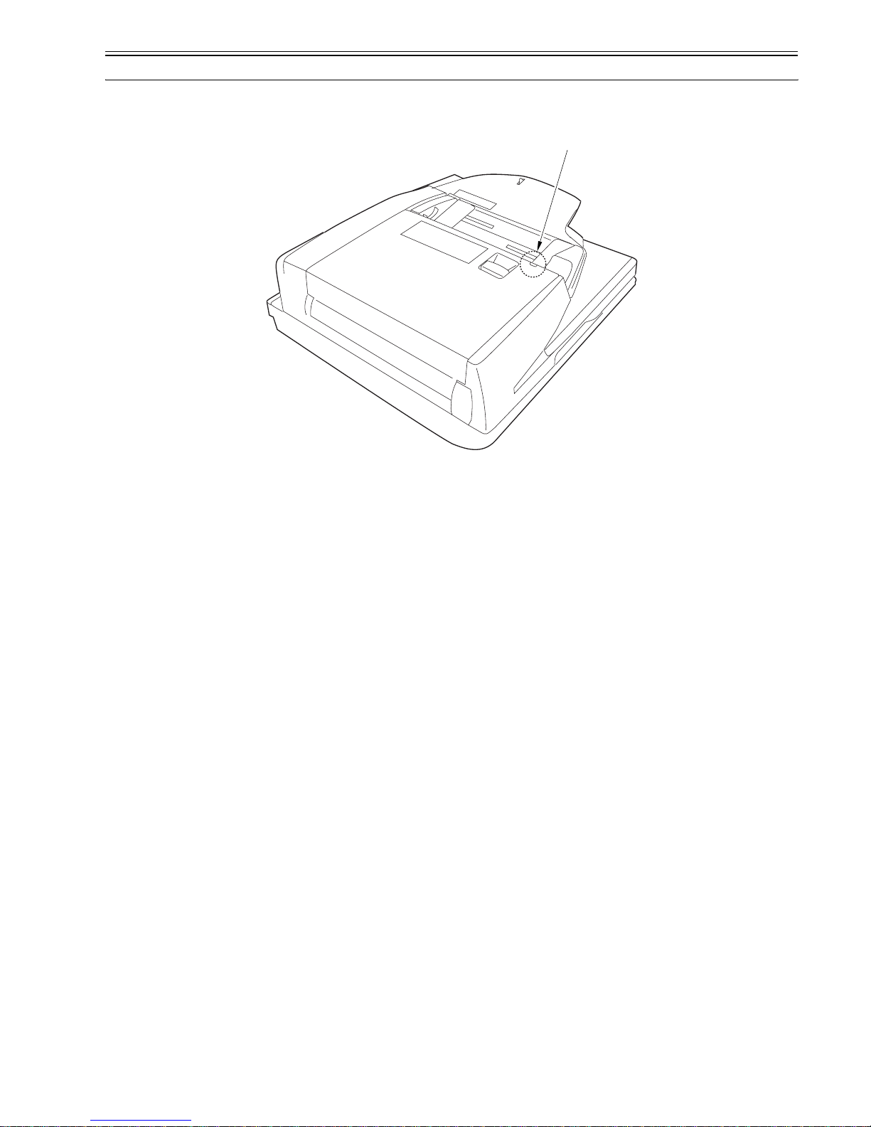
1.3.1 Original Placement Indicator
0002-7214
The original placement indicator goes on when an original is placed in the original tray, and it flashes to indicate the presence of a jam.
F-1-3
1.3.2 Warning and Action to Take
0002-7215
If the original placement indicator starts to flash while an original is being moved, suspect a jam, and go through the following:
1) Check all originals in the tray.
2) Open the feeder cover, and remove any jammed original.
3) Put the originals in order starting from 1st to last page, and place the stack back in the ADF.
Original placement indication


Chapter 2 Functions


Contents
Contents
2.1 Basic Construction.........................................................................................................................................................2-1
2.1.1 Overview of the Electrical Circuitry............................................................................................................................................ 2-1
2.1.2 Inputs to the ADF Controller PCB............................................................................................................................................... 2-2
2.1.3 Outputs from the ADF Driver PCB ............................................................................................................................................. 2-3
2.2 Basic Operation..............................................................................................................................................................2-4
2.2.1 Routes of Drive............................................................................................................................................................................ 2-4
2.2.2 Overview of Operation Modes..................................................................................................................................................... 2-4
2.2.3 Normal Rotation Pickup/Reversal Operation (single-sided original -> signal-side print) .......................................................... 2-6
2.2.4 Normal Rotation Pickup/Delivery Operation (double-sided original -> double-sided print)...................................................... 2-7
2.2.5 Normal Rotation Pickup/Reversal Delivery (double-died original -> double-sided print) ....................................................... 2-13
2.2.6 Idle Feed/Reversal Pickup/Delivery (single-sided original of mixed configurations -> single-sided print)............................. 2-15
2.3 Document Detection ....................................................................................................................................................2-17
2.3.1 Overview.................................................................................................................................................................................... 2-17
2.3.2 Checking the Presence/Absence of an Original......................................................................................................................... 2-18
2.3.3 Identifying the Size of the Original ........................................................................................................................................... 2-18
2.4 Document Pickup/Separation.......................................................................................................................................2-24
2.4.1 Basic Sequence of Operation ..................................................................................................................................................... 2-24
2.4.2 Pickup Unit and the Stopper...................................................................................................................................................... 2-25
2.4.3 Timing of Pickup ....................................................................................................................................................................... 2-25
2.4.4 Controlling the Pickup Motor (M1).............. .. ................................ ............................... .. .......................................................... 2-26
2.4.5 Controlling the Lock Motor (M4).............................................................................................................................................. 2-26
2.5 Document Reversing....................................................................................................................................................2-27
2.5.1 Basic Sequence of Operation ..................................................................................................................................................... 2-27
2.5.2 Sequence of Operation............................................................................................................................................................... 2-28
2.5.3 Controlling the Delivery Reversal Motor (M3) ......................................................................................................................... 2-28
2.6 Document Feeding/Delivery........................................................................................................................................2-28
2.6.1 Basic Sequence of Operation ..................................................................................................................................................... 2-28
2.6.2 Sequence of Operation............................................................................................................................................................... 2-29
2.6.3 Controlling the Feed Motor ....................................................................................................................................................... 2-29
2.7 Detecting Jams.............................................................................................................................................................2-30
2.7.1 JAM............................................................................................................................................................................................ 2-30
2.8 Power Supply...............................................................................................................................................................2-30
2.8.1 Power Supply............................................................................................................................................................................. 2-30
2.9 Stamp Operation ..........................................................................................................................................................2-31
2.9.1 Overview.................................................................................................................................................................................... 2-31

Chapter 2
2-1
2.1 Basic Construction
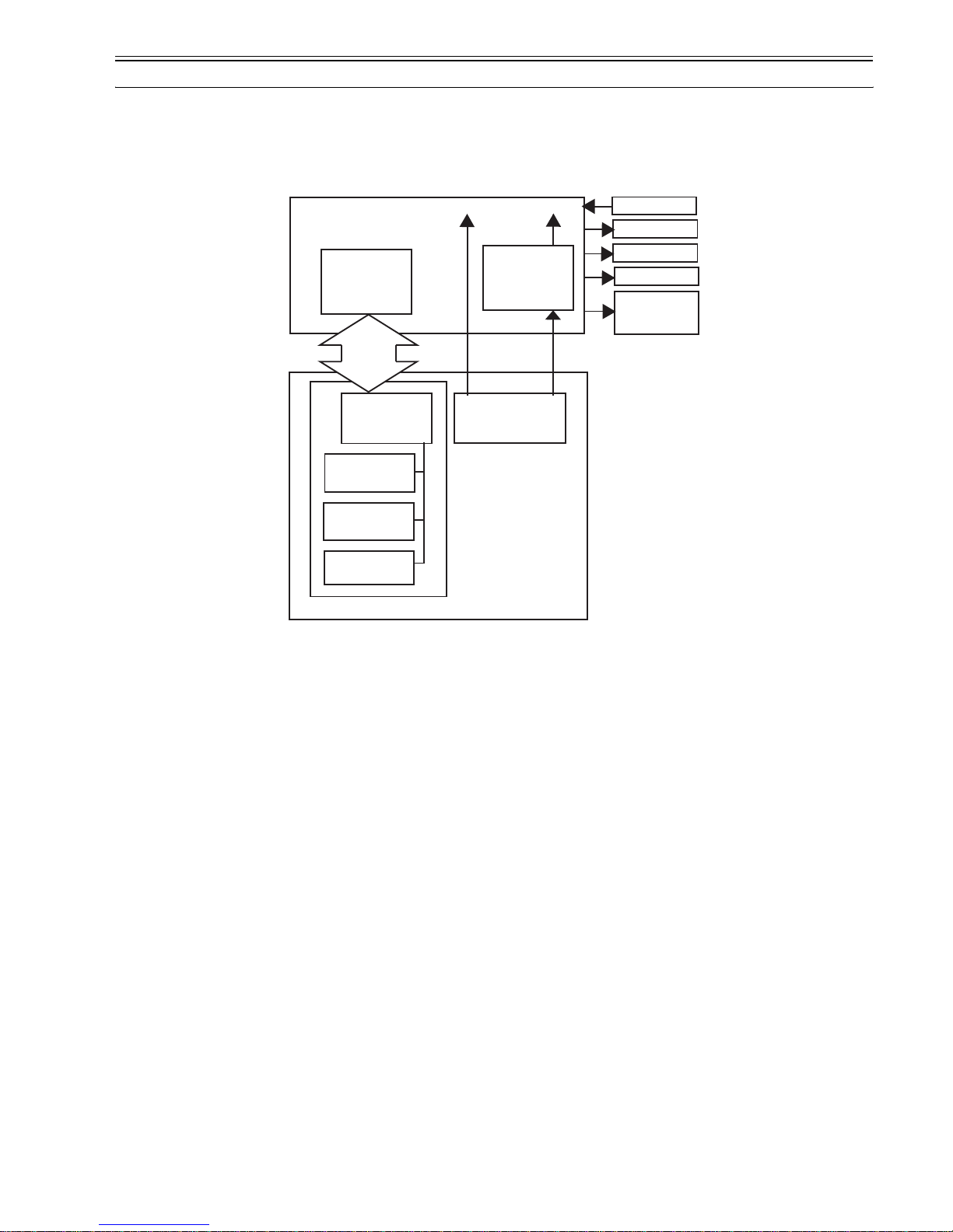
2.1.1 Overview of the Electrical Circuitry
0002-7181
The machine is not equipped with a controller PCB, and its electrical mechanisms are controlled by the reader controller PCB, which serves as a CPU (IC1). The
CPU interprets signals from sensors and the host machine to generate signals used to drive DC loads (e.g., motor, solenoid) with the help of the CPU (IC9) of the
ADF driver PCB.
F-2-1
ADF driver PCB
CPU
(IC9)
5 VDC
power supply
(IC10)
CPU
(IC1)
FLASH ROM
(IC3)
EEP ROM
(IC4,IC5)
IRC
(IC2)
Reader controller PCB
Power supply PCB
Sensor
Original
indication
LED PCB
Motor
Solenoid
Clutch
+13V
+24
+5
Host machine
Serial
communication
Chapter 2
2-2
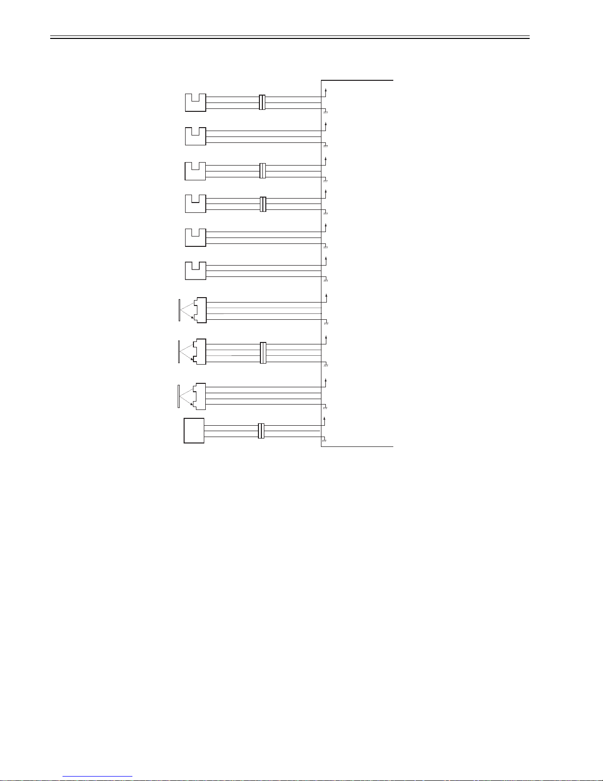
2.1.2 Inputs to the ADF Controller PCB
0002-7187
Inputs to the ADF Driver PCB (1/1)
F-2-2
+5V
ADF driver PCB
Registration
sensor
PI1
J14
1
3
2
J1401
3
1
2
REG_S
if paper is present, '1'.
+5V
Release HP
sensor
PI2
J1A
5
7
6
J102
3
1
2
RE_HP_S
+5V
Original
placement
sensor
PI5
J2
7
8
9
J203
3
2
1
EMP_S
+5V
Delivery
reversal
sensor
J1B
3
4
5
6
J112
4
3
2
1
HH_S_LED
HH_S
+5V
Read
sensor
J1A
1
2
3
4
J101
4
3
2
1
BNG_S_LED
+5V
Separation
rear sensor
J2
1
2
3
4
J3
3
2
1
J201
3
2
1
BNG_S
if paper is present, '0'.
(reference light intensity
adjustment signal)
J101
4
3
2
1
1
2
3
4
+5V
VR1
VR
detects original paper width.
(analog)
if paper is present, '0'.
(reference light intensity
adjustment signal)
if paper is present, 0'.
if paper is present, '0'.
(reference light intensity
adjustment signal)
Original
width
volume
3
1
3
1
3
2
J1401
+5V
LGL
sensor
PI4
J3
7
9
8
J312
3
1
2
LG_S
if paper is present, '1'.
(large size)
3
1
2
4
6
5
J302
+5V
AB/INCH
identification
sensor
PI3
J3
4
6
5
J311
3
1
2
A4LT_S
if paper is A4R/A5R, '1'
; if LTRR/STMTR, '0'.
6
4
5
1
3
2
J302
J301
1
2
3
3
2
1
+5V
ADF cover
open/closed
sensor
PI6
J2
10
11
12
J204
3
2
1
COVER_SH
READ_S_LED
READ_S
if feeder cover is closed, '1'.
if release motor is for lock, '1'
; for unlock, '1'.
Chapter 2
2-3
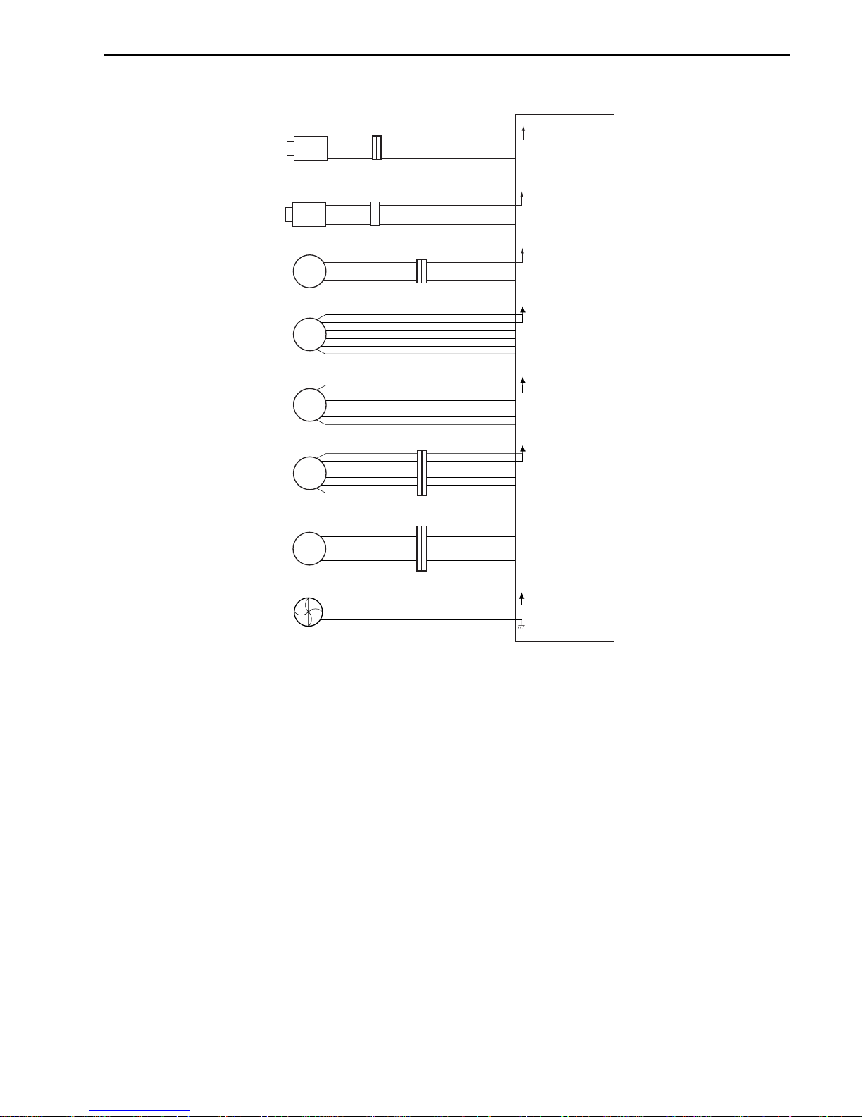
2.1.3 Outputs from the ADF Driver PCB
0002-7192
Outputs from the ADF Driver PCB (1/1)
F-2-3
Feed motor
J8
1
2
3
4
5
6
M2
OUTA
OUTA*
OUTB
OUTB*
+24V
Pickup clutch
+24V
J10
1
2
CLU when '1', CL1 goes ON.
CL1
J1001
211
2
Delivery
reversal motor
J10
3
4
7
8
6
5
M3
OUTA
OUTA*
OUTB
OUTB*
+24V
J1002
6
5
2
1
3
4
1
2
5
6
4
3
Pickup motor
J11
1
2
3
4
5
6
M1
OUTA
OUTA*
OUTB
OUTB*
+24V
1
2
FAN
J12
Cooling fan
FM1
Stamp
solenoid
SL1
+24V
J1B
2
1
STMP_SOL
when '1', SL1 goes ON
J111
122
1
Locking motor
J9
3
4
5
6
M4
OUTA
OUTA*
OUTB
OUTB*
J902
4
3
2
1
1
2
3
4
ADF driver PCB
Locking
solenoid
SL2
+24V
J9
1
2
R_SOL when '1', SL2 goes ON.
J901
211
2
Chapter 2
2-4
2.2 Basic Operation
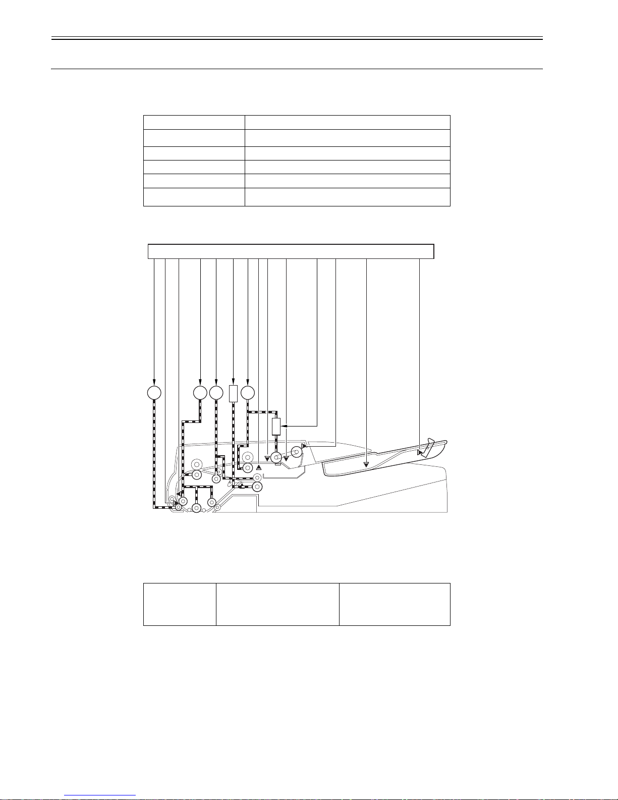
2.2.1 Routes of Drive
0002-7230
The machine is a document feeder exclusively designed for stream reading mode, and it uses 4 motors and 1 clutch to control the movement of originals.
T-2-1
The following is a diagram of the machine' s routes of drive:
F-2-4
2.2.2 Overview of Operation Modes
0002-7275
MEMO
The machine executes the following 4 types of operation mode, executing indivi d u al mo des according to the instructions from the host machine for printing. The
following table shows these operation modes, outlines of the modes, and corresponding printing modes:
T-2-2
Name Description
Pickup motor (M1) picks up/feed originals
Feed motor (M2) feeds originals.
Delivery reversal motor (M3) delivers or reverses originals.
Drive motor (M4) moves the read roll 1.
Pickup clutch (CL1) permits or cuts the drive from the pickup motor (M1) to the pickup roller and
the feed roller (drive system).
Operation mode Outline of operation Corresponding printing mode
M4
M2
SL2
CL1
M1
Original detection signal(RE_HP_S)
Original detection signal(READ_S)
J1A-7
J1A-3
J9-2
J14-3
J2-3
J2-9
J10-2
J2-12
J3-6
J3-9
Lock motor drive signal
Feed drive signal
Delivery reversal motor drive signal
Pressure solenoid drive signal(R_SOL)
Pickup motor drive signal
Pickup clutch drive signal(CLU)
Original placement signal(EMP_S)
AB/Inch identification signal(A4LT_S)
LGL identification signal(LG_S)
Registration original detection
signal(REG_S)
Original detection signal(BNG_S)
DF cover open/closed
detection signal(COVER_SH)
ADF driver PCB
M3

Chapter 2
2-5
MEMO
The machine executes idle rotation for a mix of sheets of the same configuration only if it identifies the paper in the tray at the beginning of the copy job as being
LGL.
A sheet of paper is identified as follows in terms of size:
small-size: B6, A5, A4, B5, LTR, STMT
large-size: A4R, B5R, A3, B4, LTRR, LGL, 279.4X431.8 mm (11x17)
1. Normal rotation
pickup/delivery
picks up an original, and delivers it after it has
been read.
single-sided original -> single-sided
print
single-sided original -> double-sided
print
extra-length original>single-sided print
2. Normal
rotation pickup/reversal
delivery
picks up an original, and reverses and
delivers it after it has been read.
double-sided original -> double-sided
print
double-sided original -> single-sided
print
3. Idle feed/reversal
pickup/reversal delivery
executes idle feed to find out the size of the
original; then, executes idle feed so that the
reading may start with the face of the
original; then, picks up, reverses, and delivers
it after it has been read.
double-sided original of different
configurations -> double-sided print
double-sided original of different
configurations -> single-sided print
double-sided original of same
configuration -> double-sided print
(inch-configuration only)
double-sided original of same
configuration -> single-sided prints
(inch-configuration only)
4. Idle feed/reversal
pickup/delivery
executes idle feed to identify the size of the
originals, reverses it, and delivers it after it
has been read.
single-sided original of different
configurations -> single-sided print
single-sided-original of different
configurations -> double-sided print
single-sided original of same
configuration -> double-sided print
(inch-configuration only)
single-sided original of same
configuration -> single-sided print (inchconfiguration only)
Chapter 2
2-6
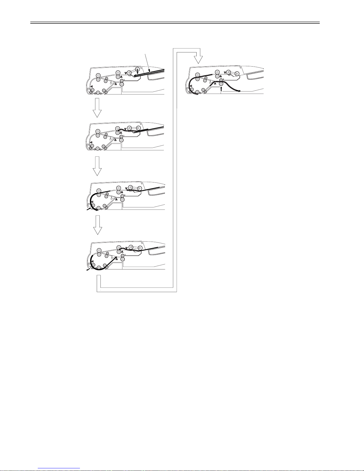
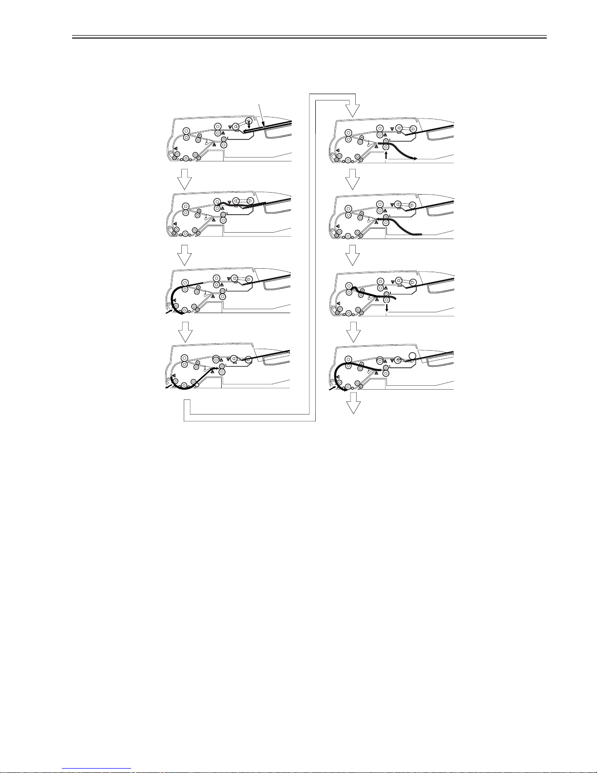
2.2.3 Normal Rotation Pickup/Reversal Operation (single-sided original -> signal-side print)
0002-7281
The following shows the flow of originals:
F-2-5
Original
Picking up the 1st sheet.
Arching the 1st sheet.
Standing by for reading
the 1st sheet.
Picking up the 2nd sheet.
Delivering the 1st sheet.
Reading the 2nd sheet.
Reading the 1st sheet.
Arching the 2nd sheet.
Chapter 2
2-7
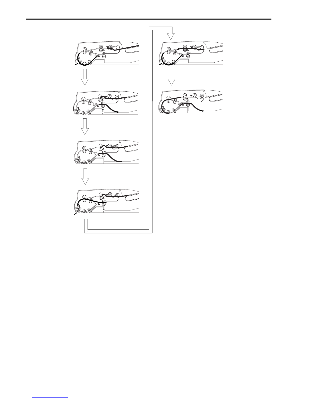
2.2.4 Normal Rotation Pickup/Delivery Operation (double-sided origi nal -> double-sided print)
0002-7298
The following shows the flow of originals:
1. Low speed double-sided mode
a. Small-Size
F-2-6
Standing by for reading
the 1st sheet.
Standing by for reading
the 1st sheet.
Reading the face of the
1st sheet.
Moving the 1st sheet.
Turning over the 1st sheet.
Arching the 1st sheet.
To next page
Picking up the 1st sheet.
Arching the 1st sheet.
Original
Chapter 2
2-8
F-2-7
Reading the back of the
1st sheet.
Picking up the 2nd sheet.
Moving the 1st sheet.
Arching the 2nd sheet.
Turning over the 1st sheet.
Moving the 1st sheet.
Idly moving the 1st sheet.
Moving the 2nd sheet.
Delivering the 1st sheet.
Reading the face of the 2nd sheet.
 Loading...