

Canon DADF-H1 Service Manual
DADF-H1
REVISION 0
MAR.2001
COPYRIGHT © 2001 CANON INC. 2001 CANON DADF-H1 REV. 0 MAR. 2001 PRINTED IN U.S.A.
FY8-13HA-000

Application
This manual has been issued by Canon Inc. for qualified persons to learn technical
theory, installation, maintenance, and repair of products. This manual covers all
localities where the products are sold. For this reason, there may be information in this
manual that does not apply to your locality.
Corrections
This manual may contain technical inaccuracies or typographical errors due to
improvements or changes in products. When changes occur in applicable products or in
the contents of this manual, Canon will release technical information as the need arises.
In the event of major changes in the contents of this manual over a long or short period,
Canon will issue a new edition of this manual.
The following paragraph does not apply to any countries where such provisions are
inconsistent with local law.
Trademarks
The product names and company names used in this manual are the registered
trademarks of the individual companies.
Copyright
This manual is copyrighted with all rights reserved. Under the copyright laws, this
manual may not be copied, reproduced or translated into another language, in whole or
in part, without the written consent of Canon Inc.
COPYRIGHT © 2001 CANON INC.
Printed in U.S.A.
Imprimé au U.S.A.
Caution
Use of this manual should be strictly supervised to avoid disclosure of confidential information.
COPYRIGHT © 2001 CANON INC. 20 CANON DADF-H1 REV. 0 MAR. 2001 PRINTED IN U.S.A.
INTRODUCTION
1 Symbols Used
This documentation uses the following symbols to indicate special information:
Symbol Description
Indicates an item of a non-specific nature, possibly classified as Note, Caution,
or W arning.
Indicates an item requiring care to avoid electric shocks.
Indicates an item requiring care to avoid combustion (fire).
Indicates an item prohibiting disassembly to avoid electric shocks or problems.
Indicates an item requiring disconnection of the power plug from the electric
outlet.
Indicates an item intended to provide notes assisting the understanding of the
Memo
topic in question.
REF.
COPYRIGHT
©
Indicates an item of reference assisting the understanding of the topic in question.
Provides a description of a service mode.
Provides a description of the nature of an error indication.
Refers to the Copier Basics Series for a better understanding of the contents.
2001 CANON INC. 2001 2001 2001 2001 CANON DADF-H1 REV.0 MAR. 2001
i

INTRODUCTION
2 Outline of the Manual
This Service Manual contains basic facts and figures needed to service the DADF-H1 in
the field, and it consists of the following chapters:
Chapter 1 General Description: features, specifications, methods of operation
Chapter 2 Outline of Operation: mechanical systems by function, electrical systems
in reference to principles of operation, timing of operation; construction and outline of electrical circuitry
Chapter 3 Mechanical Systems construction of mechanical systems; disassembly,
assembly, and adjustments
Chapter 4 Maintenance and Inspection:
periodically replacement parts, durables and
consumables; scheduled servicing chart
Chapter 5 Troubleshooting standards, adjustments, troubleshooting tables
Appendix: general timing chart, list of signals/abbreviations,
general circuit diagrams
For installation, refer to the Installation Procedure found in the shipping box; this manual
omits descriptions of the installation work.
ii
COPYRIGHT
©
2001 CANON INC. 2001 2001 2001 2001 CANON DADF-H1 REV.0 MAR. 2001

INTRODUCTION
The descriptions in this Service Manual are based on he following rules:
1. In each chapter, the uses of the function in question and its relationship to electrical and
mechanical systems are discussed and the timing of operation of its associated parts is
explained by means of outlines and diagrams.
In the diagrams, the symbol
represents a mechanical path, while the symbol
with a name next to it indicates the flow of an electric signal.
The expression “turn on the power” means turning on the power switch, closing the
front door, and closing the delivery door so that the machine will be supplied with
power.
2. In circuit diagrams (digital), a signal whose level is High is expressed as being ‘1’,
while a single whose level is Low is expressed as being ‘0’; the level of voltage, however, varies from circuit to circuit.
The machine uses CPUs, whose internal mechanisms cannot be checked in the field,
and, therefore, are not explained. In addition, the machine’s PCBs are not intended for
repairs at the user’s and, therefore, are explained by means of block diagrams: two types
are used, i.e., between sensors and inputs of PCBs equipped with a control or drive
function and between outputs equipped with a control or drive function and loads; in addition, functional block diagrams are used at times.
Changes made to the machine for product improvement are communicated in the form of
a Service Information bulletin as needed. All service persons are expected to go through all
service documentation including the bulletins and be equipped to respond to the needs of
the field (as by being able to identify possible causes of problems).
COPYRIGHT
©
2001 CANON INC. 2001 2001 2001 2001 CANON DADF-H1 REV.0 MAR. 2001
iii

CONTENTS
Contents
CHAPTER 1 GENERAL DESCRIPTION
1 Features...............................................1-1
2 Specifications...................................... 1-2
2.1 Specifications ............................. 1-2
3 Names of Parts .................................... 1-4
3.1 Exterior View ............................. 1-4
3.2 Cross-Sectional Vie w ................. 1-5
CHAPTER 2 OUTLINE OF OPERATION
4 Operation Descriptions ....................... 1-6
4.1 Document Set LED .................... 1-6
4.2 Alarm Indications and Corrective
Action......................................... 1-6
4.3 Daily Customer Checks ............. 1-7
1 Basic Configuration ............................ 2-1
1.1 Electrical Circuit Schematics .... 2-1
1.2 ADF Controller Circuit Board
Input ........................................... 2-2
1.3 ADF Controller Circuit Board
Output ........................................ 2-3
2 Basic Operations ................................. 2-4
2.1 Overview....................................2-4
2.2 Operations .................................. 2-6
2.2.1 Overview.............................. 2-6
2.2.2 Forwarding pickup/delivery
(Single-sided document ->
Single-sided print) ...............2-7
2.2.3 Forwarding pickup/reversal
delivery
(Double-sided document ->
Double-sided print).............. 2 -8
2.2.4 Idle feed/reversal pickup/
reversal delivery (Double-sided
documents of different sizes adhering to different systems ->
Double-sided print)............ 2-10
2.2.5 Idle feed/reversal pickup/delivery (Single-sided documents of
different sizes adhering to different systems -> Single-sided
print) .................................. 2-13
2.3 Document Set Detection .......... 2-15
2.3.1 Overview............................ 2-15
2.3.2 Detecting the presence or
absence of a document in the
document pickup tray ........ 2-17
2.3.3 Detecting whether the document
being fed is the last document
or not.................................. 2-18
2.3.4 Initial document size detection
(feed direction) .................. 2-19
2.3.5 Initial document size detection
(width direction) ................ 2-20
2.3.6 Final document size
detection ............................ 2-23
2.4 Document Pickup/Separation .. 2-26
2.4.1 Basic pickup operation ...... 2-26
2.4.2 Pickup station and stopper . 2-28
2.4.3 Pickup timing chart ........... 2-29
2.4.4 Pickup motor (M2)control. 2-30
2.5 Reversing .................................2-31
2.5.1 Operation ........................... 2-31
2.5.2 Operating sequences..........2-32
2.6 Document Feed/Delivery ......... 2-33
2.6.1 Operation ........................... 2-33
2.6.2 Operating sequence ........... 2-34
2.6.3 Feed motor (M1) control ... 2-35
3 Jams .................................................. 2-36
4 Power Supply.................................... 2-39
iv
COPYRIGHT
©
2001 CANON INC. 2001 2001 2001 2001 CANON DADF-H1 REV.0 MAR. 2001

CHAPTER 3 MECHANICAL SYSTEMS
CONTENTS
1 Basic Arrangement.............................. 3-1
1.1 Exterior Covers .......................... 3-1
1.1.1 Removing the ADF.............. 3-1
1.1.2 Detaching the front cover ....3-3
1.1.3 Detaching the rear cover ...... 3-3
1.1.4 Detaching the feeder cover .. 3-4
1.1.5 Removing the feed roller
guide .................................... 3-4
2 Drive Mechanism................................ 3-5
2.1 Pickup Motor ............................. 3-5
2.1.1 Releasing the pickup motor.3-5
2.1.2 Mounting the pickup motor. 3-6
2.2 Feed Motor................................. 3-7
2.2.1 Releasing the feed motor ..... 3-7
2.2.2 Mounting the feed motor..... 3-8
2.2.3 Disassembling the drive
mechanism ........................... 3-9
3 Feed System......................................3-12
3.1 Feeder Cover............................ 3-12
3.1.1 Releasing the pickup roller as-
sembly................................ 3-12
3.1.2 Removing the pickup roller/
separation roller ................. 3-12
3.1.3 Mounting the pickup roller as-
sembly................................ 3-13
3.1.4 Releasing the registration roller,
upper .................................. 3-14
3.2 Feed System............................. 3-15
3.2.1 Removing the separation plate/
separation pad .................... 3-15
3.2.2 Removing the feed station.3-16
3.2.3 Removing the delivery reversal
roller, upper ....................... 3-17
3.2.4 Removing read roller 2...... 3-18
3.2.5 Removing the platen roller 3-19
3.2.6 Removing read roller 1...... 3-20
3.2.7 Removing the registration roller,
lower .................................. 3-21
3.2.8 Adjusting platen guide L ... 3-23
3.2.9 Removing the delivery reversal
roller, lower........................ 3-24
3.2.10 Detaching read roller 2
roller .................................. 3-25
3.2.11 Replacing the separation
guide sheet ......................... 3-26
4 Electrical ........................................... 3-27
4.1 ADF Controller PCB ............... 3-27
4.1.1 Removing the ADF controller
circuit board ....................... 3-27
4.2 Feed Station Sensors................3-27
4.2.1 Removing the sensor
assembly ............................ 3-27
4.2.2 Removing sensors.............. 3-28
4.3 Document Pickup Tray Sensors3-28
4.3.1 Removing the document width
detection variable resistor .. 3-28
4.3.2 Installing the document width
detection variable resistor .. 3-29
4.4 Other Sensors and Solenoids ... 3-30
4.4.1 Removing the ADF open/closed
sensor switch ..................... 3-30
4.4.2 Removing the cover open/
closed sensor......................3-30
4.4.3 Removing the document set
sensor ................................. 3-30
4.4.4 Removing the locking
solenoid.............................. 3-31
COPYRIGHT
©
2001 CANON INC. 2001 2001 2001 2001 CANON DADF-H1 REV.0 MAR. 2001
v

CONTENTS
CHAPTER 4 MAINTENANCE AND INSPECTION
1 Parts Requiring Periodic
Replacement ....................................... 4-1
2 Expendable Parts Durability Table ..... 4 - 1
3 Periodic Service List........................... 4-2
4 Cleaning .............................................. 4-4
4.1 Reader Station Parts ................... 4-4
4.1.1 Document table glass........... 4-4
4.1.2 document table glass retainer4-4
4.2 ADF Parts .................................. 4-4
4.2.1 Platen guide ......................... 4-4
4.2.2 Blank plate (crimp plate) ..... 4-4
4.3 rollers and Guides ...................... 4- 5
4.3.1 Blank paper feed cleaning ... 4-5
4.3.2 Document pickup tray ......... 4-6
4.3.3 Pickup roller, separation
roller .................................... 4-6
4.3.4 Separation pad, separation
plate ..................................... 4-6
4.3.5 Registration roller, upper,
registration roller, lower,
separation guide...................4-7
4.3.6 Delivery reversal roller, upper,
delivery reversal roller,
lower .................................... 4-7
4.3.7 Reversal flapper ................... 4-8
5 Replacement ....................................... 4-9
5.1 Replacing the Feed Roller
Guide (Dust-collecting tape)...... 4-9
5.2 Replacing the Stamp ................ 4-10
6 Adjustment........................................ 4-11
6.1 Adjusting the Height................4-11
CHAPTER 5 TROUBLESHOOTING
1 Specifications and Adjustments .......... 5-1
1.1 Basic Adjustments...................... 5-1
1.1.1 Height adjustment................ 5-1
1.1.2 Squareness adjustment ......... 5-3
1.1.3 Scanning position
adjustment............................ 5-4
1.1.4 Horizontal registration
adjustment............................ 5-6
1.1.5 Scale adjustment.................. 5-9
1.1.6 Trailing registration
adjustment.......................... 5-13
1.2 Making Adjustments Following
Replacement of Key Parts........ 5-17
1.2.1 Overview............................ 5-17
1.2.2 Tray width detection variable
resistor adjustment mode ... 5-17
2 Troubleshooting................................ 5-19
2.1 Corrective Actions by Fault ..... 5-19
2.1.1 E420 lit .............................. 5-19
2.1.2 E421 lit .............................. 5-19
2.1.3 E422 lit .............................. 5-19
2.1.4 Black streaks appearing in a
printed image in the sub
scanning direction.............. 5-19
3 Electrical Parts Layout...................... 5-20
3.1 Sensors ..................................... 5-20
3.2 Motors, clutches, solenoids,
PCB, etc. ..................................5-21
4 LEDs, Check Pins, and Switches
by PCB.............................................. 5-22
4.1 ADF Controller PCB ............... 5-22
4.1.1 Component layout .............5-22
4.1.2 DIP switch function list.....5-23
4.2 Junction PCB ...........................5-26
4.3 Document Set LED PCB .........5-27
5 Self-Testing....................................... 5-28
5.1 Overview.................................. 5-28
5.2 Alarms......................................5-29
5.3 Jams ......................................... 5-29
5.4 Errors ....................................... 5-30
5.5 Host I/O Displays .................... 5-31
vi
COPYRIGHT
©
2001 CANON INC. 2001 2001 2001 2001 CANON DADF-H1 REV.0 MAR. 2001

APPENDIX
CONTENTS
1 General Timing Charts....................... A-1
1.1 Flow-Scanning a Single-sided A4
Document .................................. A-1
1.2 Scanning a Double-sided A4
Document, Face First,
Back Next.................................. A-2
2 Signal Name/Designation List........... A-3
3 General Block Diagram ..................... A-5
4 ADF Controller Block Diagram ........ A-6
5 Document Set Display Block
Diagram ........................................... A-11
6 Junction PCB Block Diagram ......... A-11
7 Jam Code List .................................. A-12
8 Special T ools List............................. A-13
9 Solvent/Grease List.......................... A-13
COPYRIGHT
©
2001 CANON INC. 2001 2001 2001 2001 CANON DADF-H1 REV.0 MAR. 2001
vii

CHAPTER 1
GENERAL DESCRIPTION
COPYRIGHT
©
2001 CANON INC. 2001 2001 2001 2001 CANON DADF-H1 REV.0 MAR. 2001

CHAPTER 1 GENERAL DESCRIPTION
1 Features
a. Flow scanning
Scanning is effected by flow scanning in all modes.
b. Document size recognition
The ADF recognizes document sizes in the length direction (feed direction) and in the
width direction and forwards the document size information to the host to which the ADF is
attached.
c.Double-sided document handling
Their reversal feature enables the ADF to handle double-sided documents.
d. Long-document mode
Long-document mode, when specified, allows the ADF to scan documents up to 630 mm
long.
e.Mixed loading of different sizes of documents adhering to different systems
The ADF supports mixed loading of documents of two different sizes.
* Mixed loading of documents of different sizes adhering to the AB and inch system is not
permitted.
COPYRIGHT
©
2001 CANON INC. 2000 2000 2000 2000 CANON DADF-H1 REV.0 MAR. 2001
1-1

CHAPTER 1 GENERAL DESCRIPTION
2 Specifications
2.1 Specifications
Item
Document pickup
method
Document set direction
Document set position
Document separation
method
Document type
Document size
Document tray loading
capacity
Document delivery station loading capacity
Document processing
mode
Document size recognition
Leftover document recognition
Mixed document loading feature
Book document
Specifications
Automatic pickup/delivery method
Document tray pickup: Face-up loading
Document tray pickup: Center standard
Top separation
Single-sided sheet document:
AB system 38 to 128 g/m
Inch system 50 to 128 g/m
Double-sided sheet document: 50 to 128 g/m
AB system
Inch system STMT/LTR/LTRR/LGL/11"x 17"
Document width: 148 (A5R) to 297 (A3) mm /
5.83 (A5R) to 11.69 (A3) in
Document length: 128 (STMT) to 432 (11" x
17") mm / 5.04 (STMT) to 17.01 (11 x 17) in
50 sheets
50 sheets
Single-sided and double-sided document handling
Yes (Standard sizes only)
Available in conjunction with the host
Mixed loading of documents of different sizes
adhering to the same system
Mixed loading of documents of different sizes
adhering to different systems
• Mixes of document sizes adhering to different
systems available for loading
AB system A3/B4 A4/B5 B4/A4R B5/A5
Handled (documents up to 50 mm / 1.97 in in
thickness only)
B6/A5/B5/A4/A5R/A4R/B4/A3
2
2
Remarks
60 to 90 g/m2 for documents longer than 432
mm / 17.01 in
2
Single-sided documents up
to 630 mm / 24.80 in long
available for scanning in
long-document mode
With paper weighing 80
g/m2 or lighter
With paper weighing 80
g/m2 or lighter
With paper weighing 80
g/m2 or lighter
With paper weighing 80
g/m2 or lighter
1-2
COPYRIGHT
©
T01-201-01
2001 CANON INC. 2000 2000 2000 2000 CANON DADF-H1 REV.0 MAR. 2001

CHAPTER 1 GENERAL DESCRIPTION
Item
Communication with the
host
Input power requirement
Mass
Physical dimensions
Unit addresses
Operating environment
Temperature range
Humidity range
Specifications and other information are subject to change without notice.
Specifications
IPC Communication 2.1
DC24VSupplied from the host to which the
ADF is attached.
Approx. 14 kg / 30.8 lb
565 (width) x 538 (depth) x 124 (height) mm /
22.24 (width) x 21.18 (depth) x 4.88 (height) in
A-system: XDDxxxxx
Inch/A-system: XDCxxxxx
AB system: XDBxxxxx
Inch/AB system: XDExxxxx
Conforming to the host.
Conforming to the host.
T01-201-02
Remarks
COPYRIGHT
©
2001 CANON INC. 2000 2000 2000 2000 CANON DADF-H1 REV.0 MAR. 2001
1-3
CHAPTER 1 GENERAL DESCRIPTION
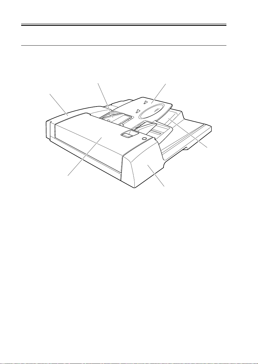
3 Names of Parts
3.1 Exterior View
[2]
[1]
[1] Feeder cover
[2] Rear co ver
[3] Slide guide
[3]
[4]
[6]
[5]
F01-301-01
[4] Document pickup tray
[5] Front cover
[6] Document delivery station
1-4
COPYRIGHT
©
2001 CANON INC. 2000 2000 2000 2000 CANON DADF-H1 REV.0 MAR. 2001
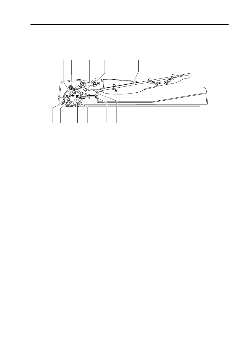
3.2 Cross-Sectional View
CHAPTER 1 GENERAL DESCRIPTION
[1] [2] [3]
[11]
[12][13][14]
[4]
[10]
[5] [6]
[9]
[1] Registration roller, lower
[2] Registration roller, upper
[3] Separation roller
[4] Separation pad
[5] Separation plate
[6] Pickup roller
[7] Document pickup tray
[7]
[8]
F01-302-01
[8] Delivery reversal roller, upper
[9] Delivery reversal roller, lower
[10] Read roller 2 roller
[11] Read roller 2
[12] Platen roller
[13] Read roller 1 roller
[14] Read roller 1
COPYRIGHT
©
2001 CANON INC. 2000 2000 2000 2000 CANON DADF-H1 REV.0 MAR. 2001
1-5
CHAPTER 1 GENERAL DESCRIPTION
4.Operation Descriptions
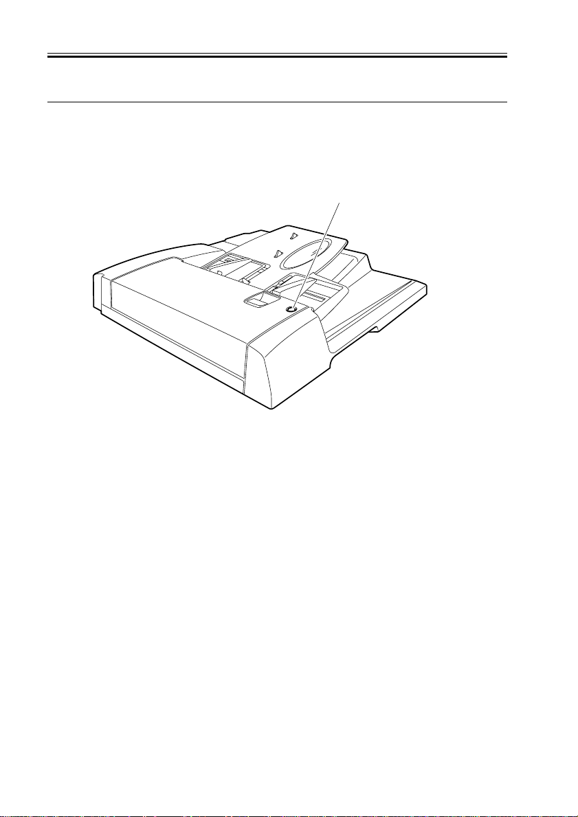
4.1 Document Set LED
The Document Set LED lights when a document is set in the document tray and flashes
when a document jams.
Document Set LED
F01-401-01
4.2 Alarm Indications and Corrective Action
If the Document LED flashes while feeding a document, the document may have jammed.
Take corrective action as follows:
1) Remove the entire document from the document tray.
2) Opening the feeder cover, remove any jammed document.
3) Set the document in the ADF again after aligning it, from the first sheet afterwards.
1-6
COPYRIGHT
©
2001 CANON INC. 2000 2000 2000 2000 CANON DADF-H1 REV.0 MAR. 2001
CHAPTER 1 GENERAL DESCRIPTION
4.3 Daily Customer Checks
Instruct the user to clean the following points at least once each month:
Cleaning point
Rollers
Platen roller
Blank plate (crimp plate)
Document table glass
Document table glass retainer
Cleaning method
After wiping with a cloth
saturated with water, then
wrung tight or moistened
with alcohol, wipe dry.
T01-403-01
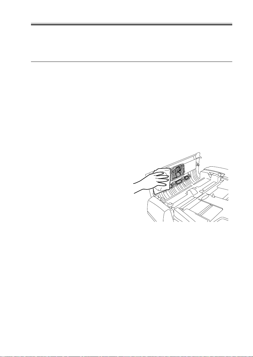
Perform cleaning in the following sequence:
1) Opening the feeder cover, clean the
rollers (5) under the feeder cover with a
cloth saturated with water, then wrung
tight while turning them and then wipe
dry with a soft, dry cloth.
Clean the areas surrounding the rollers
likewise.
Remarks
• Reader station part
• Reader station part
COPYRIGHT
©
F01-403-01
2001 CANON INC. 2000 2000 2000 2000 CANON DADF-H1 REV.0 MAR. 2001
1-7
CHAPTER 1 GENERAL DESCRIPTION
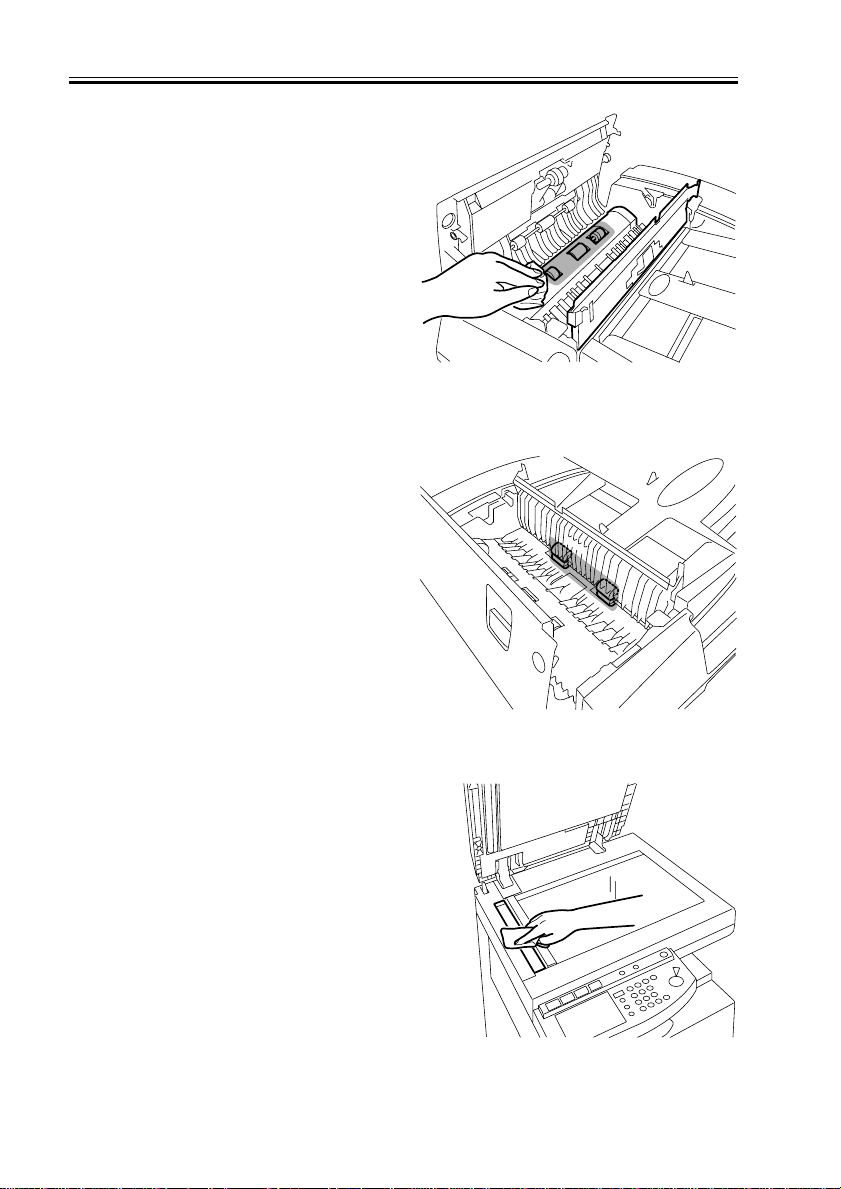
2) Opening the separation guide, clean
rollers (3) with a cloth saturated with
water, then wrung tight while turning
them and then wipe dry with a soft, dry
cloth.
Clean the areas surrounding the rollers
likewise.
3) Turning rollers (4) with knob, clean
them with a cloth saturated with water,
then wrung tight while turning them
and then wipe dry with a soft, dry cloth.
F01-403-02
4) With the separation guide and the feeder
cover closed, open the ADF. Clean the
document table glass with a cloth saturated with water, then wrung tight while
turning them and then wipe dry with a
soft, dry cloth.
1-8
COPYRIGHT
©
2001 CANON INC. 2000 2000 2000 2000 CANON DADF-H1 REV.0 MAR. 2001
F01-403-03
F01-403-04

5) Clean the platen roller with a cloth saturated with water, then wrung tight while
turning them and then wipe dry with a
soft, dry cloth.
Clean the sheets surrounding the rollers
likewise.
When the cleaning is completed, close
the ADF .
CHAPTER 1 GENERAL DESCRIPTION
F01-403-05
COPYRIGHT
©
2001 CANON INC. 2000 2000 2000 2000 CANON DADF-H1 REV.0 MAR. 2001
1-9

CHAPTER 1 GENERAL DESCRIPTION
1-10
COPYRIGHT
©
2001 CANON INC. 2000 2000 2000 2000 CANON DADF-H1 REV.0 MAR. 2001

CHAPTER 2
OUTLINE OF OPERATION
COPYRIGHT
©
2001 CANON INC. 2001 2001 2001 2001 CANON DADF-H1 REV.0 MAR. 2001
CHAPTER 2 OUTLINE OF OPERATION
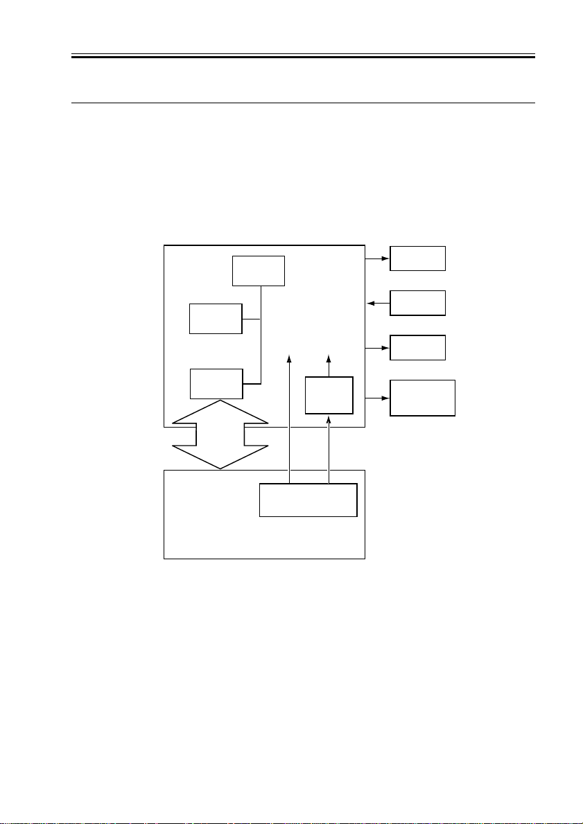
1 Basic Configuration
1.1 Electrical Circuit Schematics
This ADF is electrically controlled by the ADF controller PCB. A CPU (IC1) mounted
on the ADF controller PCB decodes signals input signals from sensors and other sources
and signals from the host and generates signals at predetermined timings for driving DC
loads, such as motors and solenoids.
ADF Controller PCB
EEPROM
(IC5)
IPC
(IC2)
IPC
Communication
2.1
Host Machine
CPU
(IC1)
+24V
F02-101-01
+5V
DC5V
power
(IC4)
J2-2
Power
Supply PCB
Motor
Sensor
Solenoid
Document
Set LED
J1-6
COPYRIGHT
©
2001 CANON INC. 2000 2000 2000 2000 CANON DADF-H1 REV.0 MAR. 2001
2-1

CHAPTER 2 OUTLINE OF OPERATION
1.2 ADF Controller PCB Input
ADF controller PCB input (1/1)
ADF
open/close
sensor
AR4/LTRR
identification
sensor
Tray
sensor 1
Tray
sensor 2
End-ofdocument
sensor
Document
width
detection
variable
resistor
Registration
roller paper
sensor
Read
sensor
Delivery
reversal
sensor
Cover
open/close
sensor
Document
set sensor
PI1
PI2
PI3
PI4
PI5
VR1
PI6
PI7
PI8
PI9
PI10
J301
-3
-1
-2
J305
-3
-2
-1
J306
-3
-1
-2
J307
-3
-1
-2
J308
-3
-2
-1
J302
-3
-1
-2
J303
-3
-1
-2
J304
-3
-1
-2
J309
-3
-1
-2
J310
-3
-1
-2
J102
J102
J102
J102
-10
-12
-11
J102
-13
-14
-15
+5V
ADF controller PCB
J3
-1
-3
-2
+5V
+5V
+5V
+5V
+5V
-1
-2
-3
-4
-5
-6
-7
-8
-9
?????
J13
-1
-2
-3
-4
-5
-6
-7
-8
-9
-1
-2
-3
-4
-6
-5
-7
-9
-8
J101
-1
-2
-3
-4
-5
-6
-7
-10
-12
-11
J5
-1
-2
-3
J6
-1
-2
-3
-4
J3
-4
-6
-5
J3
-7
-9
-8
J3
J4
-4
-6
-5
J4
-1
-3
-2
Set to 1 when the
ADFOP
+5V
Set to 1 when the paper loaded is AR4
A4R/LTR
Set to 0 when the paper loaded is LTRR
Set to 1 when paper is present
LENG1S
Set to 1 when paper is present
LENG2S
ENDS
Set to 1 when paper is present
VR
Detects the document width
(analog information)
For more details. see Section 2-19.
+5V
Set to 0 when paper is present
REGS
+5V
Set to 1 when paper is present
READS
+5V
Set to 1 when paper is present
EJTS
+5V
Set to 1 when the cover opens
COVERS
+5V
Set to 1 when paper is present
EMPS
ADF
opens
2-2
COPYRIGHT
©
F02-102-01
2001 CANON INC. 2000 2000 2000 2000 CANON DADF-H1 REV.0 MAR. 2001
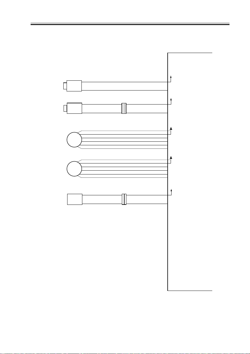
1.3 ADF Controller PCB Output
ADF controller PCB output (1/1)
Locking
solenoid
Stamp
solenoid
Pickup
motor
Feed
motor
Document
Set LED
SL1
SL2
M2
M1
LED
-2
-1
-2
J14
J201
-1-2-1
CHAPTER 2 OUTLINE OF OPERATION
ADF controller PCB
+24V
J10
-1
-2
A_SL SL1 turns on when 0
+24V
J11
-1
-2
STAMP_SL
SL2 turns on when 0
J8
+24V
-1
-2
-3
M2A
-4
-5
-6
J7
-1
-2
-3
-4
-5
-6
-1
-2
J11
-3
-4
For more details,
M2A*
see 2-30
M2B
M2B*
+24V
M1A
For more details,
M1A*
see 2-35
M1B
M1B*
+24V
LED
LED turns on when 0
COPYRIGHT
©
F02-103-01
2001 CANON INC. 2000 2000 2000 2000 CANON DADF-H1 REV.0 MAR. 2001
2-3

CHAPTER 2 OUTLINE OF OPERATION
2.Basic Operations
2.1 Overview
This machine is a flow-scanning document feeder that uses two motors to drive document
pickup and feeding.
Name (Symbol)
Pickup motor (M2)
Feed motor (M1)
Function
Separates and feeds documents.
Feeds documents.
T02-201-01
2-4
COPYRIGHT
©
2001 CANON INC. 2000 2000 2000 2000 CANON DADF-H1 REV.0 MAR. 2001
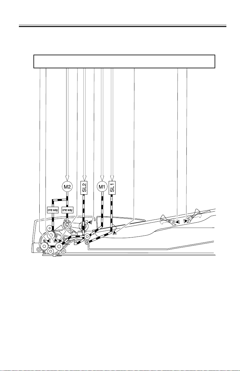
CHAPTER 2 OUTLINE OF OPERATION
A drive block diagram of this ADF is shown below.
ADF controller PCB
Pickup motor drive signal J8
Document detection signal (REGS) J3-6
Document detection signal (READS) J3-9
PI6
PI7
Document detection signal (EJTS) J3-12
PI8
Feed motor drive signal J7
Document set signal (EMPS) J4-3
Locking solenoid drive signal (A-SL) J3-9
Stamp solenoid drive signal (STAMP_SL) J11-2
PI10
F02-201-01
End-of-document detection signal (ENDS) J6-3
PI5
Paper size identification signal 1 (LENG2S) J6-1
Paper size identification signal 2 (LENG2S) J6-2
PI3
PI4
COPYRIGHT
©
2001 CANON INC. 2000 2000 2000 2000 CANON DADF-H1 REV.0 MAR. 2001
2-5

CHAPTER 2 OUTLINE OF OPERATION
2.2 Operations
2.2.1 Overview
This ADF supports four modes of operation as mentioned below. It chooses from among
these operation modes as directed from the host and executes the specified print operation.
The table below lists the names of the operation modes supported by this ADF, along with
summary descriptions of their operations and the associated print modes.
Operation mode name
[1] Forwarding pickup/delivery
[2] Forwarding pickup/reversal delivery
[3] Idle feed/reversal
pickup/reversal delivery
[4] Idle feed/reversal pickup
/delivery
Operation summary
Picks up a document, then delivers it when its scan is completed.
Picks up a document, then delivers it, reversed, when its
scan is completed.
Idle-feeds a document first to
establish its document size,
then to scan it on its surface,
and picks it again for scanning,
followed by reversal and delivery.
Idle-feeds a document to establish its document size, then reverses it for scanning, followed
by delivery.
T02-202-01
The small and large document sizes are as follows:
Associated print modes
Single-sided document
-> Single-sided print
Single-sided document
-> Double-sided print
Double-sided document
-> Double-sided print
Double-sided document
-> Single-sided print
Double-sided documents of different
sizes adhering to different systems
-> Double-sided print
Double-sided documents of different
sizes adhering to different systems
-> Single-sided print
Single-sided documents of different
sizes adhering to different systems
-> Single-sided print
Single-sided documents of different
sizes adhering to different systems
-> Double-sided print
Long document -> Single-sided
print
Small sizes: B6, A5R, A5, A4, B5, L TR, STMT
Large sizes: A4R, B5R, A3,B4,LTRR, LGL, 279.4 X 431.8mm (11" X 17")
T02-202-02
2-6
COPYRIGHT
©
2001 CANON INC. 2000 2000 2000 2000 CANON DADF-H1 REV.0 MAR. 2001
CHAPTER 2 OUTLINE OF OPERATION
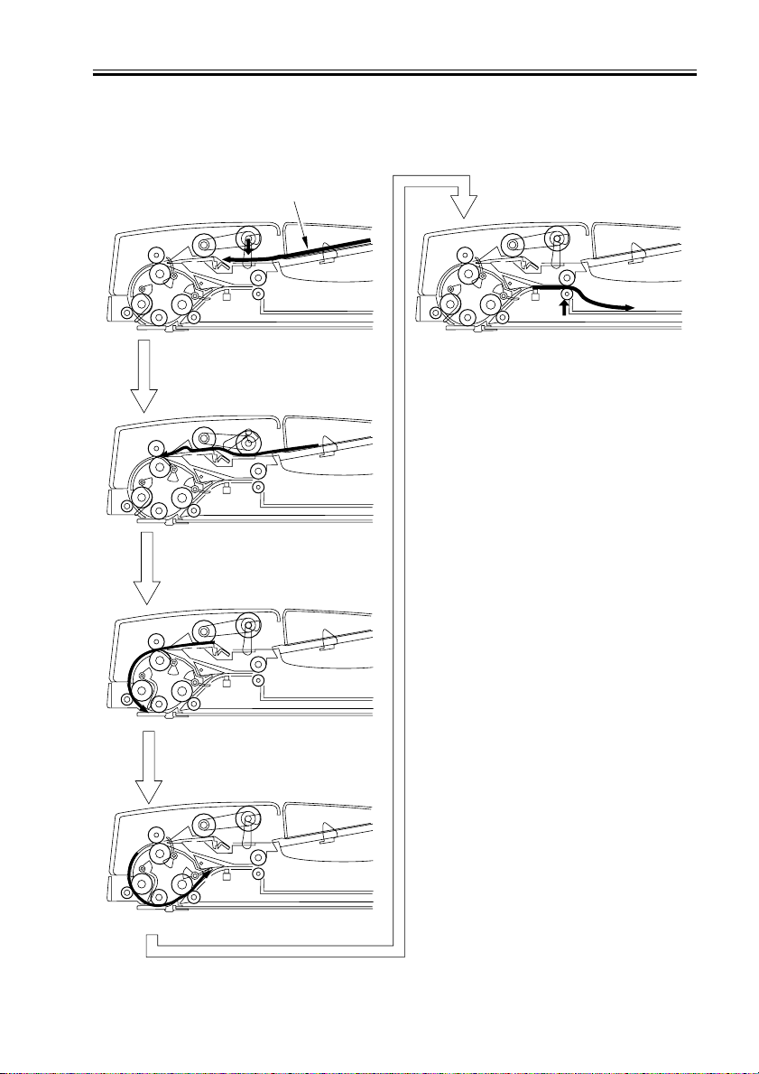
2.2.2 Forwarding pickup/deliv ery
(Single-sided document -> Single-sided print)
The flow of document handling is schematically shown below.
Document
Pickup
Looping
Scanning standby
Delivery
COPYRIGHT
©
Scanning
F02-202-01
2001 CANON INC. 2000 2000 2000 2000 CANON DADF-H1 REV.0 MAR. 2001
2-7
CHAPTER 2 OUTLINE OF OPERATION
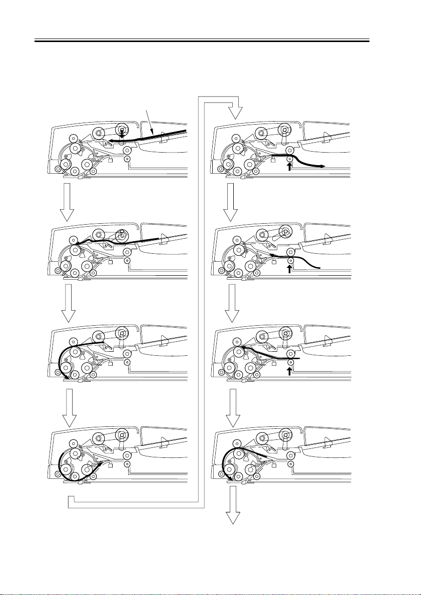
2.2.3 Forwarding pickup/re v ersal deliv ery
(Double-sided document -> Double-sided print)
The flow of document handling is schematically shown below.
Document
Pickup
Looping
Scanning standby
Feed
Reversal
Looping
2-8
Scanning
COPYRIGHT
©
Scanning standby
To next page
F02-202-02a
2001 CANON INC. 2000 2000 2000 2000 CANON DADF-H1 REV.0 MAR. 2001

CHAPTER 2 OUTLINE OF OPERATION
Back scanning
Feed
Reversal
Feed
Idle feed
Delivery
COPYRIGHT
©
Feed
F02-202-02b
2001 CANON INC. 2000 2000 2000 2000 CANON DADF-H1 REV.0 MAR. 2001
2-9
 Loading...