

Canon LV-5200U, D78-5383, D78-5382, LV-5200E Service Manual
SERVICE MANUAL
English Edition
LV-5200U/D78-5382
LV-5200E/D78-5383
By Portable Document Format
1
General
0
PREFACE
2
Repair
3
Adjustment
4
Troubleshooting
5
Parts Catalog
6
Electrical Diagrams
DY8-1785-381 500

CANON Power Projector
LV-5200U D78-5382
LV-5200E D78-5383
SERVICE
SMANUAL

Technical Documents
Application
This CD-ROM is issued by Canon Inc. for qualified persons to learn technical theory and product
repair. This CD-ROM covers all localities where the products are sold. For this reason, there
may be information in this CD-ROM that does not apply to the product sold in your locality.
The following paragraph does not apply to any countries where such provisions are
inconsistent with local law.
Trademarks
The product names and company names described in this CD-ROM are the registered
trademarks of the individual companies.
Copyright
Canon Inc. retains the copyright to all data contained on this CD-ROM.
Reproduction, publication (including on the World Wide Web) alteration, translation into another
language, or other use of the data in whole or part, contained on this CD-ROM without the
written consent of Canon Inc., is prohibited.
PDF Files
This CD-ROM contains PDF files created using Adobe® Acrobat 4.0J. PDF files can be viewed
using Adobe® Acrobat Reader 4.0 or later.
Copyright © 2003 by Canon Inc.
CANON INC.
30-2 Shimomaruko 3-Chome, Ohta-ku,
Tokyo 146-8501, Japan
First published March, 2003

PREFACE
1. Service Manual Composition
This manual contains information on servicing the product. It has the following sections.
Part 1 General Information
Provides the basic information needed to understand the product.
(Operating instructions are not included. Refer to the product's instruction book if
necessary.)
Part 2 Repair Information
Provides information for disassembly, reassembly, and adjustment of the product, about
the tools required, and their application.
Part 3 Adjustment
Provides information for disassembly, reassembly, and adjustment of the product to
assure precision of the products, about the tools required, and their application.
Part 4 Troubleshooting
Part 5 Parts Catalog
Part 6 Electrical Diagrams
2. Model Differences
In this series of products, there are models suffixed, "U", and "E". The only differences
between the models are cosmetic, mainly the designation and rating plates. Internally,
they are identical.
The accessories bundled with the product may differ from country to country.
I
Main Marketing Area North America Europe
MULTIMEDIA PROJECTOR MULTIMEDIA PROJECTOR
Model Name LV-5200U LV-5200E
LV-5200U LV-5200E

3. Tools & Test Equipment
The following tools and equipment are required to perform disassembly, reassembly and
adjustment.
1) Special Tools
None
2) General Purpose Tools (Commercially available, but can be purchased with the
following numbers.)
3) Test Equipment
4) Other Equipment
5) Chart/Software
II
Description Tool No. Specification Remarks
Ball Driver CY9-5002-000 2.0mm Optical Parts Removal
& Adjustment
Hex Key Set CY9-5007-000 2.0mm Optical Parts Removal
& Adjustment
Driver, adjustment CY9-5003-000 1.8mm Electrical Adjustments
Driver, Slot CY9-5004-000 4.0mm Optical Parts
Adjustment
Driver, Cross-point CY9-5005-000 No. 2 Assembly &
Disassembly
Description Tool No. Specification Remarks
Digital Multi-meter Commercially available DC1mmV~500V Electrical Adjustment
Video Signal Generator Commercially available Color Bars and Electrical Adjustment
Gray Scale
Computer Signal Commercially available Gray Scale Electrical Adjustment
Generator (or personal computer)
Oscilloscope Commercially available 100MHz response or Waveform checks
over
Description Tool No. Specification Remarks
Screen Commercially available Over 40" All Adjustment
Personal Computer Commercially available Windows 95 OS All Adjustment
(with a floppy disk)
Description Tool No. Specification Remarks
Monitor Tester Supplied with manual Bitmap Data Electrical Adjustment
Gray Scale Chart Supplied with manual (XGA and SVGA) Electrical Adjustment
Color Shading Supplied with manual Ver. 3.02 White Uniformity
Correction Tool Adjustment

CONTENTS
Page
Part 1: General Information
1. FEATURES ...................................................................................................... 1-1
1.1 Development Objectives .......................................................................... 1-1
1.2 Product Overview .................................................................................... 1-1
1.3 Main Features .......................................................................................... 1-2
2. SPECIFICATIONS ........................................................................................... 1-3
2.1 Type ......................................................................................................... 1-3
2.2 LCD Panel ............................................................................................... 1-3
2.3 Optics ....................................................................................................... 1-3
2.4 Images ..................................................................................................... 1-3
2.5 Image Signals .......................................................................................... 1-3
2.6 Mechanisms ............................................................................................. 1-4
2.7 Connectors .............................................................................................. 1-4
2.8 Ratings ..................................................................................................... 1-4
3. FUNCTIONS .................................................................................................... 1-5
3.1 Optics ....................................................................................................... 1-5
3.2 Image ....................................................................................................... 1-5
3.3 Image Signal ............................................................................................ 1-7
3.4 Mechanisms and Systems ....................................................................... 1-7
4. ACCESSORIES ............................................................................................... 1-9
4.1 Principal Accessories ............................................................................... 1-9
4.2 Replacement Parts .................................................................................. 1-9
4.3 Optional Parts .......................................................................................... 1-10
5. PRECAUTIONS FOR USE .............................................................................. 1-11
6. OUTLINE DRAWINGS ..................................................................................... 1-12
7. CONNECTORS ............................................................................................... 1-13
8. DESCRIPTION ................................................................................................ 1-14
8.1 Optics ....................................................................................................... 1-14
8.2 Image ....................................................................................................... 1-14
8.3 Mechanism .............................................................................................. 1-15
Part 2: Repair Information
1. SAFETY INSTRUCTIONS ............................................................................... 2-1
2. CIRCUIT PROTECTIONS ............................................................................... 2-2
2.1 Fuse ......................................................................................................... 2-2
2.2 Thermal Switch ........................................................................................ 2-2
2.3 Interlock Switch ........................................................................................ 2-2
2.4 Warning Temperature and Power Failure Protection .............................. 2-3
2.5 Air Filter Care and Cleaning .................................................................... 2-3
3. SERVICE (MECHANICAL DISASSEMBLIES) ................................................ 2-4
3.1 Cabinet Top and Control Panel Removal ................................................ 2-4
3.2 Main Board Removal ............................................................................... 2-4
3.3 AV, DVI, Temp Board and Speaker Removal .......................................... 2-5
3.4 Front Panel and R/C Board Removal ...................................................... 2-5
III

3.5 Lamp Ballast Unit Removal ..................................................................... 2-6
3.6 Filter Board Removal ............................................................................... 2-6
3.7 Power Box Cover and Fans (FN901, FN906) Removal ........................... 2-7
3.8 Optical Unit Removal ............................................................................... 2-7
3.9 Power and P.F. Board Removal .............................................................. 2-8
3.10 Fan (FN905) Removal ........................................................................... 2-9
3.11 Fans (FN902, FN903, FN904) Removal ................................................ 2-9
4. OPTICAL PARTS DISASSEMBLIES ............................................................... 2-10
4.1 Projection Lens Removal ......................................................................... 2-10
4.2 Integrator Lens-In Disassembly ............................................................... 2-10
4.3 Condenser Lens Disassembly ................................................................. 2-11
4.4 Condenser Lens-Out Disassembly .......................................................... 2-11
4.5 Relay Lens-Out Disassembly .................................................................. 2-12
4.6 Polarized Glass-In Removal .................................................................... 2-12
4.7 Polarized Glass-Out/Pre-Polarized Glass Removal ................................. 2-13
4.8 Optical Unit Top Removal ........................................................................ 2-13
4.9 Locations and Directions ......................................................................... 2-14
5. LCD PANEL/PRISM ASS'Y REPLACEMENT ................................................. 2-15
5.1 LCD Panel/Prism Ass'y Removal ............................................................. 2-15
5.2 Note on LCD Panel/Prism Ass'y Mounting .............................................. 2-16
6. CLEANING ....................................................................................................... 2-17
7. LAMP REPLACEMENT ................................................................................... 2-18
Part 3: Adjustment
1. PRECAUTIONS FOR ADJUSTMENT ............................................................. 3-1
1.1 Adjustments after Parts Replacement ..................................................... 3-1
1.2 Service Adjustment Menu Operation ....................................................... 3-2
1.3 Service Adjustment Data Table ............................................................... 3-3
2. ELECTRICAL ADJUSTMENTS ....................................................................... 3-7
2.1 Output Voltage Adjustment ...................................................................... 3-7
2.2 Fan Voltage Adjustment .......................................................................... 3-8
2.3 Signal Center Adjustment ........................................................................ 3-8
2.4 PSIG Adjustment ..................................................................................... 3-8
2.5 Gain Adjustment [PC] .............................................................................. 3-9
2.6 Gain Adjustment [Video] .......................................................................... 3-9
2.7 Gain Adjustment [Component] ................................................................. 3-10
2.8 Gamma Gain Adjustment [PC] ................................................................ 3-10
2.9 Gamma Gain Adjustment [AV] ................................................................. 3-11
2.10 Common Center Adjustment ................................................................. 3-11
2.11 Signal Offset Adjustment [PC] ............................................................... 3-12
2.12 Signal Offset Adjustment [AV] ............................................................... 3-12
2.13 White Balance Adjustment ..................................................................... 3-12
2.14 Note On White Uniformity Adjustment ................................................... 3-13
3. OPTICAL ADJUSTMENTS .............................................................................. 3-14
3.1 Contrast Adjustment ................................................................................ 3-14
3.2 Condenser Lens Adjustment ................................................................... 3-15
3.3 Condenser Lens-Out Adjustment ............................................................ 3-16
3.4 Relay Lens-Out Adjustment ..................................................................... 3-17
IV

3.5 Optical Adjustment Setting ...................................................................... 3-18
4. TEST POINTS AND LOCATIONS ................................................................... 3-19
Part 4: Troubleshooting
1. TROUBLESHOOTING ..................................................................................... 4-1
1.1 No Power ................................................................................................. 4-1
1.2 No Picture ................................................................................................ 4-3
1.3 No Sound ................................................................................................. 4-5
1.4 Lens Motor Problems ............................................................................... 4-6
2. CHASSIS BLOCK DIAGRAMS ........................................................................ 4-7
2.1 Chassis Over View .................................................................................. 4-7
2.2 Inputs & Video Signal Processing Stage ................................................. 4-8
2.3 LCD Panel Driving Stage ......................................................................... 4-9
2.4 Audio Signal Processing Circuit ............................................................... 4-10
2.5 Motor Driving Circuit ................................................................................ 4-11
2.6 System Controls ...................................................................................... 4-12
2.7 Power Supply & Protection Circuit ........................................................... 4-13
2.8 Fan Control Circuit ................................................................................... 4-14
3. CONTROL PORT FUNCTIONS ...................................................................... 4-15
3.1 System Control & I/O Port Table ............................................................. 4-15
4. WAVEFORMS ................................................................................................. 4-17
5. IC BLOCK DIAGRAMS .................................................................................... 4-18
Part 5: Parts Catalog
Part 6: Electrical Diagrams
1. PARTS DESCRIPTION AND READING IN SCHEMATIC DIAGRAM..............6-1
2. DIODE, TRANSISTOR AND IC PINS...............................................................6-3
Schematic Diagrams .........................................................................................A3
Printed Wiring Board Diagrams.........................................................................A10
V

Part 1
General
Information
1. FEATURES
1.1 Development Objectives
At present, SVGAs between 1500 and 2000 ANSI comprise a fixed market scale
worldwide. However, as of December 2002, Canon's projector lineup does not contain
products in this class. To boost overall competitiveness, the need to strengthen the
lineup is urgent.
Thus, Canon aims to enrich the product lineup and expand its market share by
committing to types of products that are price-competitive in this product class.
To expand projector sales in 2003, a product has been commercialized as a new
product (featuring SVGA, 1700 ANSI and weight of 4.3kg). This product uses the casing
and other elements of existing models. Canon thus aims to expand its projector
business sales volume in kind.
1.2 Product Overview
The exterior and projection lens of the LV-7355 and LV-7350 (hereinafter collectively
referred to as the LV-7350) were appropriated for this product, and Canon's first 0.8type SVGA liquid crystal panels were adopted to actualize a low-price model featuring
high brightness: 1700 ANSI lumens. With uses spanning a wide range from business to
personal, this Multimedia Projector will ensure satisfaction.
* The following LV-7350 functions have been eliminated:
Turbo Bright functions, horizontal keystone correction and accommodation of options
(LV-WI01 and LV-MC01)
Part 1: General Information
1-1
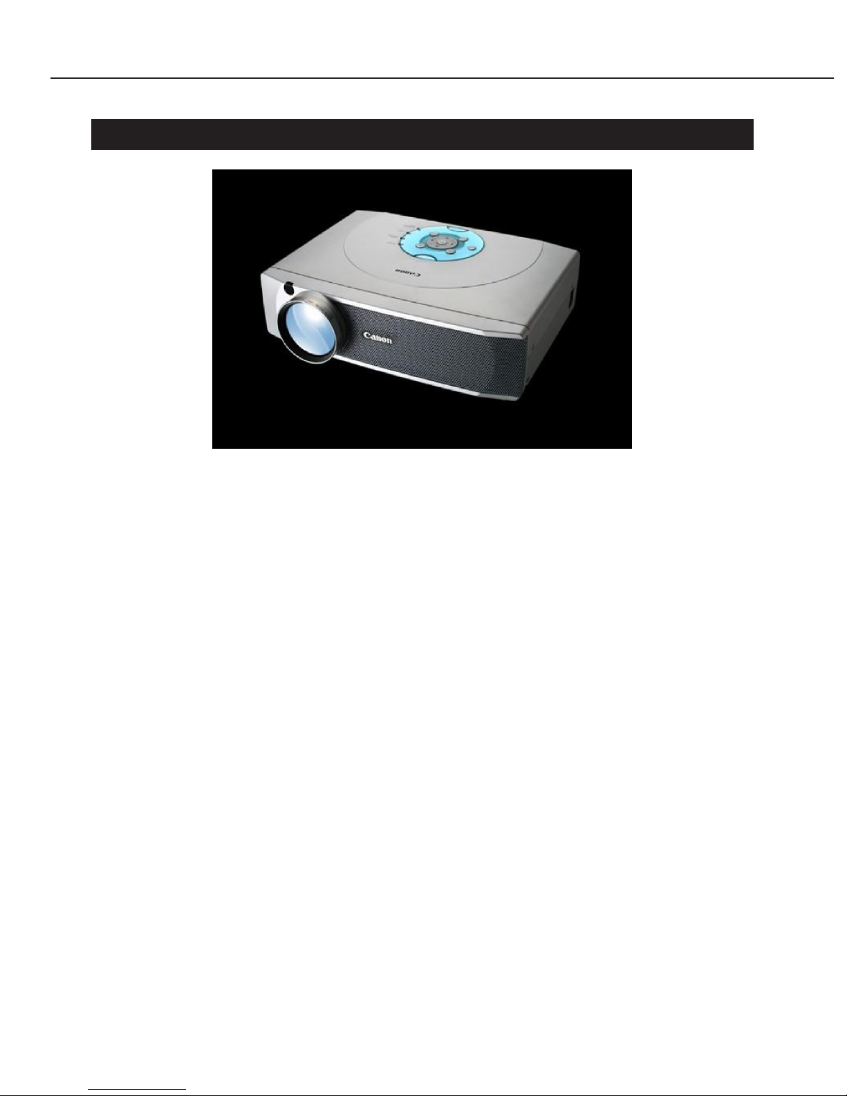
Fig. 1-1 LV-5200 External View

1.3 Main Features
● SVGA features 1700 ANSI lumens and a contrast ratio of 400 : 1
With the advantages of the LV-7350 fully utilized, 0.8-type panels were combined with
a highly efficient 180-watt UHP lamp to achieve 1700 ANSI lumens.
In addition, the new type of SVGA panel of 800 × 600 pixels achieves a 400 : 1
contrast ratio. Real SVGA and digital compression technology enable high-quality
XGA projection.
● Silent mode (34 dB)
This product's lamp can be switched from 180 watts (normal) to 150 watts (silent).
When operating on low electric power in silent mode, the fan speed is curbed and
noise silenced to 34 dB (A).
When projecting on smaller screens in small meeting rooms or the like, projection of
sufficient brightness can be obtained even with low electric power; thus, in addition to
operating on low electric power in silent mode, a quiet room environment can be
facilitated.
● 1.5××wide zoom lens
This product is equipped with an electromotive zoom lens of the industry's highest
magnification rate, 1.5×, which is the same as for the LV-7350.
For the 100-type screen, the projection distance ranges from 3.2 meters to 4.8 meters.
* In terms of screen size, values will not be the same as for the LV-7350, even at the
same projection distance. (See "Description.")
● Analog RGB Output (switching)
This product can be used with the analog RGB terminal switched to either input or
output.
Use as an output terminal is possible when the DVI-I terminal is used for RGB input.
● Conforms to SCART standards
With the optional cord, input signals from DVD players and other devices having a
SCART output terminal can be accommodated. Thus, this product adapts to an even
larger hardware environment.
● OSD accommodates 12 languages
Russian has been added to the conventional 11 languages: English, German, French,
Spanish, Italian, Portuguese, Dutch, Swedish, Chinese, Korean and Japanese.
Part 1: General Information
1-2

Part 1: General Information
1-3
2. SPECIFICATIONS
2.1 Type
1. Type: Projector
2. Product class: Ultra Portable class
3. Imaging element: Transmitting LCD panel
2.2 LCD Panel
1. Type: Polysilicon-TFT active matrix
2. Size and number: 16 mm × 12 mm (0.8", 4:3 aspect ratio ), 3 panels
3. Number of pixels: 48000 (800 × 600, SVGA)
2.3 Optics
1. System: Dichroic mirror separation and X-prism
combination system
2. Light source: 180 W UHP lamp
3. Projection lens configuration: 10 groups of 12 lenses
4. F number and focal length: F1.7 to 2.4, f = 25.7 to 37.9 mm
5. Zoom: 1.5 times, Motorized
6. Focus: Motorized
7. Lens shift: 26:1, fixed
2.4 Images
1. Brightness: 1700 ANSI lm (at normal mode) , 90% marginal
lumination ratio
2. Contrast ratio: 400:1 (all white to all black)
3. Projection distance coverage: 1.1 to 9.7 m
4. Screen size: 24" (0.49 m × 0.37 m) to 300" (6.10 m × 4.57 m)
5. Electronic zoom magnification: ×0.6 to ×4
6. Keystone correction range: ±20 degrees in up/down direction
2.5 Image Signals
1. Computer input: XGA (compression)/SVGA/VGA
2. Color systems *composite/S-Video: NTSC/PAL/SECAM/NTSC4.43/PAL-M/PAL-N
3. Scanning systems *component: 480i/480p/575i/575p/720p/1035i/1080i
4. Horizontal resolution: 500 TV lines *S-Video
5. Scanning frequency: H-sync: 15 to 80 kHz, V-sync: 50 to 100 Hz,
Dot clock: 100 MHz

2.6 Mechanisms
1. Adjustable feet, bottom front: Can be adjusted to raise the main unit a maximum
of 15.6º
2. Built-in speaker: 4 cm × 3 cm, 1 W, Monaural
2.7 Connectors (For further details, see "Connectors" in section 9.)
1. Digital RGB input DVI-I 29-pin
2. Analog RGB input (2 systems): Mini D-sub15 pin & DVI-I29 pin (also used for
digital)
3. Composite video input: RCA × 1
* VIDEO (also used for Y) terminal is only used
4. Component video input: RCA × 3
* 3 terminals (Y, Cb/Pb, Cr/Pr) are used
5. S-Video input: Mini DIN 4-pin
6. Audio input: Video: RCA × 2, Computer: Stereo mini-jack
7. Analog RGB output: Mini D-sub15-pin (also used for input, can be
switched)
8. Audio output: RCA × 2
9. Mouse control (2 systems): Mini DIN 8-pin, USB type B
2.8 Ratings
1. Dimensions (Not total length): W: 331.5 mm, D: 244.1 mm, H: 89.5 mm
(See Outline Drawings)
2. Weight: 4.3 kg
3. Rated supply voltage: J: 100 V / U: 100 to 120 V / 200 to 240 V,
50/60 Hz
4. Power consumption: 260 W
5. Noise: 36 (normal)/34 (silent) dB (A)
6. Ambient temperature range: 5 to 35 ºC
7. Storage temperature range: –10 to 60 ºC
Part 1: General Information
1-4
3. FUNCTIONS
3.1 Optics
● Electromotive zoom and focus (same projection lens as the LV-7350)
The wide, telephoto zoom rate is 1.5×. Electromotive zooming is done within this
range, and projection size is variable. In addition, focus is similarly electromotive,
making appropriate position alignment possible.
3.2 Image
● Projection distance and projection screen size
The appropriate projection distance is between 1.1 and 9.7 meters; thus, screens
range from 24 to 300 inches.
The following table presents the relationship between screen size and projection
distance.
* H1 and H2 are the lengths that result from dividing the screen's height - top and
bottom - with the lens's optical access as the boundary.
For this product, 26:1 is the ratio that results from the lens shift setting.
● Keystone correction
This function corrects trapezoidal distortion of the projection screen resulting from
how the projector is positioned. It functions within a range of ±20º in the up-down
direction. (It does not function in the left-right direction.)
● Image mode selection (by remote control)
Image mode can be selected depending on the type of input, as follows.
* [IMAGE] button: Switches the image mode, [INPUT] button: Switches the input
• Standard
This setting is the average of images overall, both computer and video.
• High contrast (for computer input)
This function brightly reproduces domains of medium brightness, thus showing the
entirety brightly.
Part 1: General Information
1-5
Screen
Size[cm]
Projection Zoom max
distance [m] Zoom min
H1 [cm]
H2 [cm]
24 type
49 × 37
(0.72)
1.10
35
1
36 type
73 × 55
1.11
1.67
53
2
100 type
203 × 152
3.18
4.76
147
6
150 type
305 × 229
4.80
7.16
220
8
200 type
406 × 305
6.42
9.57
294
11
300 type
610 × 457
9.66
(14.39)
440
17
Computer input
Video input
Standard
Standard
High-contrast
Cinema
Custom
Custom

• Cinema (for video input)
This function raises domains of low brightness, thus improving their reproducibility.
It has the effect of improving the reproducibility of dark scenes, which often occur in
movies and the like.
• Custom mode
Makes it possible to adjust any of the aforementioned with an additional ±8 stages,
enabling the user to fine-tune reproducibility according to preference.
● Electronic zoom
The desired area on the screen can be projected anywhere from 0.6 times to 4 times
(enlarged or reduced).
● Auto-Grayscale
This feature is effective in clearly displaying dark or low-contrast scenes that appear
blurry, such as nighttime scenes.
Turning this feature on automatically controls the image signal output so that the
black levels and white levels of the output image are maximized.
● Auto-Flesh tone
Processes the image so that the skin tones of people shown in an image more
faithfully reflect those of actual people.
Turning this feature on modulates human skin tones so that they approach
predetermined settings.
Since this modulates tones, the background and other areas will be shown in colors
that differ from actual colors.
● Freezing the screen (by remote control)
Pressing the [FREEZE] button will fixate the screen currently displayed.
Use this function when you do not want to show the content of output devices on the
screen, such as when performing tasks at a computer.
● Showing no images (by remote control)
Use the [NO SHOW] button to display a blank screen instead of images.
● Presentation timer (by remote control)
Pressing the [P-TIMER] button will start a count of the time that elapses, which will be
displayed in the corner of the screen. Each time this button is pressed, the function
will change as follows: start (display), stop, and reset (clear the display).
● Image reversal
Settings for left-right reversed projection when projecting from the rear and left-right
or up-down reversed projection when projecting from the ceiling can all be made.
● Blue-back display
When a video input has been selected, this setting prevents a noise screen from
appearing even when there is no image signal input.
Part 1: General Information
1-6

3.3 Image Signal
● Computer input
• System mode
Accommodates XGA, SVGA and VGA signals. Input can be analog or digital (DVI).
For real SVGA projection, 0.8-type LCD panels with 800 × 600 pixels are used.
Digital compression technology makes high-quality XGA projection possible.
• Multi-scan system
This system distinguishes the horizontal and vertical frequencies of the image
signals from a computer that has been connected and automatically selects the
appropriate system mode.
• Automatic PC adjustment function
Can be set to automatically adjust three items: the screen's total number of dots in
the horizontal direction, tracking and screen position.
● Composite input or S-Video input
• Color systems
The following color systems are accommodated: NTSC, PAL, SECAM, NTSC4.43,
PAL-M and PAL-N.
Selecting AUTO enables the projector to automatically accommodate the appropriate
color system, excluding PAL-M and PAL-N.
● Component input
• Scanning systems
The following systems are accommodated: 1080i, 1035i, 720p, 575p, 480p, 575i and
480i. (Selection can be made automatically or manually.)
Accommodates color-differentiated signals (Y, Pb/Cb, Pr/Cr). Images can be
obtained with no subdued colors.
3.4 Mechanisms and Systems
● Adjustable feet
Adjustable feet have been provided on the front bottom of the main unit on the side of
the projection lens. These feet can be adjusted to set the projector at an incline,
enabling projection at an angle. A maximum angle of elevation of 15.6º can be
established between the projector's optical axis and the table on which the projector
rests.
With one touch, the lock on the adjustable feet can be released and the feet stored
inside the main unit.
* The aforementioned keystone correction function can be used to eliminate
trapezoidal distortion resulting from the projector being at an incline.
Part 1: General Information
1-7

● Sound muting (remote control function)
Use the [MUTE] button on the remote control to turn sound off and on.
* The built-in 1-watt output speaker reproduces sound from PCs or videos in
monaural.
● Power management
This function can be set so that the lamp automatically turns off if no image signals
have been input for a set time (5 min.) and the projector has also not been operated.
This power-management status will automatically be released when image signals are
again input or the projector has again been operated. (The 90-second cooling
operation that occurs directly after shutting off will not be released.)
● Power ON - Start
The projector can be set so that it starts up as soon as the power cord has been
connected.
● Graphical user interface
Pressing the MENU button will display a menu bar on the screen.
The display can be shown in one of eleven languages: English, German, French,
Spanish, Italian, Portuguese, Dutch, Swedish, Chinese, Korean or Japanese.
This multilingual feature enables the projector to be used around the world.
● Voltage specifications to accommodate usage worldwide
The product is equipped with a power supply mechanism that accommodates sources
of electricity from 90 to 264 volts.
Part 1: General Information
1-8

4. ACCESSORIES
4.1 Principal Accessories
● Remote control unit
This wireless tool can be used for a variety of image-control purposes.
Equipped with laser-pointer function, it can also be used to direct a red laser beam
anywhere on the screen.
Remote control's specifications
• Power: DC 3.0 V; uses 2 dry-cell type-3 alkaline batteries
(which are included)
• Maximum distance operable: About 5 m (from the front of the receiver)
• Dimensions: 5.5 cm (W) × 19.2 cm (D) × 3.4 cm (H)
• Weight: 165 g
• Maximum laser output: 1 mW (class-2 laser product; IEC60825-1, Am.1, 1997)
• Laser wavelength: 650 ±20 nm
● VGA Cable (Dsub15-Dsub15)
Use when inputting analog RGB image signal from a PC or the like.
● DVI/VGA adapter
Use when inputting analog RGB image signal to the digital RGB input terminal from a
PC or the like.
● Mouse Control cable
Use for PS/2 port.
4.2 Replacement Parts
● Canon's replacement lamp: LV-LP16
This lamp has a display that lights when the lamp needs to be replaced.
We recommend replacing the lamp every 1,500 hours at normal mode.
We recommend replacing the lamp every 2,000 hours at silent mode.
* 50% of the lamps will last for this time, with 50% of their illumination maintained.
Part 1: General Information
1-9

4.3 Optional Parts
● SCART-VGA cable: LV-CA31
This connecting cable is new for the product.
Use when connecting to the video apparatus with SCART output terminals.
● Canon's metal fixture for suspending projector from ceiling: LV-CL05
This hanger part is used for suspending the projector from the ceiling.
* Consult a professional to install the projector in this way.
● Others
LV-CA29 for DVI, LV-CA26 for serial, LV-CA27 for PDA
Part 1: General Information
1-10

5. PRECAUTIONS FOR USE
● After the lamp has turned off, do not unplug the projector until its fan has stopped.
Insufficient cooling is a cause of trouble.
* To avoid the danger of being burned, make sure the lamp has cooled for at least 45
min. before replacing it.
● Do not peer into the projection lens while it is emitting light.
The strong light of the high-bright projection could result in damage to one's vision.
● Although the laser pointer built into the remote control meets class-2 safety standards,
do not peer directly into the light-emission source or point it at anyone.
● When the indication to replace the lamp appears, install a new lamp promptly.
The lamp used in the light source is a high-pressure mercury lamp. One feature of
mercury lamps is that they can shatter from deterioration resulting over the course of
their use.
If a lamp shatters, we recommend that you contact your place of purchase and
arrange for a replacement and inspection.
Part 1: General Information
1-11
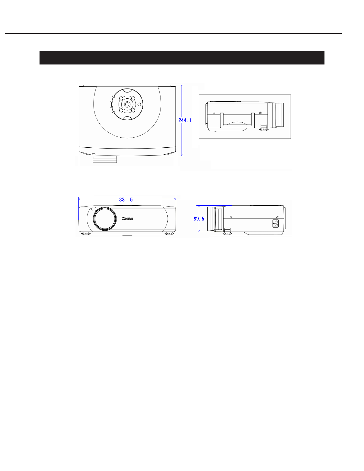
6. OUTLINE DRAWINGS
Part 1: General Information
1-12
Fig. 1-2
Dimensions: (Not total length) W: 331.5 mm, D: 244.1 mm, H:89.5 mm
Weight: 4.3 kg
* Dimensions are the same as for the LV-7350.
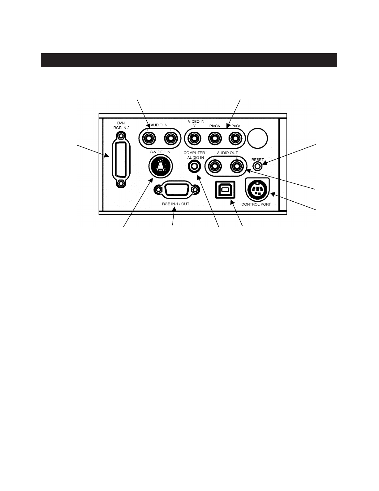
7. CONNECTORS
On the back of the main body are input systems, output systems and control ports.
● Computer input
A: Mini Dsub15 pin (Image) Analog RGB input
B: DVI-I29 pin (Image) Digital & analog RGB input
C: Mini pin jack (Audio) Stereo input
● Video input
D: RCA × 3 (Image) Component input with Y, Cb/Pb, Cr/Pr
RCA × 1 (Image) Composite input with VIDEO (also used for Y)
E: Mini DIN4 pin (Image) S image input with S-VIDEO
F: RCA × 2 (Audio) Stereo input
Note: The built-in speaker outputs in monaural.
● Output
A: Mini Dsub15 pin (Image) Analog RGB output
G: RCA × 2 (Audio) Stereo output
● Mouse control (links PC or the like with projector via cable)
H: USB type B USB port
I: Mini DIN8 pin Control port
● Other
J: Reset button Restarts the projector
Part 1: General Information
1-13
F D
B
E A C H
J
G
I
Fig. 1-3
8. DESCRIPTION
8.1 Optics
Equipped with the wide zoom lens appropriated from the LV-7350 and new 0.79-size
LCD panels (Nominal value is 0.8), this low-price model provides high brightness and
high contrast.
In terms of brightness, switching the lamp's current enables two modes to be used:
high or low brightness. (refer to the item of mechanism)
● 1.5××wide zoom lens
This 6-group zoom type is based on the 10-group, 12-lens configuration of the LV-
7350.
A compact, wide-angle lens, it features the industry's highest magnification.
Pb-free materials have been adopted for the lens.
● LCD panel
For this product, Canon has adopted 0.79-type LCD panels (2.0 cm diagonal) for the
first time.
8.2 Image
● Projection screen size
Although the same projection lens is used as for the LV-7350, the LCD panels are
smaller. Screen size is simply in proportion to panel size. Values for screen size at
the same projection distance are the values for the LV-7350, multiplied by 0.79/0.9.
Screen size values (inches) calculated for projection distance
* Includes ranges outside the specifications
● Connection of the cable for SCART (*1)
The image signal from the SCART terminal is connected to the analog RGB input
(Dsub15) by the cable LV-CA31 (option).
In addition, this cable (LV-CA31) does not supported about audio signal.
*1 SCART is the standard of input and output of the video apparatus that is currently
used widely in Europe. In this standard, RGB image signal and audio signal are
transmitted using the terminal of 21 pins.
Part 1: General Information
1-14
Distance
LV-7350
LV-5200
2 m
48.8 to 72.9
42.8 to 63.6
3 m
72.6 to 108
63.5 to 94.5
4 m
96.4 to 144
84.3 to 125
5 m
120 to 179
105 to 156
6 m
144 to 215
126 to 187
7 m
168 to 250
147 to 218
8 m
191 to 285
167 to 249
1 m
25.1 to 37.5
22.0 to 32.7

8.3 Mechanism
● Cooling mechanism and Silent mode
In this model, the air flow mechanism is fundamentally the same as that of LV-7350.
However, the lamp has been changed into 180 watts from 200 watts, as the result, the
amount of heat has been decreased compared with LV-7350. Consequently, the fan
speed could be lowered.
Furthermore noise level has been down to 36 dB(A) from 37 dB(A).
And when the silent mode is selected, the lamp power is controlled to 150 watts, and
the fan speed has been down, as the result this model becomes the more of energy
saving and more silent as 34 dB(A).
Also this model has the system of the automatic fan speed control as same as the
previous models.
Part 1: General Information
1-15
Normal
Silent
1700 ANSI lm
82% of above value
36 dB(A)
34 dB(A)

Part 2
Repair
Information
1. SAFETY INSTRUCTIONS
The following precautions must be observed during servicing and inspection.
Observe all safety precautions.
Comply with all caution and safety-related notes provided on the cabinet back, cabinet
bottom, inside the cabinet, on the chassis or components, as well as the precautions
shown in the instruction manual during servicing.
Avoid electric shock.
Since an AC voltage is applied to the chassis for the set, touching the chassis during
power-on may cause electric shock. When service is performed during power on, use an
insulation transformer, wear protective gloves, and remove the plug during parts
replacement.
Use specified parts.
The parts of the set have safety properties, such as inflammability and voltage
withstand. Therefore, use replacement parts with the same characteristics as the
original ones. The critical components for safety are indicated by mark in the
schematic diagram and parts list must be replaced by the recommended parts.
Reinstall parts and wires in their original positions.
Insulating materials, such as tubes and tape, are used and some components are
installed over a PC board for safety. Reinstall internal wires with clamps so that they do
not touch any heat-generating or high-voltage parts.
Safety check after service
Verify that service locations are not deteriorated and all removed screws, parts and
wires are installed in their original positions. In addition, perform the following test to
ensure safety.
Insulation resistance test method
Remove the plug from the electric outlet and press the power switch. Using a 500V
insulation resistance tester (or a multimeter if any insulation resistance tester is not
available), check that the insulation resistance between each terminal of the plug and
external exposed connector (external speaker connector, remote control connector, AV
input/output connector, etc.) is 1 Mohm or higher. If not, the set must be inspected
and repaired.
Precautions for servicing
Part 2: Repair Information
2-1
Components indicated by mark in the parts list and the schematic diagram designate components in
which safety can be of special significance. It is, therefore, particularly recommended that the
replacement of there parts be made by exactly the same parts. Using unspecified parts may worsen
failure or cause fire or electric shock.
Eye damage may result from directly viewing the light produced by the lamp used in this equipment.
Always turn off the lamp before opening the cover.
Never turn the power on without the lamp to avoid electric shock or damage of the devices since the
stabilizer generates high voltages (15kV - 25kV) at its starts.
Since the lamp is very high temperature during units operation replacement of the lamp should be done
at least 45 minutes after the power has been turned off, to allow the lamp cool-off.
2. CIRCUIT PROTECTIONS
This projector is equipped with the following circuit protections to operate in safety. If
the abnormality occurs inside the projector, it will automatically turn off by operating
one of the following protection circuits.
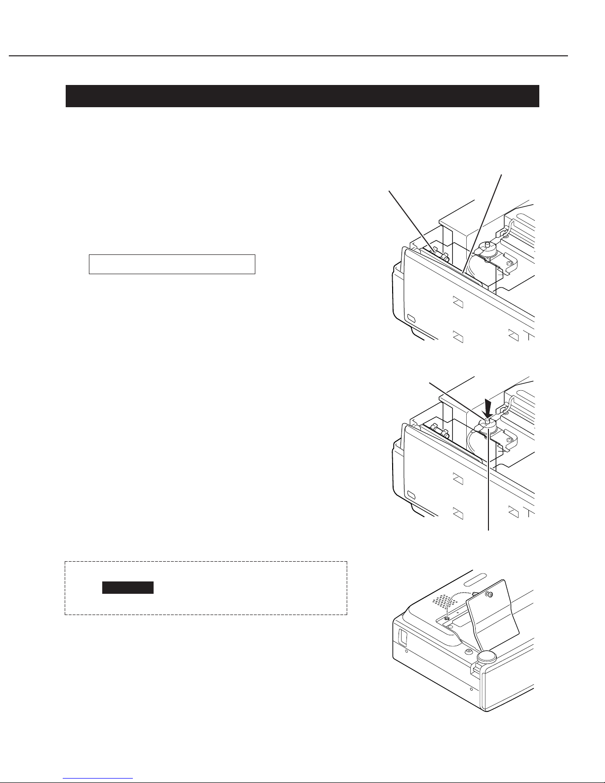
2.1 Fuse
The fuse is located inside of the projector. When
either the LAMP indicator or the READY indicator is
not illuminated, a fuse may be opened. Check the
fuse according to the following steps. The specified
fuse should be used as follows;
[How to replace the fuse]
1. Remove the cabinet top and main board according
to step 1 of "Service (Mechanical Disassembles)".
2. Remove the fuse from fuse holder.
To install the fuse, take reversed step in the above.
2.2 Thermal Switch
When the internal temperature of the projector
reaches near 100 ˚C, the thermal switch (SW902)
turns off the AC main power supply automatically.
(Check the resistance between the terminals of the
thermal switch by using a tester. If it is open, the
thermal switch may be in operative.)
Reset the thermal switch according to the following
procedure.
[How to reset the thermal switch]
1. Remove the cabinet top according to step 1 of
"Service (Mechanical Disassembles)".
2. Press the reset button on the thermal switch.
2.3 Interlock Switch
The interlock switch (SW904) cuts AC power when
the lamp cover is removed. If the lamp cover is
opened to replace the lamp, the projector does not
start. Reinstall the lamp cover.
Fuse Part No. CY2-8376-000
Part 2: Repair Information
2-2
Fig. 2-1
Fig. 2-2
CAUTION
Before pressing the reset
button, disconnect the AC cord
from the projector.
Fuse
Line Filter Board
Thermal switch (SW902)
Reset Button
Fig. 2-3
2.4 Warning Temperature and Power Failure Protection
The TEMP WARNING indicator flashes red and the projector will automatically turn off
when the internal temperature of the projector exceeds the normal temperature or when
stopping cooling fans or when the internal power supply lines are failed.
Check the following possible causes and wait until stopping the TEMP WARNING
indicator flashing.
Possible causes
• Air filter is clogged with dust particles. Remove dust from the air filter.
• Ventilation slots of the projector are blocked. In such an event, reposition the
projector so that ventilation slots are not obstructed.
• Check if projector is used at higher temperature place (Normal operating temperature
is 5 to 35 ˚C)
If the TEMP WARNING indicator still continues to flash, there may be defects on
cooling fans or power supply circuits. Please check fan operation and power supply
lines referring to the "Power Supply Lines Chart".
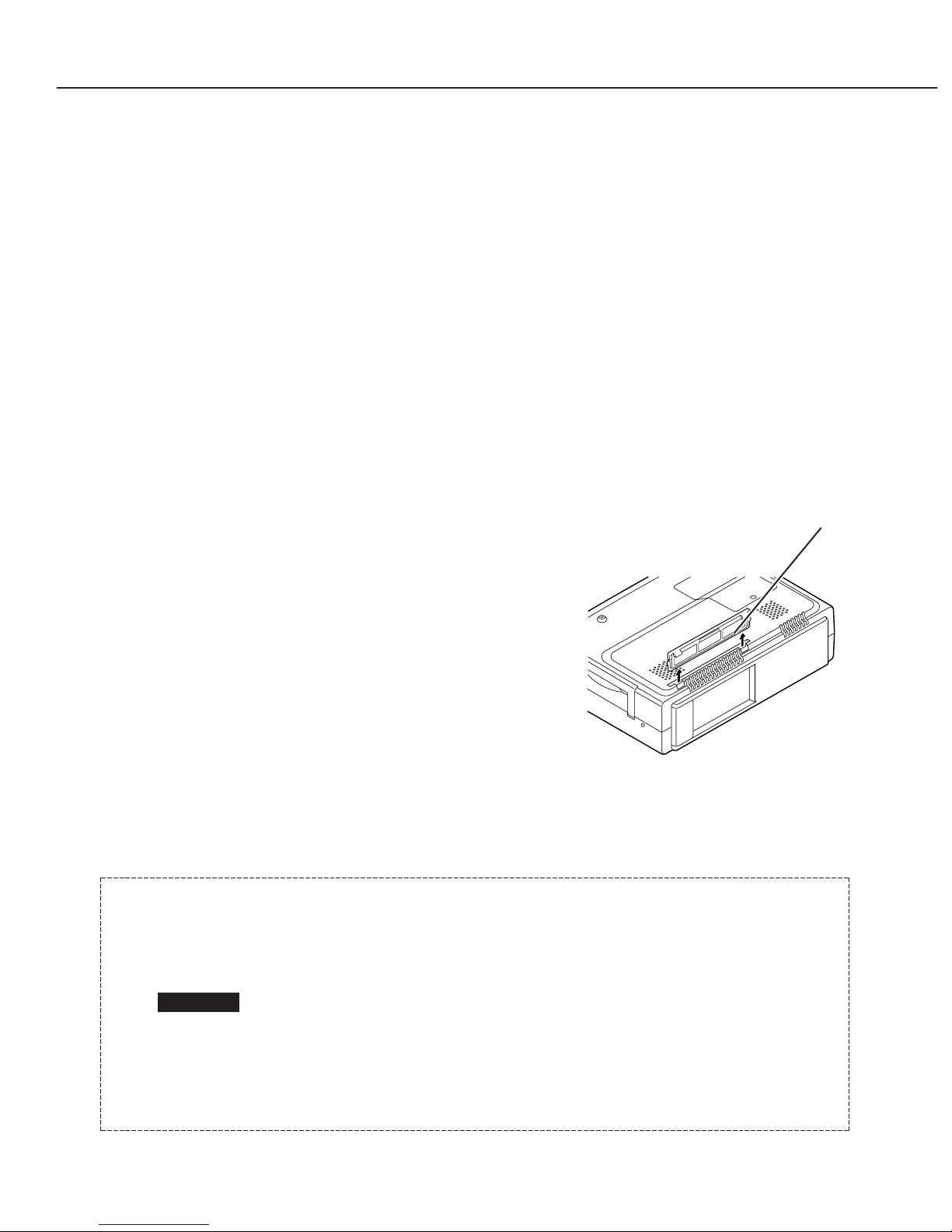
2.5 Air Filter Care and Cleaning
The removable air filter prevents dust from
accumulation on the surface of the projection lens
and projection mirror. Should the air filter become
clogged with dust particles, it will reduce the cooling
fan's effectiveness and may result in internal heat
build up and reduce the life of the projector.
To clean up the air filter, follow the cleaning
procedure below.
1. Turn the power off, and disconnect the AC power
cord from the AC outlet.
2. Turn the projector up side down and remove the
air filter by pulling its latches upward.
3. Clean the air filter with a brush.
4. Replace the air filter properly. Make sure that
the air filter is fully inserted.
Part 2: Repair Information
2-3
Air filter
Fig. 2-4
CAUTION
Do not operate the projector with the air filter removed. It may result
in the malfunction of the projector.
We recommend to avoid dusty, smoky place for operating the projector.
The dust is stuck on the LCD panel and the mirror, and it may spoil
the fine picture image.
Using in dusty place may cause the picture of poor quality.
When using under the dusty or smoky conditions, dust may
accumulate on the LCD panel and lens inside it, and may resultantly
be projected on the screen together with the picture.
When the above symptoms are noticed, please clean up the LCD panel
and lens according to the "Cleaning Method".
Part 2: Repair Information
2-4
3. SERVICE (MECHANICAL DISASSEMBLIES)
Mechanical disassemble should be made following procedures in numerical order.
Following steps show the basic procedures, therefore unnecessary step may be
ignored.
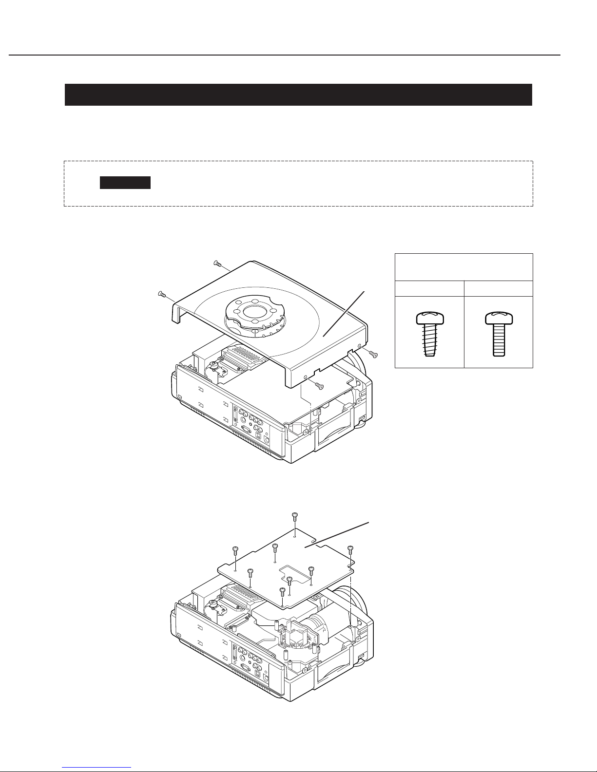
3.1 Cabinet Top and Control Panel Removal
1. Remove 4 screws A (M3 × 6) to take the Cabinet Top Ass’y upward off.
3.2 Main Board Removal
1. Remove 8 screws (M3 × 6) to take the Main Board upward off.
CAUTION
The parts and screws should be placed exactly the same position as
the original otherwise it may cause loss of performance and product
safety.
Fig. 2-6
Fig. 2-5
A
A
A
A
Cabinet top
Main Board
Screws Expression
(Type Diameter × Length) mm
T type M Type
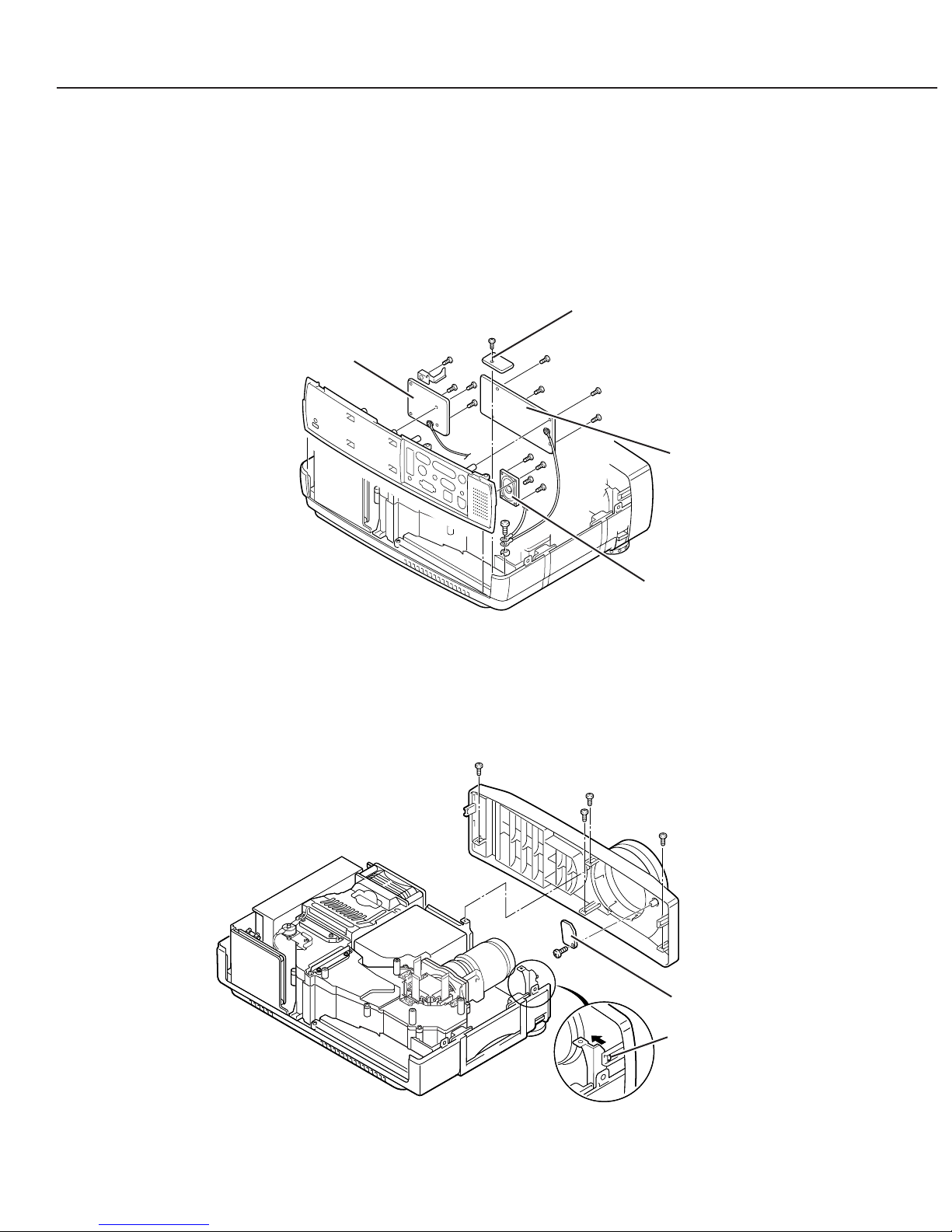
3.3 AV, DVI, Temp Board and Speaker Removal
1. Remove 1 screw A (M4 × 8) to release grounding wires.
2. Pull the Rear Panel ass'y upward.
3. Remove 4 screws B (T3 × 6) and remove the AV Board.
4. Remove 4 screws C (T3 × 6) and remove the DVI Board.
5. Remove 4 screws D (T2.6 × 6) and remove the speaker.
6. Remove 1 screws E (T3 × 8) and remove the Sensor Board.
3.4 Front Panel and R/C Board Removal
1. Remove 3 screws A (M3 × 4), 1 screw B (M3 × 8) and unhook 2 hooks C at the both of
left and right side, and the take the Front Panel ass’y off.
2. Remove 1 screw D (T3 × 8) to take the R/C Board off.
Part 2: Repair Information
2-5
Fig. 2-7
Fig. 2-8
A
A
A
B
C
D
R/C board
A
B
B
B
C
DVI board
AV board
Speaker
B
C
C
D
D
E
Temp board
 Loading...