

Canon D1, D2 Service Manual
Color Image Reader Unit - D1/D2
Product Outline
Technology
Periodic Servicing
Parts Replacement and Cleaning Procedure
Adjustment
Installation
Appendix
SERVICE MANUAL Rev4
654321

Application
This manual has been issued by Canon Inc. for qualied persons to learn technical theory,
installation, maintenance, and repair of products. This manual covers all localities where the
products are sold. For this reason, there may be information in this manual that does not
apply to your locality.
Corrections
This manual may contain technical inaccuracies or typographical errors due to improvements
or changes in products. When changes occur in applicable products or in the contents of this
manual, Canon will release technical information as the need arises. In the event of major
changes in the contents of this manual over a long or short period, Canon will issue a new
edition of this manual.
The following paragraph does not apply to any countries where such provisions are
inconsistent with local law.
Trademarks
The product names and company names used in this manual are the registered trademarks
of the individual companies.
Copyright
This manual is copyrighted with all rights reserved. Under the copyright laws, this manual may
not be copied, reproduced or translated into another language, in whole or in part, without the
written consent of Canon Inc.
© CANON INC. 2012
Caution
Use of this manual should be strictly supervised to avoid disclosure of condential
information.
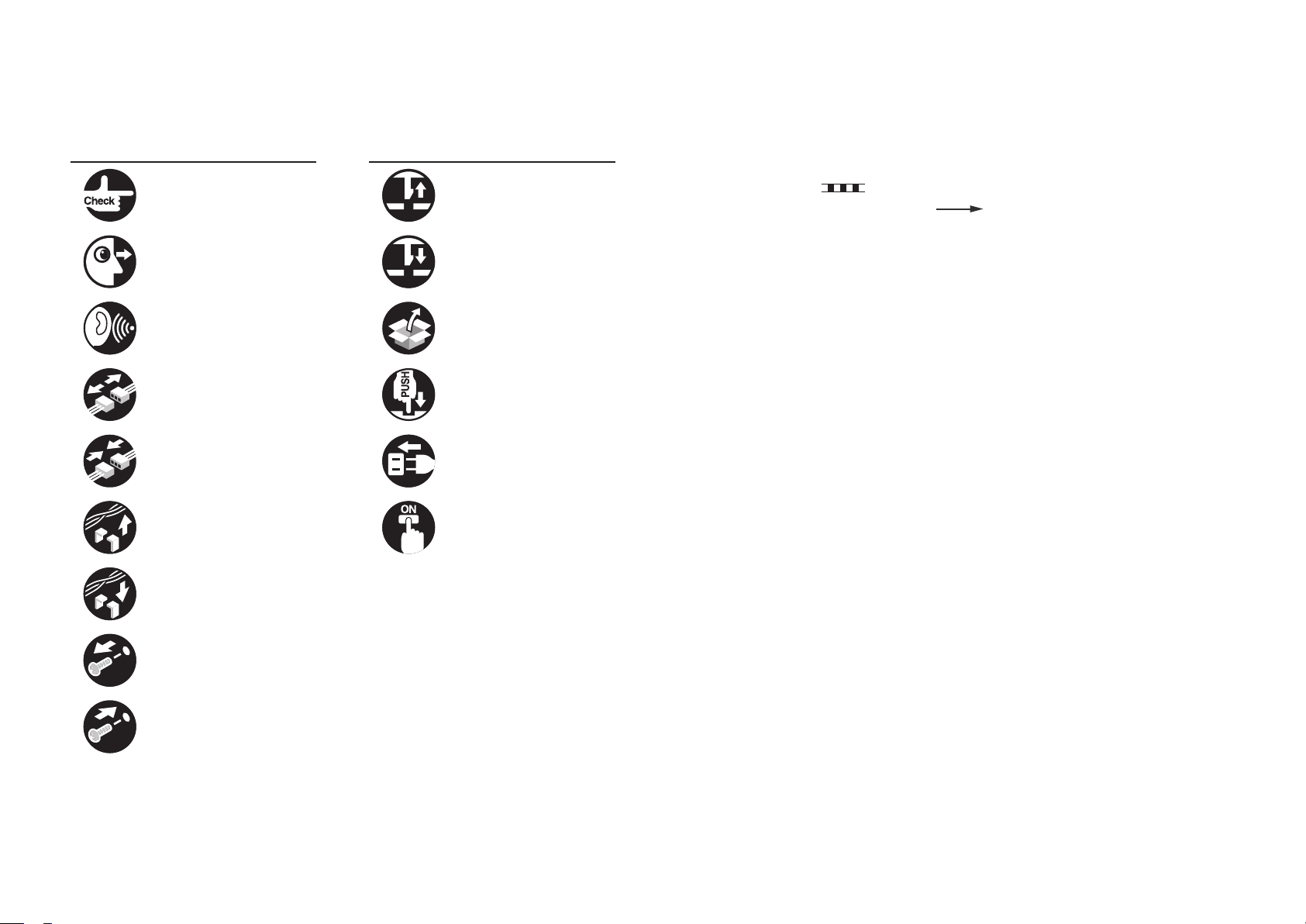
Explanation of Symbols
The following symbols are used throughout this Service Manual.
Symbols Explanation Symbols Explanation
Check. Remove the claw.
Check visually. Insert the claw.
The following rules apply throughout this Service Manual:
1. Each chapter contains sections explaining the purpose of specic functions and the
relationship between electrical and mechanical systems with reference to the timing of
operation.
In the diagrams,
accompanies the symbol, the arrow
represents the path of mechanical drive; where a signal name
indicates the direction of the electric
signal.
The expression "turn on the power" means ipping on the power switch, closing the
front door, and closing the delivery unit door, which results in supplying the machine with
power.
Check the noise. Use the bundled part.
Disconnect the connector. Push the part.
Connect the connector. Plug the power cable.
Remove the cable/wire
from the cable guide or wire
saddle.
Set the cable/wire to the
cable guide or wire saddle.
Remove the screw.
Tighten the screw.
Turn on the power.
2. In the digital circuits, '1' is used to indicate that the voltage level of a given signal is
"High", while '0' is used to indicate "Low". (The voltage value, however, differs from
circuit to circuit.) In addition, the asterisk (*) as in "DRMD*" indicates that the DRMD
signal goes on when '0'.
In practically all cases, the internal mechanisms of a microprocessor cannot be checked
in the eld. Therefore, the operations of the microprocessors used in the machines
are not discussed: they are explained in terms of from sensors to the input of the DC
controller PCB and from the output of the DC controller PCB to the loads.
The descriptions in this Service Manual are subject to change without notice for product
improvement or other purposes, and major changes will be communicated in the form of
Service Information bulletins.
All service persons are expected to have a good understanding of the contents of this Service
Manual and all relevant Service Information bulletins and be able to identify and isolate faults
in the machine.

Blank Page

Contents
0 Safety Precautions
Notes Before it Works Serving ---------------------------------------------0-2
1 Product Outline
Features (Reader) ------------------------------------------------------------1-2
Specications (Reader) ------------------------------------------------------1-2
Names of Parts (Reader) ---------------------------------------------------1-3
External View ----------------------------------------------------------------------- 1-3
Cross Section ----------------------------------------------------------------------- 1-3
Major Components ------------------------------------------------------------------------- 1-4
Reader Relay PCB ------------------------------------------------------------------------- 1-4
Features (DADF) --------------------------------------------------------------1-5
Specications (DADF) -------------------------------------------------------1-5
Names of Parts (DADF) -----------------------------------------------------1-6
External View ----------------------------------------------------------------------- 1-6
Cross Section ----------------------------------------------------------------------- 1-6
2 Technology
Technology (Reader) ---------------------------------------------------------2-2
Basic Sequence -------------------------------------------------------------------- 2-2
Basic Sequence at Power-On ----------------------------------------------------------- 2-2
Basic Sequence at Start Key ON (book mode/1 original) ------------------------ 2-2
Basic Sequence at Start Key ON (ADF mode/1 original) ------------------------- 2-2
Controls (Reader) -------------------------------------------------------------2-3
Controlling the Scanner Drive System ------------------------------------------------ 2-3
CCD -------------------------------------------------------------------------------------------- 2-4
Enlargement/Reduction ------------------------------------------------------------------- 2-6
Detecting the Size of Originals ---------------------------------------------------------- 2-6
Dirt Sensor Control ------------------------------------------------------------------------- 2-8
Image Processing -------------------------------------------------------------------------2-10
Reader Heater Control -------------------------------------------------------------------2-12
Basic Conguration (DADF) ---------------------------------------------- 2-13
Component Conguration ------------------------------------------------------2-13
Outline of Electric Circuits ---------------------------------------------------------------2-13
Sensor Layout ------------------------------------------------------------------------------2-14
Drive Conguration --------------------------------------------------------------- 2-14
Outline of Operation Modes ---------------------------------------------------- 2-15
Outline ---------------------------------------------------------------------------------------- 2-15
Forward Pickup/Delivery Operation ---------------------------------------------------2-15
Forward Pickup/Reverse Delivery Operation ---------------------------------------2-16
Controls (DADF) ------------------------------------------------------------- 2-18
Document Detection -------------------------------------------------------------2-18
Outline ---------------------------------------------------------------------------------------- 2-18
Initial Document Size Detection --------------------------------------------------------2-19
Detecting Jams -----------------------------------------------------------------------------2-19
Power Supply ----------------------------------------------------------------------2-20
Fan -----------------------------------------------------------------------------------2-20
3 Periodic Servicing
Work of Service (Reader) ---------------------------------------------------3-2
List of Work for Scheduled Servicing -------------------------------------------------- 3-2
Action to take when replacing parts ---------------------------------------------------- 3-2
Consumables -------------------------------------------------------------------------------- 3-2
Service precautions ------------------------------------------------------------------------ 3-2
Work of service (DADF) -----------------------------------------------------3-3
When replacing the parts -------------------------------------------------------- 3-3
Periodic Servicing ------------------------------------------------------------------ 3-3
List of Work for Scheduled Servicing (DADF) -------------------------3-4
4 Parts Replacement and Cleaning Procedure
List of Parts(Reader) ---------------------------------------------------------4-2
External Covers -------------------------------------------------------------------- 4-2
Main Units --------------------------------------------------------------------------- 4-2
List of Clutchs, Solenoids, Motors, Fans, PCBs --------------------------- 4-2
List of Sensors ---------------------------------------------------------------------- 4-2
Consumable Parts Requiring Periodic Replacement and Cleaning
Points --------------------------------------------------------------------------------- 4-2

External Covers(Reader) ----------------------------------------------------4-3
Removing the Reader Left Cover ---------------------------------------------- 4-3
Removing the Reader Front Cover -------------------------------------------- 4-3
Removing the Reader Right Cover -------------------------------------------- 4-3
Removing the Reader Rear Cover -------------------------------------------- 4-4
Main Units/Parts (Reader) --------------------------------------------------4-5
Removing the CCD Unit ---------------------------------------------------------- 4-5
Action to Take after Replacing the CCD Unit ---------------------------------------- 4-7
Removing the Platen Glass ----------------------------------------------------- 4-8
Action to Take after Replacing the Platen Glass ------------------------------------ 4-8
Removing the ADF Scan Glass ------------------------------------------------ 4-9
Action to Take after Replacing the ADF Scan Glass ------------------------------- 4-9
List of Parts(DADF) --------------------------------------------------------- 4-11
External Covers ------------------------------------------------------------------- 4-11
Consumable Parts Requiring Periodic Replacement and Cleaning
Points -------------------------------------------------------------------------------- 4-11
List of Clutchs, Solenoids, Motors, Fans, PCBs --------------------------4-12
List of Sensors ---------------------------------------------------------------------4-12
External Covers (DADF) -------------------------------------------------- 4-13
Removing the Front Cover -----------------------------------------------------4-13
Removing the Rear Cover ------------------------------------------------------ 4-13
Removing the Feeder Cover --------------------------------------------------- 4-14
Main Units (DADF) ---------------------------------------------------------- 4-15
Removing the Feed Unit --------------------------------------------------------4-15
Consumable Parts Requiring Periodic Replacement and Cleaning
Points (DADF) --------------------------------------------------------------- 4-16
Removing the Pickup Roller Unit ---------------------------------------------4-16
Removing the Separation Pad -------------------------------------------------4-17
Replacing the Stamp -------------------------------------------------------------4-17
Exchanging the Feed Roller Guide -------------------------------------------4-18
Clutch Solenoid Motor Fan PCB (DADF) ----------------------------- 4-19
Removing the ADF Motor(M1) -------------------------------------------------4-19
Removing the Release Motor(M2) --------------------------------------------4-19
Removing the Pressurization Solenoid(SL1) ------------------------------4-20
Pickup Clutch/Registration Clutch(CL1/CL2) -----------------------------4-20
Removing the ADF Driver PCB ------------------------------------------------4-21
Removing the LED PCB --------------------------------------------------------4-22
Removing the Fan ----------------------------------------------------------------4-22
Removing the Sensor(SR1,SR2,SR3) ---------------------------------------4-23
Removing the Timing Sensor(SR4) ------------------------------------------4-27
Removing the Document Set Sensor(SR5) --------------------------------4-27
Removing the Cover Open/Closed Sensor(SR6) -------------------------4-27
Removing the Last Document Detection Sensor(SR7) -----------------4-27
Removing the Document Length Sensor(SR8,SR9) --------------------- 4-28
Removing the Release Motor HP Sensor(SR11) -------------------------4-28
5 Adjustment
Image position adjustment(Reader) --------------------------------------5-2
Leading Edge Non-Image Width ----------------------------------------------- 5-2
Left Non-Image Width ------------------------------------------------------------ 5-2
Overview (DADF) -------------------------------------------------------------5-3
Adjustment Method (DADF) ------------------------------------------------5-3
Adjusting the Height --------------------------------------------------------------- 5-3
Pre-check ------------------------------------------------------------------------------------- 5-3
Checking the left hinge height ----------------------------------------------------------- 5-4
Adjustment Procedure --------------------------------------------------------------------- 5-5
Adjust the height of the left hinge ------------------------------------------------------- 5-5
Check the height of the right hinge ----------------------------------------------------- 5-5
Adjust the height of the right hinge ----------------------------------------------------- 5-5
Adjusting the Perpendicularity -------------------------------------------------- 5-6
Adjusting the Read Position ----------------------------------------------------- 5-7
Adjusting the Horizontal Registration ----------------------------------------- 5-7
Adjusting the Trailing Edge Registration ------------------------------------- 5-7
Adjusting the Magnication ------------------------------------------------------ 5-7
Adjusting the White Level -------------------------------------------------------- 5-8
6 Installation
How to Utilize This Installation Procedure ------------------------------6-2
Illustrations Used in This Procedure ------------------------------------------ 6-2
Descriptions Used in This Procedure ----------------------------------------- 6-2
When Using the Contained Parts (Bundled Components in the Shipping
Carton) -------------------------------------------------------------------------------- 6-2

Symbols in the Illustration ------------------------------------------------------- 6-2
Caution During Installation --------------------------------------------------6-3
Turning OFF the Host Machine Power ----------------------------------6-3
Checking the Contents ------------------------------------------------------6-4
Installation Procedure --------------------------------------------------------6-5
Operation Check ------------------------------------------------------------ 6-16
Appendix
Service Tools ----------------------------------------------------------------------ii
Solvents and Oils ------------------------------------------------------------------------------ ii
Special Tools ------------------------------------------------------------------------------------ ii
General Circuit Diagram(DADF) -------------------------------------------- iii
General Circuit Diagram ---------------------------------------------------------------------iii
General Circuit Diagram(Reader) ------------------------------------------- iv
General Circuit Diagram ------------------------------------------------------------iv
Signal Name List(Reader) -----------------------------------------------------v
Signal Name List(DADF) ------------------------------------------------------ vi
Signal Name List -------------------------------------------------------------------------------vi

Safety Precautions
Notes Before it Works Serving
■

0
Safety Precautions > Notes Before it Works Serving
Notes Before it Works Serving
Caution:
At servicing, be sure to turn off the power source according to the specied steps and
disconnect the power plug.
Caution:
Do not turn off the power switch when downloading is under way.Turning off the main
power switch while downloading is under way can disable the machine.
0-2
Safety Precautions > Notes Before it Works Serving
0
0-2
Product Outline
1
Features (Reader)
■
Specications (Reader)
■
Names of Parts (Reader)
■
Features (DADF)
■
Specications (DADF)
■
Names of Parts (DADF)
■
Product Outline
1

1
Product Outline > Specications (Reader)
1-2
Features (Reader)
• Adapting Reading sensor, allows low power consumption and high-speed trigger.
• Exposure to light by white color LED, enables low power consumption, size reducing, and
color balance improvement.
• Color aberration-free.
Specications (Reader)
The major specications, controls and functions of the original exposure system are described
below.
Item Specication/function
Original exposure
Original scan In book mode
In ADF mode
Maximum original size
Read resolution
Gradation
Carriage position detection
Magnication
Main scanning
direction
Sub scanning
direction
Lens
CCD
CCD unit drive control
Original size
detection
In book mode
Indirect exposure by LED (LED & photoconductive body)
Scan by movement of CCD
Stream reading with CCD xed
297mm x 432mm (In book mode)
600 dpi (main scanning) x 600 dpi (sub scanning)
256 gradation
CCD HP sensor (SR1)
25% to 400%
Image is processed on main controller PCB 2
Image is processed on main controller PCB 2
Gauss lens
Number of lines: 4 (R, G, B, B/W)
Number of pixels: 7500 x 3 color lines, 7500 x 1 B/W line
Maximum original read width: 304mm
By scanner motor (M1)
Main scanning direction: by CCD
Sub scanning direction: by reection sensor (AB/INCH)
Product Outline > Specications (Reader)
1
In ADF mode
Main scanning direction: by photo interrupter on DADF
Sub scanning direction: by photo interrupter on DADF
T-1-1
1-2
1
Product Outline > Names of Parts (Reader) > Cross Section
1-3
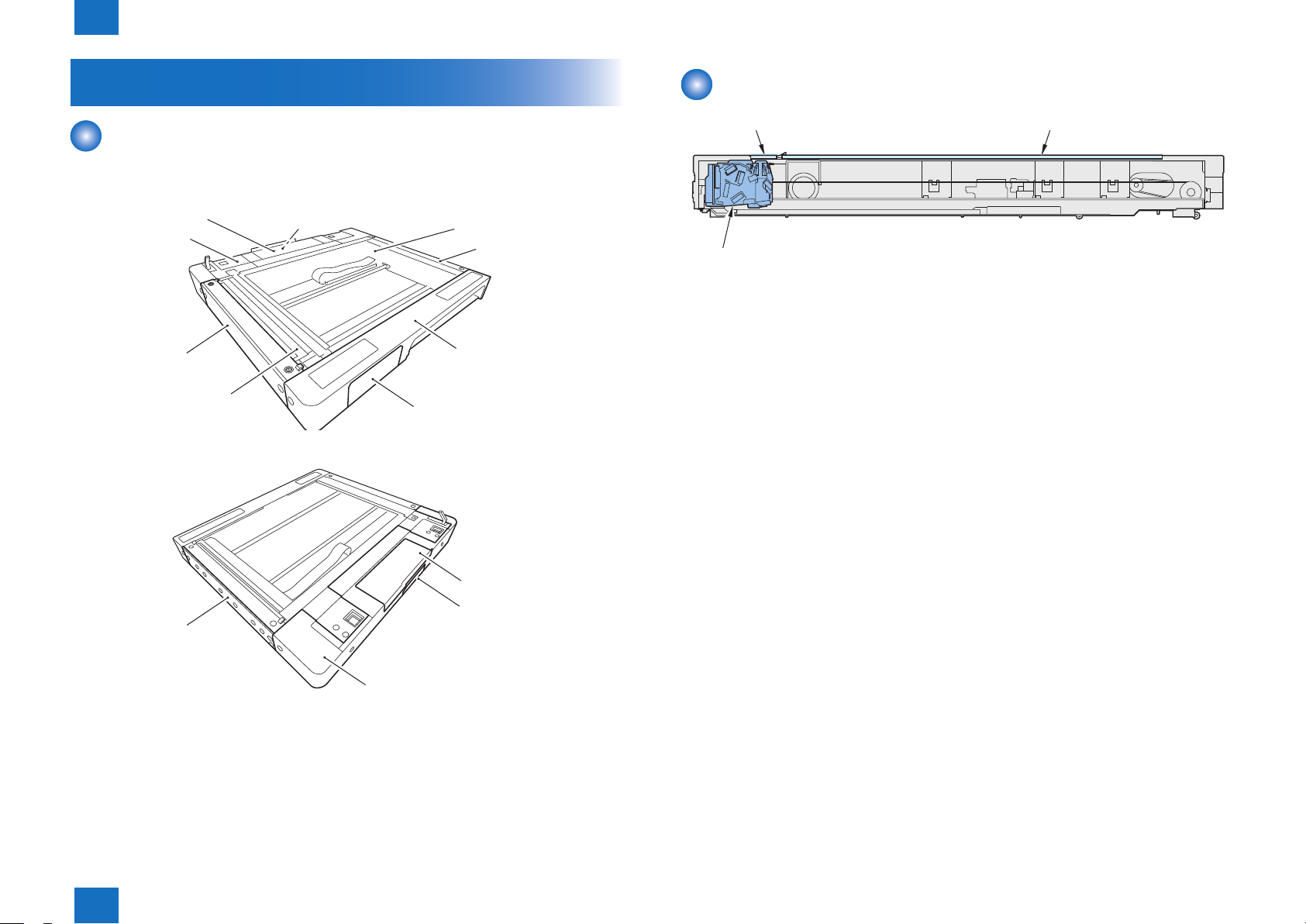
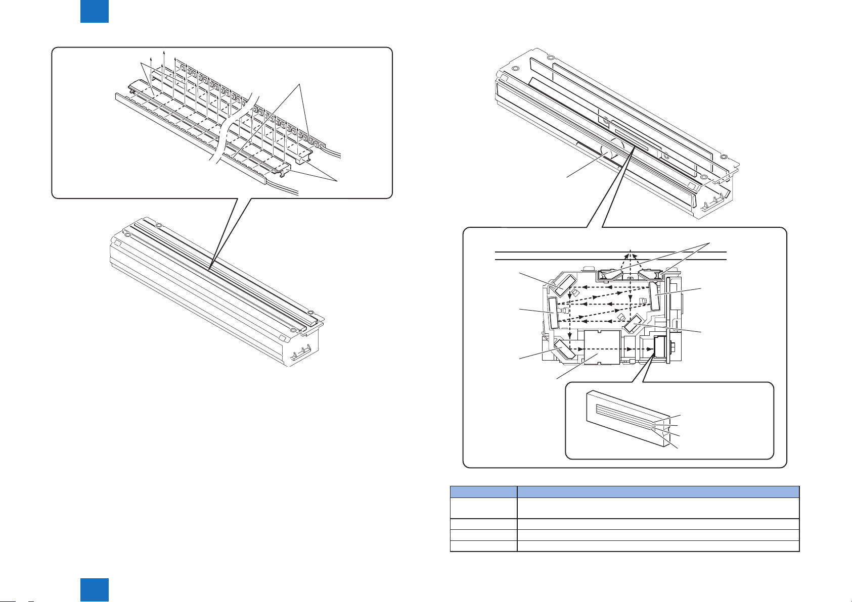
Names of Parts (Reader)
External View
[5]Reader PCB Cover
[4]Reader Rear Cover
[3]Reader Left Cover
[10]Stream Read Glass
[6]Rear Small Cover
[9]Copyboard Glass
[7]Reader Right Cover
[1]Reader Front Cover
[2]Reader Front Sub Cover
F-1-1
Cross Section
Stream reading glass
CCD unit
Copyboard glass
F-1-3
Reader Right Cover
Product Outline > Names of Parts (Reader) > Cross Section
1
Reader PCB Cover
Connector Cover
Reader Rear Cover
F-1-2
1-3
1
]Original Size Sensor 1
Product Outline > Names of Parts (Reader) > Cross Section > Reader Relay PCB
1-4
■Major Components
Following shows major components of document exposure system.
[SR3]Copyboard Cover
Open/Closed Sensor(Front)
[SR2]Copyboard Cover
Open/Closed Sensor(Rear)
[SR1]CCD HP Sensor
[H5]Reader Heater(Option)
[PCB1]Relay Board
Item Notation Specication/function
Scanner motor M1 Pulse motor: controls the carriage drive
CCD HP sensor SR1 Detects CCD home position
Copyboard Cover Open/Closed
Sensor (front)
Copyboard Cover Open/Closed
Sensor (rear)
SR2 Ends original size identication with the copy board
cover at 15 deg
SR3 Detects the copyboard cover open/close. Starts original
size identication with the copy board cover at 5 and 25
deg.
Original Size Sensor 0 SR4 Helps identify original size(AB, INCH/AB, A)
Original Size Sensor 1 SR5 Helps identify original size(INCH/AB, INCH/A)
CCD unit - Indirect exposure by LED (LED & photoconductive
body)
Reader Heater (Option) H5 Prevents condensation on the copyboard glass
Reader relay PCB PCB1 The part of the image processing
[M1]Scanner Motor
[H5]Reader Heater(Option)
[SR5
[SR4]Original Size Sensor 0
[8]CCD Unit
F-1-4
T-1-2
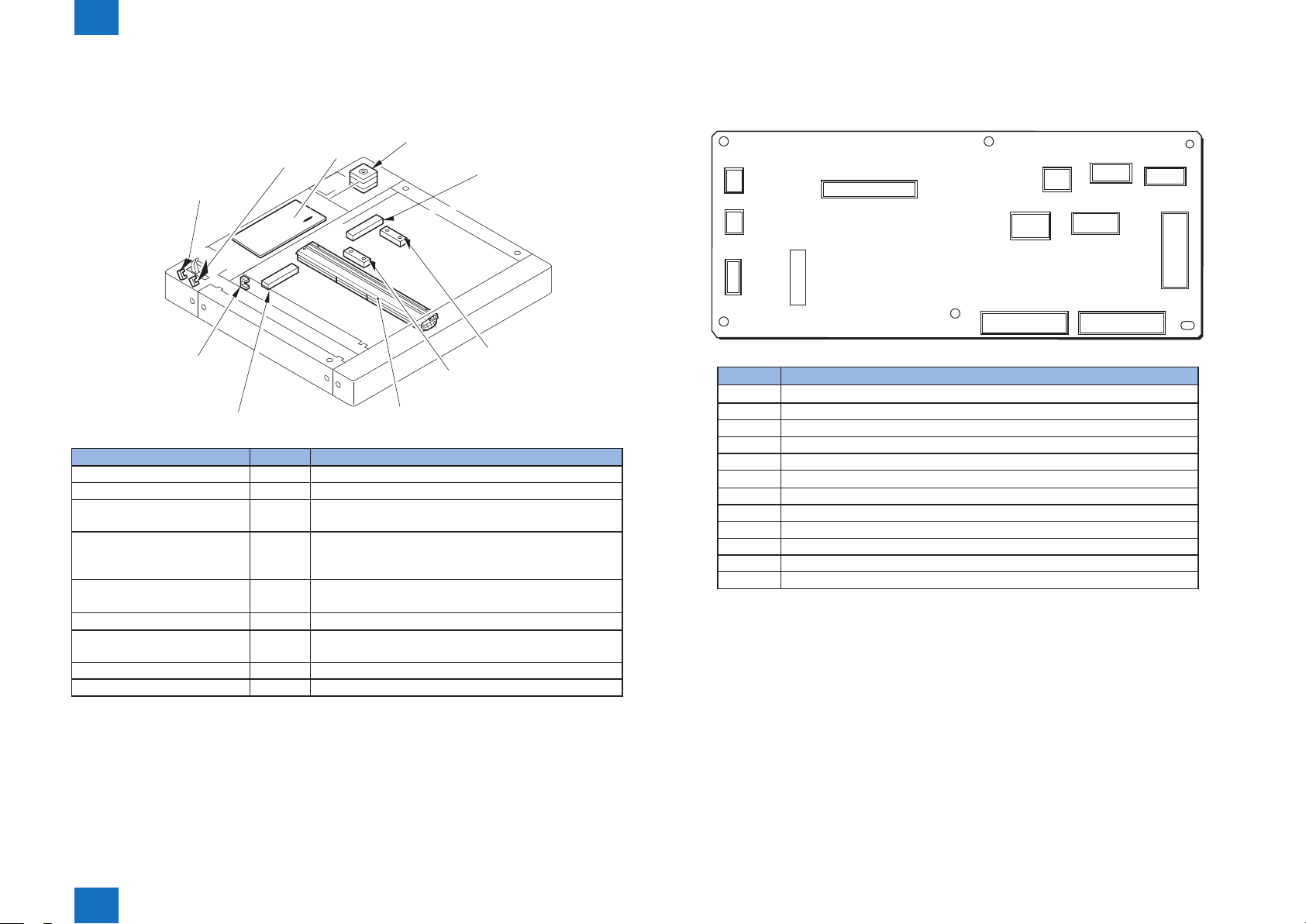
■Reader Relay PCB
The function conguration of reader controller PCB is described below.
J511
J501
J508
J502
J505
IC501
Jack No Description
J501 Connection to original size sensor
J502 Connection to original size sensor
J503 Power supply to DADF
J504 Communication with DADF
J505 Connection to Scanner motor
J506 Connection to original size sensor
J507 Communication with main controller PCB 2
J508 Communication with CCD
J509 Communication with DADF
J510 Connection to copyboard cover open/close sensor and CCD HP sensor
J511 Receives power from the host machine (printer unit)
J512 Communication with main controller PCB 2
J503
J509
J507
J506
J510
J504
J512
F-1-5
T-1-3
Product Outline > Names of Parts (Reader) > Cross Section > Reader Relay PCB
1
1-4

1
Product Outline > Specications (DADF)
1-5
Features (DADF)
• Mixed size loading mode enables the feeder to handle the different width originals in a job.
• New body shape and color.
• Interface cable is wired inside the body.
Specications (DADF)
Item Specications
Document pickup method Automatic pickup and delivery
Document loading direction Face-up
Document loading position Aligned to center
Document separation method Upper separation
Document type Single -sided AB type: 42-128 g/m2
Inch type: 50-128 g/m2
Double-sided 50-128 g/m2
Color document 64-128 g/m2
Black and White/
Color Mixed
Document longer
than 432 mm
Document size AB type: B6/A5/B5/A4/B5R/A5R/A4R/B4/A3 (B6:Cross feed
Document tray capacity 50 sheets (80g/m2)
Document processing mode - Single-sided document processing
Document size recognition Available (Standard size)
Mixed document function Same types of paper can be mixed.
Book document Supported (The document thickness must be 50 mm or less.)
Interface with Install Connected
Equipment
Power supply Supplied from host machine
Dimensions 565 mm×510 mm×145 mm (W×D×H)
Weight Approx. 7.9 kg
50-128 g/m2 (Color:64-128 g/m2)
Single-sided one sheetFeed: 60- 90g/ m2
only)
INCH type: STMT/LTR/LTRR/LGL/11"×17" (STMT:Cross feed
only)
Others:8K/16K
Document width: 148-297mm
Document length (longitudinal): 128-432mm (“630mm” is held by
the operator.)
- Double-sided document processing
Different types of paper can be mixed.
Different types original mixable combination:
A/B type: A3/B4R,A4/B5,B4/A4R,B5/A5,A4R/B5R,A5/B6
Inch type: LDR/LGL,LTR/LGL,LTR/STMT
Cereal Interface
T-1-4
Product Outline > Specications (DADF)
1
1-5
1
Product Outline > Names of Parts (DADF) > Cross Section
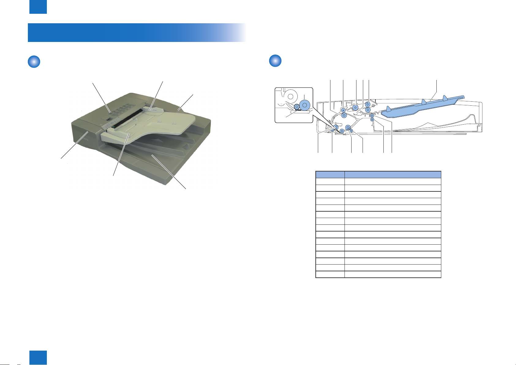
Names of Parts (DADF)
1-6
External View
Feeder Cover
Front Cover
Document supply tray
Slide guide
Rear Cover
Document delivery tray
F-1-6
Cross Section
[11]
[13]
[12]
[1] [2]
No. Part name
[1] Lower registration roller
[2] Upper registration roller
[3] Feed roller
[4] Separation pad unit
[5] Pickup roller
[6] Document supply tray
[7] Upper delivery reversal roller
[8] Lower delivery reversal roller
[9] Read roller 2 (lower)
[10] Read roller 2 (upper)
[11] Platen roller
[12] White sheet
[13] Read roller
[14] Read roller 1 (lower)
[15] Read roller 1 (upper)
[3] [5][4] [6]
[7][8][9][10][15] [14]
F-1-7
T-1-5
Product Outline > Names of Parts (DADF) > Cross Section
1
1-6

Technology
2
Technology (Reader)
■
Controls (Reader)
■
Basic Conguration
■
(DADF)
Controls (DADF)
■
2
Technology

2
Technology > Technology (Reader) > Basic Sequence > Basic Sequence at Start Key ON (ADF mode/1 original)
2-2
Technology (Reader)
Basic Sequence
■Basic Sequence at Power-On
ON STBY
( )
Scanner motor
(LED)
(CCD
HPsensor)
Footnote
• F: Scanner motor moves forward (toward right).
• B: Scanner motor moves backward (toward left).
• Light-ON: LED on CCD unit lights-on.
• ON: When CCD HP sensor (photo interrupter type) detects.
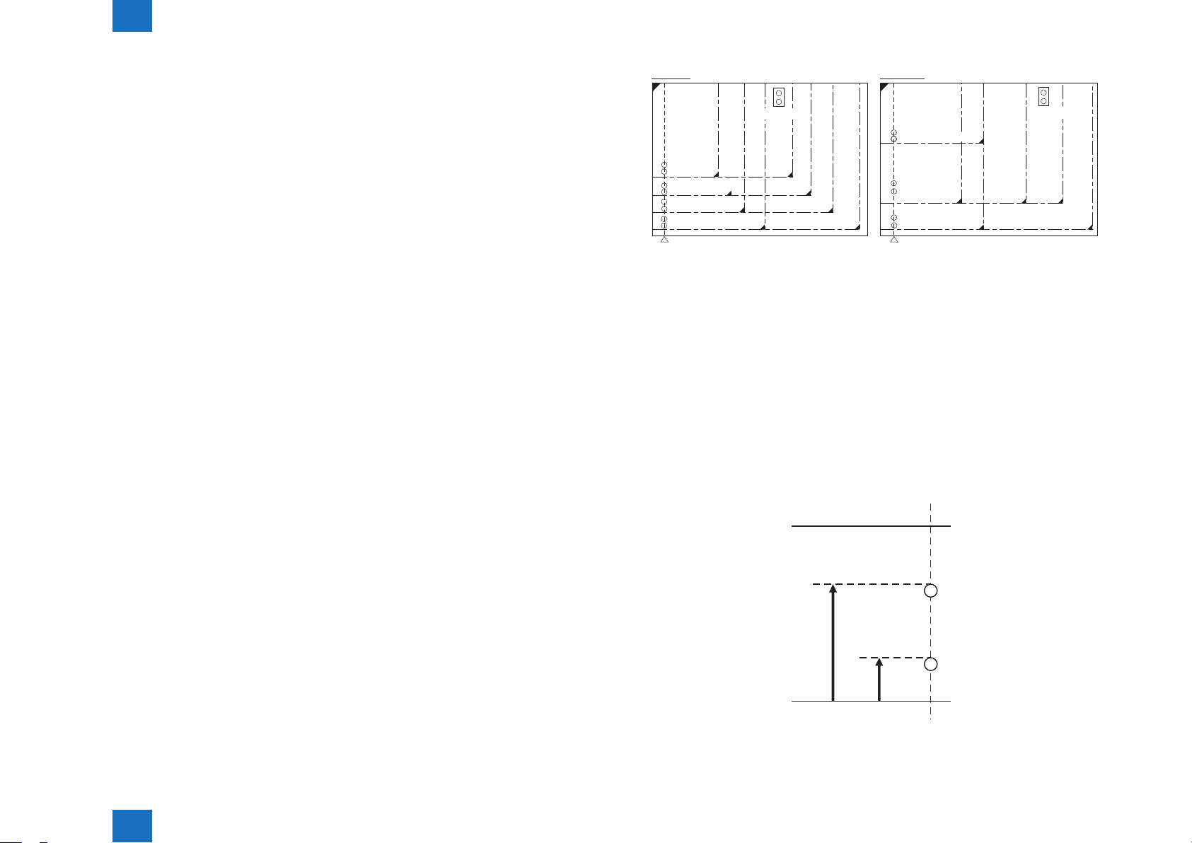
■Basic Sequence at Start Key ON (book mode/1 original)
B F
Light-ON
ON
CCD adjustment
F-2-1
■Basic Sequence at Start Key ON (ADF mode/1 original)
Copy start
(Scanner motor)
(LED)
(CCD HP
sensor )
Dust detection control
This is activated when any of the following conditions is true.
• Dust has been detected in all 3 locations at previous 1 job.
• Dust detection could not be activated due to JAM etc at previous job.
Footnote
• F: Scanner motor moves forward (toward right).
• B: Scanner motor moves backward (toward left).
• Light-ON: LED on CCD unit lights-on.
• ON: When CCD HP sensor (photo interrupter type) detects.
Dust detection control
B F F F B F
Light-ON
ON
Shading correction
White board duct detection control
In stream reading
B B
F F F F
Light-ON
End
F-2-3
Copy start
(Scanner motor)
(LED)
(CCD HP
sensor )
B
White board duct detection control
In reading
F
Light-ON
ON ON
B
Shading correction
Footnote
• F: Scanner motor moves forward (toward right).
• B: Scanner motor moves backward (toward left).
• Light-ON: LED on CCD unit lights-on.
• ON: When CCD HP sensor (photo interrupter type) detects.
Technology > Technology (Reader) > Basic Sequence > Basic Sequence at Start Key ON (ADF mode/1 original)
2
End
F
F-2-2
2-2
2
Technology > Controls (Reader)
2-3
Controls (Reader)
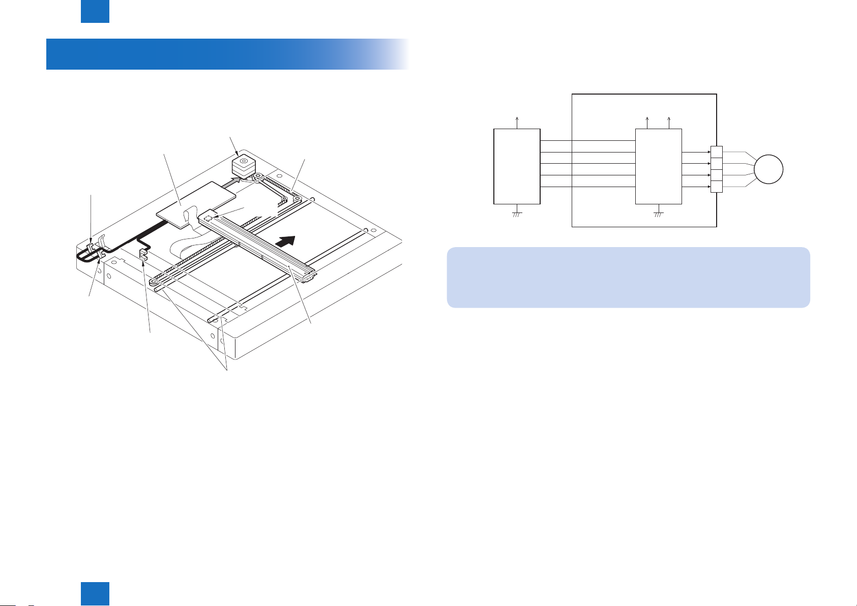
■Controlling the Scanner Drive System
●Overview
Parts conguration of scanner drive is described below.
Scanner motor (M1)
Reader relay PCB (PCB1)
Copyboard cover
open/closed sensor (SR3)
Sensor light
block plate
Backward
Copyboard cover
open/closed sensor (SR2)
CCD HP sensor (SR1)
Carriage drive belt
Forward
CCD unit
●Scanner Motor Control
Scanner motor driver turns on/off the motor and controls its direction/speed of rotation
according to the signals from CPU.
Main controller PCB 2
3.3V +24V
OPM_ENB
OPM_CLK
CPU
OPM_CWB
MOT_VREF
OPM_STB
NOTE:
The scanning speed of this machine is as follows.
Black/white (600dpi x 600dpi):30ipm
Color (600dpi x 600dpi):30ipm
Reader relay PCB
+5V
Motor
driver
A*
1
B*
2
A
3
B
4
M1
F-2-5
Guide shaft
- Scanner motor (M1) drive signal
Turns on/off the motor and controls its direction/speed of rotation.
- CCD HP sensor (SR1) detection signal
Checks if CCD is at home position.
- Copyboard cover open/closed sensor (front: SR2/rear: SR3) detection signal
Detects the open/close status of the copyboard cover
Technology > Controls (Reader)
2
F-2-4
2-3
2
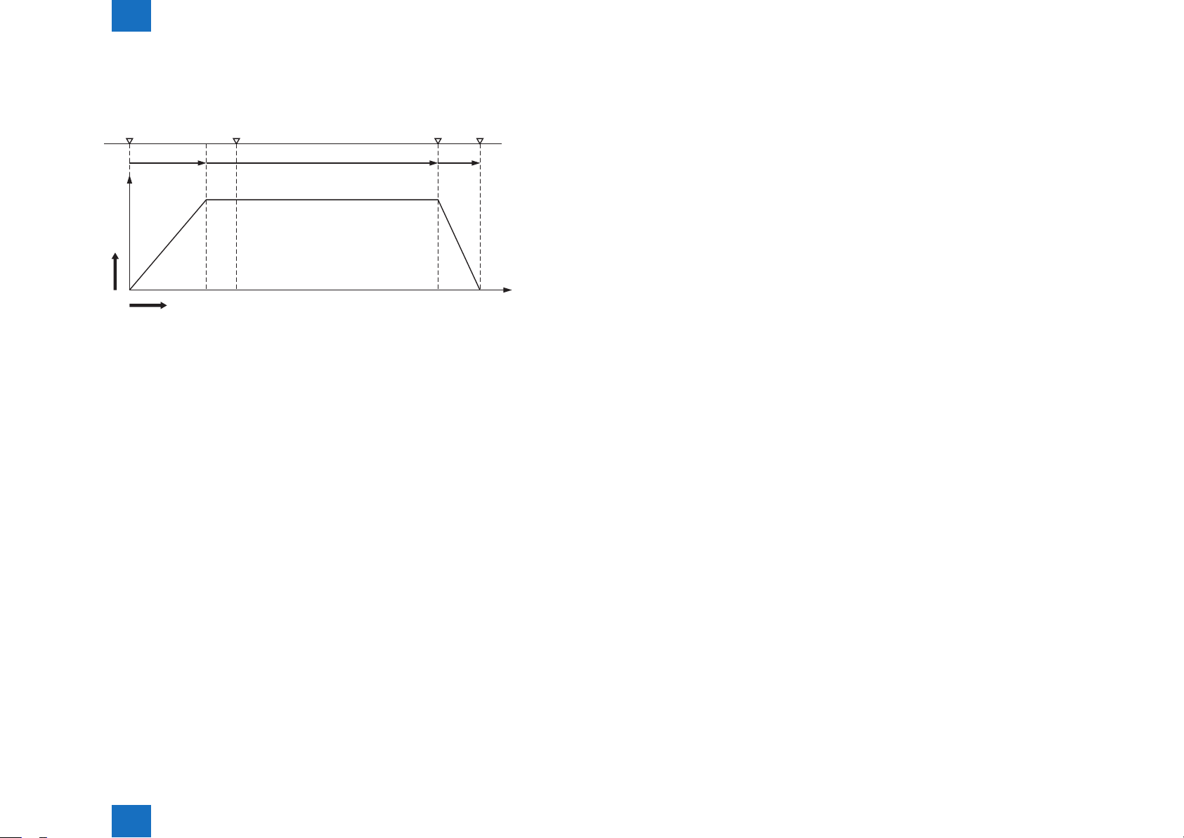
Acceleration area: Accelerates until a speed suited to the selected mode is reached
Deceleration area: Decelerates and stops promptly once the image end is reached.
Technology > Controls (Reader)
2-4
1) Forward movement when scanning an image
CCD operation is controlled by the following sensors when scanning the image.
Start position
position
Acceleration
Shift
speed
[1] [2] [3] [4]
Shift distance
2) Backward movement after scanning an image
After scanning an image, CCD moves backward to CCD shading position at a specic
speed (260 mm/sec).
Original
leading edge
Normal speed
[1]
[2]Run-up speed area: Run-up margin to ensure a stable speed.
[3]Image reading area: Reads an image at a specific speed.
[4]
Original
trailing edge
Stop
Deceleration
F-2-6
■CCD
●Overview
The machine uses the CCD to expose and read an image and the image is read on a line-by-
line basis.
CCD features 4 lines (R, G, B, B/W) and B/W line is used in B/W copy and R, G, B lines are
used at color scan.
CCD overview
1. Integrated scanning conguration; CCD, lens, light source and mirror are integrated.
2. CCD elemental size: 4.7 μm
3. Lens diameter: 18mm dia
4. Light source: LED
5. Effective number of pixel: 7500 pix x 3 color lines, 7500 pix x 1 B/W line
[Optical path from LED]
The light generated from LED is reected by an original and by the 5 mirrors. And then it is
irradiated to the CCD through the lens.
Technology > Controls (Reader)
2
2-4
2
Technology > Controls (Reader)
LED lens cover
2-5
LED (light source)
Photoconductive
body
F-2-7
mirror
No.4
mirror
No.2
mirror
No.5
Lens
LED (light source)
mirror No.3
mirror No.1
Lens
CCD
Black & White (B/W) line
Red (R) line
Green (G) line
Blue (B) line
Technology > Controls (Reader)
2
F-2-8
Items Description
CCD Receives the reected light that has gone through the lens and converts it into
electric signal to output it.
Lens Collects the light reected by an original.
LED(light source) Light source to expose an original to laser
mirror No. 1 - 5 Return the light
T-2-1
2-5
2
Technology > Controls (Reader)
2-6
■Enlargement/Reduction
●Magnications in Main Scanning Direction
In book mode/ADF mode
An image is read at 100% in main scanning direction. Magnication variation and its data
process are controlled on main controller2 PCB.
●Magnication in Sub Scanning Direction
In book mode/ADF mode
An original is read at 140mm/s and the data is processed by the main controller PCB 2.
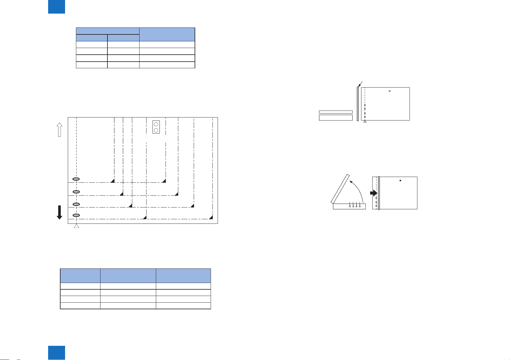
■Detecting the Size of Originals
●Overview
The machine identies the original size by the combination of measurement result of reection
light from the reection sensor and specic points of CCD. Also to identify it accurately even
though an original moves when ADF is closed, the machine measures 2 points for each size.
- Main scanning direction: CCD
- Sub scanning direction: Reection type photo sensor (AB type: 1 point, inch type: 1 point )
The followings are the procedures of original size identication.
1) External light search (main scanning direction only)
According to the LED status, the machine identies the CCD level of each detection
position in main scanning direction.
2) Output level detection of each sensor
The machine turns on the LED on CCD unit and measures the CCD level of each detection
position in main scanning direction.
Also, turns on the LED on reection type photo sensor in sub scanning direction and
measures the sensor output.
AB type
Original detection
position 1
B6
Original detection
position 2
Original detection
position 3
Original detection
position 4
CCD original detection position
A5
B5
Original sensor 0
B5R
A4R
B4
A4
Inch type
Original detection
position 1
Original detection
position 2
Original detection
A3
position 3
CCD original detection position
STMT
STMTR
LTR
LTRR
Original sensor 1
LGL
279.4×431.8mm
(11"×17")
F-2-9
1. 2 points original detection at each detection position
For each point of measurement in main scanning direction, the machine checks the
presence/absence of an original with reference to the CCD output at 2 points near the point
of measurement.
* The machine checks if the signal is changed or not from ADF (pressure plate) open to
close at both points of 1A and 1B.
Change in the signal: Yes
Change in the signal: No
Judgment is done by the measurement results of 1A and 1B, and it indicates the presence
of original if either point shows absence (absence). It indicates absence
of original if both signals show Yes (presence).
Borderline of
original size
approx 13mm
1A=additional
detection point 1
The original size is identied by the combination of these output result.
●Control Details
For main scanning direction, the machine moves the CCD unit to the following CCD original
detection positions according to the location of original to measure the CCD level of each
detection position. For sub scanning direction, the machine uses the original sensor 0, 1 to
identify sizes.
Technology > Controls (Reader)
2
Borderline of
original size
approx 4mm
1B=conventional
detection point 2
F-2-10
2-6
2
Technology > Controls (Reader)
2-7
Change Result of detection
1A 1B
Yes Yes Original absence
No Yes Original presence
Yes No Original presence
No No Original presence
T-2-2
2. Priority on the front sensor
When checking the measurements for main scanning direction, if the absence of an original
is indicated at the rear while the presence of an original is indicated at the front, the machine
will give priority to the indication at the front.
Rear
side
Original sensor 0
Position of
detection 1
Position of
detection 2
Position of
detection 3
B5
Position of
detection 4
Front
side
CCD original
detection position
F-2-11
In case of B5 size original
Position of
detection
1 Yes Yes
2 No Yes
3 Yes Yes
4 No No
Result of detection Result of
identication
T-2-3
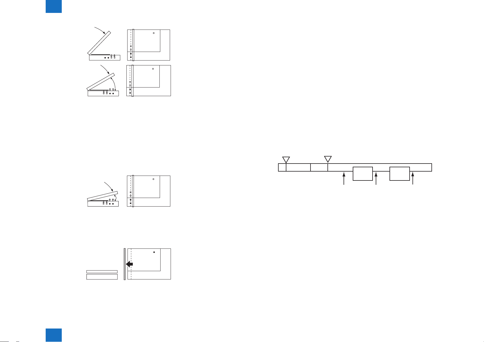
●Detection Operation Overview
1) Standby state (The following is in case that the AB type, A4R size is set.)
CCD unit: shading position
LED: OFF
Original sensor: OFF
CCD unit
ADF
Reader unit
Position of detection 1
Position of detection 2
Position of detection 3
Position of detection 4
original detection position
CCD
2) ADF opened
CCD unit: moves to original detection position
LED: OFF
Original sensor: OFF
(External
light)
3) ADF closed
CCD unit: in original detection position
LED: OFF to ON
Original sensor: in original detection operation
- With the ADF angle at 25 deg or less, the external light is blocked at the original width
area. Then, the machine determines that the original is absent at the points that the
external light is detected (external light search operation). When the original mount sensor
(rear) detects [close], original size detection is started. In this case, B5/B4/A4/A3 size is
eliminated at this point.
- After external light search, LED is turned ON at main scanning side and the CCD checks
the reection light (4 points). For sub scanning direction, original sensor detects the size.
Original sensor
Copyboard glass
F-2-12
F-2-13
Technology > Controls (Reader)
2
2-7
2
Technology > Controls (Reader)
2-8
■Dirt Sensor Control
(External
light)
F-2-14
25°
F-2-15
4) ADF fully closed (5 deg or less)
CCD unit: in original detection position
LED: ON
Original sensor: in original detection operation
- For 2 sec from the original mount sensor (front) detected [close], this monitors the
changes of output level of each sensor. The machine determines that the original is
present in the position where the level is not changed.
The machine identies the original size by the combination of level changes at 5 points (in
case of AB type size).
5°
F-2-16
5) Standby status (waiting for start key)
CCD unit: in original detection position
LED: OFF
Original sensor: OFF
●Overview
The machine changes the original read point or executes image correction depending on
the presence/absence of dust on the stream reading glass or the platen roller of the ADF to
prevent the dust from showing up in the output. These operations are carried out only when
the ADF is in use and, in addition, is closed.
[Control timing]
- At the end of a job
- Between sheets (for each reading of a sheet)
- At the start of a job (only when any of the following conditions is true.)
Dust detected at all points of detection at the end of the previous job
Dust detection failed to end normally at the end of the previous job (e.g., ADF opened)
Main power
switch
ON
WMUP
Start key
ON
STBY
Dust detection
control
1st
SCAN
Dust detection
control
2nd
SCAN
Dust detection
control
F-2-18
Technology > Controls (Reader)
2
F-2-17
2-8
2
Technology > Controls (Reader)
2-9
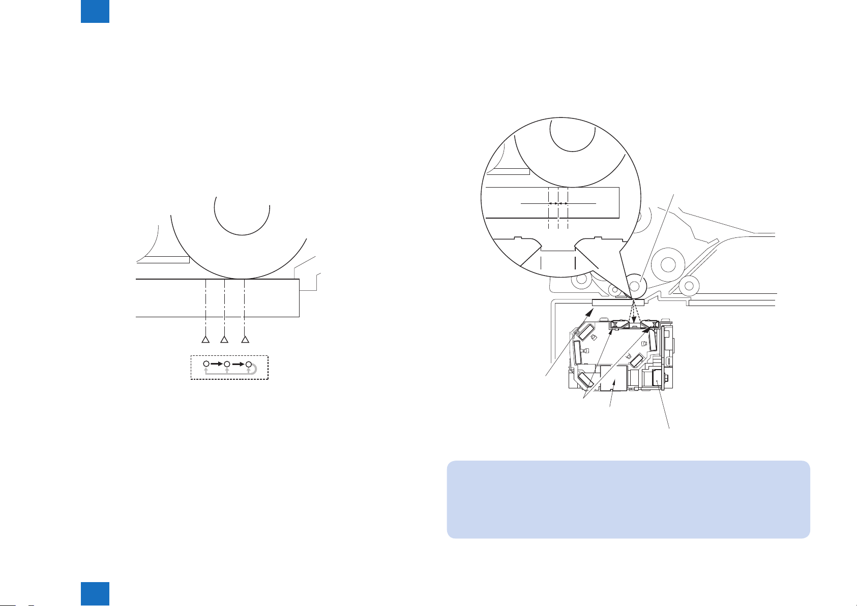
[Particulars of control]
- At the end of a job (dust detection)
CCD checks the light reected by the surface of the platen roller of the ADF at the read
point to detect the presence/absence of dust. Presence of dust is detected at points A, B,
and C in this order. The point where least dust is detected will be used as the read position
for the next job.
The point selected here will be used as the read position for the next job.
- At the start of a job (dust bypass)
Presence of dust is detected at points A, B, and C in this order in the same manner as at
the end of the job. Read will take place at the point where least dust is detected.
- Between sheets
The machine does not move CCD.
It reads the original using the position determined at the end or start of a job; however,
if the presence of dust is still detected at the position, the machine will execute image
correction.
Platen roller
0.5mm0.5mm
A B C
Technology > Controls (Reader)
2
A
B C
F-2-19
Stream
reading glass
LED
Lens
Service Mode
(Lv1) COPIER > OPTION > IMG-RDR > DFDST-L1
(used to adjust the dust detection level between sheets)
(Lv1) COPIER > OPTION > IMG-RDR > DFDST-L2
(used to adjust the dust detection level at the end of a job)
CCD
F-2-20
2-9
2
Technology > Controls (Reader)
2-10
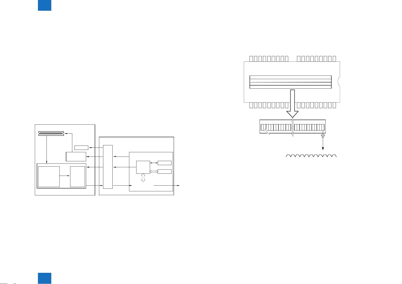
■Image Processing
●Overview
The functions of image processing system’s PCB are described below.
- Main controller PCB 2 CCD drive, analog image process, A/D conversion, shading
correction (executed per each job), shading adjustment (executed at
power-on)
- CCD PCB Analog image process, A/D conversion
The machine uses the main controller PCB to process images for every single image line.
Specic functions are as follows.
a. Main controller PCB 2
- Shading correction
b. CCD PCB (inside CCD unit)
- CCD drive
- CCD output gain correction, offset correction
CCD PCB
CCD(4lines )
Analog image
signal
Analog image
process
- gain correction
- offset
correction
CCD/AP PCB
EEP-
CCD drive
control
A/D
conversion
ASIC
ROM
CCD
control
signal
Gain
correction
data
Digital
image
signal
Main controller PCB 2
CPU
Shading
correction/
adjustment
EEP-
ROM
SRAM
Digital image
signal
●CCD Drive
The machine's CCD sensor is a 4-line linear image sensor consisting of 7500 pixels. After
completion of photoelectric conversion in the light-receiving block, the signals are output to
the analog front end PCB unit on CCD PCB in parallel for each channel (R, G, B, B/W) of the
CCD array.
Red(R)line
Green(G)line
Blue(B)line
Black & white(B/W)line
Expanse
Light-receiving block
Output
F-2-22
●Gain Correction and Offset Correction of CCD Output
The analog video signal generated by the CCD is corrected so that it will have a specic level
(gain correction); moreover, the output voltage occurring in the absence of incident light is
also corrected so that it will have a specic level (offset correction).
Technology > Controls (Reader)
2
F-2-21
●A/D Conversion of CCD Output
The corrected analog video signal is converted into a digital signal that is suited to the voltage
level of individual pixels by the A/D converter.
2-10

2
Technology > Controls (Reader)
●Shading Correction (Overview)
The output of the CCD is not necessarily even for the following factors even when the density
of the original is uniform:
1) Variation in the sensitivity of the CCD among pixels
2) Variation in the intensity of the rod lens array
3) Variation in the intensity of light that goes through the center and surroundings of lens
4) Variation in the intensity of light at the center and surroundings of LED
5) LED deterioration
The machine executes shading correction to even out the output of the CCD.
Shading correction may be the shading correction executed for each job.
●Shading Correction
The machine executes the shading correction for every scan made.
In this correction, the analog image process unit on CCD PCB digitalizes the LED light
reected by the standard white board. After the reected light is digitalized, it is held in the
shading correction circuit on main controller PCB as a shading coefcient.
Shading correction circuit compares the stored target value with the shading coefcient. The
difference between the two will be held as the shading correction value for use in correcting
variation among CCD pixels when scanning the original, thus evening out the density levels
of the image.
2-11
●PASCAL Control (image gradation)
Changes in temperature/humidity or wear on the machine can cause changes in gradation
characteristics. The PASCAL control mechanism is used to stabilize gradation characteristics
of images on paper. It makes up for the changes in gradation characteristics in response to
changes in temperature/humidity or wear on the machine.
Description of Control
Start-up
• COPIER>ADJUST>PASCAL>OFST-P-Y
• COPIER>ADJUST>PASCAL>OFST-P-M
• COPIER>ADJUST>PASCAL>OFST-P-C
• COPIER>ADJUST>PASCAL>OFST-P-K
V
Prints out the test pattern stored in the main controller.
V
Sets the previously printed-out test print in the reader and reads it by the scanner.
V
Prepares the image correction table A *1(data processing)
V
End
CCD output
Target value
Measurement
value
Technology > Controls (Reader)
2
Features after correction
Features before correction
White
Standard white plate
*1 The image correction table A created in PASCAL control is applied only in copy mode.
Timing of Control
Any time: During execution of automatic gradation correction in the user mode
Original density
F-2-23
2-11

2
Technology > Controls (Reader)
2-12
<TEST PATTERN>
■Reader Heater Control
The reader heater is installed the to prevent dew condensation in the reader unit.
[Reader heater ON timing]
If the environmental switch is turned ON, the reader heater is always ON regardless of states
such as power supply ON/OFF of the machine, the sleep.
Technology > Controls (Reader)
2
F-2-24
2-12
2
Technology > Basic Conguration (DADF) > Component Conguration > Outline of Electric Circuits
Basic Conguration (DADF)
Component Conguration
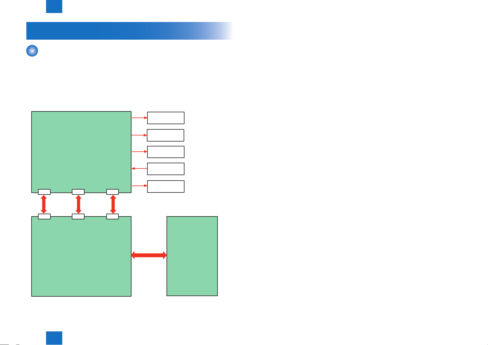
■Outline of Electric Circuits
Electric circuits of this machine are controlled by the main controller PCB2. The main
controller PCB2 detect the input signals from sensors to output the signals that
drive DC loads such as motors, solenoids, clutches, and fans at the predetermined timings.
The ADF driver PCB does not have a memory area; data such as the data used in the service
mode is stored in main controller PCB2.
Clutch
Fan
2-13
ADF driver PCB
J9 J11
J509 J503J504
J10
Reader relay PCB
Motor
Sensor
Solenoid
Main controller
PCB2
F-2-25
Technology > Basic Conguration (DADF) > Component Conguration > Outline of Electric Circuits
2
2-13
2
Technology > Basic Conguration (DADF) > Drive Conguration
2-14
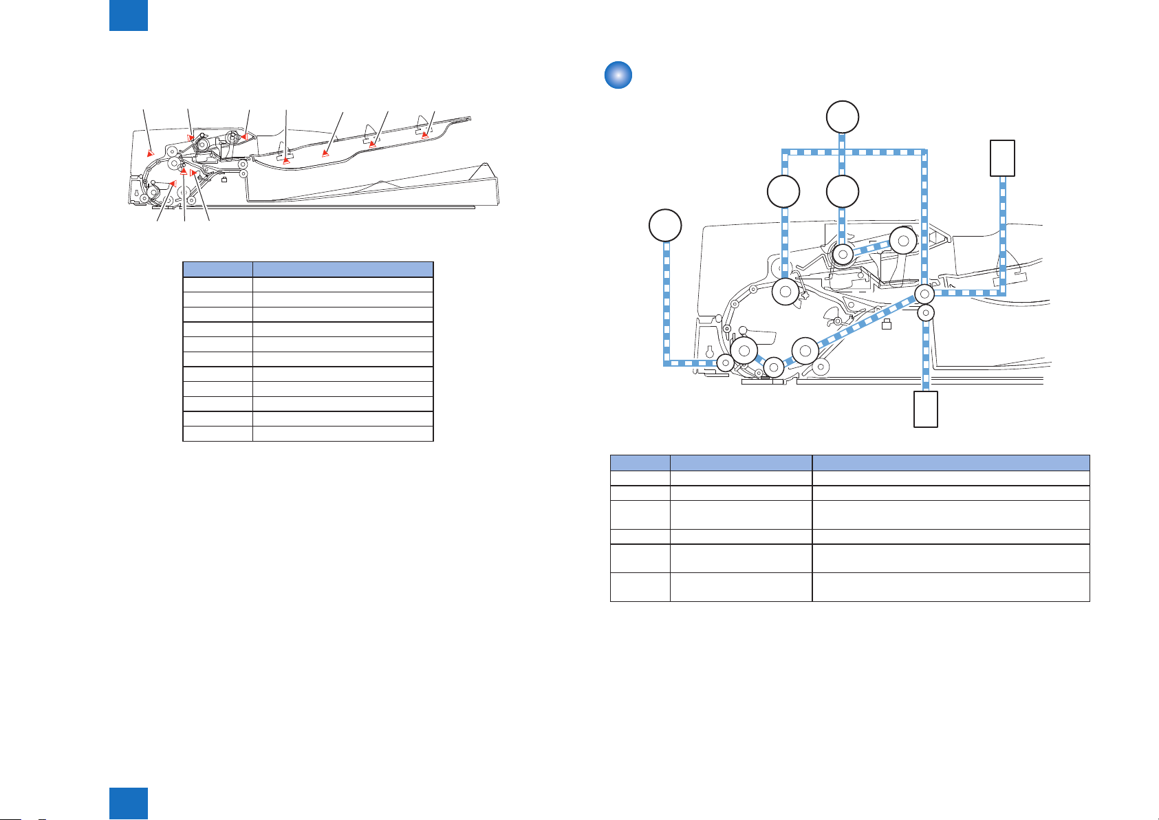
■Sensor Layout
SR11
SR4
SR2 SR1
SR5 SR7 PS1/PS2 SR8 SR9
SR3
No. Sensor name
SR1 Registration sensor
SR2 Read sensor
SR3 Delivery reversal sensor
SR4 Timing sensor
SR5 Document set sensor
SR7 Last document detection sensor
SR8 Document length sensor 2
SR9 Document length sensor 1
SR11 Release motor HP sensor
PS1 Document width sensor2
PS2 Document width sensor1
T-2-4
Drive Conguration
M1
SL1
CL2 CL1
M2
F-2-26
SL2
F-2-27
No. Part name Content
M1 ADF motor Feeds documents..
M2 Release motor Prevents a document from swaying.
SL1 Pressurization solenoid Shifts the delivery lower roller after reversal of the dual-
sided document, etc.
SL2 Stamp solenoid Drives the stamp mechanism.
CL1 Pickup clutch Drives the pickup clutch to transmit the power of the
pickup/feed motor to the pickup roller unit.
CL2 Registration clutch Drives the registration clutch to transmit the power of
the pickup/feed motor to the registration roller.
T-2-5
Technology > Basic Conguration (DADF) > Drive Conguration
2
2-14
2
Technology > Basic Conguration (DADF) > Outline of Operation Modes > Forward Pickup/Delivery Operation
2-15
Outline of Operation Modes
■Outline
This machine has four operation modes. This machine operates in the operation mode
specied by the host machine to perform printing. Operation mode names,
brief outline of operations, ad associated print modes are given in the following table:
Operation mode name Outline of operation Associated print mode
Forward pickup/delivery Picks up, reads, and then delivers
a document.
Forward feed/reverse delivery Picks up, reads, reverses, and
delivers a document.
Single-sided document ->
Simplex printing
Single-sided document ->
Duplex printing
Double-sided document ->
Duplex printing
Double-sided document ->
Simplex printing
T-2-6
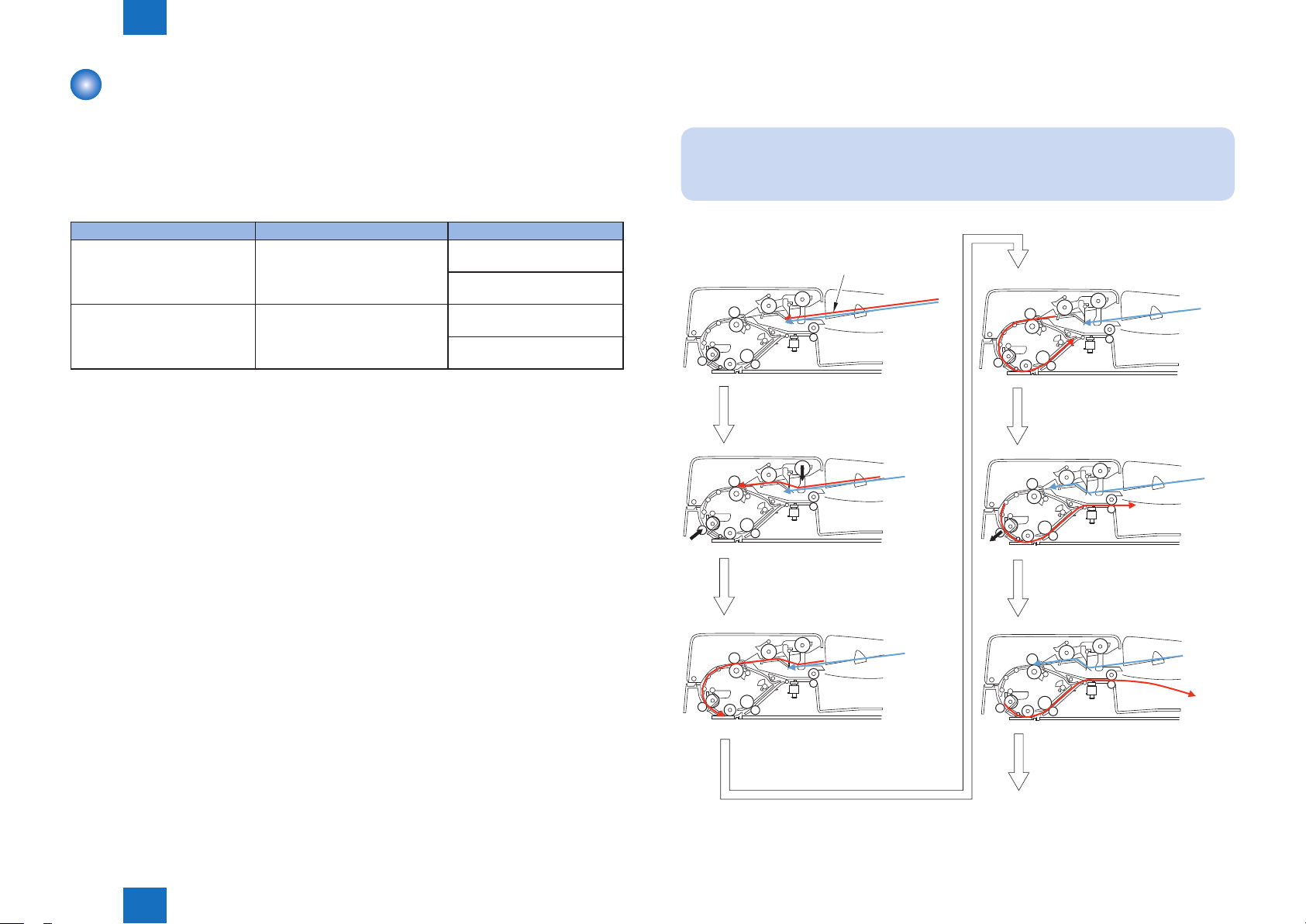
■Forward Pickup/Delivery Operation
• Simplex read operation (when two document sheets are placed)
NOTE:
This operation is performed for all single-sided documents irrespective of whether
document widths are the same or different.
Document
Reading of first document
sheet
Technology > Basic Conguration (DADF) > Outline of Operation Modes > Forward Pickup/Delivery Operation
2
Pickup of first document sheet/
Formation of loop
Waiting for reading of the
first document sheet
Pickup of second document
sheet
Formation of second document
To next
F-2-28
2-15
 Loading...